WO2022004847A1 - 産業機械の状態監視装置及び状態監視方法 - Google Patents
産業機械の状態監視装置及び状態監視方法 Download PDFInfo
- Publication number
- WO2022004847A1 WO2022004847A1 PCT/JP2021/024968 JP2021024968W WO2022004847A1 WO 2022004847 A1 WO2022004847 A1 WO 2022004847A1 JP 2021024968 W JP2021024968 W JP 2021024968W WO 2022004847 A1 WO2022004847 A1 WO 2022004847A1
- Authority
- WO
- WIPO (PCT)
- Prior art keywords
- moving image
- output signal
- robot
- input
- industrial machine
- Prior art date
- Legal status (The legal status is an assumption and is not a legal conclusion. Google has not performed a legal analysis and makes no representation as to the accuracy of the status listed.)
- Ceased
Links
Images



Classifications
-
- B—PERFORMING OPERATIONS; TRANSPORTING
- B25—HAND TOOLS; PORTABLE POWER-DRIVEN TOOLS; MANIPULATORS
- B25J—MANIPULATORS; CHAMBERS PROVIDED WITH MANIPULATION DEVICES
- B25J9/00—Program-controlled manipulators
- B25J9/16—Program controls
- B25J9/1694—Program controls characterised by use of sensors other than normal servo-feedback from position, speed or acceleration sensors, perception control, multi-sensor controlled systems, sensor fusion
- B25J9/1697—Vision controlled systems
-
- G—PHYSICS
- G05—CONTROLLING; REGULATING
- G05B—CONTROL OR REGULATING SYSTEMS IN GENERAL; FUNCTIONAL ELEMENTS OF SUCH SYSTEMS; MONITORING OR TESTING ARRANGEMENTS FOR SUCH SYSTEMS OR ELEMENTS
- G05B19/00—Program-control systems
- G05B19/02—Program-control systems electric
- G05B19/04—Program control other than numerical control, i.e. in sequence controllers or logic controllers
- G05B19/042—Program control other than numerical control, i.e. in sequence controllers or logic controllers using digital processors
- G05B19/0423—Input/output
-
- B—PERFORMING OPERATIONS; TRANSPORTING
- B25—HAND TOOLS; PORTABLE POWER-DRIVEN TOOLS; MANIPULATORS
- B25J—MANIPULATORS; CHAMBERS PROVIDED WITH MANIPULATION DEVICES
- B25J9/00—Program-controlled manipulators
- B25J9/16—Program controls
- B25J9/1656—Program controls characterised by programming, planning systems for manipulators
-
- B—PERFORMING OPERATIONS; TRANSPORTING
- B25—HAND TOOLS; PORTABLE POWER-DRIVEN TOOLS; MANIPULATORS
- B25J—MANIPULATORS; CHAMBERS PROVIDED WITH MANIPULATION DEVICES
- B25J9/00—Program-controlled manipulators
- B25J9/16—Program controls
- B25J9/1674—Program controls characterised by safety, monitoring, diagnostic
-
- G—PHYSICS
- G05—CONTROLLING; REGULATING
- G05B—CONTROL OR REGULATING SYSTEMS IN GENERAL; FUNCTIONAL ELEMENTS OF SUCH SYSTEMS; MONITORING OR TESTING ARRANGEMENTS FOR SUCH SYSTEMS OR ELEMENTS
- G05B2219/00—Program-control systems
- G05B2219/20—Pc systems
- G05B2219/24—Pc safety
- G05B2219/24097—Camera monitors controlled machine
-
- G—PHYSICS
- G05—CONTROLLING; REGULATING
- G05B—CONTROL OR REGULATING SYSTEMS IN GENERAL; FUNCTIONAL ELEMENTS OF SUCH SYSTEMS; MONITORING OR TESTING ARRANGEMENTS FOR SUCH SYSTEMS OR ELEMENTS
- G05B2219/00—Program-control systems
- G05B2219/30—Nc systems
- G05B2219/31—From computer integrated manufacturing till monitoring
- G05B2219/31447—Process error event detection and continuous process image detection, storage
-
- G—PHYSICS
- G05—CONTROLLING; REGULATING
- G05B—CONTROL OR REGULATING SYSTEMS IN GENERAL; FUNCTIONAL ELEMENTS OF SUCH SYSTEMS; MONITORING OR TESTING ARRANGEMENTS FOR SUCH SYSTEMS OR ELEMENTS
- G05B2219/00—Program-control systems
- G05B2219/30—Nc systems
- G05B2219/37—Measurements
- G05B2219/37572—Camera, tv, vision
Definitions
- This disclosure relates to a condition monitoring device and a condition monitoring method for industrial machinery.
- a robot operating under the control of a robot control device is imaged by an image pickup device, and the image information obtained by the image pickup device is associated with time information and robot work content information.
- the saved image information is displayed on the display device together with the time information and work content information. According to this robot monitoring system, it is possible for an operator to quickly and easily identify a location where an inconvenience has occurred.
- the technology for monitoring the state of the robot by recording the movement of the robot with an image pickup device is known.
- the conventional robot state monitoring device it is not possible to clarify the correlation between the robot operating state and the state of the output signal or input signal of the robot control device.
- This disclosure has been made in view of the above problems, and is an industrial machine condition monitoring device and condition monitoring that can easily clarify the correlation between the operating state of the industrial machine and the signal state of the controller along the time axis. Provide a method.
- One aspect of the present disclosure is an image pickup device that captures an industrial machine under the control of a controller, and an input / output signal that is at least one of an image data acquired by the image pickup device and an input signal and an output signal of the controller. It is provided with a moving image generation unit that generates a moving image representing a state change of the industrial machine and the input / output signal by associating along the time axis, and a moving image reproducing device that reproduces the moving image generated by the moving image generation unit. , It is a condition monitoring device for industrial machinery.
- One aspect of the present disclosure is to photograph an industrial machine under the control of a controller with an image pickup device, and to obtain video data acquired by the image pickup device and an input / output signal which is at least one of an input signal and an output signal of the controller. It is a state monitoring method of an industrial machine that generates a moving image showing a state change of the industrial machine and the input / output signal by associating them along a time axis, and reproduces the moving image by a moving image reproducing device.
- the correlation between the operating state of the industrial machine and the state of the input / output signal of the controller can be easily clarified along the time axis.
- FIG. 1 is a schematic diagram of a robot system 1 including a robot condition monitoring device 2 according to the present embodiment.
- the robot system 1 includes a robot 3 as an industrial machine, a first peripheral device 41, a second peripheral device 42, and a robot status monitoring device 2 for monitoring the status of the robot 3 and the peripheral devices 41 and 42.
- the robot 3 executes a series of transport operations of gripping the work at a predetermined position and transporting the gripped work to a predetermined position in response to a control signal transmitted from the controller 51 described later.
- the transfer robot is used will be described, the present disclosure is not limited to this.
- the robot 3 may be any robot such as a welding robot or a painting robot as long as it operates in response to a control signal transmitted from the controller 51.
- the robot condition monitoring device 2 includes a robot control device 5 that controls the robot 3, a camera 6 as an image pickup device that captures the transport operation of the robot 3, and a moving image reproducing device 7 that reproduces a moving image.
- the camera 6 is provided in the vicinity of the robot 3.
- the camera 6 captures the transfer operation of the robot 3 under the control of the robot control device 5 at a predetermined frame rate, and transmits the acquired video data of the robot 3 to the robot control device 5.
- the robot control device 5 includes a communication means (not shown) that communicates with peripheral devices 41 and 42 via a communication line 43, arithmetic processing means (not shown) such as a CPU (Central Processing Unit), and an HDD (not shown) that stores various programs.
- arithmetic processing means such as a CPU (Central Processing Unit)
- an HDD not shown
- Auxiliary storage means such as Hard Disk Drive) and SSD (Solid State Drive), and RAM (Random Access Memory) for storing data temporarily required for arithmetic processing means to execute programs.
- the robot control device 5 realizes various functions such as a controller 51, a program storage unit 52, a moving image generation unit 53, a program editing unit 54, and a moving image storage unit 55 by the hardware configuration.
- the controller 51 exchanges digital signals and analog signals with peripheral devices 41 and 42 via the communication line 43, and controls the robot 3 according to a program stored in the program storage unit 52.
- the program storage unit 52 stores a plurality of programs for defining the value of the output signal output from the controller 51 to the robot 3 and the peripheral devices 41 and 42 in the controller 51. At least a part of the plurality of programs stored in the program storage unit 52 can be edited by the program editing unit 54 described later.
- the moving image generation unit 53 acquires the video data of the robot 3 transmitted from the camera 6 and the input / output signals of the controller 51, and associates the acquired video data with the input / output signals along a common time axis. As a result, a moving image showing the state change of the robot 3 and the input / output signal (see FIG. 3 described later) is generated and stored in the moving image storage unit 55.
- the input / output signals of the controller 51 acquired by the moving image generation unit 53 include digital input signals (DI [1], DI [2], ...) Input to the controller 51 from the robot 3 and peripheral devices 41 and 42.
- Analog input signals (AI [1], AI [2], 7), digital output signals output from the controller 51 to the robot 3 and peripheral devices 41, 42 (DO [1], DO [2], ...) and At least one of the analog output signals (AO [1], AO [2], ).
- the digital signal means a signal that can take only two values consisting of ON and OFF
- the analog signal means a signal that can take an integer value within a predetermined range.
- the moving image playback device 7 is, for example, a mobile communication terminal such as a tablet terminal capable of communicating with the robot control device 5.
- the moving image reproduction device 7 reproduces the moving image generated by the moving image generation unit 53 and stored in the moving image storage unit 55 according to the operation of the operator.
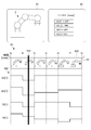
- 2A and 2B are diagrams schematically showing the relationship between the frame rate [fps] of the video data captured by the camera 6 and the update cycle [seconds] of the input / output signals.
- 2A and 2B show only the digital input / output signal DI [1] as the input / output signal acquired by the moving image generation unit 53.
- the frame rate of the video data is set to 60 [fps]
- the update cycle of the digital input signal DI [1] is set to 1/20 [seconds]
- the update cycle of the digital input signal DI [1] is 1.
- the present disclosure is not limited to this.
- the video data captured by the camera 6 has a plurality of frames F1, F2, F3, F4 ... Consists of. More specifically, the frame F1 is photographed at the time t1, the frame F2 is photographed at the time t2 1/60 [seconds] after the time t1, and the frame F3 is the time 2/60 [seconds] after the time t1. The image is taken at t3, and the frame F4 is taken at time t4, which is 3/60 [seconds] after time t1.
- the moving image generation unit 53 acquires and acquires the value of the digital input signal DI [1] at the recording times t1 to t4 of each frame F1 to F4 under the same cycle as the frame rate of the video data of the camera 6.
- a moving image as shown in FIG. 3 described later showing a state change of the robot 3 and the digital input signal DI [1].
- the digital input signal DI [1] is updated every 1/20 [seconds]. Therefore, the value of the digital input signal DI [1], which was “OFF” at time t1, is switched to “ON” at time t4. Therefore, in this case, the moving image generation unit 53 acquires "OFF” as the value of the digital input signal DI [1] at the recording time t1 of the frame F1, and the value of the digital input signal DI [1] at the recording time t2 of the frame F2. "OFF” is acquired as the value of the digital input signal DI [1] at the recording time t3 of the frame F3, and "OFF” is acquired as the value of the digital input signal DI [1] at the recording time t4 of the frame F4. Get "ON".
- the digital input signal DI [1] is updated every 1/40 [seconds]. Therefore, the value of the digital input signal DI [1], which was “OFF” at time t1, is switched to "ON” at time t5 between time t2 and then to "OFF” at time t4. .. Therefore, in this case, the moving image generation unit 53 acquires "OFF” as the value of the digital input signal DI [1] at the recording time t1 of the frame F1, and the value of the digital input signal DI [1] at the recording time t2 of the frame F2. "OFF” is acquired as the value of the digital input signal DI [1] at the recording time t3 of the frame F3, and “ON” is acquired as the value of the digital input signal DI [1] at the recording time t4 of the frame F4. Get "OFF".
- the moving image generation unit 53 acquires the input / output signal values of the controller 51 at the recording time of each frame under the same cycle as the frame rate of the video data of the camera 6. Therefore, the reciprocal of the frame rate of the camera 6 (shooting cycle of each frame) is set to be equal to or less than the update cycle of the input / output signal of the controller 51 so that the moving image generation unit 53 can acquire all the state changes of the input / output signal of the controller 51. It is preferable to do so.
- FIG. 3 is a diagram showing an example of a moving image generated by the moving image generation unit 53.
- the moving image generation unit 53 associates the video data of the robot 3 acquired as described above with the input / output signals of the controller 51 along a common time axis, so that the moving image display field 81 (as illustrated in FIG. 3) ( A moving image including a signal status display column 82 (see the upper right side in FIG. 3) and a timeline column 83 (see the lower row in FIG. 3) is generated in FIG.
- the value of the time t (hereinafter referred to as “current time t”) specified by the time bar 833 described later and the input / output signal selected by the operator (in the example of FIG. 3, digital).
- the value at the current time t of the output signal DO [1], the analog output signal AO [1], the digital input signal DI [1], and the analog input signal AI [1] is shown). Is displayed.
- a moving image of the robot 3 (that is, an image obtained by continuously reproducing a still image taken by the camera 6 at a predetermined frame rate) is displayed.
- FIG. 3 shows a case where a still image of the robot 3 at the above-mentioned current time t is displayed.
- a time axis 830 extending in the left-right direction in FIG. 3, a band-shaped frame bar 831 extending in parallel with the time axis 830 below the time axis 830, and a time below the frame bar 831.
- a time chart column 832 of an input / output signal extending parallel to the axis 830 and a time bar 833 extending along the time axis 830, the frame bar 831, and the time chart column 832 in the vertical direction in FIG. 3 are displayed. ..
- the above-mentioned current time t corresponds to a coordinate value on the time axis 830 of the time bar 833.
- a plurality of still images of the robot 3 in each frame are arranged on the frame bar 831 along the time axis 830. That is, the moving image of the robot 3 displayed in the moving image display field 81 described above is an image obtained by continuously reproducing a plurality of still images arranged along the time axis 830 in the frame bar 831.
- the time chart column 832 shows changes in the values of the plurality of input / output signals DO [1], AO [1], DI [1], and AI [1] selected by the operator along the time axis 830.
- the time chart image is displayed.
- the operator can scroll the time axis 830, the frame bar 831, and the time chart column 832 integrally in the left-right direction while fixing the position of the time bar 833, or the time axis. While fixing the positions of the 830, the frame bar 831, and the time chart column 832, only the time bar 833 can be scrolled in the left-right direction.
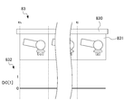
- the program editing unit 54 stops the playing moving image and illustrates it in FIG. 4A.
- the program editing image is displayed on the moving image playback device 7, and the program shifts to the program editing mode for editing the program of the digital output signal DO [1].
- the program editing unit 54 displays the program editing image including at least the timeline column 83 on the moving image playback device 7.
- the timeline column 83 in the program edited image is a time chart of a frame bar 831 in which a still image of the robot 3 in each frame is displayed and a digital output signal DO [1] generated by a program editable by the program editor 54.
- the program editing unit 54 edits a program that defines the value of the digital output signal DO [1] based on a predetermined editing operation on the moving image playback device 7 by the operator in the program edited image as shown in FIG. 4A.
- the operator can directly change the value of the digital output signal DO [1] in the program edited image.
- the program editing unit 54 associates the value of the digital output signal DO [1] changed by the editing operation with the state of the robot 3 displayed on the frame bar 831. And edit the program of the digital output signal DO [1].
- FIG. 4A and 4B show the case where the hand of the robot 3 is open from time th to ti and closed after time ti.
- the solid line indicates the value of the digital output signal DO [1] generated according to the program before being edited by the program editing unit 54
- the broken line indicates the digital output signal after being changed by the editing operation by the operator.
- the value of DO [1] is shown.
- FIG. 4B shows a case where the editing operation for changing the value of the digital output signal DO [1] after the time ti is performed from “0” to “1”.
- the program editing unit 54 associates the changed value of the digital output signal DO [1] with the state of the robot 3 so that the digital output signal DO [ Edit the program in 1]. More specifically, the program editorial unit 54 outputs a digital output signal so as to output "0" while the hand of the robot 3 is open and “1" while the hand of the robot 3 is closed. Edit the program of DO [1]. Therefore, according to the program edited by the program editing unit 54, the controller 51 sets the value of the digital output signal DO [1] to "0" while the hand of the robot 3 is open, and the hand of the robot 3 is closed. During the period, the value of the digital output signal DO [1] is set to "1".
- the robot status monitoring device 2 monitors the status of the robot 3 and peripheral devices 41 and 42 according to the following procedure.
- FIG. 3 shows a state change of the robot 3 and the input / output signal by associating the video data acquired by the camera 6 with the input / output signal of the controller 51 along the time axis using the moving image generation unit 53.
- Such a moving image is generated and saved in the moving image storage unit 55.
- the moving image reproduction device 7 the moving image stored in the moving image storage unit 55 is reproduced.
- the robot state monitoring device 2 has a camera 6 that captures the robot 3 under the control of the controller 51, and a common time axis 830 for the video data acquired by the camera 6 and the input / output signals of the controller 51.
- a video generation unit 53 that generates a video representing a state change of the robot 3 and an input / output signal, and a video that reproduces a video generated by the video generation unit 53 and stored in the video storage unit 55.
- a reproduction device 7 is provided. According to the present embodiment, by generating such a moving image, the operator only sees the moving image reproduced by the moving image reproducing device 7, and the operating state of the robot 3 and the input / output signal state of the controller 51. At the same time, the correlation between the operating state of the robot 3 and the state of the input / output signal of the controller 51 can be easily clarified along the time axis 830.
- the moving image generation unit 53 uses the input / output signal values of the controller 51 at the recording time of each frame under the same cycle as the frame rate of the video data captured by the camera 6. To get. According to the present embodiment, by setting the shooting cycle of each frame to be equal to or less than the update cycle of the input / output signals, it is possible to acquire all the state changes of the input / output signals of the controller 51.
- the moving image generation unit 53 has a moving image display field 81 in which a moving image of the robot 3 is displayed, and a robot 3 in each frame arranged in plurality along the time axis 830. Generates a moving image including a frame bar 831 including a still image of the above, a timeline column 83 in which a time chart image of an input / output signal along a time axis 830 is displayed, and a timeline column 83.
- the operator can simply watch the moving image reproduced by the moving image reproducing device 7 and the robot 3 can use the moving image.
- the operating state and the input / output signal state of the controller 51 can be confirmed at the same time, and the correlation between the operating state of the robot 3 and the input / output signal state of the controller 51 can be easily clarified along the time axis 830.
- the program editing unit 54 edits the program stored in the program storage unit 52 based on the editing operation by the operator in the program editing image including the timeline column 83. do. This is convenient because the operator can easily visually edit the program according to the state of the robot 3 displayed in the timeline column 83.
- the state monitoring device for the industrial machine of the present disclosure is applied to the robot state monitoring device 2, but the present invention is not limited to this.
- the robot 3 it can be applied to a condition monitoring device for industrial machines such as various machine tools.
- the moving image playback device 7 is a mobile communication terminal such as a tablet terminal having a communication function and a moving image display function has been described, but the present invention is not limited to this.
- the moving image reproduction device 7 may be a portable teaching device provided with an operation key that can be operated by an operator to teach a predetermined operation to the robot 3 and a display capable of displaying a moving image.
- Robot system 2 ... Robot condition monitoring device (condition monitoring device for industrial machinery) 3 ... Robot (industrial machine) 41 ... 1st peripheral device 42 ... 2nd peripheral device 43 ... Communication line 5 ... Robot control device 51 ... Controller 53 ... Video generation unit 54 ... Program editing unit 55 ... Video storage unit 6 ... Camera (imaging device) 7 ... Video playback device (video playback device, teaching device for industrial machines) 81 ... Dynamic image display column 82 ... Signal status display column 83 ... Timeline column
Landscapes
- Engineering & Computer Science (AREA)
- Robotics (AREA)
- Mechanical Engineering (AREA)
- Physics & Mathematics (AREA)
- General Physics & Mathematics (AREA)
- Automation & Control Theory (AREA)
- Numerical Control (AREA)
- Manipulator (AREA)
- Testing And Monitoring For Control Systems (AREA)
Abstract
Description
本実施形態に係るロボット状態監視装置2は、コントローラ51による制御下におけるロボット3を撮影するカメラ6と、このカメラ6によって取得された映像データとコントローラ51の入出力信号とを共通の時間軸830に沿って関連付けることにより、ロボット3及び入出力信号の状態変化を表す動画を生成する動画生成部53と、この動画生成部53によって生成され、動画保存部55に保存された動画を再生する動画再生装置7と、を備える。本実施形態によれば、これのような動画を生成することにより、作業者は動画再生装置7によって再生される動画を視るだけで、ロボット3の動作状態とコントローラ51の入出力信号の状態とを同時に確認でき、ひいてはロボット3の動作状態とコントローラ51の入出力信号の状態との相関を時間軸830に沿って容易に明らかにできる。
2…ロボット状態監視装置(産業機械の状態監視装置)
3…ロボット(産業機械)
41…第1周辺機器
42…第2周辺機器
43…通信線
5…ロボット制御装置
51…コントローラ
53…動画生成部
54…プログラム編集部
55…動画保存部
6…カメラ(撮像装置)
7…動画再生装置(動画再生装置、産業機械の教示装置)
81…動画像表示欄
82…信号状態表示欄
83…タイムライン欄
Claims (6)
- コントローラによる制御下における産業機械を撮影する撮像装置と、
前記撮像装置によって取得された映像データと前記コントローラの入力信号及び出力信号の少なくとも何れかである入出力信号とを時間軸に沿って関連付けることにより、前記産業機械及び前記入出力信号の状態変化を表す動画を生成する動画生成部と、
前記動画生成部によって生成された動画を再生する動画再生装置と、を備える、産業機械の状態監視装置。 - 前記動画生成部は、前記映像データのフレームレートと同じ周期の下、各フレームの記録時刻における前記入出力信号の値を取得する、請求項1に記載の産業機械の状態監視装置。
- 前記動画生成部は、
前記産業機械の動画像が表示される動画像表示欄と、
前記時間軸に沿って複数配置された各フレームにおける前記産業機械の静止画像及び前記時間軸に沿った前記入出力信号のタイムチャート画像が表示されるタイムライン欄と、を含む動画を生成する、請求項1又は2に記載の産業機械の状態監視装置。 - 前記コントローラにおいて出力信号の値を規定するためのプログラムを記憶するプログラム記憶部と、
前記タイムライン欄を含む編集画像における作業者による操作に基づいて前記プログラムを編集するプログラム編集部と、を備えることを特徴とする請求項3に記載の産業機械の状態監視装置。 - 前記動画再生装置は、前記産業機械の教示装置である、請求項1から4の何れかに記載の産業機械の状態監視装置。
- コントローラによる制御下における産業機械を撮像装置によって撮影し、
前記撮像装置によって取得された映像データと前記コントローラの入力信号及び出力信号の少なくとも何れかである入出力信号とを時間軸に沿って関連付けることにより、前記産業機械及び前記入出力信号の状態変化を表す動画を生成し、
前記動画を動画再生装置によって再生する、産業機械の状態監視方法。
Priority Applications (4)
| Application Number | Priority Date | Filing Date | Title |
|---|---|---|---|
| JP2022534113A JP7525606B2 (ja) | 2020-07-03 | 2021-07-01 | 産業機械の状態監視装置及び状態監視方法 |
| DE112021003600.9T DE112021003600B4 (de) | 2020-07-03 | 2021-07-01 | Zustandsüberwachungsvorrichtung und Zustandsüberwachungsverfahren für Industriemaschinen |
| CN202180046536.5A CN115734850B (zh) | 2020-07-03 | 2021-07-01 | 工业机械的状态监视装置以及状态监视方法 |
| US18/003,261 US12384043B2 (en) | 2020-07-03 | 2021-07-01 | State monitoring device and state monitoring method for industrial machinery |
Applications Claiming Priority (2)
| Application Number | Priority Date | Filing Date | Title |
|---|---|---|---|
| JP2020-115433 | 2020-07-03 | ||
| JP2020115433 | 2020-07-03 |
Publications (1)
| Publication Number | Publication Date |
|---|---|
| WO2022004847A1 true WO2022004847A1 (ja) | 2022-01-06 |
Family
ID=79315334
Family Applications (1)
| Application Number | Title | Priority Date | Filing Date |
|---|---|---|---|
| PCT/JP2021/024968 Ceased WO2022004847A1 (ja) | 2020-07-03 | 2021-07-01 | 産業機械の状態監視装置及び状態監視方法 |
Country Status (5)
| Country | Link |
|---|---|
| US (1) | US12384043B2 (ja) |
| JP (1) | JP7525606B2 (ja) |
| CN (1) | CN115734850B (ja) |
| DE (1) | DE112021003600B4 (ja) |
| WO (1) | WO2022004847A1 (ja) |
Cited By (1)
| Publication number | Priority date | Publication date | Assignee | Title |
|---|---|---|---|---|
| WO2024134339A1 (en) * | 2022-12-23 | 2024-06-27 | G.D S.P.A | System for monitoring a manufacturing machine |
Citations (3)
| Publication number | Priority date | Publication date | Assignee | Title |
|---|---|---|---|---|
| JPH01250109A (ja) * | 1988-03-30 | 1989-10-05 | Kobe Steel Ltd | ロボットのシミュレーション装置 |
| JP2006228029A (ja) * | 2005-02-18 | 2006-08-31 | Denso Corp | 監視制御装置及び監視制御方法 |
| JP2019164470A (ja) * | 2018-03-19 | 2019-09-26 | キヤノン株式会社 | プログラムプロダクト及び監視制御システム並びに情報処理装置 |
Family Cites Families (8)
| Publication number | Priority date | Publication date | Assignee | Title |
|---|---|---|---|---|
| JP2004174662A (ja) * | 2002-11-27 | 2004-06-24 | Fanuc Ltd | ロボットの動作状態解析装置 |
| JP2007061983A (ja) * | 2005-09-01 | 2007-03-15 | Fanuc Ltd | ロボット監視システム |
| US9046757B2 (en) * | 2010-10-29 | 2015-06-02 | Keyence Corporation | Moving image pickup apparatus, method for observing moving image, moving image observing program, and computer-readable recording medium |
| JP5849403B2 (ja) * | 2011-02-15 | 2016-01-27 | セイコーエプソン株式会社 | ロボットコントローラー、ロボット、及び、ロボットシステム |
| JP5939267B2 (ja) | 2014-03-05 | 2016-06-22 | 株式会社安川電機 | ロボット監視システム、ロボット監視装置、ロボット監視方法、ロボット監視モジュール、およびロボット監視プログラム |
| DE112015000292B4 (de) * | 2015-07-31 | 2021-02-11 | Komatsu Ltd. | Arbeitsmaschinen-Anzeigesystem, Arbeitsmaschinen-Anzeigevorrichtung und Arbeitsmaschinen-Anzeigeverfahren |
| JP6088679B1 (ja) * | 2016-02-19 | 2017-03-01 | ファナック株式会社 | カメラの画像により故障を判定するロボットシステムの故障診断装置 |
| JP6965844B2 (ja) | 2018-08-08 | 2021-11-10 | オムロン株式会社 | 制御システム、解析装置および制御方法 |
-
2021
- 2021-07-01 JP JP2022534113A patent/JP7525606B2/ja active Active
- 2021-07-01 CN CN202180046536.5A patent/CN115734850B/zh active Active
- 2021-07-01 US US18/003,261 patent/US12384043B2/en active Active
- 2021-07-01 DE DE112021003600.9T patent/DE112021003600B4/de active Active
- 2021-07-01 WO PCT/JP2021/024968 patent/WO2022004847A1/ja not_active Ceased
Patent Citations (3)
| Publication number | Priority date | Publication date | Assignee | Title |
|---|---|---|---|---|
| JPH01250109A (ja) * | 1988-03-30 | 1989-10-05 | Kobe Steel Ltd | ロボットのシミュレーション装置 |
| JP2006228029A (ja) * | 2005-02-18 | 2006-08-31 | Denso Corp | 監視制御装置及び監視制御方法 |
| JP2019164470A (ja) * | 2018-03-19 | 2019-09-26 | キヤノン株式会社 | プログラムプロダクト及び監視制御システム並びに情報処理装置 |
Cited By (1)
| Publication number | Priority date | Publication date | Assignee | Title |
|---|---|---|---|---|
| WO2024134339A1 (en) * | 2022-12-23 | 2024-06-27 | G.D S.P.A | System for monitoring a manufacturing machine |
Also Published As
| Publication number | Publication date |
|---|---|
| JPWO2022004847A1 (ja) | 2022-01-06 |
| CN115734850A (zh) | 2023-03-03 |
| DE112021003600T5 (de) | 2023-04-20 |
| CN115734850B (zh) | 2025-10-28 |
| JP7525606B2 (ja) | 2024-07-30 |
| US12384043B2 (en) | 2025-08-12 |
| US20230241779A1 (en) | 2023-08-03 |
| DE112021003600B4 (de) | 2026-04-23 |
Similar Documents
| Publication | Publication Date | Title |
|---|---|---|
| JP2003298982A5 (ja) | ||
| WO2022004847A1 (ja) | 産業機械の状態監視装置及び状態監視方法 | |
| EP0476985B1 (en) | Video special effects generation | |
| US4736256A (en) | Method for recording and for confirming the recording of images in an image filing apparatus | |
| JP2006352529A (ja) | 撮像装置 | |
| JP7103967B2 (ja) | 情報処理装置及びプログラム | |
| JP2006060279A (ja) | 動画再生装置 | |
| JP5164367B2 (ja) | 画像表示処理装置、処理方法及びプログラム | |
| JP2016119648A (ja) | パラメータ記録制御装置及びその制御方法 | |
| CN102469257B (zh) | 再现装置及再现方法 | |
| JP2018074337A (ja) | 動画処理装置、動画処理方法およびプログラム | |
| JP3797762B2 (ja) | 動画像編集方法 | |
| US20040091043A1 (en) | Video signal processor and video camera | |
| JP4168048B2 (ja) | 動画像編集方法 | |
| US20250260848A1 (en) | Electronic device and shooting management method | |
| JP4699144B2 (ja) | 映像切替制御装置及び映像切替制御方法 | |
| JP4189231B2 (ja) | 監視用記録再生装置 | |
| JP2002006726A (ja) | 作業指導システム、作業指導方法及び記憶媒体 | |
| JP2008011044A (ja) | ビデオカメラ | |
| JP2006229592A (ja) | コンテンツ作成装置、画像/音声出力装置および制御プログラム | |
| WO2024190280A1 (ja) | データ生成装置およびデータ生成方法 | |
| TW202437156A (zh) | 資料生成裝置以及資料生成方法 | |
| JPH08205077A (ja) | Vtr編集システム | |
| JPH09270995A (ja) | デジタル映像記録装置 | |
| JPH0745046A (ja) | 画像記録再生装置 |
Legal Events
| Date | Code | Title | Description |
|---|---|---|---|
| 121 | Ep: the epo has been informed by wipo that ep was designated in this application |
Ref document number: 21833527 Country of ref document: EP Kind code of ref document: A1 |
|
| ENP | Entry into the national phase |
Ref document number: 2022534113 Country of ref document: JP Kind code of ref document: A |
|
| 122 | Ep: pct application non-entry in european phase |
Ref document number: 21833527 Country of ref document: EP Kind code of ref document: A1 |
|
| WWG | Wipo information: grant in national office |
Ref document number: 18003261 Country of ref document: US |
|
| WWG | Wipo information: grant in national office |
Ref document number: 202180046536.5 Country of ref document: CN |