WO2022004712A1 - Retardateur, projecteur à cristaux liquides et procédé de réglage de contraste - Google Patents
Retardateur, projecteur à cristaux liquides et procédé de réglage de contraste Download PDFInfo
- Publication number
- WO2022004712A1 WO2022004712A1 PCT/JP2021/024535 JP2021024535W WO2022004712A1 WO 2022004712 A1 WO2022004712 A1 WO 2022004712A1 JP 2021024535 W JP2021024535 W JP 2021024535W WO 2022004712 A1 WO2022004712 A1 WO 2022004712A1
- Authority
- WO
- WIPO (PCT)
- Prior art keywords
- phase difference
- axis
- film
- retardation
- liquid crystal
- Prior art date
Links
Images


Classifications
-
- G—PHYSICS
- G02—OPTICS
- G02F—OPTICAL DEVICES OR ARRANGEMENTS FOR THE CONTROL OF LIGHT BY MODIFICATION OF THE OPTICAL PROPERTIES OF THE MEDIA OF THE ELEMENTS INVOLVED THEREIN; NON-LINEAR OPTICS; FREQUENCY-CHANGING OF LIGHT; OPTICAL LOGIC ELEMENTS; OPTICAL ANALOGUE/DIGITAL CONVERTERS
- G02F1/00—Devices or arrangements for the control of the intensity, colour, phase, polarisation or direction of light arriving from an independent light source, e.g. switching, gating or modulating; Non-linear optics
- G02F1/01—Devices or arrangements for the control of the intensity, colour, phase, polarisation or direction of light arriving from an independent light source, e.g. switching, gating or modulating; Non-linear optics for the control of the intensity, phase, polarisation or colour
- G02F1/13—Devices or arrangements for the control of the intensity, colour, phase, polarisation or direction of light arriving from an independent light source, e.g. switching, gating or modulating; Non-linear optics for the control of the intensity, phase, polarisation or colour based on liquid crystals, e.g. single liquid crystal display cells
- G02F1/133—Constructional arrangements; Operation of liquid crystal cells; Circuit arrangements
- G02F1/1333—Constructional arrangements; Manufacturing methods
- G02F1/1335—Structural association of cells with optical devices, e.g. polarisers or reflectors
- G02F1/13363—Birefringent elements, e.g. for optical compensation
- G02F1/133634—Birefringent elements, e.g. for optical compensation the refractive index Nz perpendicular to the element surface being different from in-plane refractive indices Nx and Ny, e.g. biaxial or with normal optical axis
-
- G—PHYSICS
- G02—OPTICS
- G02B—OPTICAL ELEMENTS, SYSTEMS OR APPARATUS
- G02B5/00—Optical elements other than lenses
- G02B5/30—Polarising elements
-
- G—PHYSICS
- G02—OPTICS
- G02F—OPTICAL DEVICES OR ARRANGEMENTS FOR THE CONTROL OF LIGHT BY MODIFICATION OF THE OPTICAL PROPERTIES OF THE MEDIA OF THE ELEMENTS INVOLVED THEREIN; NON-LINEAR OPTICS; FREQUENCY-CHANGING OF LIGHT; OPTICAL LOGIC ELEMENTS; OPTICAL ANALOGUE/DIGITAL CONVERTERS
- G02F1/00—Devices or arrangements for the control of the intensity, colour, phase, polarisation or direction of light arriving from an independent light source, e.g. switching, gating or modulating; Non-linear optics
- G02F1/01—Devices or arrangements for the control of the intensity, colour, phase, polarisation or direction of light arriving from an independent light source, e.g. switching, gating or modulating; Non-linear optics for the control of the intensity, phase, polarisation or colour
- G02F1/13—Devices or arrangements for the control of the intensity, colour, phase, polarisation or direction of light arriving from an independent light source, e.g. switching, gating or modulating; Non-linear optics for the control of the intensity, phase, polarisation or colour based on liquid crystals, e.g. single liquid crystal display cells
- G02F1/133—Constructional arrangements; Operation of liquid crystal cells; Circuit arrangements
- G02F1/1333—Constructional arrangements; Manufacturing methods
- G02F1/1335—Structural association of cells with optical devices, e.g. polarisers or reflectors
- G02F1/13363—Birefringent elements, e.g. for optical compensation
- G02F1/133632—Birefringent elements, e.g. for optical compensation with refractive index ellipsoid inclined relative to the LC-layer surface
-
- G—PHYSICS
- G03—PHOTOGRAPHY; CINEMATOGRAPHY; ANALOGOUS TECHNIQUES USING WAVES OTHER THAN OPTICAL WAVES; ELECTROGRAPHY; HOLOGRAPHY
- G03B—APPARATUS OR ARRANGEMENTS FOR TAKING PHOTOGRAPHS OR FOR PROJECTING OR VIEWING THEM; APPARATUS OR ARRANGEMENTS EMPLOYING ANALOGOUS TECHNIQUES USING WAVES OTHER THAN OPTICAL WAVES; ACCESSORIES THEREFOR
- G03B21/00—Projectors or projection-type viewers; Accessories therefor
Definitions
- the present disclosure relates to a retardation plate, a liquid crystal projector, and a contrast adjustment method.
- the phase difference plate is used as a phase difference compensation plate, for example, in a liquid crystal display device in a VA (Vertical Element) mode (see Japanese Patent No. 4744606).
- VA Vertical Element
- the polarizing element and the analyzer that sandwich the liquid crystal layer have a cross Nicol arrangement in which the respective transmission axes that transmit light are orthogonal to each other, and the orientation of the liquid crystal layer in a low voltage state is the substrate. Be perpendicular to the surface. Therefore, in the low voltage state, the linearly polarized light transmitted through the polarizing element is transmitted through the liquid crystal layer while maintaining the orientation of the polarization axis, and is incident on the analyzer.
- the liquid crystal layer has a refractive index anisotropy (also called birefringence) that causes a difference in refractive index between polarized light having different polarization axes due to the obliquely oriented component, it transmits through the liquid crystal layer.
- the light produced causes a phase difference between polarized light having different polarization axes.
- phase difference compensating plate compensates for the phase difference occurring in the liquid crystal layer. That is, the phase difference compensating plate reduces the light transmitted through the analyzer by generating a phase difference that cancels the phase difference caused by the liquid crystal layer. It has a function to improve the contrast of black display.
- the phase difference compensating plate is configured as, for example, a laminate of a plurality of plates having different optical anisotropy.
- Japanese Patent No. 4744606 describes a C plate and an O plate as a plurality of plates.
- the C plate is formed by laminating layers having different refractive indexes in the normal direction of the plate.
- the direction of the optical axis of the C plate which does not show refractive index anisotropy, coincides with the normal of the plate, and causes a phase difference with respect to light incident from a direction different from the normal.
- Japanese Patent Application Laid-Open No. 10-81955 as a problem of the oblique vapor deposition film used as a retardation plate, the oblique vapor deposition film is caused by the relaxation of the columnar structure formed by standing a plurality of columnar structures. It is disclosed that light is scattered inside, the oblique vapor deposition film becomes cloudy, and the quality of the retardation plate deteriorates. Relaxation of columnar structures refers to a phenomenon in which agglomeration occurs in a plurality of columnar structures that stand in a forest. Further, Japanese Patent Application Laid-Open No. 10-81955 discloses that a retardation plate in which light scattering in a film is suppressed can be obtained by alternately laminating an orthic vapor deposition film and a front vapor deposition film. There is.
- Japanese Unexamined Patent Publication No. 2013-113869 discloses that in a refractive index ellipsoid showing the characteristics of an O plate, the axis showing the maximum main refractive index substantially coincides with the growth direction which is the longitudinal direction of the columnar structure. ing. Further, in this O plate, the phase difference Re (30) from the direction inclined by 30 ° toward the growth direction side of the columnar structure with respect to the normal direction and 30 ° opposite to the growth direction with respect to the normal direction. It is disclosed that the ratio Re (30) / Re (-30) with the phase difference Re (-30) from the inclined direction is preferably 3.5 or more and 4.5 or less.
- Japanese Patent Application Laid-Open No. 2009-145861 also discloses an O-plate in which the axis showing the maximum principal refractive index substantially coincides with the longitudinal direction of the columnar structure, as in Japanese Patent Application Laid-Open No. 2013-113869. Further, in Japanese Patent Application Laid-Open No. 2009-145861, high contrast display is displayed on the liquid crystal display device by setting the phase difference ratio Re (-30) and the front phase difference Re (0) of the O plate to appropriate values. It is disclosed that it can be realized.
- One embodiment of the present disclosure is to provide a retardation plate, a liquid crystal projector, and a contrast adjusting method capable of compensating for the phase difference caused by the liquid crystal layer and increasing the contrast as compared with the conventional case. do.
- the retardation plate of the present disclosure comprises a substrate and a retardation film formed on at least one surface of the substrate, and the retardation film is inclined with respect to the normal of the film forming surface on which the retardation film is formed on the substrate.
- the three main refractive indexes in the biaxial refractive index ellipse exhibiting refractive index anisotropy are nx, ny, and nz, and the main refractive index in the X-axis direction, which is the longitudinal direction of the columnar structure, is nx.
- conditional expression (1) is satisfied when the main refractive index in the Y-axis direction, which is the major axis direction, is ny and the main refractive index in the Z-axis direction, which is the minor axis direction, is nz in the ellipse perpendicular to the X-axis. death,
- the incident angle in the direction inclined toward the X-axis side with respect to the normal is positive
- the phase difference of the incident light at the incident angle of + 30 ° is Re (+30)
- the phase difference of the incident light at the incident angle of -30 ° is set.
- the phase difference ratio which is the ratio of Re (+30) and Re (-30)
- Re (30) ratio is satisfied.
- the Y-axis corresponding to the maximum principal refractive index ny of the three principal refractive indexes is projected onto a plane parallel to the film forming surface, and corresponds to the principal refractive index ny.
- the slow axis is orthogonal to the ZS axis.
- Re (30) ratio satisfies the following conditional expression (2-1).
- the Re (30) ratio preferably satisfies the following conditional expression (2-3).
- the oblique film is Si (silicon), Nb (niobium), Zr (zirconium), Ti (titalum), La (lanthanum), Al (aluminum), Hf (hafnium) and Ta. It is preferably composed of an oxide containing at least one of (tantalum).
- two or more retardation films may be laminated.
- the Y-axis corresponding to the maximum principal refractive index ny of the three principal refractive indexes is projected onto a plane parallel to the film forming surface, and corresponds to the principal refractive index ny.
- the YS axis in which the phase of the incident light is most delayed is used as the slow axis, and the direction of the slow axis when the substrate is rotated about the normal is defined as the azimuth angle of the substrate.
- the azimuth that maximizes the phase difference that occurs with respect to the incident light with an incident angle of + 15 ° with respect to the normal is used as the reference azimuth
- the azimuth is used as the reference azimuth.
- the absolute value of the difference between the first phase difference of the incident light at + 45 ° and the second phase difference of the incident light when the azimuth is ⁇ 45 ° with respect to the reference azimuth is 6 nm or less. Is preferable.
- the frontal retardation is 0.1 mm to 5 nm.
- the haze value indicating the degree of generation of scattered light is 0.3% or less.
- the retardation films when two or more retardation films are laminated, it is preferable that the retardation films are formed one layer on each side of the substrate.
- the retardation film when two or more retardation films are laminated, the retardation film is laminated on one surface of the substrate, and further, an intermediate layer is formed between adjacent retardation films. May be provided.
- a plurality of substrates on which at least one retardation film is formed may be provided.
- the retardation films are laminated in two layers, and the slow axes of the retardation films are displaced from each other at an crossing angle within ⁇ 3 ° from 90 °.
- the retardation film is laminated in two layers and the difference in frontal retardation between them is ⁇ 3 nm or less.
- the retardation plate of the present disclosure may further include a negative C plate having a haze value of 0.4% or less, which indicates the degree of generation of scattered light.
- the C plate has an antireflection function.
- the haze value indicating the degree of generation of scattered light is 1% or less.
- the retardation plate of the present disclosure is a retardation plate including a substrate and a retardation film formed on at least one surface of the substrate, and two or more layers of retardation films are laminated.
- the axis where the phase of the incident light is most delayed is the slow phase axis, and the slow axis when the substrate is rotated around the normal.
- the orientation is the azimuth of the board Among the azimuths from 0 ° to 360 °, the azimuth that maximizes the phase difference that occurs with respect to the incident light with an incident angle of + 15 ° with respect to the normal is used as the reference azimuth, and the azimuth is used as the reference azimuth.
- the absolute value of the difference between the first phase difference of the incident light at + 45 ° and the second phase difference of the incident light when the azimuth is ⁇ 45 ° with respect to the reference azimuth is 6 nm or less.
- the liquid crystal projector of the present disclosure includes a liquid crystal layer and a phase difference compensating element for compensating for the phase difference generated in the liquid crystal layer, and includes the retardation plate of the present disclosure as the phase difference compensating element.
- the contrast adjusting method of the present disclosure is a contrast adjusting method of a liquid crystal layer and a liquid crystal display element provided with a phase difference compensating element for compensating for the phase difference generated in the liquid crystal layer.
- a phase difference compensating element a phase difference plate provided with a plurality of substrates on which at least one phase difference film is formed is used.
- the contrast of the liquid crystal display element is increased by rotating at least one of the plurality of substrates on which at least one retardation film is formed with respect to the other substrates about the axis perpendicular to the film forming surface. It is a contrast adjustment method to adjust.
- FIG. 5 is a three-view view of the refractive index ellipsoid shown in FIG. 6A is a Y-axis direction view, FIG. 6B is a Z-axis direction view, and FIG.
- FIG. 6C is an X-axis direction view. It is explanatory drawing of the inclination of the refractive index ellipsoid with respect to the retardation plate.
- FIG. 7A is a diagram showing an overall image of the refractive index ellipsoid
- FIG. 7B is a diagram showing a cross section parallel to the film forming surface of the refractive index ellipsoid. It is sectional drawing which saw the refractive index ellipsoid from each axial direction in the retardation plate. It is a figure which shows the relationship between the incident angle of light and the retardation film at the time of measuring the retardation Re ( ⁇ ). It is a figure explaining the measuring method of haze.
- FIG. 14A is a diagram illustrating the incident direction of light
- FIG. 14B is a cross-sectional view of a refractive index ellipsoid perpendicular to LX
- FIG. 14C is a cross-sectional view of a refractive index ellipsoid perpendicular to LZ.
- FIG. 17A is a schematic diagram showing the relationship between the slow axis of the orthorhombic film and the phase advance axis of the liquid crystal layer
- FIG. 17B is an explanatory diagram of the synthesis of the slow axis of the orthorhombic film. It is explanatory drawing of the optical anisotropy in the substrate surface of an orthorhombic film.
- FIG. 18A is a diagram showing a slow axis and a phase advance axis in the oblique membrane
- FIG. 18B is a cross-sectional view of the oblique membrane in a 0-180 ° orientation
- FIG. 18C is a 90-270 ° aspect of the oblique membrane. It is a cross-sectional view of an orientation. It is a figure which shows the azimuth dependence of the phase difference when the slow axis crossing angle of a two-layer orthorhombic film is 90 °. It is a figure which shows the azimuth dependence of the phase difference when the slow axis crossing angle of a two-layer orthorhombic film deviates from 90 °.
- FIG. 33A is a schematic diagram showing the relationship between the slow axis of the orthorhombic film and the phase advance axis of the liquid crystal layer
- FIG. 33B is an explanatory diagram of the synthesis of the slow axis of the orthorhombic film.
- It is explanatory drawing of the phase difference plate provided with the C plate.
- It is explanatory drawing of C plate.
- It is explanatory drawing about the azimuth angle dependence of the phase difference of C plate.
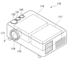
- It is a block diagram which shows the optical structure of a liquid crystal projector.
- liquid crystal display element 10 including an embodiment of the retardation plate of the present disclosure as a phase difference compensating element 20 will be described.
- the liquid crystal display element 10 is provided in, for example, a liquid crystal projector 110 (see FIGS. 39 and 40) described later.
- the liquid crystal display element 10 is a transmissive VA mode liquid crystal display element. That is, the liquid crystal layer of the liquid crystal display element 10 contains liquid crystal molecules that are oriented substantially perpendicular to the surface of the element in a no-voltage state. The liquid crystal display element 10 adjusts the voltage applied to the liquid crystal layer for each pixel to change the orientation of the liquid crystal molecules. As a result, the polarization state of the light transmitted through each pixel is controlled and an image is displayed.
- the liquid crystal display element 10 includes a polarizing element 15, a liquid crystal layer 17, and an analyzer 19 in this order from the light source side, and a phase difference compensating element 20 is provided between the liquid crystal layer 17 and the analyzer 19. Has been done.
- the polarizing element 15 is a polarizing plate that transmits only the polarized light component in the direction of the transmission axis T1 indicated by the arrow to the liquid crystal layer 17 side among the incident light. That is, the light incident on the liquid crystal layer 17 is only the incident light L0 in which the electric field vibrates in the direction parallel to the transmission axis T1.
- the analyzer 19 is a polarizing plate that transmits only the polarizing component in the direction of the transmission axis T2 indicated by the arrow among the light transmitted through the liquid crystal layer 17 and compensated for the phase difference by the phase difference compensating element 20.
- the detector 19 is arranged so that its transmission axis T2 is orthogonal to the direction of the transmission axis T1 of the polarizing element 15. That is, the analyzer 19 and the polarizing element 15 are arranged in a so-called cross Nicol. Therefore, the liquid crystal panel using the liquid crystal display element 10 is a normally black transmissive liquid crystal panel that displays black in a no-voltage state.
- the liquid crystal layer 17 is composed of transparent substrates 71 and 72 and rod-shaped liquid crystal molecules 75 enclosed between the transparent substrates 71 and 72.
- the transparent substrates 71 and 72 are composed of, for example, a glass substrate 77, a transparent electrode 78, an alignment film 79, and the like.
- the transparent substrate 71, the glass substrate 77, the transparent electrode 78, and the alignment film 79 are arranged in this order from the light source side.
- the alignment film 79, the transparent electrode 78, and the glass substrate 77 are arranged in order from the light source side.
- the transparent electrode 78 is connected to a TFT (Thin Film Transistor) circuit provided on the transparent substrate 71.
- This TFT circuit controls the orientation state of the liquid crystal molecules 75 by controlling the voltage between the transparent electrode 78 on the transparent substrate 71 and the transparent electrode 78 on the transparent substrate 72 which is a common electrode.
- the alignment film 79 is arranged so that the orientation direction thereof forms an angle of 45 degrees with the direction of the transmission axis T1 of the polarizing element 15.
- the liquid crystal molecules sandwiched between the pair of alignment films 79 are inclined and oriented according to the orientation direction of the alignment films 79.
- the liquid crystal molecule 75 is a rod-shaped liquid crystal molecule having negative dielectric anisotropy, and is oriented substantially perpendicular to the surface of the liquid crystal display element 10 in a no-voltage state. At this time, the liquid crystal molecules 75 do not substantially affect the phase of the light transmitted through the liquid crystal layer 17. That is, the light transmitted through the liquid crystal layer 17 in the non-voltage state passes through the liquid crystal layer 17 without changing its polarization direction.
- the information light L1 having substantially the same polarization direction as the incident light L0 is incident on the phase difference compensating element 20 from the liquid crystal layer 17. Since this information light L1 is light polarized in a direction perpendicular to the transmission axis T2 of the detector 19, it cannot pass through the detector 19. Therefore, by setting the pixels of the liquid crystal display element 10 to a non-voltage state, black color is displayed (hereinafter, dark display).
- the liquid crystal molecules 75 are tilted in the orientation direction of the alignment film 79. At this time, the liquid crystal molecule 75 changes the phase of the light transmitted through the liquid crystal layer 17 according to the inclination angle thereof. That is, the light transmitted through the liquid crystal layer 17 changes the polarization direction according to the inclination angle of the liquid crystal molecules 75.
- the polarizing component parallel to the transmission axis of the detector 19 transmits the detector 19. Therefore, by adjusting the pixels of the liquid crystal display element 10 to an appropriate voltage, the amount of light transmitted through the analyzer 19 is adjusted, and the intermediate gradation color is displayed.
- the phase difference compensating element 20 is provided between the liquid crystal layer 17 and the analyzer 19 as described above in order to compensate for the phase difference of the information light transmitted through the liquid crystal layer 17. Details of the phase difference compensating element 20 will be described later.
- the liquid crystal molecules 75 are oriented substantially perpendicular to the surface of the liquid crystal display element 10.
- the liquid crystal molecules 75 are intentionally tilted in advance by about 5 ° from the vertical direction even in a no-voltage state. This tilting arrangement is performed in order to suppress the occurrence of orientation defects of the liquid crystal molecules 75 called the reverse tilt domain.
- the reverse tilt domain is a disorder of the alignment state of the liquid crystal molecules 75 caused by the electric fields exerted between adjacent pixels.
- the Y2 axis and the Z2 axis are defined in a plane parallel to the surface of the liquid crystal display element 10, and the light transmitted through the liquid crystal layer 17 in the direction perpendicular to the surface of the liquid crystal display element 10.
- the X2 axis is defined with the traveling direction of light as positive in parallel with the light axis (transmitted light axis) L0. Further, the X2 axis and the Y2 axis are defined to be parallel to the transmission axes of the analyzer 19 and the polarizing element 15, respectively. Therefore, as shown in FIG. 2, the angle (azimuth) ⁇ formed by the tilt direction of the liquid crystal molecule 75 with the Y2 axis is 45 °.
- the angle formed by the liquid crystal molecule 75 with respect to the Y2-Z2 plane is the tilt angle ⁇ of the liquid crystal molecule 75.
- the tilt angle ⁇ changes in a range of about 0 ° or more and 85 ° or less depending on the magnitude of the voltage applied to each pixel.
- the tilt angle ⁇ is approximately 0 degrees, a sufficient voltage is applied to the liquid crystal layer 17, and the liquid crystal molecules 75 are oriented in parallel with the Y2-Z2 plane.
- the tilt angle ⁇ is 85 degrees, it is in a non-voltage state and the liquid crystal molecules 75 are oriented substantially perpendicular to the Y2-Z2 plane.
- the tilt angle ⁇ in this no-voltage state is the pre-tilt angle, and the liquid crystal molecule 75 is tilted about 5 ° with respect to the X2 axis, that is, the transmitted optical axis L0, along the orientation direction of the alignment film 79.
- phase advance axis F caused by the pre-tilt component of the liquid crystal molecules 75 in the liquid crystal layer 17 coincides with the pre-tilt direction.
- the phase-advancing axis F refers to an axis along an direction in which the refractive index is relatively low and the phase of light is relatively advanced in a medium that transmits light.
- the phase-advancing axis F due to the pretilt component of the liquid crystal molecule 75 in the liquid crystal layer 17 is simply referred to as the phase-advancing axis F of the liquid crystal layer 17.
- the phase difference compensating element 20 compensates for the phase difference of the information light transmitted through the liquid crystal layer 17 by generating a phase difference opposite to the phase difference generated in the liquid crystal display element 10. Therefore, the phase difference compensating element 20 is arranged so that the slow phase axis S of the phase difference compensating element 20 coincides with the phase advancing axis F due to the pretilt component of the liquid crystal layer 17.
- the slow-phase axis S which is the opposite of the phase-advance axis F, refers to an axis along an direction in which the refractive index is relatively high and the phase of light is relatively delayed in a medium that transmits light.
- the phase difference caused by the pretilt of the liquid crystal molecules 75 and the phase difference caused by the phase difference plate 21 are mutually arranged. Since the positive and negative directions are reversed, the phase difference caused by the pretilt of the liquid crystal molecule 75 can be compensated.
- phase difference plate 21 of the embodiment of the present disclosure can be applied.
- the retardation plate 21 of the first embodiment includes a glass substrate as an example of the substrate 23 and a retardation film 25 formed on one surface of the substrate 23.
- the retardation film 25 is an oblique film having a columnar structure 24 inclined with respect to the normal line N of the film forming surface 23a, which is one surface on which the retardation film 25 is formed.
- the retardation film 25 of this example is hereinafter referred to as an orthorhombic film 25.
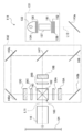
- the orthorhombic film 25 is produced by depositing an inorganic material such as Ta 2 O 5 on the substrate 23 from an oblique direction by a so-called orthorhombic vapor deposition method. Specifically, as shown in FIG. 4, the vapor deposition source is held on the film forming surface 23a of the substrate 23 in a state where the film forming surface 23a of the substrate 23 is held in an inclined posture with respect to the vapor deposition source 27. The thin-film deposition material from 27 is obliquely incident and vapor-filmed.
- the columnar structure is inclined according to the incident direction (hereinafter, referred to as the vapor deposition direction) 28 of the vapor-film-deposited substance on the film-forming surface 23a.
- the body 24 grows to form an oblique film 25 having a structure in which the columnar structure 24 stands.
- the angle formed by the vapor deposition direction 28 and the normal line N of the film forming surface 23a is referred to as the vapor deposition angle ⁇ .
- the substrate 23 is installed at an angle formed by the horizontal plane (a surface parallel to the horizontal floor surface) shown by the dotted line in FIG. 4 and the film forming surface 23a. It is called the angle ⁇ . That is, the installation angle ⁇ when the substrate 23 is installed horizontally is 0 °, and the installation angle ⁇ when the substrate 23 is installed perpendicular to the horizontal is 90 °.
- the longitudinal direction 29, which is the growth direction of the columnar structure 24 of the oblique film 25, generally does not match the vapor deposition direction 28 (see also FIG. 4), but the columnar structure 24 forms the film of the substrate 23.
- the growth angle ⁇ formed by the normal line N of the surface 23a has a positive correlation with the vapor deposition angle ⁇ . That is, when the vapor deposition angle ⁇ is large, the growth angle ⁇ of the columnar structure is large, and when the vapor deposition angle ⁇ is small, the growth angle ⁇ of the columnar structure is also small.
- the growth direction 29 of the columnar structure 24 tends to rise from the film forming surface 23a rather than the vapor deposition direction 28, and the growth angle ⁇ is smaller than the vapor deposition angle ⁇ ( ⁇ ⁇ ). Due to the columnar structure in which the columnar structure 24 stands, the retardation film 25 exhibits refractive index anisotropy as an optical characteristic and functions as an O plate.
- the growth direction 29 of the columnar structure 24 is the longitudinal direction of the columnar structure 24.
- the growth direction 29 is referred to as a longitudinal direction 29.
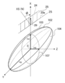
- the refractive index anisotropy of the oblique film 25 is conceptually represented by a refractive index ellipsoid 102 having three main refractive indexes nx, ny, and nz as axes.
- 6A is a view of the refractive index ellipsoid 102 viewed from the Y-axis direction in FIG. 5
- FIG. 6B is a view of the refractive index ellipsoid 102 viewed from the Z-axis direction in FIG.
- FIG. 6C is a view of the refractive index ellipsoid 102 as viewed from the X-axis direction in the figure.
- the main refractive index is the long axis of the refractive index of the refractive index ellipse and the length of the ellipse obtained by cutting the refractive index ellipse along the major axis. It means the refractive index in the direction of the first minor axis perpendicular to the axis and the refractive index in the direction of the second minor axis perpendicular to the major axis and the first minor axis.
- one of the three main refractive indexes nx, ny, and nz of the refractive index ellipsoid 102 forms an axis that coincides with the longitudinal direction 29 of the columnar structure 24.
- the axis corresponding to the longitudinal direction 29 of the columnar structure 24 is defined as the X axis
- the main refractive index along the X axis is defined as nx.
- the major axis direction of the ellipsoid 104 passing through the center C of the refractive index ellipsoid 102 and perpendicular to the X axis is defined as the Y axis
- the minor axis direction is defined as the Z axis.
- the main refractive index in the Y-axis direction is ny
- the main refractive index in the Z-axis direction is nz.
- the three main refractive indexes nx, ny, and nz satisfy the following conditional expression (1). ny>nx> nz (1)
- FIG. 7A shows the relationship between each axis of the refractive index ellipsoid 102 with respect to the film surface of the retardation plate 21 perpendicular to the incident direction of light with respect to the retardation plate 21 and the incident direction of light.
- the normal line N of the film forming surface 23a of the substrate 23 is set as the XS axis
- the YS axis and the ZS axis are set on the film forming surface 23a perpendicular to the XS axis.
- the axis obtained by projecting the Y axis of the refractive index ellipsoid 102 onto the film forming surface 23a is defined as the YS axis, and the direction orthogonal to the YS axis is defined as the ZS axis.
- the X-axis of the refractive index ellipsoid 102 is in the XS-ZS plane and is ⁇ -inclined from the XS axis.
- the ZS axis coincides with the axis obtained by projecting the X axis onto the film forming surface 23a.
- the refractive ellipsoid 102 When the refractive ellipsoid 102 is cut in a plane passing through the center C of the refractive ellipsoid 102 and parallel to the film forming surface 23a, its cross section corresponds to the major axis radius in the YS axis direction as shown in FIG. 7B.
- the ellipsoid 106 has a refraction factor nys and a refraction factor nzs corresponding to the minor axis radius in the ZS axis direction.
- the oblique film 25 exhibits birefringence having a refractive index of nys in the YS axis direction and a refractive index of nzs in the ZS axis direction with respect to light incident along the XS axis.
- This refractive index nys is larger than the refractive index nzs. That is, the retardation film 25 has a slow phase axis S1 in the YS axis direction, which has the maximum refractive index with respect to light incident from the XS axis direction.
- the retardation film 25 has a phase advance axis F1 in the ZS axis direction, which has a minimum refractive index with respect to light incident from the XS axis direction.
- the slow-phase axis S1 is orthogonal to the axis (ZS axis) obtained by projecting the X-axis corresponding to the growth direction 29 onto the film forming surface 23a. That is, it is the YS axis in which the Y axis corresponding to the maximum main refractive index ny of the three main refractive indexes ny is projected onto the film forming surface 23a, and the incident light corresponds to the main refractive index ny.
- the slow phase axis S1 is orthogonal to the ZS axis.
- FIG. 8A is a view of an ellipsoid 107 having a cross section cut along an XS-ZS plane passing through the center C of the ellipsoidal index 102 as viewed from the YS axis direction.
- FIG. 8B is a view of an ellipsoid 106 having a cross section obtained by cutting the refractive index ellipsoid 102 in the YS-ZS plane passing through the center C from the XS axis direction.
- FIG. 8C is a view of an ellipsoid 108 having a cross section obtained by cutting the refractive index ellipsoid 102 in the XS-YS plane passing through the center C from the ZS axis.
- the X-axis and Z-axis of the refractive index ellipsoid 102 showing the refractive index anisotropy of the retardation film 25 are rotated by ⁇ about the YS axis with respect to the XS-axis and ZS-axis of the retardation plate. There is.
- phase difference generated in the incident light changes depending on the inclination of the light incident on the refractive index ellipsoid 102.
- the phase difference that occurs in the refractive index ellipsoid 102 is a cross section perpendicular to the incident light, and depends on the difference between the major axis and the minor axis of the ellipse formed in the cross section that passes through the center C of the refractive index ellipsoid 102.
- the incident angle in the direction of tilting the columnar structure 24 toward the growth direction 29 with respect to the XS axis which is the normal line N of the oblique film 25 is positive (+ ⁇ )
- the columnar structure 24 Let the incident angle in the tilting direction be negative (- ⁇ ) on the side opposite to the growing direction.
- the phase difference Re (0) with respect to the light incident on the oblique film 25 along the XS axis, that is, the light incident at an incident angle of 0 ° is referred to as a front phase difference.
- the refractive index nys in the YS axis direction which is the long axis of the ellipse of the refractive index ellipse on the plane perpendicular to the XS axis, that is, the YS-ZS plane (see FIG. 8B).
- the oblique film 25 of the present embodiment has a ratio of the phase difference Re (+30) of the incident light having a negative incident angle of +30 ° and the phase difference Re (-30) of the incident light having a positive incident angle of ⁇ 30 °.
- the Re (30) ratio of a certain phase difference ratio satisfies the following conditional expression (2).
- the retardation plate 21 provided with the oblique film 25 as described above is such that the slow axis S1 of the oblique film 25 and the tilt direction of the liquid crystal molecules 75 are parallel to each other, that is, the liquid crystal. It is arranged so as to be parallel to the phase advance axis F due to the pretilt of the molecule 75.
- the retardation plate 21 is used as the phase difference compensating element 20
- the slow phase axis S1 of the oblique film 25 corresponds to the slow phase axis S in the phase difference compensating element 20.
- the phase difference caused by the pretilt of the liquid crystal molecule 75 and the phase difference caused by the retardation plate 21 are opposite to each other, so that the phase difference can be compensated.
- the pre-tilted liquid crystal molecules 75 are the cause of causing the phase difference, but also the diffraction of light, the polarizing element 15 and the analyzer due to the fine structure of the liquid crystal cell.
- the phase difference is caused by various factors such as the generation of the phase difference due to 19. Therefore, the retardation plate 21 may not always have the best arrangement in which the slow phase axis S1 and the phase advance axis F of the liquid crystal molecule coincide with each other.
- the azimuth angle at which high contrast can be obtained while observing the contrast of the projected image is rotationally adjusted around the XS axis so as to be.
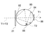
- the haze of the orthorhombic membrane 25 can be measured using an integrating sphere.
- the integrating sphere 80 includes an incident opening 82 and an exit opening 84 provided at a position facing the incident opening 82 and rotated by 180 ° from the incident opening 82.
- the photodetectors 86 and 88 are provided inside the exit opening 84 of the integrating sphere 80 and the integrating sphere 80, respectively.
- the photodetector 86 provided in the exit opening 84 receives the light that has traveled straight through the integrating sphere among the light incident along the diameter of the integrating sphere 80 from the incident opening 82.
- the photodetector 88 arranged in the integrating sphere 80 does not go straight among the incident light, but receives the scattered light reflected in the integrating sphere 80.
- the retardation plate 21 is arranged in the incident opening 82 so that the film surface is perpendicular to the light incident along the diameter.
- the incident light L is vertically incident on the film surface of the retardation plate 21, passes through the retardation plate 21, travels straight without being scattered by the retardation plate 21, and the photodetector measures the amount of vertically transmitted light T1 that reaches the exit aperture. Detect at 86.
- the photodetector 88 arranged in the integrating sphere detects the scattered light amount T2 that is scattered by the retardation plate 21 of the incident light L and repeatedly reflected in the integrating sphere 80 without going straight.
- the haze of the orthorhombic film 25 is obtained by measuring the haze of the substrate 23 alone by the above means and subtracting the haze of the substrate only from the haze of the retardation plate 21. When the substrate 23 is a glass substrate, the haze is almost zero.
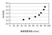
- the present inventor has a Re (30) ratio and a haze in an oblique film 25 having a refractive index anisotropy represented by a refractive index ellipsoid 102 in which the main refractive indexes nx, ny, and nz satisfy the above equation (1). It was found that there is a correlation with and as shown in FIG. When the Re (+30), Re (-30) and Re (30) ratios satisfy the above (2), the haze of the orthorhombic membrane 25 can be suppressed to 0.1% or less. By setting the Re (30) ratio to 4.0 or less, that is, by suppressing the haze to 0.1% or less, the Re (30) ratio is applied to the liquid crystal display element as the phase difference compensating element 20. The contrast can be improved as compared with the case where is more than 4.0.
- the orthorhombic film 25 satisfying the above equations (1) and (2) can be manufactured by adjusting the substrate installation angle ⁇ at the time of orthorhombic vapor deposition.
- a plurality of oblique films are produced by changing the substrate installation angle ⁇ with the vapor deposition source 27 placed directly under the center of the substrate 23, and the Re (30) ratio is set.
- the relationship shown in FIG. 12 was obtained.
- tantalum pentoxide (Ta 2 O 5 ) is used as the material of the orthorhombic membrane 25.
- the Re (30) ratio increases as the substrate installation angle ⁇ increases.
- a Re (30) ratio of 4.0 or less can be obtained by setting the substrate installation angle ⁇ to approximately 85 degrees or less.
- the relationship between the substrate installation angle ⁇ and the Re (30) ratio depends on the configuration of the vapor deposition apparatus, and the relationship between the Re (30) ratio and the substrate installation angle ⁇ shown in FIG. 12 changes depending on the vapor deposition apparatus.
- the tendency that the Re (30) ratio increases as the substrate installation angle ⁇ increases is common regardless of the configuration of the vapor deposition apparatus. Therefore, if the relationship between the two is measured in advance, the orthorhombic membrane 25 having a desired Re (30) ratio can be obtained.
- the Re (30) ratio preferably satisfies the following conditional expression (2-1).
- this conditional expression (2-1) the effect of improving the black display unevenness can be obtained in the retardation plate 31 (see FIG. 16) provided with two layers of the orthorhombic film 25, which will be described later.
- Re (30) ratio satisfies the following conditional expression (2-2).
- Re (30) ratio satisfies the following conditional expression (2-3).
- the material of the orthorhombic film 25 an oxide containing at least one of Si, Nb, Zr, Ti, La, Al, Hf and Ta can be used. That is, the orthorhombic film 25 can be composed of an oxide containing at least one of Si, Nb, Zr, Ti, La, Al, Hf and Ta. By using these materials, an orthorhombic membrane composed of a good columnar structure can be obtained.
- the method of forming the oblique film 25 is not limited to the above method. Any method may be used as long as the columnar structure 24 can be grown on the film forming surface 23a of the substrate 23 in the direction inclined from the normal line N to obtain the oblique film 25.
- the vapor deposition method is not limited to vacuum vapor deposition, and electron beam vapor deposition, ion plating, or the like can be used. Further, chemical vapor deposition (CVD) may be used. Further, a sputtering method, a reactive sputtering method and the like can also be used.
- the incident angle dependence of the retardation was as shown in FIG. 13
- the plane orthogonal to the incident light is considered in the refractive index ellipsoid 102.
- the YS-ZS plane is a plane orthogonal to the incident light in the refractive index ellipsoid 102 with respect to the light incident from the XS axis direction.
- the ZY plane is orthogonal to the light LX incident from the X-axis direction.
- the refractive index n ( ⁇ ) in the axial direction changes depending on the incident angle ⁇ .
- the phase difference with respect to the incident light passes through the center C of the refractive ellipsoid 102 and is proportional to the difference between the major axis radius and the minor axis radius of the ellipsoid of the refractive index ellipsoid 102 on the plane orthogonal to the incident light.
- the phase difference was measured by subtracting the refractive index n ( ⁇ ), which changes depending on the incident angle, from the reference refractive index nys with the refractive index nys as a reference.
- the phase difference increases as the incident angle ⁇ increases in the positive direction, and the phase difference becomes almost constant when the incident angle ⁇ is 30 ° or more.
- the phase difference decreases, and the incident angle ⁇ is 50 ° and the phase difference is 0.
- d2 d / cos ( ⁇ -90).
- a screen was placed at a position where light passing through the analyzer 19 was projected, white display and black display were performed on the screen, and contrast and black display unevenness were evaluated according to the following criteria, respectively.
- the slow axis of the orthorhombic film was aligned with the phase advance axis F caused by the pretilt component of the liquid crystal layer 17.
- the phase-advancing axis due to the pre-tilt component of the liquid crystal layer 17 in this example has a 45 ° azimuth, and the slow-phase axis S of the oblique film of the retardation plate is aligned with the 45 ° azimuth.
- the value of the illuminance at the time of white display when the illuminance of black display was set to 1 was measured, and the measured value was evaluated as follows.
- the black display: white display was 800: 1 when the phase difference compensating element 20 was not provided.
- Black display unevenness ((A + D)-(B + C)) / E Calculated as.
- the calculated value of black display unevenness was evaluated as follows. A: 2 or less B: 2 or more, 4 or less C: 4 or more, 6 or less D: 6 or more
- the A evaluation was 7 points
- the B evaluation was 5 points
- the C evaluation was 3 points
- the D evaluation was 0 points.
- the total score was obtained by adding the scores of display unevenness. The higher the total score, the better the quality of the retardation plate. The results are shown in Table 1 below.
- Samples 1-2 to 1-8 in which Re (30) shown in Table 1 is 1.1 to 4 correspond to the embodiment of the retardation plate of the present disclosure.
- the samples 1-2 to 1-8 have a higher contrast evaluation than the other samples, and the high contrast is improved.
- the total score of the contrast and the black display unevenness is high, and the effect of suppressing the black display unevenness is obtained while improving the contrast.
- the samples with Re (30) of 1.1 to 2.0 the effects of further improving the contrast and suppressing the black display unevenness are obtained.
- Phase difference plate of the second embodiment The retardation plate used as the phase difference compensating element 20 is not limited to the configuration in which only one oblique film 25 is provided as in the above retardation plate 21, but two or more oblique films 25 are laminated and provided. You may.
- the retardation plate of the second embodiment the retardation plate 31 provided with two layers of oblique films will be described.
- the retardation plate 31 of the present embodiment is provided with a first oblique film 25a on one surface of the substrate 23, and a second oblique film 25b is formed on the other surface. .. That is, in the retardation plate 31, the orthorhombic film is formed layer by layer on both sides of the substrate.
- the first orthorhombic film 25a and the second orthorhombic film 25b in the present embodiment are manufactured in the same manner as the above-mentioned orthorhombic film 25, and their optical properties and the like are also the same. That is, the first orthorhombic film 25a and the second orthorhombic film 25b are represented by a refractive index elliptical body 102 in which the main refractive indexes nx, ny, and nz satisfy the above equation (1), similarly to the oblique film 25. Has a refractive index anisotropy. Further, the Re (+30), Re (-30) and Re (30) ratios satisfy the above equation (2).
- the haze can be suppressed to 0.1% or less, respectively.
- the haze is integrated, so that the haze as the retardation plate 31 increases.
- the orthorhombic films 25a and 25b satisfy the above equations (1) and (2), the haze when laminated can be suppressed, and the haze when laminated can be reduced to 0.3% or less. (See FIG. 28 below).
- the retardation plate has a haze of 0.3% or less when two or more layers of oblique films 25a and 25b are provided, Re (30) is applied to the liquid crystal display element as the phase difference compensation element 20.
- the contrast can be improved and the black display unevenness can be suppressed as compared with the case where the ratio exceeds 4.
- the slow axis S21 of the first oblique film 25a and the slow axis S22 of the second oblique film 25b intersect at an intersection angle of 90 ° ⁇ 3 °, which is substantially orthogonal to each other.
- the first orthorhombic film 25a and the second orthorhombic film 25b are arranged therein.
- the slow axis S1 of the oblique film 25 and the phase advance axis F of the liquid crystal layer 17 are parallel to each other in the liquid crystal display element 10. It is arranged so that it becomes.
- the retardation plate 31 provided with the two layers of the oblique films 25a and 25b the slow axis S21 of the first oblique film 25a and the slow axis S22 of the second oblique film 25b are synthesized.
- the synthetic slow-phase axis S2 is arranged so as to be parallel to the phase-advancing axis F of the liquid crystal layer 17.
- the slow phase axis S21 of the first oblique film 25a is in the 90 ° direction. They are aligned and the slow axis S22 of the second oblique film 25b is arranged so as to coincide with the 0 ° direction.
- the combined slow-phase axis S2 which is a combination of the slow-phase axis S21 and the slow-phase axis S22, has a 45 ° direction and coincides with the phase-advancing axis F.
- the intersection angle of the slow axis of the first orthorhombic membrane 25a and the second orthorhombic membrane 25b will be examined. According to the studies by the present inventors, it is preferable that the crossing angle deviates slightly from 90 °. It is preferably deviated in the range of ⁇ 5 ° with respect to 90 °, and more preferably deviated in the range of ⁇ 3 °. The reason will be explained below.
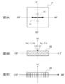
- the in-plane optical anisotropy of the orthorhombic film 25 will be described with reference to FIG.
- the axis obtained by projecting the vapor deposition direction 28 (see FIGS. 3 and 4) onto the film forming surface 23a (see FIG. 3) is orthogonal to the slow phase axis S1.
- the axis in which the vapor deposition direction 28 is projected onto the film forming surface 23a and the axis in which the growth direction 29 is projected on the film forming surface 23a coincide with each other.
- the phase advance axis F1 orthogonal to the slow phase axis S1 is defined as an orientation of 0 ° ⁇ 180 °.
- FIG. 18B is a cross section of the orthorhombic membrane 25 shown in FIG. 18A along the phase advance axis F1
- FIG. 18C is a cross section of the orthorhombic membrane 25 shown in FIG. 18A along the slow axis S1.
- the columnar structure 24 is inclined in a cross section along the phase advance axis F1. Therefore, even if the incident angle ⁇ is the same, if the incident direction is different, the phase difference that the light receives when passing through the columnar structure 24 is different.
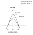
- the phase difference between the incident angle ⁇ and the azimuth angle ⁇ may be referred to as Re ( ⁇ ) ⁇ .
- the phase difference at an incident angle of 15 ° and an azimuth angle of 90 ° is Re (15) 90 °.
- phase difference Re ( ⁇ ) with respect to the incident light at the incident angle ⁇ inclined in the growth direction from the normal line described in FIG. 9 is Re ( ⁇ ) 180 according to this notation, which is the growth direction from the normal line.
- the phase difference Re ( ⁇ ) with respect to the incident light having an incident angle ⁇ tilted to the opposite side is Re ( ⁇ ) 0.
- the orientation of the liquid crystal display element 10 of this example is described in a single-layer oblique film in which the phase-advancing axis due to the pretilt of the liquid crystal molecules 75 of the liquid crystal layer 17 is defined as a 45 ° orientation. It is different from the above orientation.
- the orientation of the retardation plate 31 follows the orientation of the liquid crystal display element 10.
- the combined slow axis S21 of the first oblique film 25a and the second oblique film 25b and the combined slow axis S2 of S22 are oriented at 45 °. It is installed so that it becomes.
- the phase difference Re ( ⁇ ) between the first orthorhombic film 25a and the second orthorhombic film 25b has azimuth dependence, respectively.
- the phase difference Re ( ⁇ ) of the retardation plate 31 in which both are laminated is the sum of the phase differences between the first oblique film 25a and the second oblique film 25b.
- the liquid crystal layer 17 has a front phase difference component due to the pretilt component in the 45 ° direction, has a peak in the 45 ° direction, and exhibits a substantially symmetrical azimuth angle dependence in the range of ⁇ 45 °.
- the Re (0) 45 of the retardation plate 31 is zero, so that the liquid crystal layer 17 The front phase difference of is not compensated.
- the range of 45 ° azimuth ⁇ 45 ° in the retardation plate 31 That is, the azimuth dependence of the phase differences Re (0) and Re (15) in the 0 ° to 90 ° directions is schematically shown in FIG.
- the front phase difference Re (0) of the phase difference plate 31 shows an azimuth angle dependence having a peak in the 45 ° direction.
- the front phase difference Re (0) in the 45 ° direction is generated by about 0.1 nm to 5 nm so that the phase difference is about the same as the front phase difference in the phase-advancing axis direction of the liquid crystal layer 17. This makes it possible to satisfactorily compensate for the front phase difference of the liquid crystal layer in the 45 ° direction. That is, as the retardation plate 31, it is preferable that the front phase difference Re (0) in the slow phase axial direction is 0.1 nm to 5 nm.
- the retardation plate 31 provided by laminating the first and second two layers of the oblique films 25a and 25b has the crossing angle of the slow axis of each of the two layers of the oblique films 25a and 25b and the 45 ° direction.
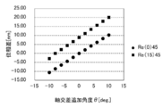
- the relationship between Re (0) 45 and Re (15) 45 of the retardation plate in FIG. 21 is as shown in FIG. 21 as an example.
- the case where the slow phase axes are orthogonal to each other is defined as 0 °
- the case where the crossing angle is larger than 90 ° is positive
- the crossing angle is smaller than 90 ° is negative.
- phase difference Re (0) of the phase difference plate 31 in the range of zero to ⁇ 10 nm by changing the slow phase axis by ⁇ 10 ° from the orthogonal state.
- phase difference Re (15) of the phase difference plate 31 also changes in the range of ⁇ 10 nm from the value (9 nm) in the orthogonal state.
- the crossing angle of the slow axes of the two layers of the oblique films 25a and 25b to be laminated may be set according to the front phase difference Re (0) of the liquid crystal layer 17 in the 45 ° direction of the liquid crystal display element 10 to be applied.
- the deviation of the crossing angle between the slow axes of the first orthorhombic film 25a and the second orthorhombic film 25b from 90 ° may be within ⁇ 5 °. It is preferably within ⁇ 3 °, and more preferably within ⁇ 3 °.
- the liquid crystal layer 17 has a front phase difference component due to the pretilt component in the 45 ° direction, has a peak in the 45 ° direction, and exhibits a substantially symmetrical azimuth angle dependence in the range of ⁇ 45 °.
- the phase difference Re ( ⁇ ) when incident at another incident angle ⁇ also has a peak in the 45 ° azimuth, and is dependent on a substantially symmetrical azimuth in the range of ⁇ 45 °. Show sex.
- the phase difference Re ( ⁇ ) of the retardation plate 31 is substantially symmetric with respect to the direction 45 ° in the range of 45 ° direction ⁇ 45 °.
- the difference between the phase difference Re (15) 90 in the 90 ° direction, which is 45 ° direction + 45 °, and the phase difference Re (15) 0 in the 0 ° direction, which is 45 ° direction ⁇ 45 °, is an index of symmetry. The smaller the difference, the higher the symmetry with respect to the direction of 45 °.
- the phase difference between the phase difference Re (15) 90 and the phase difference Re (15) 0 is preferably within ⁇ 6 nm.
- the phase difference Re ( ⁇ ) of the phase difference plate 31 shows a positive maximum peak in one direction of the combined slow phase axis S2.
- the orientation of the combined slow phase axis showing the maximum peak is arranged so as to coincide with the phase advance axis F of the liquid crystal layer 17.
- the retardation plate 31 has an azimuth angle at which the phase difference Re (15) generated with respect to the incident light having an incident angle of + 15 ° with respect to the normal line is maximized in the azimuth angle from 0 ° to 360 °. Is the reference azimuth angle ⁇ a.
- the retardation plate 31 is arranged so that the reference azimuth angle ⁇ a is 45 °. That is, the retardation plate 31 has the first phase difference Re (15) ⁇ a + 45 of the incident light when the azimuth is + 45 ° with respect to the reference azimuth angle ⁇ a, and the azimuth is ⁇ 45 ° with respect to the reference azimuth angle ⁇ a.
- the absolute value of the difference between the incident light and the second phase difference Re (15) ⁇ a-45 is preferably 6 nm or less.
- the difference between the phase difference Re (15) ⁇ a + 45 in the ⁇ a + 45 ° direction and the phase difference IRe (15) ⁇ a-45 in the ⁇ a-45 ° direction centered on the azimuth angle ⁇ a where the phase difference Re (15) is maximum is ⁇ 6 nm.
- the retardation plate 31 has high symmetry in the azimuth angle range of ⁇ a ⁇ 45 ° with the azimuth angle ⁇ a as the center. If the phase difference plate 31 has high symmetry in the azimuth angle range of ⁇ a ⁇ 45 ° with respect to the azimuth angle ⁇ a, then ⁇ 45 ° with respect to the azimuth of the phase advance axis of the liquid crystal layer having azimuth dependence.
- phase difference plate having a phase difference of opposite phases can be realized over a range.
- the phase difference in the range of the pretilt direction ⁇ 45 ° is the largest. Therefore, if the phase difference plate 31 shows the phase difference of the opposite phase over this range, the phase difference of the liquid crystal layer 17 can be obtained. It can be effectively compensated. Therefore, when such a phase difference plate 31 is applied as the phase difference compensating element 20 of the liquid crystal display element 10, the contrast can be effectively improved and black display unevenness can be suppressed.
- the refractive index anisotropy of both may not be completely the same.
- the difference ⁇ Re (0) of the front phase difference Re (0) between the first oblique film 25a and the second oblique film 25b is 3 nm or less.
- the orientation (peak orientation) at which the IRe (15) of the retardation plate 31 is maximum has a relationship as shown in FIG. 22 as an example.
- I is the phase difference of the retardation plate 31, and is added to distinguish it from the phase difference of each of the orthorhombic films 25a and 25b.
- FIG. 22 shows the results of investigating the relationship between ⁇ Re (0) and IRe (15) peak orientation.
- ⁇ Re (0) when ⁇ Re (0) is zero, the IRe (15) peak direction coincides with the 45 ° direction, which is the phase advance axis direction due to the pretilt component of the liquid crystal layer 17.
- ⁇ Re (0) when ⁇ Re (0) is smaller than zero, the IRe (15) peak direction becomes large, and when ⁇ Re (0) becomes larger than zero, the IRe (15) peak direction becomes small.
- the efficiency of phase difference compensation may decrease due to the deviation of the IRe (15) peak direction from the 45 ° direction.
- ⁇ Re (0) and the peak value IRe (15) max of the phase difference IRe (15) of the phase difference plate 31 in the 0-360 ° direction have a relationship as shown in FIG. 23.
- IRe (15) max is the smallest at about 9 nm when ⁇ Re (0) is zero.
- IRe (15) max increases. In this case, overcompensation of the phase difference may occur, and the efficiency of the phase difference compensation may decrease.
- ⁇ IRE (0) and ⁇ IRE (15) which is the difference between ⁇ Re (0) and IRe (15) at the orientation ⁇ 45 ° of the combined slow axis S2 in the retardation plate 31, that is, the difference between IRe (15) 90-IRE (15) 0. It has a relationship as shown in FIG. 24 with 15).
- ⁇ IRE (15) is close to 0 means that the symmetry in the range of ⁇ 45 ° is high around the direction of the synthetic slow phase axis S2.
- a large phase difference occurs in the range of ⁇ 45 ° in the direction of the phase advance axis F due to the pretilt component.
- phase difference generated in the liquid crystal layer 17 is symmetrical in the range of ⁇ 45 ° with respect to the direction of the phase advance axis F. Therefore, it is considered that the higher the symmetry of the phase difference plate 31 in the range of ⁇ 45 ° with respect to the direction of the combined slow phase axis S2, the higher the efficiency of the phase difference compensation.
- the IRe (15) peak direction is in the vicinity of the 45 ° direction, and the symmetry is high in the range of the 45 ° direction ⁇ 45 °. Is preferable. Therefore, the ⁇ Re (0) of the frontal phase difference between the two layers of the oblique films 25a and 25b is preferably within ⁇ 3 nm, preferably within ⁇ 1 nm, and the difference in the frontal retardation is 0. Most preferred.
- FIGS. 25 to 32 An example of design change for a retardation plate provided with two layers of oblique films will be described with reference to FIGS. 25 to 32.
- FIGS. 16 and 25 to 32 the same elements are designated by the same reference numerals.
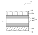
- antireflection films 41 and 42 are provided on both sides of the substrate 23, and a first oblique plate which is the outermost surface of the retardation plate 31 is provided. It is preferable to provide the antireflection films 43 and 44 on one surface of the square film 25a and one surface of the second oblique film 25a, respectively. By providing the antireflection films 41, 42, 43, 44, it is possible to suppress the reflection of the incident light at each interface, increase the transmittance, and further enhance the haze suppressing effect.
- the retardation plate 31 of the second embodiment is provided with the first oblique film 25a on one surface of the substrate 23 and the second oblique film 25b on the other surface.
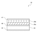
- two layers of orthorhombic films 25a and 25b may be formed on one side of the substrate 23 as in the retardation plate 32 shown in FIG. 26.
- the orthorhombic films 25a and 25b are provided on both sides of the substrate 23, respectively, the scattering at the interface caused when the orthorhombic films 25a and 25b are directly laminated can be suppressed. It is possible, and as a result, haze can be suppressed, which is preferable.
- both sides of the substrate 23 and the second oblique film 25b which is the outermost surface of the retardation plate 32 are formed. It is preferable that the antireflection films 45, 46, and 47 are provided on one surface, respectively. By providing the antireflection films 45, 46, and 47, it is possible to suppress the reflection of incident light at the interface, increase the transmittance, and further enhance the haze suppressing effect.
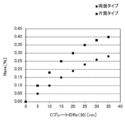
- FIG. 12 shows the relationship between the haze and the substrate installation angle ⁇ .
- the second oblique film 25b is formed in a state where the substrate is rotated by approximately 90 °, and the first oblique film 25b is formed.
- the slow axes S21 and S22 of the orthorhombic membrane and the second orthorhombic membrane are substantially orthogonal to each other (see FIGS. 16 and 26). Further, both sides of the substrate and the outermost surface of the retardation plate are provided with any of the antireflection films 41 to 47 (see FIGS. 25 and 27).
- the numerical values shown in parentheses are the Re (30) ratios for the single membrane orthorhombic membrane 25. As shown in FIG. 28, when the Re (30) ratio is 4 or less, the haze can be suppressed to about 0.3% or less. Further, from FIG. 28, the retardation plate 31 formed by distributing the orthorhombic films 25a and 25b to both sides of the substrate is compared with the retardation plate 32 in which two layers are laminated on one side, whichever Re (30) is used. Even in the ratio, the haze is kept low.
- the haze can be suppressed to about 0.2% or less if the Re (30) ratio is 4 or less.
- the two layers of the orthorhombic films 25a and 25b are directly contacted and laminated, and the two layers of the orthorhombic films 25a and 25b are laminated. It is considered that the effect of suppressing the scattering generated at the interface of the above is shown.
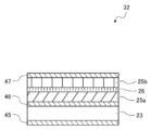
- the retardation plate 32 provided by laminating two layers of the oblique films 25a and 25b on one surface, as shown in FIG. 29, the first oblique film 25a and the second oblique film 25b are provided. It is preferable to provide a flattening layer 26 in between.
- the flattening layer 26 is an example of an intermediate layer.
- the flattening layer 26 has a function of flattening fine irregularities generated on the surface of the first oblique film 25a formed earlier.
- the flattening layer 26 not only the silicon oxide film (SiO 2 ) but also a metal oxide such as tantalum pentoxide (Ta 2 O 5 ) or magnesium fluoride (Mg F 2 ) can be used.
- the flattening layer 26 is formed, for example, by arranging a vapor deposition source directly under the substrate and performing front vapor deposition instead of oblique vapor deposition.
- the flattening layer 26 between the first orthorhombic film 25a and the second orthorhombic film 25b By providing the flattening layer 26 between the first orthorhombic film 25a and the second orthorhombic film 25b, the fine irregularities on the surface of the first orthorhombic film 25a are flattened, and the second The orthorhombic film 25b can be formed into a flat surface.
- the flattening layer 26 on the surface of the first oblique film 25a and reducing the surface roughness of the film forming surface of the second oblique film 25b, scattering at the interface is suppressed. Therefore, the haze in the retardation plate 32 can be suppressed. Further, as compared with the case where the second oblique film 25b is directly formed on the first oblique film 25a, the effect of improving black display unevenness and contrast is high.
- FIG. 30 shows the relationship between the haze and the substrate installation angle ⁇ for the retardation plate 32 (see FIG. 29) in which the flattening layer 26 having a silicon oxide film of 15 nm is provided between the orthorhombic films 25a and 25b.
- the data for the retardation plate 32 provided with the flattening layer 26 is indicated by a black triangular marker.
- FIG. 30 shows the data shown in FIG. 28 at the same time for comparison.
- the retardation plate 31 provided with the flattening layer 26 between the orthorhombic films 25a and 25b has the orthorhombic films 25a and 25b. It is possible to significantly reduce the haze as compared with the retardation plate 32 which is laminated by contacting the two.
- the Re (30) ratio is 4 or less, the haze can be suppressed to approximately 0.25% or less.
- the suitable film thickness of the flattening layer 26 was examined as follows.
- SiO 2 , Ta 2 O 3 or Mg F 2 was used as the flattening layer 26, and samples were prepared in which the film thickness was changed from 5 nm to 30 nm, respectively.
- an orthorhombic membrane having a Re (30) ratio of 2.0 was used.
- the refractive index is a value for a wavelength of 400 nm.
- the thickness of the flattening layer 26 is preferably such that the optical path length is about 40 nm, that is, about 1/10 or less with respect to the wavelength of 400 nm. Further, by setting the physical film thickness to 10 nm or more, the effect of flattening the film surface of the orthorhombic film and suppressing scattering can be enhanced.
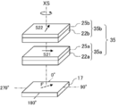
- a phase plate having two substrates on which the two orthorhombic films are formed may be used.
- the retardation plate 35 may be formed by stacking the retardation plates 35b.
- the embodiment in which two or more orthorhombic films are laminated is not only the embodiment in which a plurality of orthorhombic films 25a and 25b are laminated on one substrate 23, but also different substrates 22a.
- the present invention includes an embodiment in which the orthorhombic films 25a and 25b formed on the 22b are superposed on the optical path.
- the rotation angles of the phase advancing axes S31 and S32 are rotated by rotating one to the center of the XS axis at the time of assembly according to the liquid crystal display element 10 to be applied. Can be changed.
- the phase difference Re (0) and Re (15) of the liquid crystal layer 17 having manufacturing variations can be individually compensated for the phase difference most efficiently, that is, the contrast performance is maximized. It becomes possible to correspond to.
- the liquid crystal display element 10 provided with the liquid crystal layer 17 and the phase difference compensating element 20, at least one of the plurality of substrates 22a and 22b on which at least one retardation film is formed is formed.
- the contrast of the liquid crystal display element 10 can be adjusted by rotating the liquid crystal display element 10 with respect to the other substrate 22a about the XS axis perpendicular to the surface.
- the retardation plate of the present disclosure may have three or more layers of the orthorhombic film 25 laminated.
- a retardation plate 36 having the orthorhombic films 25a and 25b on one surface of the substrate 23 and the orthorhombic films 25c on the other surface is used as the retardation compensating element 20. You can also do it.
- the retardation plate 36 is provided with antireflection films 41, 42, 43, 44 on both sides of the substrate 23 and on the outermost surface of the retardation plate 36, respectively.
- the slow axis S21 of the first oblique film 25a In the case of the retardation plate 36 in which the oblique film 25 has three layers, the slow axis S21 of the first oblique film 25a, the slow axis S22 of the second oblique film 25b, and the third oblique film 25c.
- the slow phase axis S3 formed by synthesizing the slow phase axis S23 is arranged so as to be parallel to the phase advance axis F of the liquid crystal layer 17.
- the positive and negative of the phase difference caused by the pretilt of the liquid crystal molecule 75 and the phase difference caused by the retardation plate 36 are opposite to each other, so that the phase difference caused by the pretilt can be compensated.
- the slow axis S21 of the first oblique film 25a and the delay axis S of the second oblique film 25b are delayed.
- the first oblique film 25a and the second oblique film 25b are arranged so that the synthetic slow axis S2 of the phase axis S22 is oriented at 0 °.
- the third orthorhombic film 25c is arranged so that its slow phase axis S23 is oriented at 90 °.
- the synthetic slow axis S3 which is obtained by further synthesizing the synthetic slow axis S2 and the slow phase axis S23, can be made to match the direction of the phase advance axis F of the tilt component of the liquid crystal layer 17.
- the same phase difference compensation as when two layers of oblique films 25a, 25b are provided can be performed.
- the symmetry of the two layers of orthorhombic films centered on the 45 ° azimuth at 45 ° azimuth ⁇ 45 ° in the azimuth dependence of the phase difference as a retardation plate. It tends to be lower than that of the retardation plate.
- the azimuth dependence of the phase difference due to the pretilt component of the liquid crystal layer is symmetric about the 45 ° azimuth within the range of 45 ° azimuth ⁇ 45 °. Decreases. Therefore, in order to obtain high symmetry, it is preferable to use two layers of the orthorhombic membrane.
- the contrast plate 36 has a symmetry in which the phase difference between the phase difference Re (15) 90 and the phase difference Re (15) 0 is within ⁇ 6 nm.
- the effect of phase difference compensation can be obtained, and when applied to a liquid crystal display element, it is possible to increase the contrast and suppress black display unevenness.
- Samples 2-2 to 2-11 shown in Table 3 correspond to the examples of the retardation plate of the present disclosure.
- the sample of the example in which Re (30) is 1.2 to 4 has a higher evaluation of contrast than the sample in which Re (30) exceeds 4, and improvement in high contrast is achieved.
- higher contrast and black display unevenness suppression effects can be obtained with samples with Re (30) of 1.4 to 3.0, and further with samples with Re (30) of 1.5 to 2.5. A high effect was obtained.
- Samples 3-1 to 3-13 of the retardation plate having the layer structure shown in FIG. 27 were prepared.
- An orthorhombic film having a front retardation Re (0) of 23 nm was laminated and formed on one surface of a glass substrate having antireflection films on both sides by oblique vapor deposition.
- an antireflection film was formed on the surface of the second layer of the orthorhombic film.
- Ta 2 O 5 was used as the material for the orthorhombic membrane.
- the vapor deposition angle was changed by changing the mounting angle ⁇ of the substrate, and retardation plate samples 3-1 to 3-13 having different Re (30) ratio oblique films were prepared.
- the orthorhombic films laminated in one sample have the same Re (30) ratio.
- Samples 3-2 to 3-11 in which Re (30) shown in Table 4 is 1.2 to 4 correspond to the embodiment of the retardation plate of the present disclosure.
- the sample of the example has a high total score as compared with the sample having Re (30) of 4 or more. Further, the sample having a Re (30) of 1.4 to 4 has a higher contrast than the sample having a Re (30) ratio of more than 4. Higher overall evaluation is obtained for samples with Re (30) of 1.4 to 2.5, and contrast improvement effect and black display unevenness are obtained for samples with Re (30) of 1.5 to 2.3. Higher effect was obtained.
- Samples 4-1 to 4-13 were evaluated for contrast and black display unevenness by the same method as in Test Example 1, and scored. The results are shown in Table 5.
- Samples 4-2 to 4-11 in which Re (30) shown in Table 5 is 1.2 to 4 correspond to the embodiments of the retardation plate of the present disclosure.
- the sample of the example has a higher total score as compared with the sample having Re (30) of 4 or more. Further, in the sample having Re (30) of 1.4 to 3, a higher total score is obtained. Further, in the sample having Re (30) of 1.5 to 2.5, a higher effect was obtained in the contrast improving effect and the black display unevenness.
- phase difference IRe (15) ⁇ a + 45 in the ⁇ a + 45 ° direction centering on the direction ⁇ at which the phase difference IRe (15) is maximum, and the position in the ⁇ a ⁇ 45 ° direction.
- the effect that the difference from the phase difference IRe (15) ⁇ a-45 is within ⁇ 6 nm will be described.
- the contrast of each sample was measured in the same manner as in Test Example 1.
- the contrast of each sample was evaluated as follows, using the contrast when the retardation plate was not provided as the reference contrast.
- the contrast improvement rate of 1.5 times or more was obtained when ⁇ Re (15) ⁇ a was 6 nm or less in both the case where two layers of the orthorhombic film were laminated and the case where three layers were laminated.
- ⁇ Re (15) ⁇ a was 1 nm to 5 nm, the improvement rate of contrast was more than doubled, and when ⁇ Re (15) ⁇ a was 3 nm to 4 nm, the improvement rate was more than three times.
- Phase difference plate of the third embodiment In the above, the retardation plate provided by laminating one layer or two or more layers of the orthorhombic film has been described, but the retardation plate may be further provided with a C plate as well as the orthorhombic film. As the retardation plate of the third embodiment, an example of the retardation plate 37 provided with the C plate will be described.
- the retardation plate 37 of the present embodiment includes a substrate 23, a C plate 50, oblique films 25a and 25b, and antireflection films 48 and 49.
- the C plate 50 includes a first portion C plate 50a provided on both sides of the substrate 23 and a second portion C plate 50b.
- the first oblique film 25a is provided on the first portion C plate 50a
- the antireflection film 48 is provided on the first oblique film 25a.
- the second oblique film 25b is provided on the second portion C plate 50b
- the antireflection film 49 is provided on the second oblique film 25b.
- the C plate 50 is composed of a multilayer film in which a high refractive index layer 51 having a relatively high refractive index and a low refractive index layer 52 having a relatively low refractive index are alternately laminated.
- the C plate 50 does not show a phase difference for light vertically incident in the plane, that is, light incident at an incident angle of 0 °, but shows a phase difference for obliquely incident light having an incident angle other than 0. It has the refractive index anisotropy that it produces.
- FIG. 35 shows the phase difference characteristics for the light incident on the C plate 50 at incident angles of 0 °, 10 ° and 15 °.
- the phase difference Re (0) with respect to the light incident at an incident angle of 0 ° is 0 nm.
- the phase difference Re increases as the incident angle increases.
- the phase difference Re ( ⁇ ) has no azimuth dependence and is constant at an azimuth angle of 0 to 360 °.
- the value of the phase difference Re (15) is determined by the refractive index difference between the high refractive index layer and the low refractive index layer constituting the C plate and the number of layers.
- the C plate preferably has a haze of 0.4% or less.
- the haze in the retardation plate is the sum of the haze of the orthorhombic film and the haze of the C plate.
- the haze of the C plate By setting the haze of the C plate to 0.4% or less, the haze of the retardation plate can be suppressed, and when applied as a phase difference compensation plate of a liquid crystal display element, the contrast is improved and the black display unevenness is achieved. Can be suppressed.
- the haze of the retardation plate 37 is preferably 1% or less.
- the haze increases as a whole, but if the haze as the retardation plate 37 is suppressed to 1% or less, the contrast improvement effect and black display unevenness can be achieved. A sufficient inhibitory effect can be obtained.
- the synthetic slow phase axis S2 is arranged so as to coincide with the phase advance axis F of the liquid crystal layer 17.
- the phases of the two are opposite to each other, the phase difference generated in the liquid crystal layer 17 can be compensated by the retardation plate 31.
- the absolute value of the phase difference in the phase-advancing axis direction of the liquid crystal layer 17 and the phase difference in the slow-phase axis direction of the phase difference plate 31 match, the phase difference in the phase-advancing axis direction of the liquid crystal layer is satisfactorily compensated. can do.
- the phase difference in the 45 ° direction of the liquid crystal layer 17 and the phase in the 45 ° direction of the retardation plate 31 are opposite and the position is If the absolute values of the phase differences match, the phase difference in the 45 ° direction can be compensated even better.
- the two layers of the oblique films 25a and 25b are arranged with their slow phase axes S21 and S22 slightly offset from the orthogonal ones.
- the slow phase axes S21 and S22 By shifting the slow phase axes S21 and S22 from orthogonal to each other, the symmetry centered on the 45 ° azimuth of the azimuth dependence of the phase difference in the retardation plate 31 is shifted. Therefore, if the phase value of the phase difference Re (15) due to the pretilt component of the liquid crystal layer 17 and the Re (15) of the phase difference plate 31 in the 45 ° direction are matched, there is a possibility that an overcompensated direction may occur in other directions. There is.
- phase difference in the 15 ° incident angle 45 ° direction of the liquid crystal layer is A and the phase difference in the 15 ° incident angle 45 ° direction of the retardation plate 31 is B
- a ⁇ B is set and the difference BA is set.
- It is preferable to compensate with the phase difference C ( BA) of the C plate.
- the phase difference A in the synthetic slow axis orientation when the orthorhombic films are laminated depends on the Re (30) ratio of the orthorhombic films and increases as the Re (30) ratio increases.
- the haze tends to increase as the Re (30) ratio of the orthorhombic membrane increases.
- the phase difference of the C plate depends on the film thickness, and in order to increase the phase difference, it is necessary to increase the number of laminated multilayer films and increase the film thickness as a whole. As the film thickness of the C plate increases, the haze tends to increase, and the manufacturing cost increases and the manufacturing suitability decreases.
- the Re (30) ratio to 1.1 to 4.0 and combining it with the C plate, it is possible to achieve both the effect of suppressing haze and the manufacturing suitability of the C plate.
- the first portion C plate 50a may be provided on one surface of the substrate 23 and the second portion C plate 50b may be provided on the other surface as in the retardation plate 37 of FIG. Then, as shown in FIG. 37, the C plate 50 may be formed on one side of the substrate 23. Further, the C plate 50 preferably has an antireflection function.
- the antireflection function can be incorporated in each of the multilayer films constituting the first portion C plate 50a, the second portion C plate 50b, and the C plate 50. It is not necessary to separately provide an antireflection film between the substrate 23 and the C plate 50 and between the C plate 50 and the orthorhombic film 25, and the retardation plate 37 can be made thinner.
- the relationship between the haze and the phase difference Re (30) of the C plate was investigated.
- Samples were prepared for the double-sided type C plate and the single-sided type C plate with a layer structure in which Re (30) was 0 to 35 nm, respectively.
- the C plate was an alternating multilayer film in which the high refractive index layer was an Nb 2 O 5 layer and the low refractive index layer was a SiO 2 layer. Both the double-sided type and the single-sided type have an antireflection function by adjusting the film thickness of each layer in the multilayer film constituting the C plate and the overall layer structure.
- FIG. 38 shows the results of haze measurement for each sample.
- the double-sided type was able to suppress the haze lower in any of the Re (30). That is, from the viewpoint of haze suppression, when the C plate is provided in the retardation plate, it is preferable to distribute and form the C plate on both sides of the substrate.
- Nb niobium oxide (Nb 2 O 5 )
- Si silicon oxide (SiO 2 ), respectively.
- Table 7 shows the layer structure of the double-sided type C plate.
- the haze of the double-sided type C plate provided with a total of two layers of the front multilayer film was 0.2%.
- Table 8 shows a layer structure of a type C plate on one side.
- the haze of the single-sided type C plate provided with the multilayer film of Table 8 was 0.35%.
- Samples 6-2 to 6-11 shown in Table 9 correspond to the embodiments of the retardation plate of the present disclosure.
- the sample having Re (30) of 1.2 to 4 in the examples has a higher evaluation of contrast than the sample having Re (30) of more than 4, and the contrast is improved. Further, in the sample having Re (30) of 1.5 to 2.5, a very high contrast and an effect of suppressing black display unevenness can be obtained, and the manufacturing suitability of the C plate is excellent.
- the effect of improving the contrast can be obtained as compared with the case where the difference exceeds ⁇ 3 nm. be able to.
- the effect of improving the contrast can be further achieved in the range of ⁇ Re (0) of ⁇ 1 nm.
- the contrast improvement effect can be further achieved in the range of ⁇ Re (0) of ⁇ 2 nm, and the contrast improvement effect can be further achieved in the range of ⁇ Re (0) of ⁇ 1 nm.
- the azimuth angle is the reference azimuth angle ⁇ a for the retardation plate in which two or more layers of the retardation films are laminated.
- the absolute value of the difference from ⁇ 45 is preferably 6 nm or less.
- phase difference plates 21, 31, 32, 35, 36, 27 of the described embodiments can be applied to the liquid crystal display element 10 as the phase difference compensating element 20.
- the liquid crystal projector 110 provided with the liquid crystal display element will be described below.
- the liquid crystal projector 110 of the present disclosure includes a projection lens 116, a projector drive unit 117, and a display optical system 118.
- the projector 110 is provided with a zoom dial 121, a focus dial 122, a light amount adjustment dial 123, and the like on the upper surface of the housing 119. Further, on the back surface of the housing 119, a connection terminal (not shown) for connecting to an external device such as a computer is provided.
- the projection lens 116 magnifies the projected light incident from the display optical system 118 and projects it on the screen 124 (see FIG. 40).
- the projection lens 116 is composed of, for example, a zoom lens, a focus lens, an aperture, and the like.
- the zoom lens and the focus lens are provided so as to be movable along the projection optical axis L11.
- the zoom lens moves according to the operation of the zoom dial 121 to adjust the display magnification of the projected image.
- the focus lens moves according to the movement of the zoom lens or the operation of the focus dial 122 to adjust the focus of the projected image.
- the diaphragm adjusts the brightness of the projected image by changing the area of the diaphragm opening according to the operation of the light amount adjusting dial 123.
- the projector drive unit 117 controls the electrical operation of each unit of the projector 110.
- the projector drive unit 117 receives image data or the like from a computer or the like connected to the projector 110 and displays it on a liquid crystal display element described later.
- the projector drive unit 117 includes motors for driving each unit of the projection lens 116, and drives each of these motors in response to operations such as the zoom dial 121, the focus dial 122, and the light intensity adjustment dial 123.
- the display optical system 118 decomposes the light emitted from the light source into red light, green light, and blue light, and transmits the light to the liquid crystal display elements 10A, 10B, and 10C (see FIG. 2) that display information of each color, respectively. Generates information light of each color. Then, these information lights are combined into projected light, which is projected onto the screen 124 via the projection lens 116.
- the display optical system 118 includes a light source unit 131, an information light generation unit 132 that generates information light from the light emitted by the light source unit 131, and the like.
- the light source unit 131 is composed of a lamp 133, a reflecting mirror 134, an ultraviolet cut filter 136, an integrator 137, a polarizing plate 138, a relay lens 141, a collimating lens 142, and the like.
- the lamp 133 is a high-intensity light source such as a xenon lamp, and emits natural white light having no specific polarization direction.
- the white light emitted from the lamp 133 passes through the ultraviolet cut filter 136 and is incident on the integrator 137.
- the ultraviolet cut filter 136 removes ultraviolet light from the white light emitted from the lamp 133, and the white light causes deterioration of various filters (not shown) made of an organic polymer polymer or the like to be brown or the like. To prevent.
- the reflecting mirror 134 is, for example, an elliptic curved mirror, and a lamp 133 is provided in the vicinity of one focal point of the elliptic curved surface. Further, one end of the integrator 137 is provided in the vicinity of the other focal point. As a result, the white light emitted from the lamp 133 is efficiently guided to the integrator 137.
- the integrator 137 is composed of, for example, a glass rod and a microlens array provided on the end face of the glass rod, collects white light emitted from the lamp 133, and collects white light emitted from the lamp 133 to the collimating lens 142 via the relay lens 141. To lead.
- the amount of light incident on the integrator 137 from the lamp 133 decreases as the distance from the light source optical axis L12 increases, and the light is unevenly distributed around the light source optical axis L12. Therefore, the integrator 137 distributes the light having such a non-uniform light amount distribution substantially uniformly within a predetermined range centered on the light source optical axis L12. As a result, the projected image has substantially uniform brightness over the entire surface of the screen 124.
- the collimating lens 142 adjusts the light emitted from the integrator 137 to the light parallel to the light source optical axis L12.
- the polarizing plate 138 converts unpolarized light incident from the collimating lens 142 into linearly polarized light having a polarizing component (hereinafter, S-polarizing component) perpendicular to the paper surface. Then, the light of the S-polarized light component is guided to the information light generation unit 132 via the reflector 143a.
- the information light generation unit 132 includes a dichroic mirror 146, 147, a liquid crystal display element 10A, 10B, 10C, a phase difference compensation element 20A, 20B, 20C, a dichroic prism 61, and the like.
- the dichroic mirror 146 is provided so that the angle between the normal direction of the surface thereof and the optical axis of the incident light is 45 °. Further, the dichroic mirror 146 transmits the red light component of the S-polarized white light incident from the light source unit 131 and guides it to the reflecting mirror 143b. The reflecting mirror 143b reflects the red light transmitted through the dichroic mirror 146 toward the liquid crystal display element 10A.
- the dichroic mirror 146 reflects the green light component and the blue light component of the S-polarized white light incident from the light source unit 131 toward the dichroic mirror 147.
- the dichroic mirror 147 is provided so that the angle between the normal direction of the surface thereof and the optical axis of the incident light is 45 degrees. Further, the dichroic mirror 147 reflects the green light component of the S-polarized light incident from the dichroic mirror 146 toward the liquid crystal display element 10B.
- the dichroic mirror 147 transmits the blue light component of the S-polarized light incident from the dichroic mirror 146 and guides it to the reflecting mirror 143c. This blue light component is reflected by the reflecting mirror 143c and the reflecting mirror 143d, and is incident on the liquid crystal display element 10C.
- the liquid crystal display element 10A is the liquid crystal display element 10 shown in FIG.
- the liquid crystal display element 10A is driven by the projector drive unit 117, and displays the red component in the projected video data received from a computer or the like in gray scale. By transmitting through the liquid crystal display element 10A, the red light becomes red information light having information on the red component of the projected image.
- the liquid crystal display element 10B is the liquid crystal display element 10 shown in FIG. 1, and displays the green component in the projected video data received from a computer or the like in gray scale. By transmitting through the liquid crystal display element 10B, the green light becomes green information light having information on the green component of the projected image.
- the liquid crystal display element 10C is the liquid crystal display element 10 shown in FIG. 1, and displays the blue component in the projected video data received from a computer or the like in gray scale. By transmitting through the liquid crystal display element 10C, the blue light becomes blue information light having information on the blue component of the projected image.
- the phase difference compensating element 20A compensates for the phase difference of the red information light incident on the dichroic prism 160 from the liquid crystal display element 10A. That is, the phase difference compensating element 20A compensates for the phase difference caused by the pretilt of the liquid crystal molecules.
- phase difference compensating element 20B compensates for the phase difference of the green information light incident on the dichroic prism 160 from the liquid crystal display element 10B
- phase difference compensating element 20C is incident on the dichroic prism 160 from the liquid crystal display element 10C. Compensates for the phase difference of blue information light.
- the dichroic prism 160 is manufactured in a substantially cubic shape using a transparent material such as glass, and has dichroic surfaces 162 and 163 orthogonal to each other inside.
- the dichroic surface 162 reflects red light and transmits green light.
- the dichroic surface 163 reflects blue light and transmits green light.
- the dichroic prism 160 synthesizes red, green, and blue information lights incident from the liquid crystal display elements 151, 152, and 153 to form projected light, guides the light to the projection lens 116, and projects the image on the screen 124. Is displayed in full color.
- the retardation plates of the present disclosure for example, the retardation plates 31, 32, 33, 36, or 37 described above are used as the phase difference compensating elements 20A, 20B, 20C to pretilt the liquid crystal molecules. It is possible to efficiently compensate for the phase difference caused by the above. As a result, it is possible to obtain a projected image in which the contrast is improved as compared with the conventional case and the black display unevenness is suppressed.
Landscapes
- Physics & Mathematics (AREA)
- Nonlinear Science (AREA)
- General Physics & Mathematics (AREA)
- Optics & Photonics (AREA)
- Mathematical Physics (AREA)
- Chemical & Material Sciences (AREA)
- Crystallography & Structural Chemistry (AREA)
- Polarising Elements (AREA)
- Liquid Crystal (AREA)
Abstract
L'invention concerne un retardateur pourvu d'un substrat et d'un film de retard orthorhombique dans lequel l'expression conditionnelle (1) est satisfaite, dans laquelle, parmi les trois indices de réfraction principaux nx, ny, et nz dans un ellipsoïde à indice biaxial présentant une anisotropie d'indice de réfraction, nx est l'indice de réfraction principal dans la direction de l'axe X, constituant la direction longitudinale d'une structure en colonne, ny est l'indice de réfraction principal dans la direction de l'axe Y, constituant la direction d'axe long d'une ellipse perpendiculaire à l'axe X, et nz est l'indice de réfraction principal dans la direction de l'axe Z, constituant la direction d'axe court; et un rapport de retard Re(30), constituant le rapport d'un retard Re(+30) de lumière incidente selon un angle incident de +30° à un retard Re(-30) de lumière incidente selon un angle incident de -30°, satisfait l'expression conditionnelle (2), dans laquelle l'angle incident dans la direction d'inclinaison vers l'axe X par rapport à la normale est positif. (1) : ny > nx > nz (2) : rapport Re(30) = Re(30) / Re(-30) = 1,1 à 4,0
Priority Applications (3)
| Application Number | Priority Date | Filing Date | Title |
|---|---|---|---|
| CN202180045762.1A CN115997145A (zh) | 2020-06-30 | 2021-06-29 | 相位差片、液晶投影仪及对比度调整方法 |
| JP2022534034A JP7477609B2 (ja) | 2020-06-30 | 2021-06-29 | 位相差板、液晶プロジェクタ及びコントラスト調整方法 |
| US18/145,816 US11899315B2 (en) | 2020-06-30 | 2022-12-22 | Phase difference plate, liquid crystal projector, and contrast adjustment method |
Applications Claiming Priority (2)
| Application Number | Priority Date | Filing Date | Title |
|---|---|---|---|
| JP2020113612 | 2020-06-30 | ||
| JP2020-113612 | 2020-06-30 |
Related Child Applications (1)
| Application Number | Title | Priority Date | Filing Date |
|---|---|---|---|
| US18/145,816 Continuation US11899315B2 (en) | 2020-06-30 | 2022-12-22 | Phase difference plate, liquid crystal projector, and contrast adjustment method |
Publications (1)
| Publication Number | Publication Date |
|---|---|
| WO2022004712A1 true WO2022004712A1 (fr) | 2022-01-06 |
Family
ID=79316282
Family Applications (1)
| Application Number | Title | Priority Date | Filing Date |
|---|---|---|---|
| PCT/JP2021/024535 WO2022004712A1 (fr) | 2020-06-30 | 2021-06-29 | Retardateur, projecteur à cristaux liquides et procédé de réglage de contraste |
Country Status (4)
| Country | Link |
|---|---|
| US (1) | US11899315B2 (fr) |
| JP (1) | JP7477609B2 (fr) |
| CN (1) | CN115997145A (fr) |
| WO (1) | WO2022004712A1 (fr) |
Citations (7)
| Publication number | Priority date | Publication date | Assignee | Title |
|---|---|---|---|---|
| JP2006119444A (ja) * | 2004-10-22 | 2006-05-11 | Fuji Photo Film Co Ltd | 位相差補償素子およびそれを用いた液晶装置 |
| WO2008078764A1 (fr) * | 2006-12-27 | 2008-07-03 | Fujifilm Corporation | Element de compensation de difference de phase, element d'affichage a cristaux liquides et projecteur a cristaux liquides |
| JP2009075459A (ja) * | 2007-09-21 | 2009-04-09 | Fujifilm Corp | 二軸性複屈折体の製造方法、二軸性複屈折体及び液晶プロジェクタ |
| JP2009145861A (ja) * | 2007-11-20 | 2009-07-02 | Seiko Epson Corp | 液晶装置、プロジェクタ、液晶装置の光学補償方法及び位相差板 |
| JP2011197379A (ja) * | 2010-03-19 | 2011-10-06 | Seiko Epson Corp | 液晶装置及び投射型表示装置 |
| JP2013113869A (ja) * | 2011-11-25 | 2013-06-10 | Seiko Epson Corp | 液晶装置、電子機器、及び位相差補償板 |
| WO2019193838A1 (fr) * | 2018-04-02 | 2019-10-10 | ソニー株式会社 | Dispositif d'affichage à cristaux liquides et procédé d'affichage |
Family Cites Families (6)
| Publication number | Priority date | Publication date | Assignee | Title |
|---|---|---|---|---|
| JPH1081955A (ja) | 1996-07-11 | 1998-03-31 | Toyota Central Res & Dev Lab Inc | 斜め蒸着膜素子およびこれを用いた光学装置 |
| US5932354A (en) | 1996-07-11 | 1999-08-03 | Kabushiki Kaisha Toyota Chuo Kenkyusho | Obliquely deposited film element |
| US8212947B2 (en) | 2007-11-20 | 2012-07-03 | Seiko Epson Corporation | Liquid crystal device, projector, and optical compensation method of liquid crystal device |
| KR20170105012A (ko) * | 2015-01-16 | 2017-09-18 | 디아이씨 가부시끼가이샤 | 중합성 조성물 및 그것을 사용한 광학 이방체 |
| KR101934448B1 (ko) * | 2017-10-17 | 2019-01-02 | 에스케이씨 주식회사 | 편광판용 보호필름 및 이를 포함하는 액정표시장치 |
| KR20220038353A (ko) * | 2019-07-24 | 2022-03-28 | 롤릭 테크놀로지스 아게 | 광-정렬성 포지티브 c-플레이트 리타더 |
-
2021
- 2021-06-29 WO PCT/JP2021/024535 patent/WO2022004712A1/fr active Application Filing
- 2021-06-29 CN CN202180045762.1A patent/CN115997145A/zh active Pending
- 2021-06-29 JP JP2022534034A patent/JP7477609B2/ja active Active
-
2022
- 2022-12-22 US US18/145,816 patent/US11899315B2/en active Active
Patent Citations (7)
| Publication number | Priority date | Publication date | Assignee | Title |
|---|---|---|---|---|
| JP2006119444A (ja) * | 2004-10-22 | 2006-05-11 | Fuji Photo Film Co Ltd | 位相差補償素子およびそれを用いた液晶装置 |
| WO2008078764A1 (fr) * | 2006-12-27 | 2008-07-03 | Fujifilm Corporation | Element de compensation de difference de phase, element d'affichage a cristaux liquides et projecteur a cristaux liquides |
| JP2009075459A (ja) * | 2007-09-21 | 2009-04-09 | Fujifilm Corp | 二軸性複屈折体の製造方法、二軸性複屈折体及び液晶プロジェクタ |
| JP2009145861A (ja) * | 2007-11-20 | 2009-07-02 | Seiko Epson Corp | 液晶装置、プロジェクタ、液晶装置の光学補償方法及び位相差板 |
| JP2011197379A (ja) * | 2010-03-19 | 2011-10-06 | Seiko Epson Corp | 液晶装置及び投射型表示装置 |
| JP2013113869A (ja) * | 2011-11-25 | 2013-06-10 | Seiko Epson Corp | 液晶装置、電子機器、及び位相差補償板 |
| WO2019193838A1 (fr) * | 2018-04-02 | 2019-10-10 | ソニー株式会社 | Dispositif d'affichage à cristaux liquides et procédé d'affichage |
Also Published As
| Publication number | Publication date |
|---|---|
| CN115997145A (zh) | 2023-04-21 |
| US11899315B2 (en) | 2024-02-13 |
| JP7477609B2 (ja) | 2024-05-01 |
| JPWO2022004712A1 (fr) | 2022-01-06 |
| US20230185134A1 (en) | 2023-06-15 |
Similar Documents
| Publication | Publication Date | Title |
|---|---|---|
| JP4884380B2 (ja) | Lcパネル補償素子 | |
| TWI427374B (zh) | 遲延度補償元件、垂直配向向列型液晶顯示裝置、及液晶投影機 | |
| CN1869762B (zh) | 倾斜c板延迟器及包含该延迟器的显示系统 | |
| JP4897707B2 (ja) | 位相差補償素子、液晶表示装置及び液晶プロジェクタ | |
| JP4672469B2 (ja) | 液晶装置及び投射型表示装置 | |
| EP2096487B1 (fr) | Élément d'affichage à cristaux liquides de type réfléchissant et projecteur à cristaux liquides de type réfléchissant | |
| JP2006171327A (ja) | 位相差補償素子並びにこれを用いた液晶表示装置及び液晶プロジェクタ | |
| US8072561B2 (en) | Twisted nematic xLCD contrast compensation with tilted-plate retarders | |
| CN102193249A (zh) | 液晶装置及投影型显示装置 | |
| WO2022004712A1 (fr) | Retardateur, projecteur à cristaux liquides et procédé de réglage de contraste | |
| JP2006119444A (ja) | 位相差補償素子およびそれを用いた液晶装置 | |
| US11947221B2 (en) | Phase difference compensation element, liquid crystal display element, and liquid crystal projector |
Legal Events
| Date | Code | Title | Description |
|---|---|---|---|
| 121 | Ep: the epo has been informed by wipo that ep was designated in this application |
Ref document number: 21831809 Country of ref document: EP Kind code of ref document: A1 |
|
| ENP | Entry into the national phase |
Ref document number: 2022534034 Country of ref document: JP Kind code of ref document: A |
|
| NENP | Non-entry into the national phase |
Ref country code: DE |
|
| 122 | Ep: pct application non-entry in european phase |
Ref document number: 21831809 Country of ref document: EP Kind code of ref document: A1 |