WO2022004570A1 - 撮像装置、撮像方法、及びプログラム - Google Patents
撮像装置、撮像方法、及びプログラム Download PDFInfo
- Publication number
- WO2022004570A1 WO2022004570A1 PCT/JP2021/024053 JP2021024053W WO2022004570A1 WO 2022004570 A1 WO2022004570 A1 WO 2022004570A1 JP 2021024053 W JP2021024053 W JP 2021024053W WO 2022004570 A1 WO2022004570 A1 WO 2022004570A1
- Authority
- WO
- WIPO (PCT)
- Prior art keywords
- moving image
- image data
- processor
- setting condition
- imaging device
- Prior art date
- Legal status (The legal status is an assumption and is not a legal conclusion. Google has not performed a legal analysis and makes no representation as to the accuracy of the status listed.)
- Ceased
Links
Images





Classifications
-
- H—ELECTRICITY
- H04—ELECTRIC COMMUNICATION TECHNIQUE
- H04N—PICTORIAL COMMUNICATION, e.g. TELEVISION
- H04N23/00—Cameras or camera modules comprising electronic image sensors; Control thereof
- H04N23/60—Control of cameras or camera modules
- H04N23/64—Computer-aided capture of images, e.g. transfer from script file into camera, check of taken image quality, advice or proposal for image composition or decision on when to take image
-
- H—ELECTRICITY
- H04—ELECTRIC COMMUNICATION TECHNIQUE
- H04N—PICTORIAL COMMUNICATION, e.g. TELEVISION
- H04N23/00—Cameras or camera modules comprising electronic image sensors; Control thereof
- H04N23/80—Camera processing pipelines; Components thereof
-
- G—PHYSICS
- G06—COMPUTING OR CALCULATING; COUNTING
- G06T—IMAGE DATA PROCESSING OR GENERATION, IN GENERAL
- G06T5/00—Image enhancement or restoration
- G06T5/50—Image enhancement or restoration using two or more images, e.g. averaging or subtraction
-
- G—PHYSICS
- G06—COMPUTING OR CALCULATING; COUNTING
- G06V—IMAGE OR VIDEO RECOGNITION OR UNDERSTANDING
- G06V10/00—Arrangements for image or video recognition or understanding
- G06V10/70—Arrangements for image or video recognition or understanding using pattern recognition or machine learning
- G06V10/74—Image or video pattern matching; Proximity measures in feature spaces
- G06V10/761—Proximity, similarity or dissimilarity measures
-
- H—ELECTRICITY
- H04—ELECTRIC COMMUNICATION TECHNIQUE
- H04N—PICTORIAL COMMUNICATION, e.g. TELEVISION
- H04N23/00—Cameras or camera modules comprising electronic image sensors; Control thereof
- H04N23/60—Control of cameras or camera modules
- H04N23/63—Control of cameras or camera modules by using electronic viewfinders
-
- G—PHYSICS
- G06—COMPUTING OR CALCULATING; COUNTING
- G06T—IMAGE DATA PROCESSING OR GENERATION, IN GENERAL
- G06T2207/00—Indexing scheme for image analysis or image enhancement
- G06T2207/20—Special algorithmic details
- G06T2207/20212—Image combination
- G06T2207/20221—Image fusion; Image merging
Definitions
- the present invention relates to an image pickup device, an image pickup method, and a program.
- the image pickup device and an external recorder may be connected and the moving image data may be recorded in the storage area of the external recorder.
- the live view image captured by the image pickup apparatus is generally displayed on the display unit (monitor) of the external recorder.
- Patent Document 1 describes a technique of displaying a relationship diagram to show the relationship before and after conversion of an image signal.
- the relationship between the signal scale before and after the conversion of the image signal and the relationship between the signal values before and after the conversion of the image signal are shown by bar graphs displayed on the left and right. The user can know the relationship before and after the conversion of the image signal from this relationship diagram.
- One embodiment according to the technique of the present disclosure is an imaging device, an imaging method, and an imaging method capable of visually and easily discriminating the difference by displaying moving image data showing the difference between the setting conditions. Provide a program.
- the image pickup device is an image pickup device including a connection unit that can be connected to an external device and a processor, and the processor is a first image based on the first setting condition from the captured moving image data.
- a third process showing the difference between the process of generating moving image data, the process of generating second moving image data from captured moving image data based on the second setting condition, and the first setting condition and the second setting condition. The process of generating the moving image data based on the first moving image data and the second moving image data, and the process of outputting the third moving image data to an external device via the connection unit are performed.
- the first setting condition is the condition set in the image pickup apparatus
- the second setting condition is the condition set in the external device.
- the processor generates the third moving image data by alternately arranging the frames constituting the first moving image data and the frames constituting the second moving image data.
- the processor generates the third moving image data by alternately arranging a plurality of frames constituting the first moving image data and a plurality of frames constituting the second moving image data.
- the processor generates the third moving image data by synthesizing the frame constituting the first moving image data and the frame constituting the second moving image data.
- the processor generates the third moving image data by synthesizing the frame constituting the first moving image data and the frame constituting the second moving image data side by side.
- the processor superimposes and generates the third moving image data by superimposing the frame constituting the first moving image data and the frame constituting the second moving image data.
- the processor generates the third moving image data by synthesizing a part of the frame constituting the first moving image data and a part of the frame constituting the second moving image data.
- a display unit for displaying display data is provided under the control of the processor, and the processor compares the first setting condition with the second setting condition and displays the comparison result on the display unit.
- the processor compares the first setting condition and the second setting condition, and displays the difference between the first setting condition and the second setting condition on the display unit as a comparison result.
- the processor when the processor receives the signal of the recording start instruction of the external device via the connection portion, the processor outputs the first moving image data instead of the third moving image data.
- the processor generates the third moving image data after generating the first moving image data and the second moving image data.
- the processor alternately generates the first moving image data and the second moving image data in accordance with the third moving image data.
- connection part is wirelessly connected to an external device.
- the imaging method is an imaging method using an imaging device including a connection unit that can be connected to an external device and a processor, and is a first setting condition from the moving image data captured by the processor.
- the program according to another aspect of the present invention is a program for performing an imaging method using a connection portion that can be connected to an external device and an imaging device including a processor, and is a program that performs an imaging method from moving image data captured by the processor.
- Step to generate the first moving image data based on the setting condition the step to generate the second moving image data from the captured moving image data based on the second setting condition, the first setting condition and the second setting.
- the third moving image data indicating the difference from the conditions is generated based on the first moving image data and the second moving image data, and the third moving image data is output to an external device via the connection portion. Let them do the steps.
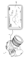
- FIG. 1 is a diagram conceptually showing an image pickup apparatus and an external recorder connected to the image pickup apparatus.
- FIG. 2 is a block diagram showing the main functions of the image pickup apparatus and the external recorder.
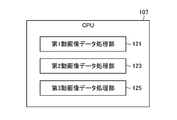
- FIG. 3 is a block diagram showing a function of processing moving image data realized by a CPU.
- FIG. 4 is a schematic diagram showing an example of the third moving image data.
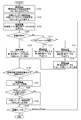
- FIG. 5 is a flow chart illustrating an imaging method.
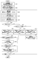
- FIG. 6 is a flow chart illustrating an imaging method.
- FIG. 7 is a schematic diagram showing an example of the third moving image data.
- FIG. 8 is a schematic diagram showing an example of the third moving image data.
- FIG. 9 is a schematic diagram showing an example of the third moving image data.
- FIG. 10 is a flow chart illustrating an imaging method.
- FIG. 11 is a diagram showing a comparison result displayed on the rear monitor of the image pickup apparatus.
- FIG. 12 is a block diagram showing the functions of the image pickup apparatus and the external recorder.
- FIG. 1 is a diagram conceptually showing an image pickup device and an external recorder connected to the image pickup device.
- the image pickup device (digital camera) 1 is connected to the external recorder 3 with an HDMI (registered trademark) (High-Definition Multimedia Interface (high-definition multimedia interface)) cable 5.
- the image pickup apparatus 1 captures moving images (moving image data) and still images in response to a command from an operation unit such as a shutter button. Further, in the shooting preparation state, the live view image, which is the display data, is displayed on the rear monitor (not shown) provided on the back surface of the image pickup device 1 and / or on the view finder (not shown) of the image pickup device 1.
- the image pickup apparatus 1 has an HDMI output terminal which is an example of the connection portion 109 (FIG. 2), and is connected to the external recorder 3 via the HDMI cable 5.
- the image pickup device 1 outputs the captured moving image data to the external recorder 3 via the HDMI cable 5.
- the external recorder 3 is an example of an external device that can be connected to the image pickup device 1.
- the external recorder 3 has an HDMI input terminal which is an example of the connection unit 203 (FIG. 2), and is connected to the image pickup apparatus 1 by an HDMI cable 5.
- the external recorder 3 acquires the moving image data captured by the image pickup device 1 via the HDMI cable 5 and records it in the recording unit 209. Further, the external recorder 3 acquires the moving image data captured by the image pickup device 1 via the HDMI cable 5 and displays it on the display unit 207.
- the connection between the image pickup apparatus 1 and the external recorder 3 has been described as an example in which the HDMI cable 5 is used, but the connection is not limited to this example.
- the image pickup apparatus 1 and the external recorder 3 may be connected by a USB (Universal Serial Bus) cable, or may be connected by a radio such as Wi-Fi as described later.
- USB Universal Serial Bus
- BT. 709 and BT. There are many types and settings for processing moving image data.
- BT. 709 and BT. There are 2100, or Log video and video RAW that are independently specified by each camera manufacturer. Therefore, in order to display the moving image data captured by the image pickup device 1 on the display unit (monitor) 207 of the external recorder 3 with the correct color and brightness, the external recorder is set according to the moving image quality setting of the image pickup device 1. It is necessary to change the monitor image quality setting of 3.
- the "moving image quality setting" and the “monitor image quality setting" are at least one of a color gamut, a gamma, a video range, a LookUpTable, and a brightness setting.
- the video image quality setting of the image pickup device 1 and the monitor image quality setting of the external recorder 3 may not match.
- the moving image quality setting of the image pickup device 1 is set to BT. While it is 2100, the monitor image quality setting of the external recorder 3 is BT. It may be 709. In this case, BT. 2100 and BT.
- the processing in the gamma and the color gamut is significantly different from that of the 709. Therefore, BT.
- the live view image displayed on the external recorder 3 processed by the 709 is BT.
- the exposure is darker and the saturation is lower than the moving image data of the image pickup apparatus 1 processed by the 2100.
- the user looks at the live view image displayed on the display unit 207 of the external recorder 3 and changes the moving image quality setting of the image pickup device 1 to take an image. Specifically, the image is taken with the moving image quality setting with increased saturation or increased exposure. Then, BT. In the image pickup apparatus 1 in which the moving image data is generated by the setting of 2100, the moving image data is too saturated or too exposed.
- the user needs to confirm whether or not the image quality setting of the display unit 207 of the external recorder 3 is correctly set with respect to the moving image quality setting of the image pickup device 1. Therefore, in the present embodiment, it is possible to easily visually determine whether or not the monitor image quality setting of the display unit 207 of the external recorder 3 is correctly set with respect to the moving image quality setting of the image pickup device 1. do.
- FIG. 2 is a block diagram showing the main functions of the image pickup apparatus 1 and the external recorder 3.
- the image pickup device 1 mainly includes a lens 103, an image pickup element 105, a CPU (Central Processing Unit) (processor) 107, a display unit 113, a memory 111, and a connection unit 109.
- the external recorder 3 mainly includes a connection unit 203, a CPU 205, a display unit 207, and a recording unit 209.
- the lens 103 forms a subject image (optical image) on the image pickup device 105.
- the lens 103 has a control mechanism such as an aperture, and the image pickup device 1 has a shutter or the like for controlling the image formation of a subject image on the image pickup element 105.
- the image pickup element 105 includes a light receiving surface in which a large number of light receiving elements are arranged in a matrix. The light corresponding to the subject image formed on the light receiving surface of the image pickup element 105 is received by each light receiving element and converted into an electric signal. R (red), G (green), and B (blue) color filters are provided on the light receiving surface of the image sensor 105, and a color image of the subject can be acquired based on the signals of each color.
- various image pickup devices such as CMOS (Complementary Metal-Oxide Semiconductor) and CCD (Charge-Coupled Device) can be used.
- CMOS Complementary Metal-Oxide Semiconductor
- CCD Charge-Coupled Device
- the image sensor 105 performs noise removal, amplification, and the like of the analog image signal via the internal AFE (Analog Front End) (not shown), and also performs internal A / D converter (Analog / Digital conversion). It is converted into a digital image signal with a gradation width via an instrument) (not shown).
- the AFE and the A / D converter may be externally connected.
- the moving image data captured by the image pickup apparatus 1 is composed of data composed of a plurality of frames, and each frame is generated as a digital image signal as described above.
- the digital image signal (a signal composed of frames constituting the moving image data) is image-processed by the CPU 107.
- the CPU 107 performs image processing such as color signal separation, white balance adjustment, and gamma correction on the digital image signal.
- the CPU 107 performs each image processing on the digital image signal according to the type and setting of the moving image described above. The image processing performed by the CPU 107 will be described later.
- the CPU 107 performs general control of the other image pickup apparatus 1.
- the CPU 107 reads necessary programs and information used for various controls from the memory 111, and performs various processes and various controls.
- the memory 111 is an internal memory of the image pickup apparatus 1, and stores various programs necessary for imaging of the image pickup apparatus 1.
- the CPU 107 controls the display of the display unit 113. Specific examples of the display unit 113 are a rear monitor and an electronic viewfinder of the image pickup apparatus 1.
- connection portion 109 of the image pickup apparatus 1 and the connection portion 203 of the external recorder 3 are connected by an HDMI cable 5.
- Moving image data is input from the image pickup apparatus 1 to the connection portion 203 of the external recorder 3.
- the external recorder 3 records the input moving image data in the recording unit 209.
- the CPU 205 displays the input moving image data on the display unit 207.
- the display unit 207 is connected from the connection unit via the CPU 205, but the display unit 207 and the connection unit 203 may be connected, for example, the CPU 205 may control the display unit.
- the CPU 205 performs general control including recording control to the recording unit 209 described above for the external recorder 3.
- the CPU 205 reads necessary programs and information used for various controls from the memory (not shown) of the external recorder 3 and performs various processes and various controls performed by the CPU 205.
- Programmable processors include CPUs, which are general-purpose processors that execute software (programs) and act as various functional units, and programmable processors whose circuit configurations can be changed after manufacturing, such as FPGAs (Field Programmable Gate Arrays). It includes a dedicated electric circuit which is a processor having a circuit configuration specially designed for executing a specific process such as a logic device (Programmable Logic Device: PLD) and an ASIC (Application Specific Integrated Circuit).
- PLD Programmable Logic Device
- ASIC Application Specific Integrated Circuit
- One functional unit may be composed of one of these various processors, or may be composed of two or more processors of the same type or different types (for example, a plurality of FPGAs or a combination of a CPU and an FPGA). You may. Further, a plurality of functional units may be configured by one processor. As an example of configuring a plurality of functional units with one processor, first, one processor is configured by a combination of one or more CPUs and software, as represented by a computer used for a client or a server. , There is a form in which this processor acts as a plurality of functional parts.
- SoC System On Chip
- FIG. 3 is a block diagram showing a function of processing moving image data realized by the CPU 107.
- the CPU 107 includes a first moving image data processing unit 121, a second moving image data processing unit 123, and a third moving image data processing unit 125.
- the first moving image data processing unit 121 processes the moving image data (RAW) based on the moving image image quality setting (first setting condition).
- the moving image data (RAW) is moving image data that has not been image-processed yet, and is data that has the information of the subject image that captures the image pickup element 105 as it is.
- the moving image quality setting is a condition set in the image pickup apparatus 1, and the first moving image data processed by the moving image quality setting is used as the recorded moving image data or the live view image.
- the video image quality setting is set to BT. 2100 HLG (HybridLogGamma) and PQ (Perceptual Quantization).
- the second moving image data processing unit 123 processes the moving image data (RAW) based on the monitor image quality setting (second setting condition).
- the monitor image quality setting is a condition set in the external recorder 3, and the display unit 207 of the external recorder 3 displays the second moving image data processed by the monitor image quality setting.
- the monitor image quality setting of the display unit 207 of the external recorder 3 is set to BT.
- the second moving image data processing unit 123 has a BT.
- the moving image data (RAW) is processed based on 709.
- the third moving image data processing unit 125 generates the third moving image data indicating the difference between the moving image image quality setting and the monitor image quality setting based on the first moving image data and the second moving image data. By looking at the third moving image data, the user can visually easily determine the difference between the moving image quality setting and the monitor image quality setting.
- the first moving image data and the second moving image data have different image quality. Therefore, the user can easily visually discriminate the different image quality by looking at the third moving image data displayed on the display unit 207.
- the moving image quality setting of the image pickup apparatus 1 and the monitor image quality setting of the display unit 207 of the external recorder 3 match, the first moving image data and the second moving image data have the same image quality. Become. Therefore, the user can easily visually determine the same image quality by looking at the third moving image data displayed on the display unit 207.
- FIG. 4 is a schematic diagram showing an example of the third moving image data.
- the third moving image data V3 (1) alternately alternates a plurality of first frame VF1s constituting the first moving image data V1 and a plurality of second frames VF2 constituting the second moving image data V2 in chronological order. Generated side by side.
- the first frame VF1 and the second frame VF2 are arranged every 5 frames in chronological order.
- the first frame VF1 is processed by the moving image quality setting
- the second frame VF2 is processed by the monitor image quality setting.
- the image quality of the first frame VF1 and the second frame VF2 is different.
- the third moving image data V3 (1) is displayed on the display unit 207
- the first frame VF1 and the second frame VF2 having different image quality are repeatedly displayed at predetermined intervals. Therefore, since the image quality of the displayed third moving image data V3 (1) changes repeatedly, the user can easily visually determine that the moving image image quality setting and the monitor image quality setting are different.
- the moving image image quality setting and the monitor image quality setting are the same, the image quality of the first frame VF1 and the second frame VF2 is the same. Therefore, since the image quality of the third moving image data V3 (1) is stably displayed without being changed, the user can easily visually determine that the video image quality setting and the monitor image quality setting are the same. be able to.
- the third moving image data V3 (1) a plurality of first frame VF1 and a plurality of second frame VF2 are alternately arranged along a time series as shown in the figure.
- the first moving image data a plurality of first frame VF1
- the second moving image data a plurality of second frame VF2
- the third moving image data V3 (1) may be configured by alternately arranging the first frame VF1 and the second frame VF2 for each single frame.
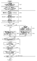
- FIG. 5 is a flow chart illustrating an image pickup method (and a program for executing the image pickup method) using the image pickup apparatus 1 to which the external recorder 3 is connected.
- the first moving image data processing unit 121 of the image pickup device 1 acquires the moving image quality setting "MV_SET” of the image pickup device 1 (step S101).
- the monitor image quality setting "MON_SET” of the external recorder 3 is transmitted from the external recorder 3 (CPU 205) to the image pickup device 1 via the HDMI cable 5, and the second moving image data processing unit 123 of the image pickup device 1 monitors. Acquire the image quality setting "MON_SET" (step S102).
- the CPU 107 acquires moving image data (RAW) from the image sensor 105 (step S103). Specifically, the frames constituting the moving image data (RAW) are acquired in the order of frame numbers in chronological order. After that, the CPU 107 receives the signal of the recording start instruction and determines whether or not the moving image is being recorded (step S104). When the CPU 107 determines that the moving image is being recorded, the first moving image data processing unit 121 of the imaging device 1 generates the first moving image data corresponding to "MV_SET", and the first moving image data is used as an external recorder. Send to 3 (step S105). On the other hand, when the CPU 107 determines that the moving image recording has not been performed, the third moving image data processing unit 125 determines whether or not the number calculated by the following equation is an even number (step S111).
- Int (Flame / n) Int (Flame / n)
- Int ( ⁇ ) in the formula means that the decimal number of the number ⁇ in parentheses is truncated
- Flame means the frame number of the moving image data (RAW)
- n means the frame period of processing switching.
- the frame period n for processing switching can be arbitrarily determined by the user.
- the first moving image data processing unit 121 when the CPU 107 determines that the number calculated by the equation is an even number, the first moving image data processing unit 121 generates the first moving image data corresponding to "MV_SET" and the third moving image data. It is sent to the processing unit 125 (step S112).
- the second moving image data processing unit 123 when the CPU 107 determines that the number calculated by the equation is not an even number, the second moving image data processing unit 123 generates the second moving image data corresponding to "MON_SET", and the third moving image data. It is sent to the processing unit 125 (step S113).
- the third moving image data processing unit 125 generates the third moving image data from the generated first moving image data and the second moving image data, and sends the third moving image data to the external recorder 3 (the third moving image data).
- Step S114 the first moving image data and the second moving image data are switched and generated according to the number of Frame (frame number) / n (frame cycle of processing switching), and then the third moving image data is generated. Generate moving image data. As a result, it is possible to efficiently perform the process of generating the first moving image data and the process of generating the second moving image data for the moving image data (RAW).
- RAW moving image data
- the CPU 107 determines whether or not the moving image quality setting of the image pickup apparatus 1 has been updated (step S106). Then, when the moving image quality setting of the image pickup apparatus 1 is updated, the CPU 107 updates the “MV_SET” of the image pickup apparatus 1 (step S107).
- the CPU 107 determines whether or not the monitor image quality setting of the external recorder 3 has been updated (step S108). After that, the updated "MON_SET" is transmitted from the external recorder 3 to the image pickup apparatus 1 (step S109). After that, the CPU 107 determines whether or not the moving image mode has ended (step S110), and if the moving image mode has not ended, the process returns to step S103 for the next frame of the moving image data (RAW). Will be done.
- the third moving image data processing unit 125 generates third moving image data in which a plurality of first frame VF1s and a plurality of second frame VF2s are alternately arranged. .. Then, the user can easily visually determine whether or not the moving image quality setting and the monitor image quality setting are correctly set by looking at the third moving image data displayed on the display unit 207 of the external recorder 3. be able to.
- each of the above configurations and functions can be appropriately realized by any hardware, software, or a combination of both.
- the CPU 107 may perform the moving image data processing instead of each moving image data processing unit.
- a computer-readable recording medium non-temporary recording medium that records such a program, or a computer on which such a program can be installed.
- the first moving image data or the second moving image data is generated for the frame constituting the moving image data (RAW) according to the frame number (steps S111 to step 5 in FIG. 5). See S113).
- both the first moving image data and the second moving image data are generated for the frames constituting the moving image data (RAW).
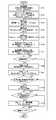
- FIG. 6 is a flow chart illustrating an image pickup method (and a program for executing the image pickup method) using the image pickup apparatus 1 to which the external recorder 3 is connected.
- the first moving image data processing unit 121 of the image pickup device 1 acquires the moving image quality setting "MV_SET” of the image pickup device 1 (step S201).
- the monitor image quality setting "MON_SET” of the external recorder 3 is transmitted from the external recorder 3 (CPU 205) to the image pickup device 1 via the HDMI cable 5, and the second moving image data processing unit 123 of the image pickup device 1 monitors. Acquire the image quality setting "MON_SET" (step S202).
- the CPU 107 acquires moving image data (RAW) from the image sensor 105 (step S203). After that, the first moving image data processing unit 121 generates the first moving image data of "MV_SET” (step S204). Further, the second moving image data processing unit 123 generates the second moving image data of "MON_SET" (step S205).
- RAW moving image data
- the CPU 107 receives the signal of the recording start instruction and determines whether or not the moving image is being recorded (step S206).
- the first moving image data processing unit 121 generates the first moving image data corresponding to "MV_SET" and sends it to the external recorder 3 (step S207).
- the third moving image data processing unit 125 determines whether or not the number calculated by the above equation (see step S111 in FIG. 5) is an even number. A determination is made (step S213).
- the first moving image data processing unit 121 of the image pickup apparatus 1 transfers the first moving image data corresponding to "MV_SET" to the third moving image. It is sent to the image data processing unit 125 (step S214).
- the second moving image data processing unit 123 of the image pickup apparatus 1 uses the second moving image data corresponding to "MON_SET" as the third moving image. It is sent to the data processing unit 125 (step S215).
- the third moving image data processing unit 125 generates the third moving image data from the generated first moving image data and the second moving image data, and sends the third moving image data to the external recorder 3 (step S216).
- both the first moving image data and the second moving image data are generated for the frames constituting the moving image data (RAW).
- the first moving image data and the second moving image data are provided for all the frames constituting the moving image data (RAW).
- the plurality of first frame VF1s constituting the first moving image data V1 and the plurality of second frame VF2s are alternately arranged by the third moving image data processing unit 125.
- the third moving image data is generated.
- the user can correctly set the video image quality setting of the image pickup device 1 and the monitor image quality setting of the display unit 207 of the external recorder 3. It can be easily visually determined whether or not it is present.
- the first frame VF1 and the second frame VF2 are combined to generate the third moving image data (third frame VF3). That is, in the present embodiment, by synthesizing the first frame and the second frame, the third moving image data showing the difference between the moving image quality setting and the monitor image quality setting is generated.
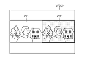
- FIG. 7 is a schematic diagram showing an example of the third moving image data of the present embodiment.
- the third frame VF3 (2) constituting the third moving image data shown in FIG. 7 includes a first frame VF1 constituting the first moving image data and a second frame VF2 constituting the second moving image data.
- the first frame VF1 is arranged on the left side and the second frame VF2 is arranged side by side on the right side to synthesize the third frame VF3 (2).
- FIG. 8 is a schematic diagram showing an example of the third moving image data of the present embodiment.
- the third frame VF3 (3) constituting the third moving image data shown in FIG. 8 includes a first frame VF1 constituting the first moving image data and a second frame VF2 constituting the second moving image data.
- the second frame VF2 is superimposed and displayed on a part of the region of the first frame VF1 to form the third frame VF3 (3).
- the user can easily visually determine the difference between the moving image quality setting and the monitor image quality setting. ..
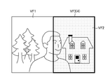
- FIG. 9 is a schematic diagram showing an example of the third moving image data of the present embodiment.
- the third frame VF3 (4) constituting the third moving image data shown in FIG. 9 is a part of the first frame VF1 constituting the first moving image data and the second frame constituting the second moving image data. Combine with a part of frame VF2.
- the image of the left half of the first frame VF1 and the image of the right half of the second frame VF2 are arranged side by side on the left side to form the third frame VF3 (4).
- the user can easily visually discriminate the difference between the video image quality setting and the monitor image quality setting. can do.
- FIG. 10 is a flow chart illustrating the imaging method (and the program for executing the imaging method) of the present embodiment.
- the first moving image data processing unit 121 of the image pickup device 1 acquires the moving image quality setting "MV_SET” of the image pickup device 1 (step S301).
- the monitor image quality setting "MON_SET” of the external recorder 3 is transmitted from the external recorder 3 (CPU 205) to the image pickup device 1 via the HDMI cable 5, and the second moving image data processing unit 123 of the image pickup device 1 monitors. Acquire the image quality setting "MON_SET" (step S302).
- the CPU 107 acquires moving image data (RAW) from the image sensor 105 (step S303). Then, the first moving image data processing unit 121 generates the first moving image data corresponding to "MV_SET” (step S304). Further, the second moving image data processing unit 123 generates the second moving image data corresponding to "MON_SET" (step S305).
- RAW moving image data
- the CPU 107 determines whether or not the video recording is being performed by receiving the signal of the recording start instruction (step S306).
- the first moving image data processing unit 121 sends the first moving image data to the external recorder 3 (step S307).
- the third moving image data processing unit 125 generates the third moving image data by synthesizing the first moving image data and the second moving image data (step S313). ). After that, the third moving image data is transmitted from the image pickup apparatus 1 to the external recorder 3 (step S314).
- the third moving image data processing unit 125 generates the third moving image data in which the first frame VF1 and the second frame VF2 are combined. Then, the user correctly sets the moving image quality setting of the image pickup apparatus 1 and the monitor image quality setting of the display unit 207 of the external recorder 3 by checking the third moving image data displayed on the display unit 207 of the external recorder 3. It can be easily visually determined whether or not it is made.
- the CPU 107 displays the comparison result between the moving image quality setting and the monitor image quality setting on the display unit (rear monitor or electronic viewfinder) 113 of the image pickup device 1.
- FIG. 11 is a diagram showing a comparison result displayed on the rear monitor of the image pickup apparatus 1.
- the CPU 107 displays the comparison result 7 between the moving image quality setting and the monitor image quality setting on the rear monitor.
- the moving image mode is "BT.2100” and the video range is “Limited” in the moving image quality setting of the image pickup apparatus 1.
- the monitor image quality setting of the external recorder 3 the moving image mode is "BT.709” and the video range is “Limited”. If the video image quality setting of the image pickup device 1 and the monitor image quality setting of the external recorder 3 match, " ⁇ " (or "OK") is displayed, and if they do not match, "x” is displayed. "(Or” NG ”) is attached. In this way, by indicating whether or not the setting conditions are met, that is, by indicating the difference in the setting conditions, the user can easily determine which setting of the external recorder 3 should be changed to match the moving image quality setting of the image pickup apparatus 1. can do.
- the image pickup device 1 and the external recorder 3 are wirelessly connected.
- FIG. 12 is a block diagram showing the functions of the image pickup device 1 and the external recorder 3 of this example.
- the parts already described in FIG. 2 are designated by the same reference numerals and the description thereof will be omitted.
- the image pickup device 1 and the external recorder 3 are wirelessly connected.
- the connection unit 109 has a communication unit (antenna) 110A, is wirelessly connected to the communication unit (antenna) 110B, and transmits the imaged moving image data to the external recorder 3. .
- Specific examples of wireless connection include Wi-Fi, UWB (Ultra Wide Band), wireless HDMI, and wireless SDI (Serial Digital Interface) connection.
- the image pickup device 1 controls the image so that the exposure and color can be confirmed as a live view image.
- this example is effective when there is no monitor image quality setting of the external recorder 3 that matches the moving image quality setting of the image pickup device 1.
- FIG. 13 is a flow chart illustrating the imaging method (and the program for executing the imaging method) of this example.
- the first moving image data processing unit 121 of the image pickup device 1 acquires the moving image quality setting "MV_SET” of the image pickup device 1 (step S401). After that, the monitor image quality setting "MON_SET” of the external recorder 3 is transmitted from the external recorder 3 to the image pickup device 1, and the second moving image data processing unit 123 of the image pickup device 1 acquires the monitor image quality setting "MON_SET” (step). S402).
- the image pickup device 1 acquires moving image data (RAW) from the image pickup element 105 (step S403).
- the first moving image data processing unit 121 generates the first moving image data by the first image processing corresponding to "MV_SET” (step S404).
- the second moving image data processing unit 123 generates the second moving image data by the second image processing corresponding to "MON_SET” (step S405).
- the first moving image data is transmitted from the image pickup apparatus 1 to the external recorder 3 (step S406).
- the second moving image data is transmitted from the image pickup apparatus 1 to the external recorder 3 (step S407).
- the CPU 107 determines whether or not the moving image is being recorded (step S408).
- the external recorder 3 records the first moving image data (step S409).
- the external recorder 3 displays the second moving image data on the display unit (monitor) 207 (step S410).
- the image pickup device 1 generates the first moving image data of the moving image quality setting and the second moving image data of the monitor image quality setting, and sends them to the external recorder 3. Then, the external recorder 3 records the first moving image data when recording a moving image, and displays the second moving image data on the display unit (monitor) 207. As a result, even if the monitor image quality setting of the external recorder 3 that matches the moving image quality setting of the image pickup apparatus 1 does not exist, the live view image whose exposure and color can be confirmed can be displayed on the display unit 207.
- Image pickup device 3 External recorder 5: HDMI cable 103: Lens 105: Image sensor 107: CPU 109: Connection unit 111: Memory 113: Display unit 121: First moving image data processing unit 123: Second moving image data processing unit 125: Third moving image data processing unit 203: Connection unit 205: CPU 207: Display unit 209: Recording unit
Landscapes
- Engineering & Computer Science (AREA)
- Multimedia (AREA)
- Theoretical Computer Science (AREA)
- Signal Processing (AREA)
- Computer Vision & Pattern Recognition (AREA)
- General Physics & Mathematics (AREA)
- Physics & Mathematics (AREA)
- Health & Medical Sciences (AREA)
- Evolutionary Computation (AREA)
- General Health & Medical Sciences (AREA)
- Medical Informatics (AREA)
- Software Systems (AREA)
- Databases & Information Systems (AREA)
- Computing Systems (AREA)
- Artificial Intelligence (AREA)
- Studio Devices (AREA)
- Television Signal Processing For Recording (AREA)
Priority Applications (5)
| Application Number | Priority Date | Filing Date | Title |
|---|---|---|---|
| JP2022533944A JP7352028B2 (ja) | 2020-06-30 | 2021-06-25 | 撮像装置、撮像方法、及びプログラム |
| CN202180045791.8A CN115769591B (zh) | 2020-06-30 | 2021-06-25 | 摄像装置、摄像方法及记录介质 |
| DE112021003484.7T DE112021003484T5 (de) | 2020-06-30 | 2021-06-25 | Bildgebungsvorrichtung, bildgebungsverfahren und programm |
| US18/064,572 US12316958B2 (en) | 2020-06-30 | 2022-12-12 | Imaging device, imaging method, and program |
| US19/197,147 US20250267358A1 (en) | 2020-06-30 | 2025-05-02 | Imaging device, imaging method, and program |
Applications Claiming Priority (2)
| Application Number | Priority Date | Filing Date | Title |
|---|---|---|---|
| JP2020-112549 | 2020-06-30 | ||
| JP2020112549 | 2020-06-30 |
Related Child Applications (1)
| Application Number | Title | Priority Date | Filing Date |
|---|---|---|---|
| US18/064,572 Continuation US12316958B2 (en) | 2020-06-30 | 2022-12-12 | Imaging device, imaging method, and program |
Publications (1)
| Publication Number | Publication Date |
|---|---|
| WO2022004570A1 true WO2022004570A1 (ja) | 2022-01-06 |
Family
ID=79316031
Family Applications (1)
| Application Number | Title | Priority Date | Filing Date |
|---|---|---|---|
| PCT/JP2021/024053 Ceased WO2022004570A1 (ja) | 2020-06-30 | 2021-06-25 | 撮像装置、撮像方法、及びプログラム |
Country Status (5)
| Country | Link |
|---|---|
| US (2) | US12316958B2 (cg-RX-API-DMAC7.html) |
| JP (1) | JP7352028B2 (cg-RX-API-DMAC7.html) |
| CN (1) | CN115769591B (cg-RX-API-DMAC7.html) |
| DE (1) | DE112021003484T5 (cg-RX-API-DMAC7.html) |
| WO (1) | WO2022004570A1 (cg-RX-API-DMAC7.html) |
Citations (3)
| Publication number | Priority date | Publication date | Assignee | Title |
|---|---|---|---|---|
| JP2010172462A (ja) * | 2009-01-29 | 2010-08-12 | Toshiba Corp | 医用画像表示装置 |
| JP2010183173A (ja) * | 2009-02-03 | 2010-08-19 | Fujifilm Corp | 撮像装置及びそのスルー画像表示方法 |
| JP2013229699A (ja) * | 2012-04-25 | 2013-11-07 | Sony Corp | 撮像装置、撮像処理方法、画像処理装置および撮像処理システム |
Family Cites Families (7)
| Publication number | Priority date | Publication date | Assignee | Title |
|---|---|---|---|---|
| JP2007043386A (ja) * | 2005-08-02 | 2007-02-15 | Olympus Corp | 電子撮像装置、電子撮像装置の制御方法及び画像処理装置 |
| US8379130B2 (en) * | 2009-08-07 | 2013-02-19 | Qualcomm Incorporated | Apparatus and method of processing images based on an adjusted value of an image processing parameter |
| JP5476150B2 (ja) * | 2010-02-10 | 2014-04-23 | 富士フイルム株式会社 | 画像処理装置、画像処理方法、画像処理プログラムおよび記録媒体 |
| JP6549409B2 (ja) * | 2015-05-13 | 2019-07-24 | オリンパス株式会社 | 撮像装置、撮像方法、およびプログラム |
| JP2018042198A (ja) | 2016-09-09 | 2018-03-15 | オリンパス株式会社 | 撮像装置及び撮像方法 |
| JP7046661B2 (ja) * | 2018-03-15 | 2022-04-04 | キヤノン株式会社 | 表示装置およびその制御方法、プログラム |
| JP7199158B2 (ja) | 2018-05-23 | 2023-01-05 | キヤノン株式会社 | 画像処理装置およびその制御方法ならびにプログラム |
-
2021
- 2021-06-25 CN CN202180045791.8A patent/CN115769591B/zh active Active
- 2021-06-25 DE DE112021003484.7T patent/DE112021003484T5/de active Pending
- 2021-06-25 WO PCT/JP2021/024053 patent/WO2022004570A1/ja not_active Ceased
- 2021-06-25 JP JP2022533944A patent/JP7352028B2/ja active Active
-
2022
- 2022-12-12 US US18/064,572 patent/US12316958B2/en active Active
-
2025
- 2025-05-02 US US19/197,147 patent/US20250267358A1/en active Pending
Patent Citations (3)
| Publication number | Priority date | Publication date | Assignee | Title |
|---|---|---|---|---|
| JP2010172462A (ja) * | 2009-01-29 | 2010-08-12 | Toshiba Corp | 医用画像表示装置 |
| JP2010183173A (ja) * | 2009-02-03 | 2010-08-19 | Fujifilm Corp | 撮像装置及びそのスルー画像表示方法 |
| JP2013229699A (ja) * | 2012-04-25 | 2013-11-07 | Sony Corp | 撮像装置、撮像処理方法、画像処理装置および撮像処理システム |
Also Published As
| Publication number | Publication date |
|---|---|
| CN115769591A (zh) | 2023-03-07 |
| JPWO2022004570A1 (cg-RX-API-DMAC7.html) | 2022-01-06 |
| JP7352028B2 (ja) | 2023-09-27 |
| CN115769591B (zh) | 2025-08-12 |
| US12316958B2 (en) | 2025-05-27 |
| US20250267358A1 (en) | 2025-08-21 |
| DE112021003484T5 (de) | 2023-04-27 |
| US20230114332A1 (en) | 2023-04-13 |
Similar Documents
| Publication | Publication Date | Title |
|---|---|---|
| JP6732726B2 (ja) | 撮像装置、撮像方法、およびプログラム | |
| JP2010093472A (ja) | 撮像装置および撮像装置用信号処理回路 | |
| TWI823956B (zh) | 在相機感測器模組和視覺處理系統之間交換經hdr 組合的串流和相關聯的曝光 | |
| EP3402179B1 (en) | Image-capturing system, image-capturing method, and program | |
| KR101753261B1 (ko) | 촬영 시스템 및 그 영상품질 동기화 방법 | |
| CN110225223B (zh) | 图像处理设备及其控制方法 | |
| JP2019140468A (ja) | 画像処理装置、及びその制御方法 | |
| US20050190270A1 (en) | Method and apparatus for processing image signal | |
| JP2009065519A (ja) | 画像処理装置 | |
| US9912873B2 (en) | Image pickup apparatus equipped with display section and method of controlling the same | |
| US10880491B2 (en) | Imaging apparatus including controller for converting dynamic range image data | |
| JP7352028B2 (ja) | 撮像装置、撮像方法、及びプログラム | |
| EP3672218B1 (en) | Imaging apparatus | |
| JP7803906B2 (ja) | 画像処理装置、撮像装置、画像処理方法、画像処理プログラム及び記録媒体 | |
| Mody et al. | High performance and flexible imaging Sub-system | |
| JP7790940B2 (ja) | 撮像装置及びそれを制御する制御方法およびプログラム、光学装置 | |
| CN101127920B (zh) | 数字成像装置的彩色处理参数设置 | |
| JP2009105687A (ja) | 撮像システム | |
| TWI869963B (zh) | 分時產生帶通影像的方法以及分時產生帶通影像的系統 | |
| JP2010279457A (ja) | 電子内視鏡、電子内視鏡システムおよび色調整方法 | |
| JP3038688B2 (ja) | 撮影装置 | |
| JP6875603B2 (ja) | 撮像装置、撮像方法、及びプログラム | |
| JP3755950B2 (ja) | 撮影装置 | |
| WO2019053764A1 (ja) | 撮像装置 | |
| WO2025115562A1 (ja) | 画像データ処理装置、画像データ処理方法、画像データ処理プログラム、撮像装置及び学習装置 |
Legal Events
| Date | Code | Title | Description |
|---|---|---|---|
| 121 | Ep: the epo has been informed by wipo that ep was designated in this application |
Ref document number: 21833703 Country of ref document: EP Kind code of ref document: A1 |
|
| ENP | Entry into the national phase |
Ref document number: 2022533944 Country of ref document: JP Kind code of ref document: A |
|
| 122 | Ep: pct application non-entry in european phase |
Ref document number: 21833703 Country of ref document: EP Kind code of ref document: A1 |
|
| WWG | Wipo information: grant in national office |
Ref document number: 202180045791.8 Country of ref document: CN |