WO2022004497A1 - 吸収性物品 - Google Patents
吸収性物品 Download PDFInfo
- Publication number
- WO2022004497A1 WO2022004497A1 PCT/JP2021/023657 JP2021023657W WO2022004497A1 WO 2022004497 A1 WO2022004497 A1 WO 2022004497A1 JP 2021023657 W JP2021023657 W JP 2021023657W WO 2022004497 A1 WO2022004497 A1 WO 2022004497A1
- Authority
- WO
- WIPO (PCT)
- Prior art keywords
- width direction
- sheet
- absorbent article
- pair
- surface sheet
- Prior art date
- Legal status (The legal status is an assumption and is not a legal conclusion. Google has not performed a legal analysis and makes no representation as to the accuracy of the status listed.)
- Ceased
Links
Images
Classifications
-
- A—HUMAN NECESSITIES
- A61—MEDICAL OR VETERINARY SCIENCE; HYGIENE
- A61F—FILTERS IMPLANTABLE INTO BLOOD VESSELS; PROSTHESES; DEVICES PROVIDING PATENCY TO, OR PREVENTING COLLAPSING OF, TUBULAR STRUCTURES OF THE BODY, e.g. STENTS; ORTHOPAEDIC, NURSING OR CONTRACEPTIVE DEVICES; FOMENTATION; TREATMENT OR PROTECTION OF EYES OR EARS; BANDAGES, DRESSINGS OR ABSORBENT PADS; FIRST-AID KITS
- A61F13/00—Bandages or dressings; Absorbent pads
- A61F13/15—Absorbent pads, e.g. sanitary towels, swabs or tampons for external or internal application to the body; Supporting or fastening means therefor; Tampon applicators
- A61F13/45—Absorbent pads, e.g. sanitary towels, swabs or tampons for external or internal application to the body; Supporting or fastening means therefor; Tampon applicators characterised by the shape
- A61F13/47—Sanitary towels, incontinence pads or napkins
- A61F13/475—Sanitary towels, incontinence pads or napkins characterised by edge leakage prevention means
-
- A—HUMAN NECESSITIES
- A61—MEDICAL OR VETERINARY SCIENCE; HYGIENE
- A61F—FILTERS IMPLANTABLE INTO BLOOD VESSELS; PROSTHESES; DEVICES PROVIDING PATENCY TO, OR PREVENTING COLLAPSING OF, TUBULAR STRUCTURES OF THE BODY, e.g. STENTS; ORTHOPAEDIC, NURSING OR CONTRACEPTIVE DEVICES; FOMENTATION; TREATMENT OR PROTECTION OF EYES OR EARS; BANDAGES, DRESSINGS OR ABSORBENT PADS; FIRST-AID KITS
- A61F13/00—Bandages or dressings; Absorbent pads
- A61F13/15—Absorbent pads, e.g. sanitary towels, swabs or tampons for external or internal application to the body; Supporting or fastening means therefor; Tampon applicators
- A61F13/45—Absorbent pads, e.g. sanitary towels, swabs or tampons for external or internal application to the body; Supporting or fastening means therefor; Tampon applicators characterised by the shape
- A61F13/49—Absorbent pads, e.g. sanitary towels, swabs or tampons for external or internal application to the body; Supporting or fastening means therefor; Tampon applicators characterised by the shape specially adapted to be worn around the waist, e.g. diapers or nappies
- A61F13/494—Absorbent pads, e.g. sanitary towels, swabs or tampons for external or internal application to the body; Supporting or fastening means therefor; Tampon applicators characterised by the shape specially adapted to be worn around the waist, e.g. diapers or nappies characterised by edge leakage prevention means
-
- A—HUMAN NECESSITIES
- A61—MEDICAL OR VETERINARY SCIENCE; HYGIENE
- A61F—FILTERS IMPLANTABLE INTO BLOOD VESSELS; PROSTHESES; DEVICES PROVIDING PATENCY TO, OR PREVENTING COLLAPSING OF, TUBULAR STRUCTURES OF THE BODY, e.g. STENTS; ORTHOPAEDIC, NURSING OR CONTRACEPTIVE DEVICES; FOMENTATION; TREATMENT OR PROTECTION OF EYES OR EARS; BANDAGES, DRESSINGS OR ABSORBENT PADS; FIRST-AID KITS
- A61F13/00—Bandages or dressings; Absorbent pads
- A61F13/15—Absorbent pads, e.g. sanitary towels, swabs or tampons for external or internal application to the body; Supporting or fastening means therefor; Tampon applicators
- A61F13/51—Absorbent pads, e.g. sanitary towels, swabs or tampons for external or internal application to the body; Supporting or fastening means therefor; Tampon applicators characterised by the outer layers of the pads
-
- A—HUMAN NECESSITIES
- A61—MEDICAL OR VETERINARY SCIENCE; HYGIENE
- A61F—FILTERS IMPLANTABLE INTO BLOOD VESSELS; PROSTHESES; DEVICES PROVIDING PATENCY TO, OR PREVENTING COLLAPSING OF, TUBULAR STRUCTURES OF THE BODY, e.g. STENTS; ORTHOPAEDIC, NURSING OR CONTRACEPTIVE DEVICES; FOMENTATION; TREATMENT OR PROTECTION OF EYES OR EARS; BANDAGES, DRESSINGS OR ABSORBENT PADS; FIRST-AID KITS
- A61F13/00—Bandages or dressings; Absorbent pads
- A61F13/15—Absorbent pads, e.g. sanitary towels, swabs or tampons for external or internal application to the body; Supporting or fastening means therefor; Tampon applicators
- A61F13/53—Absorbent pads, e.g. sanitary towels, swabs or tampons for external or internal application to the body; Supporting or fastening means therefor; Tampon applicators characterised by the absorbing medium
- A61F13/531—Absorbent pads, e.g. sanitary towels, swabs or tampons for external or internal application to the body; Supporting or fastening means therefor; Tampon applicators characterised by the absorbing medium having a homogeneous composition through the thickness of the pad
- A61F13/532—Absorbent pads, e.g. sanitary towels, swabs or tampons for external or internal application to the body; Supporting or fastening means therefor; Tampon applicators characterised by the absorbing medium having a homogeneous composition through the thickness of the pad inhomogeneous in the plane of the pad
- A61F13/533—Absorbent pads, e.g. sanitary towels, swabs or tampons for external or internal application to the body; Supporting or fastening means therefor; Tampon applicators characterised by the absorbing medium having a homogeneous composition through the thickness of the pad inhomogeneous in the plane of the pad having discontinuous areas of compression
Definitions
- the present invention relates to an absorbent article.
- Patent Document 1 discloses an absorbent article capable of enhancing the retention of body fluid.
- This absorbent article is provided with a liquid permeable upper layer sheet on the skin contact surface side of the surface sheet.
- the upper sheet is arranged along the longitudinal direction in the central portion in the width direction, and has a central region including an excretion opening contact region.
- the absorbent article has an upper layer pressing portion in which the surface sheet and the upper layer sheet are compressed in the thickness direction, and an absorbent body pressing portion in which the surface sheet and the absorber are compressed in the thickness direction.
- the absorber squeezing portion has a longitudinal squeezing portion formed along the longitudinal direction on the lateral side in the width direction from the upper layer sheet.
- both ends in the width direction of the upper layer sheet are not joined to the surface sheet, and the thickness of both ends in the width direction of the upper layer sheet is equal to or greater than the thickness of the central portion thereof. thin. Therefore, the widthwise ends of the upper layer sheet have a smaller amount of body fluid that can be retained in the voids between the constituent fibers of the upper layer sheet than the central portion thereof. As a result, when the amount of body fluid is large when the absorbent article is used, the body fluid diffused from the center to the end of the upper layer sheet overflows from the end without accumulating in the upper layer sheet in the width direction. There is a risk.
- the widthwise length of the upper sheet is smaller than the longitudinal length, so that the bodily fluid diffuses to the widthwise ends of the bodily fluid before it is sufficiently diffused to both sides in the longitudinal direction. There is a risk that the body fluid will proceed and leak outward from the end in the width direction. Further, since the upper layer sheet having high water retention is located closer to the skin than the surface sheet, if the upper layer sheet holding the body fluid comes into contact with the excretion port, the skin feel may not be good.
- An object of the present invention is to provide an absorbent article capable of suppressing leakage from the widthwise end portion of body fluid, that is, lateral leakage, and improving the feel even when the amount of body fluid is large.
- the absorbent articles of the present invention are as follows.
- An absorbent article having a longitudinal direction, a width direction, and a thickness direction comprising a surface sheet, an absorber, and an auxiliary sheet located between the surface sheet and the absorber.
- the length of the auxiliary sheet is larger than the length of the surface sheet, and each of both ends of the auxiliary sheet extends to the outside of each of the both end edges of the surface sheet, and the surface thereof.
- the sheet comprises a central region located in the central portion of the width direction and a pair of end regions located at both ends of the width direction and adjacent to both outer sides of the central region in the width direction.
- An absorbent article in which the thickness-wise length of each of the pair of end regions is greater than the thickness-wise length of the central region.
- an absorbent article capable of improving the feel while suppressing leakage from the widthwise end portion of the body fluid, that is, lateral leakage, even when the amount of the body fluid is large.
- An absorbent article having a longitudinal direction, a width direction, and a thickness direction, comprising a surface sheet, an absorber, and an auxiliary sheet located between the surface sheet and the absorber, wherein the absorbent article includes the width direction.
- the length of the auxiliary sheet is larger than the length of the surface sheet, and each of both ends of the auxiliary sheet extends to the outside of each of the both end edges of the surface sheet, and the surface sheet is a surface sheet.
- the pair of ends including a central region located in the central portion of the width direction and a pair of end regions located at both ends of the width direction and adjacent to both outer sides of the central region in the width direction.
- An absorbent article in which the length in the thickness direction in each of the partial regions is larger than the length in the thickness direction in the central region.
- the surface sheet is formed so that the thickness in each of the pair of end regions is larger than the thickness in the central region in the width direction. That is, in the surface sheet, the thickness of both ends in the width direction is larger than the thickness of the central portion. Therefore, both ends of the surface sheet in the width direction have a larger amount of body fluid that can be held in the voids between the constituent fibers of the surface sheet than the central portion thereof, and like a bank protruding toward the skin side. Can function. As a result, even when the amount of body fluid (eg, menstrual blood) is large when the absorbent article is used, the body fluid diffused from the center to the end of the surface sheet through the inside or the surface of the surface sheet is spread on the surface.
- body fluid eg, menstrual blood
- the fiber densities at both ends of the surface sheet in the width direction are relatively low, a soft feel can be imparted.
- this absorbent article even when the amount of body fluid is large, lateral leakage of body fluid can be further suppressed and the touch can be further improved.
- the body fluid that has reached the end can stay at the end and is difficult to move in the width direction, so that other body fluid can easily move from the center to the lower part in the thickness direction, that is, to the absorber.
- this absorbent article even when the amount of body fluid is large, the movement of the body fluid in the width direction can be restricted, and lateral leakage can be further suppressed.
- the surface sheet, the auxiliary sheet, and the absorber are formed by squeezing, and further include a pair of squeezed portions extending along the longitudinal direction and arranged at intervals in the width direction, and the pair of end regions.
- the absorbent article according to any one of aspects 1 to 3, wherein the outer edge in the width direction in each of the above is located outside in the width direction in each of the pair of compression portions. In this absorbent article, the widthwise outer edges of each of the pair of end regions are located outside of each of the pair of compression sections.
- both ends of the surface sheet in the width direction can function as a bank protruding toward the skin side, whereby the body fluid diffused from the center to the end of the surface sheet is discharged to the end of the surface sheet. It can be easily accumulated in the water and can be prevented from leaking to the outside of the end.
- the widthwise length of the absorber is smaller than the widthwise length of the surface sheet, and in plan view, each of the pair of end regions is on both outer sides of the absorber in the width direction.
- the length of the absorber is smaller than the length of the surface sheet in the width direction, and the pair of end regions are located on both outer sides of the absorber in a plan view. Therefore, when the absorbent article is used, when the absorbent article is sandwiched between both thighs and an inward force in the width direction is applied to the absorber, a pair of non-joined ends located on the outer portion of the absorber. The part area tends to rise toward the skin side.
- both ends of the surface sheet in the width direction can be relatively erected on the skin side. Thereby, the amount of body fluid toward the end in the width direction of the surface sheet can be reduced. Therefore, in this absorbent article, lateral leakage of body fluid can be further suppressed even when the amount of body fluid is large.
- Aspect 5 further comprises a pair of end squeezed portions formed to squeeze the surface sheet, the auxiliary sheet and the absorber so as to straddle the outer edge in the width direction in the pair of end regions.
- the absorbent article comprises a pair of end squeezing portions formed to straddle the lateral outer edges of each of the pair of end regions. That is, the end squeezed portion is formed so as to straddle the outer edge in the width direction of the surface sheet. Therefore, when the body fluid diffused from the central part of the surface sheet reaches the end portion when the absorbent article is used, a part of the body fluid is absorbed below the surface sheet and the auxiliary sheet through the end pressing portion. You can pull it into your body.
- Aspect 8 The aspect according to any one of aspects 1 to 7, further comprising a pair of auxiliary squeezing portions formed by squeezing only the auxiliary sheet on the outside of the pair of end regions in the width direction in a plan view.
- the absorbent article further comprises a pair of auxiliary squeezing portions that squeeze only the auxiliary sheet outside the pair of end regions in the width direction. That is, in the width direction, the auxiliary pressing portion is formed on the auxiliary sheet outside the outer edge of the surface sheet. Therefore, even if the body fluid diffused from the central portion of the surface sheet leaks outward from the end portion when the absorbent article is used, the body fluid is drawn into the absorbent body below the auxiliary sheet via the auxiliary pressing portion. be able to. Therefore, in this absorbent article, lateral leakage of body fluid can be further suppressed even when the amount of body fluid is large.
- the position of the end portion in the width direction of the absorber is substantially the same as the position of the portion outside the surface sheet. Therefore, by confirming the color of the absorber that is visually recognized in the portion outside the surface sheet, it is possible to confirm whether or not the body fluid has been absorbed up to the end portion in the width direction of the absorber. As a result, the body fluid was absorbed up to the widthwise end of the absorber, and even though it was time to replace the absorbent article, it was not noticed, so the body fluid could not be completely absorbed by the absorber and leaked sideways. You can avoid the situation that you have done it.
- a pair of side sheets joined to both ends of the auxiliary sheet in the width direction and extending along the longitudinal direction are further provided, and between the center portion in the width direction and both ends in the width direction in a plan view.
- This absorbent article has low rigidity between the central portion in the width direction (surface sheet, auxiliary sheet and absorber) and both ends in the width direction (side sheet, auxiliary sheet and absorber) in a plan view. It has a pair of low-rigidity portions (auxiliary sheet and absorber).
- the absorbent article when the absorbent article is used, the absorbent article can be easily deformed into a substantially W shape when viewed from the longitudinal direction, starting from the pair of low-rigidity portions. That is, both ends in the width direction of the absorbent article can be relatively upright on the skin side. Thereby, the amount of body fluid toward the end in the width direction of the surface sheet can be reduced. Therefore, in this absorbent article, lateral leakage of body fluid can be further suppressed even when the amount of body fluid is large.
- absorbent article according to the embodiment will be described using a sanitary napkin as an example.
- the types and uses of the absorbent articles of the present invention are not limited to the examples thereof, and can be applied to other absorbent articles as long as they do not deviate from the scope of the subject matter of the present invention.
- Other absorbent articles include, for example, panty liners, light incontinence pads, disposable diapers.
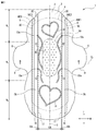
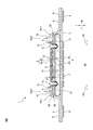
- FIG. 1 to 2 are views showing a configuration example of the absorbent article 1 according to the embodiment.
- FIG. 1 is a plan view showing a state in which the absorbent article 1 is unfolded
- FIG. 2 is a cross-sectional view taken along the line II-II of FIG.
- the absorbent article 1 has a longitudinal direction L, a width direction W, and a thickness direction T orthogonal to each other.
- the upper side and the lower side of the figure are the front side and the rear side in the longitudinal direction L, respectively, and the left side and the right side are the left side and the right side in the width direction W, respectively, and the front side with respect to the paper surface.
- the back side are the upper side and the lower side in the thickness direction T, respectively.
- the absorbent article 1 has a longitudinal center line C L (virtual line) that passes through the center of the width direction W and extends in the longitudinal direction L, and a width direction center line C W (virtual line) that passes through the center of the longitudinal direction L and extends in the width direction W. Line) and.
- Longitudinal center line C L-going direction and sides were respectively inward and inside in the width direction W, the outward and outer away orientation and a side each width direction W.
- the direction and the side toward the center line C W in the width direction are the inward and the inside of the longitudinal direction L, respectively, and the direction and the side away from it are the outward and the outside of the longitudinal direction L, respectively.
- the view of the absorbent article 1 placed on the plane including the longitudinal direction L and the width direction W from the upper side in the thickness direction T is referred to as a plan view, and the shape grasped in the plan view is referred to as a planar shape.
- Any direction in the plane including the longitudinal direction L and the width direction W is referred to as a plane direction.
- the wearer wears the absorbent article 1 the sides relatively close to and far from the skin surface of the wearer in the thickness direction T are referred to as the skin side and the non-skin side, respectively. These definitions are also commonly used for each material of the absorbent article 1.
- the absorbent article 1 (excluding the wing portion) has a substantially rectangular shape long in the longitudinal direction L and short in the width direction W in a plan view, and both ends of the longitudinal direction L have a substantially semicircular shape.
- the shape of the absorbent article 1 is not particularly limited as long as it is long in the longitudinal direction L and short in the width direction W, and examples thereof include a rounded rectangle, an ellipse, a gourd shape, and an hourglass shape.
- the absorbent article 1 includes a pair of wing portions 9 extending from a portion having a substantially rectangular shape to both outer sides in the width direction W.
- the wing portion 9 has a substantially trapezoidal shape.
- the shape may be, for example, a semicircular shape or a semi-elliptical shape.
- the absorbent article 1 includes a front surface sheet 2, an auxiliary sheet 5, and an absorber 4, and in the present embodiment, further includes a back surface sheet 3 and a clothing fixing portion 7.
- the surface sheet 2 is a liquid-permeable sheet, and in the present embodiment, constitutes the surface of the absorbent article 1 on the skin side.
- the auxiliary sheet 5 is a liquid permeable sheet, and in this embodiment, it is laminated on the non-skin side of the surface sheet 2.
- the absorber 4 is a liquid-absorbing and liquid-retaining material, and is located between the front surface sheet 2 (and the auxiliary sheet 5) and the back surface sheet 3.
- the back surface sheet 3 is a liquid-impermeable sheet, and in the present embodiment, constitutes the surface of the absorbent article 1 on the non-skin side.
- the clothing fixing portion 7 is an adhesive that adheres the absorbent article 1 to the skin side surface of the underwear, and is located on the non-skin side surface of the back sheet 3 in the present embodiment. Therefore, in the absorbent article 1, the front surface sheet 2, the auxiliary sheet 5, the absorber 4, the back surface sheet 3, and the clothing fixing portion 7 are laminated in this order in the thickness direction T.
- the absorbent article 1 may further include an exterior sheet on the non-skin side of the back sheet 3.
- the absorbent article 1 further includes a pair of side seats 6 and a pair of clothing fixing portions 8.
- the pair of side sheets 6 are hydrophilic or water-repellent sheets, and in the present embodiment, they are located on both sides of the auxiliary sheet 5 in the width direction W.
- the pair of side seats 6 includes a pair of leak-proof walls 16 extending along the longitudinal direction L inside the width direction W.
- Each of the pair of leak-proof walls 16 (FA) has a fixed end 16E1 at the outer end in the width direction W and is joined to the auxiliary sheet 5, and an inner end is a free end 16E2 and is not joined to the member. do not do.
- the leak-proof wall 16 may have an elastic member extending along the longitudinal direction L at the free end 16E2.
- the edge 2E of the surface sheet 2 in the width direction W is separated from the fixed end 16E1 and the free end 16E2 of the leak-proof wall 16 facing the width direction W, and therefore, in a plan view, the surface sheet.
- the auxiliary sheet 5 is exposed between the 2 and the pair of leak-proof walls 16.
- the pair of clothing fixing portions 8 is an adhesive that adheres the pair of wing portions 9 to the non-skin side surface of the underwear, and is located on the non-skin side surface of the back sheet 3 in the pair of wing portions 9 in the present embodiment.
- the surface sheet 2 has a substantially rectangular shape that is long in the longitudinal direction L and short in the width direction W, and both ends of the longitudinal direction L have a substantially semicircular shape.
- the surface sheet 2 includes a first fiber layer 2a containing water-retaining fibers and a second fiber layer 2b containing water-retaining fibers and hydrophobic fibers.
- the skin-side surface of the first fiber layer 2a constitutes the skin-side surface of the surface sheet 2
- the non-skin-side surface is in contact with the skin-side surface of the second fiber layer 2b.
- the non-skin side surface of the second fiber layer 2b constitutes the non-skin side surface of the surface sheet 2.
- the surface sheet 2 may be any one of the first fiber layer 2a and the second fiber layer 2b, or may be a three layer further including another fiber layer. Further, the types of constituent fibers of the first fiber layer 2a and the second fiber layer 2b are not limited to the above examples as long as the surface sheet 2 becomes a liquid permeable sheet.
- the auxiliary sheet 5 has a substantially rectangular shape that is long in the longitudinal direction L and short in the width direction W, and has a substantially semicircular shape at both ends of the longitudinal direction L.
- the auxiliary sheet 5 has a shape slightly larger in the width direction W than the surface sheet 2. Therefore, the length (width) of the auxiliary sheet 5 in the width direction W is larger than the length (width) of the surface sheet 2 in the width direction W. Then, in a plan view, each of both ends of the auxiliary sheet 5 in the width direction W extends to the outside of each of both end edges 2E of the surface sheet 2 in the width direction W.
- each of the both end edges 5E of the auxiliary sheet 5 in the width direction W is located outside the end edges 2E of the surface sheet 2 in the width direction W.
- the length (width) of the auxiliary sheet 5 in the width direction W is substantially the same as the length (width) of the absorber 4 in the width direction W.
- the surface sheet 2 and the auxiliary sheet 5 are bonded to each other with an adhesive (not shown, eg, hot melt adhesive).
- the adhesive extends along the longitudinal direction L and is applied to the surface sheet 2 or the auxiliary sheet 5 in a plurality of predetermined patterns arranged in the width direction W (not shown). Examples of the predetermined pattern include a stripe shape, an omega repeating shape, a wave repeating shape, and the like.
- the adhesive is applied to a region that is substantially axisymmetric with respect to the longitudinal centerline C L.
- the surface sheet 2 includes a central region CA located at the center of the width direction W, and a pair of end regions EA located at both ends of the width direction W and adjacent to both outer sides of the center region CA in the width direction W. Contains (partitioned).
- the range of the pair of end regions EA in the surface sheet 2 in the width direction W is the remainder excluding the central region CA.
- each of the central region CA and the pair of end regions EA is separated by each of a pair of virtual borders 17 extending along the longitudinal direction L.
- the central region CA is a region to which the adhesive is applied in the above-mentioned predetermined pattern, and the pair of end regions EA is coated with the adhesive adjacent to both outer sides of the central region CA in the width direction W. It is an area that has not been done. That is, the central region CA is a region joined to the auxiliary sheet 5, and the pair of end regions EA is a region not joined to the auxiliary sheet 5. Therefore, each of the pair of boundary lines 17 indicates the outer edge of the region where the adhesive is present in the width direction W.
- each of the pair of end region EA is formed as a fixed end by connecting the inner edge in the width direction W to the edge of the central region CA, and the outer edge in the width direction W (longitudinal direction L). (Except for both ends) is a free end that is not joined to any member. That is, each of the pair of end regions EA has a configuration in which a gap V can be generated between the free end and the auxiliary sheet 5 because the free end easily moves with respect to the auxiliary sheet 5 in the thickness direction T. It is a configuration that can stand up from the sheet 5.
- the end region EA may be partially joined to the auxiliary sheet 5 or the side sheet 6.
- the central region CA is the region where the first fiber layer 2a and the second fiber layer 2b are joined to each other
- the pair of end regions EA is the region where the first fiber layer 2a and the second fiber layer 2b are not joined to each other. Area may be.
- each of the pair of end regions EA has a configuration in which the first fiber layer 2a and the second fiber layer 2b are relatively easy to move with each other and can stand up more from the auxiliary sheet 5.
- the first fiber layer 2a and the second fiber layer 2b may be joined to each other.
- the central region CA and a pair of end regions EA are symmetric with respect to both the longitudinal centerline C L.
- the range of the central region CA in the surface sheet 2 may be, for example, a range of 80 to 96% of the length of the surface sheet 2. If it is less than 80%, the length of the end region EA in the width direction W becomes long, and there is a possibility that the end region EA will be rolled up. In that case, the wearer tends to feel a sense of discomfort in the rolled-up part. Further, a gap is formed between the surface sheet 2 in the vicinity of the rolled-up portion and the wearer's skin surface, and the body fluid easily leaks along the wearer's skin surface. If it exceeds 96%, the end region EA tends to be in close contact with the auxiliary sheet 5 due to the joining between the central region CA and the auxiliary sheet 5, and it becomes difficult to move and stand up from the auxiliary sheet 5.
- each of the pair of end region EA has a larger amount of body fluid that can be held in the voids between the constituent fibers of the surface sheet 2 than the central region CA, and in the thickness direction T toward the skin side. It can function like a protruding bank.
- the central region CA is pressed against the auxiliary sheet 5 and joined in a state where the adhesive is applied and diffused in the thickness direction T. Therefore, the thickness of the central region CA is relatively thin as compared with that before joining.
- each of the pair of end regions EA is arranged on the auxiliary sheet 5 in a state where the adhesive is not applied. Therefore, the thickness of the end region EA is almost the same as before joining. Thereby, the length (thickness) d2 of the end region EA in the thickness direction T can be made larger than the length (thickness) d1 of the central region CA in the thickness direction T.
- the central region CA is formed by one layer of the sheet member of the surface sheet 2, and in each of the pair of end regions EA, the sheet member of the surface sheet 2 is thickened inward in the width direction W. It is formed by folding back to the skin side or the non-skin side in the direction T.
- the length (thickness) d1 of the central region CA in the thickness direction T becomes the thickness of one layer of the sheet member of the surface sheet 2, and the length of each of the pair of end regions EA in the thickness direction T (thickness).
- Thickness) d2 is the thickness of two layers of the sheet member of the surface sheet 2, and d1 ⁇ d2. It was
- the thickness of the central region CA is compared with that before joining. And it is relatively thin.
- the thickness of the end region EA is , Almost the same as before joining. Therefore, in these cases, the length (thickness) d2 of the end region EA in the thickness direction T can be made larger than the length (thickness) d1 of the central region CA in the thickness direction T.
- the method of making the length d2 of the end region EA in the thickness direction T larger than the length d1 of the central region CA in the thickness direction T is not limited to the above example.
- another non-woven fabric sheet is arranged between each of the pair of end region EA and the auxiliary sheet 5, or the first fiber layer 2a and the second fiber layer in the pair of end region EA. Examples thereof include a method of arranging another non-woven fabric sheet between the 2b and the 2b.
- the surface sheet 2 is formed so that the thickness in each of the pair of end region EA is larger than the thickness in the central region CA in the width direction W. That is, in the surface sheet 2, the thickness of both ends (end region EA) in the width direction W is larger than the thickness of the central portion (central region CA). Therefore, at both ends of the surface sheet 2 in the width direction W, the amount of body fluid that can be held in the voids between the constituent fibers of the surface sheet 2 is larger than that at the center thereof, and the embankment that protrudes toward the skin side. Can function like.
- the surface sheet 2 is formed so that each of the pair of end region EA is non-bonded to the auxiliary sheet 5. That is, in the surface sheet 2, both ends (end region EA) in the width direction W are not joined to the auxiliary sheet 5. Therefore, it is possible to make it difficult for the body fluid diffused from the central portion (central region CA) of the surface sheet 2 to the end portion to be transferred to the auxiliary sheet 5 located outside the width direction W from the end portion. Further, the amount of body fluid that can be held in the voids between the constituent fibers can be relatively increased at both ends of the surface sheet 2 in the width direction W.
- both ends of the surface sheet 2 in the width direction W are not joined to other materials and have a high degree of freedom, it is possible to improve the followability to the skin surface at both ends.
- the present absorbent article 1 even when the amount of the body fluid is large, the lateral leakage of the body fluid can be further suppressed and the touch can be further improved.
- the fiber density in each of the pair of end region EA is lower than the fiber density in the central region CA. Therefore, the body fluid diffused in the width direction W from the central region CA to the end region EA can be made difficult to diffuse before the end region EA.
- the end region EA and the central region CA are the same end and center of the surface sheet 2, and the length (thickness) d2 of the end region EA is the length of the central region CA ( Thickness) larger than d1. Therefore, the fiber density of the end region EA can be lower than the fiber density of the central region CA.
- the fiber density at both ends (end region EA) in the width direction W is lower than the fiber density at the central portion (central region CA). Therefore, even if a large amount of body fluid flows through the inside of the surface sheet 2 in the width direction W by a capillary phenomenon, the fiber density at the end portion is relatively low, so that the body fluid can be difficult to spread to the end portion. Further, since the fiber densities at both ends of the surface sheet 2 in the width direction W are relatively low, elasticity can be given to both ends, and thus a soft feel can be imparted. As described above, in the present absorbent article 1, even when the amount of the body fluid is large, the lateral leakage of the body fluid can be further suppressed and the touch can be further improved.
- the fiber density on the skin side in each of the pair of end region EA is higher than the fiber density on the non-skin side. Therefore, it is possible to make it difficult for the body fluid diffused from the central region CA to the end region EA to move to the non-skin surface side of the end region EA.
- the fiber density of the first fiber layer 2a on the skin side of the first fiber layer 2a and the second fiber layer 2b constituting the surface sheet 2 is set to the fiber density of the second fiber layer 2b on the non-skin side. Is higher than. Therefore, the fiber density on the skin side of the edge region EA can be made higher than the fiber density on the non-skin side.
- the fiber density on the side in contact with the net becomes higher than the fiber density on the side not in contact with the net when the fiber is deposited on the strip-shaped net to manufacture the surface sheet 2.
- the surface of the surface sheet 2 on the skin side can be made into a surface in contact with the net.
- the fiber density on the skin side of both ends (end region EA) in the width direction W is higher than the fiber density on the non-skin side. Therefore, in the width direction W, it is possible to make it difficult for the body fluid diffused from the central portion (central region CA) of the surface sheet 2 to the end portion to move to the non-skin surface side of the end portion, and the thickness direction of the end portion. It is possible to make it difficult to move to the surface of the auxiliary sheet 5 located below the T.
- the body fluid that has reached the end stays at the end and is difficult to move in the width direction W, so that other body fluids can easily move from the center to the lower side in the thickness direction T, that is, to the absorber 4. can.
- the present absorbent article 1 even when the amount of the body fluid is large, the transfer of the body fluid in the width direction W can be restricted, and the lateral leakage can be further suppressed.
- the mass density of the surface sheet 2 is lower than the mass density of the auxiliary sheet 5. Therefore, when using the absorbent article, most of the body fluid excreted in the central region CA is transferred from the low mass density surface sheet 2 to the high mass density auxiliary sheet before being transferred to the end region EA in the width direction W. It is possible to easily shift to the thickness direction T toward 5. As a result, the amount of body fluid that migrates toward the end portion (end region region EA) in the width direction W of the surface sheet 2 can be reduced. Therefore, in the present absorbent article 1, lateral leakage of body fluid can be further suppressed even when the amount of body fluid is large.
- the absorber 4 has a substantially rectangular shape that is long in the longitudinal direction L in a plan view, and has a substantially semicircular shape at both ends of the longitudinal direction L.
- the absorber 4 includes an absorbent core 4a and a core wrap 4b covering it.
- the length (width) of the absorber 4 in the width direction W is larger than the length (width) of the surface sheet 2 in the width direction W. Therefore, in a plan view, each of the pair of end regions EA is located inside the edges of the absorber 4 in the width direction W. As a result, even if the body fluid leaks laterally from each of the pair of end region EA in the width direction W, it can be absorbed by the absorber 4, so that the final lateral leakage can be suppressed.
- the portion of the auxiliary sheet 5 and the pair of side sheets 6 facing the absorber 4 on the non-skin side and the surface of the absorber 4 on the skin side have a predetermined pattern of an adhesive (example: hot melt adhesive). ).
- the portion of the auxiliary sheet 5, the pair of side sheets 6 and the absorber 4 facing the back surface sheet 3 on the non-skin side is bonded to the back surface sheet 3 with an adhesive of a predetermined pattern (example: hot melt adhesive) or a heat seal. Will be done.
- the excretion opening contact area XA is set in the center of the longitudinal direction L and slightly forward and in the center of the width direction W in a plan view.
- the excretion port contact area XA is an area that faces or contacts the user's excretion port when the absorbent article 1 is used.
- the excretion port contact area XA is appropriately set according to the type and use of the absorbent article.
- the excretion opening contact area XA is, for example, slightly forward in the center of the absorber 4 in the longitudinal direction L, about 1/10 to 1/2 of the total length of the absorber 4, and is absorbed in the width direction W. It is set in the substantially center of the body 4 with a width of about 1/3 to 1/2 of the total width of the absorber 4.
- the absorbent article 1 has a longitudinal anterior region A F , a longitudinal central region A C, and a longitudinal posterior region A B in the longitudinal direction L.
- the longitudinal central region AC includes the excretion opening contact region XA.
- the longitudinal anterior region A F is adjacent to the anterior portion of the longitudinal central region A C in the longitudinal direction L and includes the anterior end of the excretory opening contact area XA in the longitudinal direction L.
- the longitudinal posterior region A B is adjacent to the posterior portion of the longitudinal central region A C in the longitudinal direction L and includes the posterior end of the excretory opening contact region XA in the longitudinal direction L.
- the absorbent article 1 has a plurality of holes in at least the excretion opening contact area XA of the central region CA.
- the plurality of holes include a plurality of dot-shaped (circular) squeezed portions 15 formed by squeezing the surface sheet 2, the auxiliary sheet 5, and the absorber 4 in the thickness direction T.
- the hole portion is not limited to this example, and is intentionally formed when another configuration, for example, a hole (through hole) penetrating from the surface sheet 2 to the absorber 4, or the surface sheet 2 is formed by entanglement of fibers. Holes (void holes) due to fiber unevenness generated in the above can be mentioned.
- the shape of the squeezed portion 15 in a plan view is a circle, but other shapes such as a polygon, an ellipse, a star, and a line may be used.
- the absorbent article 1 further includes a pair of squeezing portions (squeezing grooves) 12, a pair of squeezing portions (squeezing grooves) 13, and squeezing portions (squeezing grooves) 11 and 14.
- the pair of squeezed portions 12 are arranged at intervals on both outer portions of the excretion opening contact area XA in the width direction W in a plan view, and extend continuously or intermittently along the longitudinal direction L.
- the pair of squeezed portions 13 are arranged in a plan view at the rear portion of the pair of squeezed portions 12 in the longitudinal direction L at intervals in the width direction W, and extend continuously or intermittently along the longitudinal direction L. There is.
- the squeezed portions 11 and 14 are located in front of and behind the excretion opening contact area XA in the longitudinal direction L, respectively, in a plan view.
- the squeezed portions 11 to 14 are formed by compressing the surface sheet 2, the auxiliary sheet 5, and the absorber 4 (the core wrap 4b on the skin side and the absorbent core 4a) in the thickness direction T.
- the bottom of the squeezed portions 11-14 in the thickness direction T is located within the absorbent core 4a, but may reach the core wrap 4b on the non-skin side.
- the shape of the squeezed portions 11 to 14 in a plan view is linear, but other shapes such as polygons, circles, ellipses, stars, characters, or character strings may be used. Further, at least one of the pressing portions 11 to 14 may be omitted.
- the outer edge of the width direction W in each of the pair of end regions EA is each of the pair of squeezed portions 12 or a pair of squeezed portions. It is located outside the width direction W in each of the portions 13. However, the compressed portion 12a located at the end of the compressed portion 12 in the longitudinal direction L and the compressed portion 13a located at the end of the compressed portion 13 in the longitudinal direction L are excluded. As a result, when the absorbent article 1 is used, the portion outside the width direction W of the pair of squeezed portions 12 (excluding the compressed portion 12a) in the absorbent article 1 is on the skin side with the pair of squeezed portions 12 as the starting point.
- the portion of the pair of end regions EA outside the pair of squeezed portions 12 in the width direction W of the surface sheet 2 can also be deformed toward the skin side.
- both ends of the surface sheet 2 in the width direction W can function like a bank protruding toward the skin side.
- the body fluid diffused from the central portion (central region CA) of the surface sheet 2 to the end portion can be easily collected at the end portion of the surface sheet 2, and leaks to the outside of the end portion. It can be suppressed from being put out.
- the compressed portion 12a located at the end of the squeezed portion 12 and the compressed portion 13a located at the end of the squeezed portion 13 are the outer edges of the width direction W in the end region EA. (That is, it is formed so as to straddle the outer edge 2E of the surface sheet 2). Therefore, it can be said that the pair of compressed portions 12a of the pair of squeezed portions 12 and the pair of compressed portions 13a of the pair of squeezed portions 13 are a pair of end squeezed portions.
- the compressed portion 12a and the compressed portion 13a quickly draw a part of the body fluid into the lower absorber 4. Can be done.
- the compressed portion 12a and the compressed portion 13a are not limited to the end portions of the squeezed portion 12 and the squeezed portion 13, and may be located in the middle of the squeezed portion 12 and the squeezed portion 13, from the squeezed portion 12 and the squeezed portion 13. It may be separated.
- the length of the compressed portion 12a and the compressed portion 13a in the extending direction is preferably 1 to 20% of the length of the compressed portion 12 or the compressed portion 13 in the extending direction, and is preferably 2 to 10%. If the length of the compressed portion 12a or the compressed portion 13a is short, the following effects are unlikely to occur, and if the length is long, the original effect of the end region EA is difficult to occur.
- the absorbent article 1 when the absorbent article 1 is used, a part of the body fluid that has reached the end portion (end region region EA) of the surface sheet 2 in the width direction W is compressed into the compressed portion 12a and the compressed portion 13a. Can be pulled into the lower absorber 4 via. Thereby, in the width direction W, the body fluid at the end portion of the surface sheet 2 and the body fluid migrating from the end portion to the outside can be suppressed from migrating to the outside from the end portion. Therefore, in the present absorbent article 1, lateral leakage of body fluid can be further suppressed even when the amount of body fluid is large.
- the color of the absorber 4 is viewed through the outer portion of the edge 2E of the surface sheet 2 in the width direction W in the plan view than through the central portion of the surface sheet 2. It is easy to check (including the color of the absorber when it absorbs body fluid). Thereby, by confirming the color of the absorber 4 visually recognized in the portion outside the surface sheet 2, it is possible to confirm whether or not the body fluid has been absorbed up to the end portion of the absorber 4 in the width direction W.
- the portion outside the surface sheet 2 has only the auxiliary sheet 5 in the thickness direction T.
- the surface sheet 2 and the auxiliary sheet 5 are present in the thickness direction T. Therefore, since the thickness of the portion outside the edge 2E of the surface sheet 2 can be made relatively thin, the color of the absorber 4 can be easily confirmed via the portion outside the edge 2E of the surface sheet 2.
- the color of the absorber 4 seen through the portion outside the surface sheet 2 (auxiliary sheet 5) in a plan view is the central portion of the surface sheet 2 (the surface sheet 2 and the auxiliary sheet 5). It is closer to the actual color of the absorber 4 than the color of the absorber seen through 5). Therefore, by confirming the color of the absorber 4 visually recognized in the portion outside the surface sheet 2, it is possible to confirm whether or not the body fluid has been absorbed up to the end portion of the absorber 4 in the width direction W.
- the body fluid is absorbed up to the end of the absorbent body 4 in the width direction W, and even though the timing of replacement of the absorbent article 1 has come, the body fluid is absorbed by the absorbent body 4 because it is not noticed. It is possible to avoid the situation where the side leaks without being cut.
- the core wrap 4b may be colored.
- the position of the edge of the absorber 4 can be clarified more, and the body fluid is absorbed by the absorber 4 because the absorption article 1 is not noticed even though the timing of replacement has come. It is possible to avoid the situation where the side leakage is not complete.
- the color difference between the surface sheet 2 and the core wrap 4b becomes easier to see, so that it can be used as a guide for the alignment of the width direction W and the longitudinal direction L at the time of mounting.
- the difference in color difference between the surface sheet 2 and the core wrap 4b may be 3 or more in ⁇ E.
- the absorbent article 1 has a pair of low-rigidity portions having low rigidity between the central portion in the width direction W and both end portions in the width direction W in a plan view.
- the central portion in the width direction W includes the surface sheet 2, the auxiliary sheet 5, and the absorber 4 laminated in the thickness direction T.
- both ends in the width direction include a side sheet 6, an auxiliary sheet 5, and an absorber 4 laminated in the thickness direction T.
- the portion between the central portion and both end portions in the width direction W includes the auxiliary sheet 5 and the absorber 4 laminated in the thickness direction T.
- the portion between the central portion and both end portions in the width direction W has few layers laminated in the thickness direction T and has low rigidity, that is, a pair of low rigidity portions. Therefore, when the absorbent article is used, the absorbent article can be easily deformed into a substantially W shape when viewed from the longitudinal direction, starting from the pair of low-rigidity portions.
- the pair of low-rigidity portions is easily deformed into a substantially W shape when viewed from the longitudinal direction. That is, both ends (end region EA) of the absorbent article 1 in the width direction W can be relatively upright on the skin side. Thereby, the amount of body fluid toward the end portion of the surface sheet 2 in the width direction W can be reduced. Therefore, in the present absorbent article 1, lateral leakage of body fluid can be further suppressed even when the amount of body fluid is large.
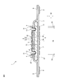
- FIG. 3 is a cross-sectional view showing another configuration example of the absorbent article 1 according to the embodiment. This figure is a cross-sectional view taken along line II-II in FIG.
- the pair of side seats 6 is not used, and the auxiliary seats 5 are further extended to both outer sides in the width direction W in place of the pair of side seats 6. Also in this case, the above-mentioned effects can be achieved.
- the absorber 4 is not limited to the above example.
- the length (width) of the absorber in the width direction W is smaller than the length (width) of the surface sheet 2 in the width direction W. You may.
- each of the pair of end regions EA will be located on both outer sides of the absorber in the width direction W.
- the absorbent article 1 is sandwiched between both thighs, and when a force toward the inside of the width direction W is applied to the absorber, the non-bonded article 1 is located on the outer portion of the absorber.
- the pair of end region EA tends to rise toward the skin side.
- both ends (end region EA) in the width direction W of the surface sheet 2 can be made relatively easy to stand on the skin side. Thereby, the amount of body fluid toward the end portion of the surface sheet 2 in the width direction W can be reduced. Therefore, even in such a case, even if the amount of the body fluid is large, the lateral leakage of the body fluid can be further suppressed.
- the squeezed part is not limited to the above example.
- the absorbent article 1 squeezes only the auxiliary sheet 5 outside the pair of end regions EA in the width direction W in plan view as another squeezing portion (squeezing groove).
- a pair of auxiliary squeezing portions may be further provided. That is, in a plan view, the auxiliary pressing portion may be formed on the auxiliary sheet 5 outside the outer edge 2E of the surface sheet 2 in the width direction W.
- each of the pair of auxiliary squeezing portions allows the bodily fluid diffused from the central region CA to leak outward from the end region EA when the absorbent article 1 is used. Can be pulled in quickly. Therefore, in the present absorbent article 1, lateral leakage of body fluid can be further suppressed even when the amount of body fluid is large.
- the first fiber layer 2a contains water-retaining fibers, whereby the surface sheet 2 can be made to feel good to the touch.
- the water-retaining fiber is not particularly limited as long as it is a fiber having a property of absorbing and retaining water (water-retaining). Examples of the water-retaining fiber include cellulosic fibers. In this embodiment, the water-retaining fiber is cotton.
- the second fiber layer 2b contains hydrophobic fibers and water-retaining fibers.
- the hydrophobic fiber is not particularly limited as long as it is a fiber having hydrophobicity. Examples of the hydrophobic fiber include thermoplastic resin fiber. In the present embodiment, the hydrophobic fiber is a PET / PE core-sheath type composite fiber.
- the water-retaining fibers are the same as the water-retaining fibers of the first fiber layer 2a.
- the auxiliary sheet 5 is not particularly limited as long as it is liquid permeable, and examples thereof include liquid permeable non-woven fabrics, for example, hydrophobic fiber non-woven fabrics, and thermoplastic resin fiber non-woven fabrics are particularly preferable. Used for. Further, when the surface sheet 2 contains water-retaining fibers such as cotton, the auxiliary sheet 5 may accordingly contain water-retaining fibers such as cotton. In the absorbent article 1 having such a structure, water-retaining fibers having high liquid diffusivity and the like communicate with each other from the first fiber layer 2a of the surface sheet 2 to the auxiliary sheet 5 via the second fiber layer 2b. Therefore, by utilizing the liquid diffusion of the body fluid by these fibers, the body fluid can be more stably transferred from the surface sheet 2 to the absorber 4 via the auxiliary sheet 5, while improving the feel of the surface sheet 2. , Absorption performance can be improved.
- the absorbent core 4a of the absorber 4 is not particularly limited as long as it has liquid absorbency and liquid retention, but for example, a liquid-retaining substance containing water-absorbent fibers such as pulp fibers. Water absorbing materials such as highly absorbent polymers (SAPs) can be mentioned.
- the core wrap 4b is not particularly limited as long as it can retain the form of the absorbent core 4a, and examples thereof include a liquid permeable sheet containing a hydrophilic non-woven fabric such as tissue.
- the side sheet 6 is not particularly limited, and examples thereof include a water-repellent treated nonwoven fabric and a breathable synthetic resin film.
- the back surface sheet 3 is not particularly limited, and examples thereof include a liquid-impermeable non-woven fabric, a synthetic resin film, and a composite sheet thereof.
- the wing portion 9 is formed of a side sheet 6 and a back surface sheet 3.
- the thickness of the seat member is measured by the following method.
- the sheet member is cut into a size of 10 mm ⁇ 10 mm and used as a sample.
- a magnified image of the cut surface parallel to the thickness direction T of the sample is taken from a direction perpendicular to the cut surface of the sheet member using a digital microscope (manufactured by KEYENCE Co., Ltd .: VHX-100). do.
- the enlarged image is an image enlarged to a magnification such that the entire thickness direction T of the sheet member can be photographed, and the magnification is, for example, 20 to 50 times.
- the thickness of the sheet member is measured.
- the thickness of one sheet member is measured at three separate cut surfaces, and the average value of the thicknesses measured from a total of 10 sheet members is taken as the sheet member thickness.
- the position of the cut surface on which the image is taken is as follows.
- Width direction W -For the non-joined portion of the end region (example: end region EA) (exemplified: the portion placed on the auxiliary sheet 5 without applying the adhesive), the non-joined portion is set to 3 mag in the width direction W.
- the position is the boundary between the 1st division and the 2nd division counting from the outside in the width direction W.
- the position is set to the central portion in the width direction W.
- the clothes fixing portion 7 is set at three positions, the front end, the center, and the rear end in the longitudinal direction L.
- the positions are set at three positions at the base of the wing portion 9 (two locations at both ends of the longitudinal direction L) and the center of the wing portion 9 in the longitudinal direction L.
- the product is divided into three parts in the longitudinal direction L, and the position is set at the center of the longitudinal direction L in each of the first region, the second region, and the third region.
- each seat member is divided into three in the longitudinal direction L and is set at the center position of each longitudinal direction L (three places in each seat member). ..
- an intermediate position between the embossing or the like that is, a place where the material is not compressed. Put it in the middle position.
- the position of the cut surface can be applied to the following measurement of fiber density.
- the fiber density of the sheet member is measured as follows.
- the sheet member is cut into a size of 10 mm ⁇ 10 mm and used as a sample.
- the cut surface parallel to the thickness direction T of the sample is magnified and observed using a scanning electron microscope (manufactured by JEOL Ltd .: JCM-5100).
- the enlarged image is an image magnified to a magnification such that a cross section of 30 to 60 fibers can be photographed, and the magnification is, for example, 150 to 500 times.
- the number of cross sections of the fibers is measured. That is, the number of cross sections of the cut fiber is counted on the cut surface of a predetermined area.
- the number of cross sections of the obtained fibers is converted into the number of cross sections of the fibers per 1 mm 2 , and this is used as the fiber density (lines / mm 2 ).
- the measurement is performed at three places, and the average value of the measured values is taken as the fiber density of the sample. That is, the density of the number of fibers is used as the fiber density.
- the number of fibers per unit area in the cross section parallel to the thickness direction T is used as the fiber density.
- the number of fibers per unit volume may be used as the fiber density.
- the number of fibers per unit volume can be obtained by, for example, analysis by X-ray CT. Although the numerical values differ between the fiber density per unit area and the fiber density per unit volume, they are the same in the relative comparison of the fiber densities between the fiber layers (example: comparison of large and small).
- the mass density of the sheet member is measured as follows. First, regarding the basis weight of the sheet, the sheet is cut into a size of 5 cm ⁇ 5 cm and used as a sample, and the mass is measured after the drying treatment in an atmosphere of 100 ° C. or higher. Divide the measured mass by the area of the sample to calculate the basis weight of the sample. The value obtained by averaging the basis weights of 10 samples is defined as the basis weight of the sheet. Next, regarding the thickness of the sheet, a thickness gauge equipped with a 15 cm 2 stylus (model FS-60DS manufactured by Daiei Kagaku Seiki Seisakusho Co., Ltd.) was used under the condition of a measured load of 3 g / cm 2. Measure the thickness of each sample.
- the thickness of three places is measured with one sample, and the average value of the thicknesses of the three places is taken as the thickness of each sample. Then, the mass density of the sheet is calculated by dividing the weighing of each sample of the sheet obtained by the above method by the thickness of each sample of the sheet obtained by the above method.
- the absorbent article of the present invention is not limited to each of the above-described embodiments, and can be appropriately combined or modified as long as it does not deviate from the object and purpose of the present invention.
Landscapes
- Health & Medical Sciences (AREA)
- Epidemiology (AREA)
- Engineering & Computer Science (AREA)
- Biomedical Technology (AREA)
- Heart & Thoracic Surgery (AREA)
- Vascular Medicine (AREA)
- Life Sciences & Earth Sciences (AREA)
- Animal Behavior & Ethology (AREA)
- General Health & Medical Sciences (AREA)
- Public Health (AREA)
- Veterinary Medicine (AREA)
- Absorbent Articles And Supports Therefor (AREA)
Abstract
Description
[態様1]
長手方向、幅方向及び厚さ方向を有し、表面シートと、吸収体と、前記表面シートと前記吸収体との間に位置する補助シートと、を備える吸収性物品であって、前記幅方向において、前記補助シートの長さは、前記表面シートの長さよりも大きく、前記補助シートの両端部の各々は、前記表面シートの両端縁の各々の外側に延出しており、前記表面シートは、前記幅方向の中央部に位置する中央領域と、前記幅方向の両端部に位置し、前記中央領域の前記幅方向の両外側に隣接する一対の端部領域と、を含み、前記一対の端部領域の各々における前記厚さ方向の長さは、前記中央領域の前記厚さ方向の長さよりも大きい、吸収性物品。
前記一対の端部領域の各々における繊維密度は前記中央領域における繊維密度よりも低い、態様1に記載の吸収性物品。
本吸収性物品では、表面シートは、一対の端部領域の各々における繊維密度が中央領域における繊維密度よりも低くなるように形成されている。すなわち、表面シートでは、幅方向における両端部の繊維密度は、中央部の繊維密度よりも低い。そのため、多量の体液が幅方向に表面シートの内部を毛細管現象で流れてきたとしても、端部の繊維密度が相対的に低いので、体液を端部に拡がり難くすることができる。また、表面シートの幅方向の両端部の繊維密度が相対的に低いため、柔らかな感触を付与できる。このように、本吸収性物品では、体液の量が多い場合でも体液の横漏れをより抑制できると共に、肌触りをより改善できる。
前記一対の端部領域の各々における肌側の繊維密度は、非肌側の繊維密度よりも高い、態様1又は2に記載の吸収性物品。
本吸収性物品では、表面シートは、一対の端部領域の各々における肌側の繊維密度が非肌側の繊維密度よりも高くなるように形成されている。すなわち、表面シートでは、幅方向における両端部の肌側の繊維密度は、非肌側の繊維密度よりも高い。そのため、表面シートの中央部から端部へ拡散した体液を、その端部の非肌面側へ移行し難くすることができ、端部の厚さ方向の下側に位置する補助シートの表面へ移行し難くできる。それにより、端部へ到達した体液が端部に留まり、幅方向へ移行し難くでき、よって、他の体液が中央部から厚さ方向の下方へ、すなわち、吸収体へ移行し易くできる。このように、本吸収性物品では、体液の量が多い場合でも体液の幅方向への移動を制限でき、横漏れをより抑制できる。
前記表面シート、前記補助シート及び前記吸収体を圧搾して形成され、前記長手方向に沿って延び、前記幅方向に間隔を空けて並んだ一対の圧搾部を更に備え、前記一対の端部領域の各々における前記幅方向の外側の端縁は、前記一対の圧縮部の各々における前記幅方向の外側に位置する、態様1乃至3のいずれか一項に記載の吸収性物品。
本吸収性物品では、一対の端部領域の各々における幅方向の外側の端縁は、一対の圧縮部の各々における幅方向の外側に位置している。それにより、吸収性物品の使用時に、吸収性物品における一対の圧縮部よりも外側の部分が、一対の圧縮部を起点として肌側に変形し、それに伴い表面シートにおける一対の圧縮部よりも外側の一対の端部領域の部分も同様に肌側に変形する。すなわち、表面シートにおける幅方向の両端部が肌側に変形する。そのため、表面シートにおける幅方向の両端部を肌側に向かって突出する堤のように機能させることができ、それにより、表面シートの中央部から端部へ拡散した体液を、表面シートの端部に溜まらせ易くでき、端部よりも外側に漏れ出すことを抑制できる。
前記一対の端部領域の各々は前記補助シートに非接合である、態様1乃至4のいずれか一項に記載の吸収性物品。
本吸収性物品では、表面シートは、一対の端部領域の各々が補助シートに非接合であるように形成されている。すなわち、表面シートでは、幅方向における両端部は補助シートに接合されていない。そのため、表面シートの中央部から端部へ拡散した体液を、その端部よりも幅方向の外側に位置する補助シートへ移行し難くすることができる。また、表面シートの幅方向の両端部が他の資材に接合されず自由度が高いため、両端部での肌面に対する追従性を高めることができる。このように、本吸収性物品では、体液の量が多い場合でも体液の横漏れをより抑制できると共に、肌触りをより改善できる。
前記吸収体の前記幅方向の長さは、前記表面シートの前記幅方向の長さよりも小さく、平面視で、前記一対の端部領域の各々は、前記吸収体の前記幅方向の両外側に位置する、態様5に記載の吸収性物品。
本吸収性物品は、幅方向において、吸収体の長さは表面シートの長さよりも小さく、平面視で、一対の端部領域は、吸収体の両外側に位置している。そのため、吸収性物品の使用時に、吸収性物品が両大腿に挟まれて、幅方向の内側に向かう力が吸収体に加わったとき、吸収体の外側の部分に位置する非接合の一対の端部領域は肌側に向かって立ち上がり易くなる。すなわち、表面シートにおける幅方向の両端部を相対的に肌側に起立させることができる。それにより、表面シートの幅方向の端部へ向かう体液の量を削減できる。よって、本吸収性物品では、体液の量が多い場合でも体液の横漏れをより抑制できる。
前記表面シート、前記補助シート及び前記吸収体を圧搾して、前記一対の端部領域における前記幅方向の外側の端縁を跨ぐように形成された一対の端部圧搾部を更に備える、態様5又は6に記載の吸収性物品。
本吸収性物品は、一対の端部領域の各々における幅方向の外側の端縁を跨ぐように形成された一対の端部圧搾部を備えている。すなわち、表面シートにおける幅方向の外側の端縁を跨ぐように端部圧搾部が形成されている。そのため、吸収性物品の使用時に、表面シートの中央部から拡散した体液が端部に到達したとき、その体液の一部を、端部圧搾部を介して、表面シート及び補助シートの下方の吸収体に引き込むことができる。それにより、表面シートにおける幅方向の端部の体液や端部から外側に移行しつつある体液がより外側に移行することを抑制できる。よって、本吸収性物品では、体液の量が多い場合でも体液の横漏れをより抑制できる。
平面視で、前記幅方向における前記一対の端部領域の外側に、前記補助シートのみを圧搾して形成された一対の補助圧搾部を更に備える、態様1乃至7のいずれか一項に記載の吸収性物品。
本吸収性物品は、幅方向において、一対の端部領域の外側に補助シートのみを圧搾する一対の補助圧搾部を更に備えている。すなわち、幅方向において、表面シートの外側の端縁よりも外側の補助シートに、補助圧搾部が形成されている。そのため、吸収性物品の使用時に、表面シートの中央部から拡散した体液が端部から外側に漏れ出したとしても、その体液を、補助圧搾部を介して、補助シートの下方の吸収体に引き込むことができる。よって、本吸収性物品では、体液の量が多い場合でも体液の横漏れをより抑制できる。
前記表面シートの質量密度は、前記補助シートの質量密度よりも低い、態様1乃至8のいずれか一項に記載の吸収性物品。
本吸収性物品では、表面シートの質量密度が補助シートの質量密度よりも低くなっている。そのため、吸収性物品の使用時に、体液の量が多い場合でも、質量密度の低い表面シートから質量密度の高い補助シートへ向かって厚さ方向に体液を容易に移行できる。それにより、表面シートにおける幅方向の端部へ向かって移行する体液の量を削減できる。よって、本吸収性物品では、体液の量が多い場合でも体液の横漏れをより抑制できる。
平面視で、前記幅方向において、前記表面シートの端縁より外側の部分を介して見る方が、前記表面シートの中央部を介して見るよりも、前記吸収体の色を確認し易い、態様1乃至9のいずれか一項に記載の吸収性物品。
本吸収性物品では、平面視で、表面シートの端縁より外側の部分を介して見る方が、表面シートの中央部を介して見るよりも吸収体の色(体液を吸収したときの吸収体の色を含む)を確認し易くなっている。すなわち、表面シートより外側の部分(補助シート)を介して見る吸収体の色は、表面シートの中央部(表面シートと補助シート)を介して見る吸収体の色よりも、実際の吸収体の色に近い。ここで、平面視で、吸収体の幅方向の端部の位置は、表面シートより外側の部分の位置と概ね同じである。したがって、表面シートより外側の部分で視認される吸収体の色を確認することで、吸収体の幅方向の端部まで体液を吸収したか否かを確認できる。それにより、吸収体の幅方向の端部まで体液を吸収して、吸収性物品の交換のタイミングが来たにもかかわらず、それに気づかなかったために、体液が吸収体に吸収しきらずに横漏れしてしまった、という事態を回避できる。
前記補助シートの前記幅方向の両端部に接合され、前記長手方向に沿って延びる一対のサイドシートを更に備え、平面視で、前記幅方向の中央部と、前記幅方向の両端部との間に、剛性の低い一対の低剛性部を有する、態様1乃至10のいずれか一項に記載の吸収性物品。
本吸収性物品は、平面視で、幅方向の中央部(表面シート、補助シート及び吸収体)と、幅方向の両端部(サイドシート、補助シート及び吸収体)との間に、剛性の低い一対の低剛性部(補助シート及び吸収体)を有している。そのため、吸収性物品の使用時に、一対の低剛性部を起点として、吸収性物品を長手方向から見て略W字型に変形させ易くできる。すなわち、吸収性物品における幅方向の両端部を相対的に肌側に起立させることができる。それにより、表面シートの幅方向の端部へ向かう体液の量を削減できる。よって、本吸収性物品では、体液の量が多い場合でも体液の横漏れをより抑制できる。
(1)X-Rite社製 X-Rite eXact Standerd(測定径:1.5mm)を準備する。
(2)試料の測定すべき部分のCIE L*a*b*座標を、位置を変えて10点以上測定し、それらの平均値([L1*,a1*,b1*])を算出する。
(3)サンプルの対比すべき部分のL*a*b*座標を、位置を変えて10点以上測定し、それらの平均値([L2*,a2*,b2*])を算出する。
(4)色差ΔEを、次の式:
ΔE={(L1*-L2*)2+(a1*-a2*)2+(b1*-b2*)2}0.5
により算出する。
(1)幅方向W
・端部領域(例示:端部領域EA)の非接合部(例示:接着剤を塗布されずに補助シート5上に載置された部分)については、非接合部を幅方向Wに3等分して3区分としたとき、幅方向Wの外側から数えて1区分目と2区分目の境界の位置にする。
・中央領域(例示:中央領域CA)については、幅方向Wの中央部の位置にする。
(2)長手方向L
・着衣固定部7の長手方向Lの前端、中心及び後端の3か所の位置にする。
なお、着衣固定部7がない製品においては、ウイング部9の根元(長手方向Lの両端の2か所)及びウイング部9の長手方向Lの中心の3か所の位置にする。着衣固定部7もウイング部9もない製品においては製品を長手方向Lに3分割した第1領域、第2領域及び第3領域の各々における長手方向Lの中心の位置にする。
シート部材が長手方向Lに間欠的に配置されるものについては、各シート部材を、長手方向Lに3分割し、それぞれの長手方向Lの中心の位置とする(各シート部材では3か所)。
ただし、上記の各位置において、エンボスやヒンジや圧搾部のように資材が圧縮されている箇所には、エンボス等とエンボス等との間の中間の位置、すなわち、資材が圧縮されていない箇所の中間の位置にする。なお上記切断面の位置は下記繊維密度の測定に適用できる。
2 表面シート
4 吸収体
5 補助シート
CA 中央領域
EA 端部領域
Claims (11)
- 長手方向、幅方向及び厚さ方向を有し、表面シートと、吸収体と、前記表面シートと前記吸収体との間に位置する補助シートと、を備える吸収性物品であって、
前記幅方向において、前記補助シートの長さは、前記表面シートの長さよりも大きく、前記補助シートの両端部の各々は、前記表面シートの両端縁の各々の外側に延出しており、
前記表面シートは、
前記幅方向の中央部に位置する中央領域と、
前記幅方向の両端部に位置し、前記中央領域の前記幅方向の両外側に隣接する一対の端部領域と、
を含み、
前記一対の端部領域の各々における前記厚さ方向の長さは、前記中央領域の前記厚さ方向の長さよりも大きい、
吸収性物品。 - 前記一対の端部領域の各々における繊維密度は前記中央領域における繊維密度よりも低い、
請求項1に記載の吸収性物品。 - 前記一対の端部領域の各々における肌側の繊維密度は、非肌側の繊維密度よりも高い、
請求項1又は2に記載の吸収性物品。 - 前記表面シート、前記補助シート及び前記吸収体を圧搾して形成され、前記長手方向に沿って延び、前記幅方向に間隔を空けて並んだ一対の圧搾部を更に備え、
前記一対の端部領域の各々における前記幅方向の外側の端縁は、前記一対の圧縮部の各々における前記幅方向の外側に位置する、
請求項1乃至3のいずれか一項に記載の吸収性物品。 - 前記一対の端部領域の各々は前記補助シートに非接合である、
請求項1乃至4のいずれか一項に記載の吸収性物品。 - 前記吸収体の前記幅方向の長さは、前記表面シートの前記幅方向の長さよりも小さく、
平面視で、前記一対の端部領域の各々は、前記吸収体の前記幅方向の両外側に位置する、
請求項5に記載の吸収性物品。 - 前記表面シート、前記補助シート及び前記吸収体を圧搾して、前記一対の端部領域における前記幅方向の外側の端縁を跨ぐように形成された一対の端部圧搾部を更に備える、
請求項5又は6に記載の吸収性物品。 - 平面視で、前記幅方向における前記一対の端部領域の外側に、前記補助シートのみを圧搾して形成された一対の補助圧搾部を更に備える、
請求項1乃至7のいずれか一項に記載の吸収性物品。 - 前記表面シートの質量密度は、前記補助シートの質量密度よりも低い、
請求項1乃至8のいずれか一項に記載の吸収性物品。 - 平面視で、前記幅方向において、前記表面シートの端縁より外側の部分を介して見る方が、前記表面シートの中央部を介して見るよりも、前記吸収体の色を確認し易い、
請求項1乃至9のいずれか一項に記載の吸収性物品。 - 前記補助シートの前記幅方向の両端部に接合され、前記長手方向に沿って延びる一対のサイドシートを更に備え、
平面視で、前記幅方向の中央部と、前記幅方向の両端部との間に、剛性の低い一対の低剛性部を有する、
請求項1乃至10のいずれか一項に記載の吸収性物品。
Priority Applications (4)
| Application Number | Priority Date | Filing Date | Title |
|---|---|---|---|
| CN202180046814.7A CN115734776B (zh) | 2020-07-03 | 2021-06-22 | 吸收性物品 |
| KR1020227046163A KR102743546B1 (ko) | 2020-07-03 | 2021-06-22 | 흡수성 물품 |
| CN202510789243.6A CN120478053A (zh) | 2020-07-03 | 2021-06-22 | 吸收性物品 |
| SA522441941A SA522441941B1 (ar) | 2020-07-03 | 2022-12-28 | منتج ماص قادر على تحسين الملمس ومنع التسرب الجانبي |
Applications Claiming Priority (2)
| Application Number | Priority Date | Filing Date | Title |
|---|---|---|---|
| JP2020115778A JP7034215B2 (ja) | 2020-07-03 | 2020-07-03 | 吸収性物品 |
| JP2020-115778 | 2020-07-03 |
Publications (1)
| Publication Number | Publication Date |
|---|---|
| WO2022004497A1 true WO2022004497A1 (ja) | 2022-01-06 |
Family
ID=79316255
Family Applications (1)
| Application Number | Title | Priority Date | Filing Date |
|---|---|---|---|
| PCT/JP2021/023657 Ceased WO2022004497A1 (ja) | 2020-07-03 | 2021-06-22 | 吸収性物品 |
Country Status (6)
| Country | Link |
|---|---|
| JP (1) | JP7034215B2 (ja) |
| KR (1) | KR102743546B1 (ja) |
| CN (2) | CN115734776B (ja) |
| SA (1) | SA522441941B1 (ja) |
| TW (1) | TWI788893B (ja) |
| WO (1) | WO2022004497A1 (ja) |
Citations (3)
| Publication number | Priority date | Publication date | Assignee | Title |
|---|---|---|---|---|
| JP2017000217A (ja) * | 2015-06-05 | 2017-01-05 | 花王株式会社 | 吸収性物品 |
| WO2017187778A1 (ja) * | 2017-02-28 | 2017-11-02 | ユニ・チャーム株式会社 | 吸収性物品の製造方法 |
| JP2019198618A (ja) * | 2018-10-09 | 2019-11-21 | ユニ・チャーム株式会社 | 吸収性物品 |
Family Cites Families (14)
| Publication number | Priority date | Publication date | Assignee | Title |
|---|---|---|---|---|
| TWI383783B (zh) * | 2006-07-05 | 2013-02-01 | Uni Charm Corp | Auxiliary pad and absorbent article with auxiliary pad |
| JP5114087B2 (ja) * | 2007-04-17 | 2013-01-09 | ユニ・チャーム株式会社 | 不織布、及び、吸収性物品 |
| JP5197147B2 (ja) * | 2008-05-15 | 2013-05-15 | ユニ・チャーム株式会社 | 吸収性物品 |
| JP5317685B2 (ja) * | 2008-12-25 | 2013-10-16 | ユニ・チャーム株式会社 | 吸収性物品 |
| JP5503988B2 (ja) | 2010-01-29 | 2014-05-28 | 大王製紙株式会社 | 吸収性物品 |
| JP5755856B2 (ja) | 2010-09-01 | 2015-07-29 | ユニ・チャーム株式会社 | 吸収性物品 |
| JP5684046B2 (ja) * | 2011-05-20 | 2015-03-11 | ユニ・チャーム株式会社 | 吸収性物品 |
| CN105997356B (zh) * | 2011-05-27 | 2017-11-14 | 花王株式会社 | 吸收性物品 |
| JP2015065980A (ja) * | 2013-09-26 | 2015-04-13 | ユニ・チャーム株式会社 | 吸収性物品 |
| JP6005019B2 (ja) * | 2013-09-30 | 2016-10-12 | 大王製紙株式会社 | 吸収性物品 |
| JP6145483B2 (ja) | 2015-09-03 | 2017-06-14 | ユニ・チャーム株式会社 | 吸収性物品包装体 |
| JP2019080907A (ja) * | 2017-10-27 | 2019-05-30 | Jnc株式会社 | 吸収性物品 |
| JP2019115597A (ja) * | 2017-12-27 | 2019-07-18 | ユニ・チャーム株式会社 | 吸収性物品 |
| TWM593248U (zh) * | 2018-08-31 | 2020-04-11 | 日商優你 嬌美股份有限公司 | 吸收性物品 |
-
2020
- 2020-07-03 JP JP2020115778A patent/JP7034215B2/ja active Active
-
2021
- 2021-06-22 CN CN202180046814.7A patent/CN115734776B/zh active Active
- 2021-06-22 KR KR1020227046163A patent/KR102743546B1/ko active Active
- 2021-06-22 WO PCT/JP2021/023657 patent/WO2022004497A1/ja not_active Ceased
- 2021-06-22 CN CN202510789243.6A patent/CN120478053A/zh active Pending
- 2021-06-28 TW TW110123534A patent/TWI788893B/zh active
-
2022
- 2022-12-28 SA SA522441941A patent/SA522441941B1/ar unknown
Patent Citations (3)
| Publication number | Priority date | Publication date | Assignee | Title |
|---|---|---|---|---|
| JP2017000217A (ja) * | 2015-06-05 | 2017-01-05 | 花王株式会社 | 吸収性物品 |
| WO2017187778A1 (ja) * | 2017-02-28 | 2017-11-02 | ユニ・チャーム株式会社 | 吸収性物品の製造方法 |
| JP2019198618A (ja) * | 2018-10-09 | 2019-11-21 | ユニ・チャーム株式会社 | 吸収性物品 |
Also Published As
| Publication number | Publication date |
|---|---|
| JP2022013304A (ja) | 2022-01-18 |
| SA522441941B1 (ar) | 2024-05-19 |
| TWI788893B (zh) | 2023-01-01 |
| TW202216098A (zh) | 2022-05-01 |
| JP7034215B2 (ja) | 2022-03-11 |
| KR20230034234A (ko) | 2023-03-09 |
| CN115734776B (zh) | 2025-08-26 |
| KR102743546B1 (ko) | 2024-12-16 |
| CN120478053A (zh) | 2025-08-15 |
| CN115734776A (zh) | 2023-03-03 |
Similar Documents
| Publication | Publication Date | Title |
|---|---|---|
| JP6257297B2 (ja) | 吸収性物品 | |
| US6858771B2 (en) | Absorbent article with compressed grooves | |
| CN105764458B (zh) | 吸收性物品 | |
| RU2603609C2 (ru) | Абсорбирующее изделие с углубленной прилегающей к телу структурой | |
| EP1864635A1 (en) | Absorbent article | |
| CN104797224B (zh) | 吸收性物品 | |
| WO2011071070A1 (ja) | 吸収性物品 | |
| RU2756539C1 (ru) | Впитывающее изделие | |
| WO2005099640A1 (ja) | 生理用ナプキン | |
| KR20130124957A (ko) | 흡수성 물품 | |
| TWI568428B (zh) | An absorbent structure, and an absorbent wearing article using the absorbent structure | |
| JP7129382B2 (ja) | 吸収性物品 | |
| JP6842886B2 (ja) | 吸収性物品 | |
| JP7034215B2 (ja) | 吸収性物品 | |
| JP2020000591A (ja) | 吸収性物品 | |
| JP3224044U (ja) | 吸収性物品 | |
| JP6632343B2 (ja) | 吸収性物品 | |
| JP7236233B2 (ja) | 吸収性物品 | |
| WO2020040199A1 (ja) | 吸収性物品 | |
| KR102570212B1 (ko) | 흡수성 물품 | |
| JP2020075044A (ja) | 吸収性物品 | |
| JP2022175144A (ja) | 吸収性物品 | |
| JP7063551B2 (ja) | 吸収性物品 | |
| JP6620004B2 (ja) | 吸収性物品 | |
| JP3243208U (ja) | 生理用物品 |
Legal Events
| Date | Code | Title | Description |
|---|---|---|---|
| 121 | Ep: the epo has been informed by wipo that ep was designated in this application |
Ref document number: 21834371 Country of ref document: EP Kind code of ref document: A1 |
|
| WWE | Wipo information: entry into national phase |
Ref document number: 202217075622 Country of ref document: IN |
|
| NENP | Non-entry into the national phase |
Ref country code: DE |
|
| 122 | Ep: pct application non-entry in european phase |
Ref document number: 21834371 Country of ref document: EP Kind code of ref document: A1 |
|
| WWE | Wipo information: entry into national phase |
Ref document number: 522441941 Country of ref document: SA |
|
| WWG | Wipo information: grant in national office |
Ref document number: 522441941 Country of ref document: SA |
|
| WWG | Wipo information: grant in national office |
Ref document number: 202180046814.7 Country of ref document: CN |
|
| WWG | Wipo information: grant in national office |
Ref document number: 202217075622 Country of ref document: IN |