WO2022004400A1 - 電気機器 - Google Patents
電気機器 Download PDFInfo
- Publication number
- WO2022004400A1 WO2022004400A1 PCT/JP2021/022971 JP2021022971W WO2022004400A1 WO 2022004400 A1 WO2022004400 A1 WO 2022004400A1 JP 2021022971 W JP2021022971 W JP 2021022971W WO 2022004400 A1 WO2022004400 A1 WO 2022004400A1
- Authority
- WO
- WIPO (PCT)
- Prior art keywords
- housing
- liquid refrigerant
- insulating liquid
- electronic component
- circuit board
- Prior art date
- Legal status (The legal status is an assumption and is not a legal conclusion. Google has not performed a legal analysis and makes no representation as to the accuracy of the status listed.)
- Ceased
Links
Images
Classifications
-
- H—ELECTRICITY
- H05—ELECTRIC TECHNIQUES NOT OTHERWISE PROVIDED FOR
- H05K—PRINTED CIRCUITS; CASINGS OR CONSTRUCTIONAL DETAILS OF ELECTRIC APPARATUS; MANUFACTURE OF ASSEMBLAGES OF ELECTRICAL COMPONENTS
- H05K7/00—Constructional details common to different types of electric apparatus
- H05K7/20—Modifications to facilitate cooling, ventilating, or heating
- H05K7/2089—Modifications to facilitate cooling, ventilating, or heating for power electronics, e.g. for inverters for controlling motor
- H05K7/20927—Liquid coolant without phase change
-
- H—ELECTRICITY
- H05—ELECTRIC TECHNIQUES NOT OTHERWISE PROVIDED FOR
- H05K—PRINTED CIRCUITS; CASINGS OR CONSTRUCTIONAL DETAILS OF ELECTRIC APPARATUS; MANUFACTURE OF ASSEMBLAGES OF ELECTRICAL COMPONENTS
- H05K5/00—Casings, cabinets or drawers for electric apparatus
- H05K5/04—Metal casings
-
- H—ELECTRICITY
- H05—ELECTRIC TECHNIQUES NOT OTHERWISE PROVIDED FOR
- H05K—PRINTED CIRCUITS; CASINGS OR CONSTRUCTIONAL DETAILS OF ELECTRIC APPARATUS; MANUFACTURE OF ASSEMBLAGES OF ELECTRICAL COMPONENTS
- H05K7/00—Constructional details common to different types of electric apparatus
- H05K7/14—Mounting supporting structure in casing or on frame or rack
- H05K7/1422—Printed circuit boards receptacles, e.g. stacked structures, electronic circuit modules or box like frames
- H05K7/1427—Housings
- H05K7/1432—Housings specially adapted for power drive units or power converters
- H05K7/14329—Housings specially adapted for power drive units or power converters specially adapted for the configuration of power bus bars
-
- H—ELECTRICITY
- H05—ELECTRIC TECHNIQUES NOT OTHERWISE PROVIDED FOR
- H05K—PRINTED CIRCUITS; CASINGS OR CONSTRUCTIONAL DETAILS OF ELECTRIC APPARATUS; MANUFACTURE OF ASSEMBLAGES OF ELECTRICAL COMPONENTS
- H05K7/00—Constructional details common to different types of electric apparatus
- H05K7/20—Modifications to facilitate cooling, ventilating, or heating
- H05K7/20218—Modifications to facilitate cooling, ventilating, or heating using a liquid coolant without phase change in electronic enclosures
- H05K7/20236—Modifications to facilitate cooling, ventilating, or heating using a liquid coolant without phase change in electronic enclosures by immersion
-
- H—ELECTRICITY
- H05—ELECTRIC TECHNIQUES NOT OTHERWISE PROVIDED FOR
- H05K—PRINTED CIRCUITS; CASINGS OR CONSTRUCTIONAL DETAILS OF ELECTRIC APPARATUS; MANUFACTURE OF ASSEMBLAGES OF ELECTRICAL COMPONENTS
- H05K7/00—Constructional details common to different types of electric apparatus
- H05K7/20—Modifications to facilitate cooling, ventilating, or heating
- H05K7/20845—Modifications to facilitate cooling, ventilating, or heating for automotive electronic casings
- H05K7/20872—Liquid coolant without phase change
Definitions
- This disclosure relates to electrical equipment.
- a DC-DC converter device or the like that converts an input DC voltage into a predetermined level DC voltage and outputs it is known.
- the DC-DC converter device is mounted on a vehicle such as an electric vehicle or a hybrid vehicle.
- Electronic components used in electrical equipment such as DC-DC converter devices are heat-generating components that generate heat when energized, and the amount of heat generated is relatively large. If heat generated from an electronic component is trapped inside the housing of an electric device, the temperature inside the housing may become high and the performance of the electronic component may deteriorate.
- a heat-generating component (electronic component) is connected to a heat-dissipating portion forming member via a heat spreader or an insulating layer, and cooling water is circulated through a water channel in the heat-dissipating portion forming member to cool the heat-generating component.
- a cooling device for a power conversion device is disclosed.
- the technique disclosed in the present specification has been completed based on the above circumstances, and an object thereof is to provide an electric device in which a local temperature rise is suppressed.
- the electric device includes a housing, a circuit board arranged inside the housing, and at least one electronic component arranged inside the housing and generating heat by energization, and the housing.
- the inside of the body is filled with an insulating liquid refrigerant
- the circuit board is arranged so that the normal line of the substrate surface, which is the plate surface of the circuit board, is horizontal
- the electronic component is the housing.
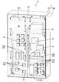
- FIG. 1 is a perspective view schematically showing a configuration inside a housing of an electric device according to an embodiment.
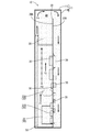
- FIG. 2 is a side view schematically showing the configuration inside the housing of the electric device.
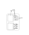
- FIG. 3 is a perspective view showing an example of a mounting mode of electronic components.
- the electric device includes a housing, a circuit board arranged inside the housing, and at least one electronic component arranged inside the housing and generating heat by energization.
- the inside of the housing is filled with an insulating liquid refrigerant
- the circuit board is arranged so that the normal line of the substrate surface, which is the plate surface of the circuit board, is horizontal
- the electronic component is the electronic component. It is arranged on the lower side of the housing and is immersed in the insulating liquid refrigerant.
- the live part (heat generation part) of the electronic component is directly cooled by the insulating liquid refrigerant.
- the heat released from the electronic components arranged on the lower side of the housing is transferred to the insulating liquid refrigerant, and the warmed insulating liquid refrigerant rises along the substrate surface of the circuit board.
- natural convection of the insulating liquid refrigerant is generated inside the housing, heat is dispersed in the housing, and a local temperature rise in the electrical equipment is suppressed.
- at least a part of the electronic component may be immersed in the insulating liquid refrigerant, and when the electronic component has a plurality of electronic components, at least one electronic component is arranged on the lower side of the housing. Just do it.
- the electric device according to the present disclosure preferably includes a plurality of the electronic components, and the electronic components are preferably mounted on both the substrate surface of one and the substrate surface of the other.
- the content of dust particles per unit volume of the insulating liquid refrigerant is preferably lower than the content of dust particles per unit volume of air.
- dust particles floating in the housing may cause a short circuit between the active parts of electronic parts such as electronic parts arranged inside the housing, which may cause a malfunction.
- the dust particles floating in the housing are reduced as compared with the conventional configuration not filled with the insulating liquid refrigerant, and the possibility of short circuit due to the dust particles is reduced. This makes it possible to increase the mounting density of electronic components and reduce the size of electrical equipment as compared with the conventional configuration.
- the housing is preferably made of a material containing metal.
- the housing since the housing has high thermal conductivity, the heat transferred from the electronic component to the insulating liquid refrigerant is transferred from the insulating liquid refrigerant to the housing and further to the outside. It becomes easier to convey. As a result, the heat dissipation of the electric device is improved and the temperature rise is suppressed.
- a flow path through which the insulating liquid refrigerant can flow is formed between the housing and the electronic component.
- the insulating liquid refrigerant flows between the housing and the electronic components, so that the insulating liquid refrigerant satisfactorily convects in the housing and the heat dispersibility is improved. Further, since the insulating liquid refrigerant flows along the housing, heat is easily transferred from the insulating liquid refrigerant to the housing, and heat dissipation is improved. As a result, the temperature rise of the electric device is suppressed.
- the electric device further includes a bus bar formed in a flat plate shape containing metal, and the bus bar and the electronic component are connected via a metal member formed containing metal. It is preferable to have.
- the heat from the electronic component is transferred to the bus bar via the metal member having high thermal conductivity. Then, the heat transferred to the bus bar is transferred from the surface of the bus bar having a large specific surface area to the insulating liquid refrigerant in contact with the surface. As a result, the heat from the electronic components is promptly transferred to the insulating liquid refrigerant, and the heat dispersibility and heat dissipation of the electric equipment are improved.
- the bus bar has a long longitudinal shape in one direction and is arranged so that the longitudinal direction is along the vertical direction.
- the heat transferred to the bus bar is transferred from the bottom to the top and dispersed even inside the bus bar having a high thermal conductivity. As a result, the heat dispersibility inside the electric device is further improved.
- the bus bar is arranged so that the plate surface of the bus bar is perpendicular to the substrate surface of the circuit board.
- the insulating liquid refrigerant flows along the substrate surface of the circuit board and the plate surface of the bus bar, and the flow of the insulating liquid refrigerant is adjusted.
- the insulating liquid refrigerant convects more smoothly inside the housing 11, and the heat dispersibility and heat dissipation of the electric device are improved.
- FIGS. 1 to 3 The embodiments of the present disclosure will be described with reference to FIGS. 1 to 3.
- the upper side in FIGS. 1 and 2 will be on top
- the left side in front of the paper in FIG. 1 will be the front
- the left side in FIG. 2 will be the front
- the left side in the back of the paper in FIG. 1 will be the back side of the paper in FIG.
- a reference numeral may be added to only a part of the members, and the reference numerals of other members may be omitted.
- the electric device 10 mounted on a vehicle such as an automobile will be illustrated.
- the electric device 10 is a device including a switching type DC-DC converter (DC voltage converter) that converts an input DC voltage into a predetermined level DC voltage and outputs the DC voltage, and has a well-known circuit configuration. ..
- the circuit configuration according to this embodiment is not particularly limited, but is a first converter that converts a DC voltage into an AC voltage, a transformer that transforms the AC voltage, and a second converter that converts the AC voltage into a DC voltage. It is equipped with a converter and is configured with a rectifying circuit that regulates the output voltage, a resonance circuit, a smoothing circuit, and the like.
- the transformer may be one that raises or lowers the voltage, but the electric device 10 according to the present embodiment includes a step-down converter that lowers the voltage by the transformer.
- the switching element according to the first converter may be referred to as a high voltage side switching element
- the switching element according to the second converter may be referred to as a low voltage side switching element.
- the electric device 10 includes a housing 11 and a circuit board 20 arranged inside the housing 11.
- the electronic component 30 is attached to the circuit board 20, and the inside of the housing 11 is filled with the insulating liquid refrigerant 40.
- the electric device 10 is mounted on the vehicle in the posture shown in FIGS. 1 and 2, that is, in a posture in which the normals of the substrate surfaces 20A and 20B of the circuit board 20 are horizontal.
- the housing 11 has a rectangular parallelepiped deep box-shaped main body 11M that opens upward, and a lid 11L that closes the upper opening of the main body 11M.
- the main body 11M and the lid 11L are made of a material containing a metal such as aluminum or stainless steel.
- the metal it is preferable that the metal is formed of a material containing a metal having a high thermal conductivity such as aluminum or an aluminum alloy, and in some cases, a stainless steel surface coated with copper or nickel is used. May be good.
- a copper alloy may be used or copper plating may be applied to the lid 11L having a relatively small surface area so that the lid 11L functions as a heat sink.
- the main body 11M has a rectangular bottom wall and four side walls rising from the peripheral edge of the bottom wall, and is integrally formed in a size capable of accommodating the circuit board 20. It is preferable that the lid 11L can close the opening of the main body 11M in a watertight manner.
- circuit board 20 As shown in FIGS. 1 and 2, a rectangular flat plate-shaped circuit board 20 is housed inside the housing 11.
- the circuit board 20 is a flat plate-shaped member having a well-known structure in which a conductive path is formed on a mounting surface of an insulating plate made of, for example, an insulating material by a printed wiring technique.
- the conductive path is formed of a material containing a metal such as copper.
- the circuit board 20 is arranged inside the housing 11 in a posture in which the normals of the board surfaces 20A and 20B, which are the plate surfaces of the circuit board 20, are horizontal.
- the circuit board 20 is housed inside the housing 11 in a so-called vertical posture in which the board surfaces 20A and 20B extend in the vertical direction.
- a gap (flow path) through which the insulating liquid refrigerant 40 can flow is formed.
- one board surface 20A and the other board surface 20B are used as mounting surfaces, and electronic components 30 are mounted on both board surfaces 20A and 20B of the circuit board 20.
- a bus bar 51 is arranged so as to extend vertically at the center position in the left-right direction of the substrate surface 20A.
- the electronic component 30 includes, for example, a resistor, a coil, a capacitor, a fuse, a relay, a diode, an IC (Integrated Circuit), a switching element such as a FET (Field Effect Transistor), and the like. More specifically, as shown in FIGS.
- a high-voltage side FET 31A which is a high-voltage side switching element
- a low-voltage side FET 31B which is a low-voltage side switching element
- a transformer 32 and a resonance coil 33A constituting a resonance circuit
- a choke coil 33B and the like are included.
- the electronic component 30 is arranged on the lower side inside the housing 11. As shown in FIGS. 1 and 2, the electric device 10 according to the present embodiment has a plurality of electronic components 30, and the plurality of electronic components 30 are generally below the substrate surfaces 20A and 20B. It is mounted in position. When the electrical device 10 has a plurality of electronic components 30, at least one electronic component 30 is below the height of 1/2, preferably below 1/3 in the vertical direction inside the housing 11. , More preferably located below the height of 1/4. In this way, by arranging the electronic component 30 which is a heat generating component on the lower side inside the housing 11, the insulating liquid refrigerant 40 located at the lower part in the housing 11 is heated and rises by the heat generated when the power is turned on.
- the high voltage side FET 31A, the low voltage side FET 31B, and the transformer 32 including a plurality of coils are arranged at the lowermost part in the housing 11.
- the transformer 32 including a plurality of coils are arranged at the lowermost part in the housing 11.
- a choke coil 33B is mounted.
- the switching element and the coil generate a particularly large amount of heat when energized and are relatively small.
- the circuit configuration of the DC-DC converter assuming that the amount of heat generated from all the electronic components 30 when energized is 100%, the total of four high-voltage side FETs 31A is 25% or more, and the low-voltage side FET 31B is six.
- the three types of electronic components 30 (high voltage side FET 31A, low voltage side FET 31B, transformer 32) having the largest heat generation are arranged at the bottom of the housing 11, and the heat generation amount is next to them at the position directly above them.
- a large resonance coil 33A and a choke coil 33B are arranged.
- the electronic component 30 is mounted on the substrate surface 20A or the substrate surface 20B, which is the mounting surface of the circuit board 20, in a known manner by a known method such as soldering, and is formed of a material containing metal on the substrate surfaces 20A, 20B. It is electrically connected to the conductive path.
- FIG. 3 shows a mounting mode of the FET 31 constituting the high voltage side FET 31A and the low voltage side FET 31B.
- the FET 31 has a main body portion 31M in which an element is built, and a terminal portion 31L provided so as to project to the outside of the main body portion 31M.
- FIG. 3 shows a mounting mode of the FET 31 constituting the high voltage side FET 31A and the low voltage side FET 31B.
- the FET 31 has a main body portion 31M in which an element is built, and a terminal portion 31L provided so as to project to the outside of the main body portion 31M.
- FIG. 3 shows a three-terminal type FET 31 in which three terminal portions 31L are projected, but the FET 31 is not limited to such a shape.
- a land 52 is formed in a part of the electric circuit stretched around the board surface 20A and the board surface 20B, and the protruding end of the terminal portion 31L is connected to the land 52 by soldering or the like.
- the bus bar 51 which will be described later, is electrically connected to a conductive path formed on the substrate surface 20A, and the electronic component 30 and the bus bar 51 mounted on the substrate surface 20A are formed with a land 52 containing metal. It is connected via a conductive path including.
- the inside of the housing 11 is filled with the insulating liquid refrigerant 40.
- the insulating liquid refrigerant 40 fills the inside of the housing 11 so that the entire circuit board 20 is immersed.
- the insulating liquid refrigerant 40 does not have to completely fill the inside of the housing 11, and the electronic component 30 may be immersed in the insulating liquid refrigerant 40.
- the insulating liquid refrigerant 40 is a liquid refrigerant having no conductivity.
- the insulating liquid refrigerant 40 for example, perfluorocarbon, hydrofluoroether, hydrofluoroketone, and a fluorine-based inert liquid can be used. Specific examples thereof include Novec (registered trademark) and Fluorinert (registered trademark) manufactured by 3M Japan Ltd. and Galden (registered trademark) manufactured by Solvay. Considering the burden on the environment, the use of hydrofluoroether-based Novec is particularly preferable.
- the insulating liquid refrigerant 40 in the present embodiment, a material having a dust particle content per unit volume lower than that of air per unit volume is used.
- a material having a dust particle content per unit volume lower than that of air per unit volume is used.
- air is a gas that is normally considered to be present in the vicinity of the electronic component 30 if the electronic component 30 is not immersed in the insulating liquid refrigerant 40.
- a short circuit may occur due to tracking.
- the insulating liquid refrigerant 40 having a dust particle content per unit volume lower than that of air By using the insulating liquid refrigerant 40 having a dust particle content per unit volume lower than that of air, the distance between the live parts required to avoid a short circuit is reduced. Therefore, it is possible to reduce the size of the electric device 10 by reducing the distance between the electronic components 30.
- the insulating liquid refrigerant 40 in the present embodiment, a refrigerant having a dielectric strength larger than that of air is used.
- the dielectric strength of air is about 3 kV / mm, while the dielectric strength of Novec is about 16 kV / mm.
- bus bar 51 As shown in FIGS. 1 and 2, a bus bar 51 is arranged on the substrate surface 20A of the circuit board 20.
- the bus bar 51 is a conductive member formed in a long rectangular plate shape in one direction by press-molding or forming a metal plate material.
- a bus bar 51 which is made of a material containing copper and has a very high thermal conductivity, is used.
- the bus bar 51 is arranged on the substrate surface 20A so that the longitudinal directions coincide with each other in the vertical direction and the plate surface is perpendicular to the substrate surface 20A, and the bus bar 51 is arranged on the substrate surface 20A. It is electrically connected to the conductive path formed in.
- the bus bar 51 and the electronic component 30 are connected via a metal member such as a conductive path including the land 52.
- the insulating liquid refrigerant 40 is placed between the front end edge of the bus bar 51 and the inner surface of the front wall of the main body 11M of the housing 11 in a state of being arranged on the substrate surface 20A. A flowable gap is formed.
- the bus bar 51 is arranged at the center position in the left-right direction of the substrate surface 20A, and the high-voltage side FET 31A and the choke coil 33B mounted on the substrate surface 20A and the low-voltage side. It is located between the FET 31B, the transformer 32 and the resonance coil 33A.
- the plurality of electronic components 30 having a particularly large calorific value are arranged on the substrate surface 20A in a state of being separated to the left and right of the bus bar 51.
- the temperature of the insulating liquid refrigerant 40 to which heat has been transferred rises and the specific gravity decreases, the temperature rises as shown by the arrow F1.
- the insulating liquid refrigerant 40 further rises along the bus bar 51 like arrows F2 and F3.
- the insulating liquid refrigerant 40 that has risen while sprinkling the surrounding insulating liquid refrigerant 40 to generate an ascending flow reaches the vicinity of the uppermost liquid level (in this embodiment, the lower surface of the lid 11L of the housing 11), It moves to the left and right ends of the housing 11 along the liquid surface (lower surface of the lid 11L) like the arrow lines F4 and F5.
- the heat of the insulating liquid refrigerant 40 that reaches the lower surface of the lid 11L is transferred to the lid 11L having a high thermal conductivity made of a material containing metal, and is dissipated from the upper surface of the lid 11L to the outside of the housing 11. Will be done.
- the temperature of the insulating liquid refrigerant 40 decreases and the specific gravity increases, so that the insulating liquid refrigerant 40 descends along the side wall of the main body 11M of the housing 11 like arrows F6 and F7.
- the descending insulating liquid refrigerant 40 entrains the surrounding insulating liquid refrigerant 40 to generate a descending flow.
- the main body 11M is also formed of a material containing metal and has high thermal conductivity, the heat of the insulating liquid refrigerant 40 is transferred to the side wall of the main body 11M and dissipated from the outer surface of the side wall to the outside of the housing 11. .. As a result, the temperature of the insulating liquid refrigerant 40 is further lowered.
- the insulating liquid refrigerant 40 that has moved to the bottom wall of the main body 11M moves along the lower wall and flows into the vicinity of the electronic component 30 as shown by the arrow line F8.
- the insulating liquid refrigerant 40 flowing into the vicinity of the high-voltage side FET 31A, the low-voltage side FET 31B, and the transformer 32 arranged at the lowermost part dissipates heat to the outside of the housing 11 via the lid 11L, the side wall of the main body 11M, and the like. Therefore, the temperature has dropped.
- the insulating liquid refrigerant 40 When the insulating liquid refrigerant 40 whose temperature has been lowered in this way comes into contact with the electronic components 30 having a large calorific value such as the high-pressure side FET 31A, the low-pressure side FET 31B, and the transformer 32, the heat generated from these comes into contact with the insulating liquid again. It is transmitted to the refrigerant 40.
- the insulating liquid refrigerant 40 to which the heat transferred from the electronic component 30 is transferred rises again as shown by the arrow line F1. Even on the substrate surface 20B side, convection of the insulating liquid refrigerant 40 occurs in response to heat generation from the electronic component 30 or the like.
- the insulating liquid refrigerant 40 can be relatively freely distributed in the entire housing 11 including the space between the substrate surface 20A side and the substrate surface 20B side through these gaps. Has been done.
- the insulating liquid refrigerant 40 convects the inside of the housing 11 while directly cooling the live part of the electronic component 30, so that heat is dispersed inside the electric device 10 and the lid 11L and the main body are used. Heat is dissipated to the outside of the housing 11 via the side wall of the 11M or the like.
- the heat generated from the electronic component 30 is also dispersed by a route via a metal member having high thermal conductivity such as a conductive path including a land 52 formed of a material containing metal.
- a metal member having high thermal conductivity such as a conductive path including a land 52 formed of a material containing metal.
- the heat generated in the FET 31 is transmitted from the terminal portion 31L to the land 52. Then, it is transmitted to the conductive path including the land 52 formed on the substrate surface 20A, and further to the bus bar 51 connected to the conductive path.
- the heat transferred to the bus bar 51 moves upward inside the bus bar 51.
- the heat inside the bus bar 51 moves from the lower side to the upper side along the longitudinal direction. , Is transmitted from the surface of the bus bar 51 to the insulating liquid refrigerant 40.
- the insulating liquid refrigerant 40 whose heat is transferred from the bus bar 51 and whose temperature rises and whose specific gravity becomes small rises along the bus bar 51 as arrows F1, F2, and F3.
- convection of the insulating liquid refrigerant 40 similar to that described above occurs, and heat is dispersed inside the electric device 10. Then, the heat of the insulating liquid refrigerant 40 is dissipated to the outside of the housing 11 via the lid 11L, the side wall of the main body 11M, and the like.
- the electric device 10 has an extremely excellent heat dispersibility and heat dissipation property while having a simple structure.
- the electric device 10 includes a housing 11, a circuit board 20 arranged inside the housing 11, and at least one electronic component 30 arranged inside the housing 11 that generates heat when energized.
- the inside of the housing 11 is filled with an insulating liquid refrigerant 40, and the circuit board 20 is arranged so that the normal lines of the substrate surfaces 20A and 20B, which are the plate surfaces of the circuit board 20, are horizontal.
- the electronic component 30 is arranged on the lower side of the housing 11 and is immersed in the insulating liquid refrigerant 40.
- the live part of the electronic component 30 can be directly cooled by the insulating liquid refrigerant 40.
- the heat released from the electronic component 30 arranged on the lower side of the housing 11 is transferred to the insulating liquid refrigerant 40, and the warmed insulating liquid refrigerant 40 is along the substrate surfaces 20A and 20B of the circuit board 20. And rise.
- natural convection of the insulating liquid refrigerant 40 is generated inside the housing 11, heat is dispersed in the housing 11, and a local temperature rise in the electric device 10 is suppressed.
- the electronic component 30 includes a semiconductor switching element such as a FET 31. Further, the electronic component 30 includes an element such as a transformer 32 having a coil and a coil 33.
- the semiconductor switching element such as the FET 31, the transformer 32, and the coil 33 have a large amount of heat generation among the electronic components 30 used in the electric device 10.
- the electric device 10 includes a plurality of electronic components 30, and the electronic components 30 are mounted on both substrate surfaces 20A and 20B of one substrate surface 20A and the other substrate surface 20B.
- the configuration of the present embodiment by mounting the electronic components on both of the two plate surfaces of the circuit board 20, a plurality of electrons are mounted as compared with the configuration in which the electronic components are mounted on only one board surface.
- the area of the circuit board 20 required to mount the component 30 is reduced. This makes it possible to reduce the size of the circuit board 20 and thus the electric device 10 while suppressing an increase in the mounting density of the electronic component 30.
- the content of dust particles per unit volume of the insulating liquid refrigerant 40 is lower than the content of dust particles per unit volume of air.
- the dust particles floating in the housing 11 are reduced as compared with the electric device having the conventional configuration not filled with the insulating liquid refrigerant 40, and the dust particles may cause a short circuit.
- the sex is reduced. This makes it possible to increase the mounting density of the electronic component 30 and reduce the size of the electric device 10 as compared with the conventional configuration.
- the housing 11 is made of a material containing metal.
- the housing 11 since the housing 11 has a high thermal conductivity, the heat transferred from the electronic component 30 to the insulating liquid refrigerant 40 is further transferred from the insulating liquid refrigerant 40 to the housing 11. Is easy to be transmitted to the outside. As a result, the heat dissipation of the electric device 10 is improved, and the temperature rise of the electric device 10 is suppressed.
- a flow path through which the insulating liquid refrigerant 40 can flow is formed between the housing 11 and the electronic component 30.
- the insulating liquid refrigerant 40 flows between the housing 11 and the electronic component 30, so that the insulating liquid refrigerant 40 satisfactorily convects in the housing 11 and has thermal dispersibility. Is improved. Further, since the insulating liquid refrigerant 40 flows along the housing 11, heat is easily transferred from the insulating liquid refrigerant 40 to the housing 11, and heat dissipation is improved. As a result, the temperature rise of the electric device 10 is suppressed.
- the electric device 10 further includes a bus bar 51 formed in a flat plate shape containing metal, and the bus bar 51 and the electronic component 30 are connected via a metal member formed containing metal. There is.
- the heat from the electronic component 30 is transferred to the bus bar 51 via a metal member having a high thermal conductivity such as a conductive path including the land 52. Then, the heat transferred to the bus bar 51 is transferred to the insulating liquid refrigerant 40 from the surface of the bus bar 51 having a high thermal conductivity and a large specific surface area. As a result, the heat generated in the electronic component 30 is quickly transferred to the insulating liquid refrigerant 40, and the heat dispersibility and heat dissipation of the electric device 10 are improved.
- the bus bar 51 has a long longitudinal shape in one direction, and is arranged so that the longitudinal direction is along the vertical direction.
- the heat transferred to the bus bar 51 is transferred from the bottom to the top and dispersed even inside the bus bar 51 having a high thermal conductivity. As a result, the heat dispersibility inside the electric device is further improved.
- the bus bar 51 is arranged so that the plate surface of the bus bar 51 is perpendicular to the substrate surface 20A of the circuit board 20.
- the insulating liquid refrigerant 40 flows while being guided by the substrate surface 20A of the circuit board 20 and the plate surface of the bus bar 51, and the flow of the insulating liquid refrigerant 40 is adjusted.
- the insulating liquid refrigerant 40 is more smoothly convected inside the housing 11, and the heat dispersibility and heat dissipation of the electric device 10 are improved.
- the electronic component 30 is not limited to the above.
- the dimensional shape, number, and arrangement of each electronic component 30 described in the above embodiment are only examples.
- the circuit board 20 is not limited to the one arranged as described above.
- the circuit board 20 is arranged rearward in the front-rear direction of the housing 11, and the electronic component 30 having a relatively large calorific value is mounted on the board surface 20A which is the front plate surface of the circuit board 20. ..
- the circuit board may be arranged in the center of the housing in the front-rear direction, and the electronic components 30 having a large calorific value may be dispersed and arranged on both the substrate surface and the other substrate surface.
- the circuit board 20 and the housing 11 are not limited to those having the above-mentioned dimensions and shape.
- the vertically long circuit board 20 and the housing 11 in which the vertical height dimension is larger than the left and right width dimension are described.
- a horizontally long circuit board and a housing in which the left and right width dimensions are larger than the top and bottom height dimensions may be used.
- bus bars 51 are not limited to those described above.
- a plurality of bus bars may be arranged on both the substrate surface of one substrate surface and the other substrate surface of the circuit board.
- a plurality of bus bars may be arranged side by side in parallel so as to extend in the vertical direction at intervals in the left-right direction on one board surface or both board surfaces of the circuit board. By doing so, the flow of the insulating liquid refrigerant can be further adjusted.
- the electrical device 10 is not limited to those including a DC-DC converter.
- this technology can be applied to an AC-DC converter, an electric connection box, a distribution box, an ECU, and the like.
Landscapes
- Engineering & Computer Science (AREA)
- Microelectronics & Electronic Packaging (AREA)
- Physics & Mathematics (AREA)
- Thermal Sciences (AREA)
- Cooling Or The Like Of Electrical Apparatus (AREA)
- Casings For Electric Apparatus (AREA)
Priority Applications (2)
| Application Number | Priority Date | Filing Date | Title |
|---|---|---|---|
| US18/013,950 US12484201B2 (en) | 2020-07-03 | 2021-06-17 | Electric device with immersed electronic components and elongated busbar forming an upward flow |
| CN202180042507.1A CN115715489A (zh) | 2020-07-03 | 2021-06-17 | 电气设备 |
Applications Claiming Priority (2)
| Application Number | Priority Date | Filing Date | Title |
|---|---|---|---|
| JP2020115388A JP7419994B2 (ja) | 2020-07-03 | 2020-07-03 | 電気機器 |
| JP2020-115388 | 2020-07-03 |
Publications (1)
| Publication Number | Publication Date |
|---|---|
| WO2022004400A1 true WO2022004400A1 (ja) | 2022-01-06 |
Family
ID=79316091
Family Applications (1)
| Application Number | Title | Priority Date | Filing Date |
|---|---|---|---|
| PCT/JP2021/022971 Ceased WO2022004400A1 (ja) | 2020-07-03 | 2021-06-17 | 電気機器 |
Country Status (4)
| Country | Link |
|---|---|
| US (1) | US12484201B2 (enExample) |
| JP (1) | JP7419994B2 (enExample) |
| CN (1) | CN115715489A (enExample) |
| WO (1) | WO2022004400A1 (enExample) |
Cited By (1)
| Publication number | Priority date | Publication date | Assignee | Title |
|---|---|---|---|---|
| EP4468337A1 (en) * | 2023-05-26 | 2024-11-27 | Hitachi Energy Ltd | Semiconductor power module, semiconductor power package and method for manufacturing a semiconductor power module |
Families Citing this family (3)
| Publication number | Priority date | Publication date | Assignee | Title |
|---|---|---|---|---|
| US12402272B2 (en) * | 2021-01-12 | 2025-08-26 | Cooler Master Co., Ltd. | Single-phase immersion cooling system and method of the same |
| DE102021130926B4 (de) * | 2021-11-25 | 2025-08-14 | Dr. Ing. H.C. F. Porsche Aktiengesellschaft | Flüssigkeitsgekühlte Leistungselektronikeinheit |
| JP7715062B2 (ja) * | 2022-03-14 | 2025-07-30 | 株式会社豊田自動織機 | 電気機器 |
Citations (5)
| Publication number | Priority date | Publication date | Assignee | Title |
|---|---|---|---|---|
| JPS60249351A (ja) * | 1984-05-24 | 1985-12-10 | Fujitsu Ltd | 沸騰冷却型回路基板と冷媒液中での配置構造 |
| JPS6285449A (ja) * | 1985-10-09 | 1987-04-18 | Fujitsu Ltd | 半導体装置の冷却構造 |
| JPS62293653A (ja) * | 1986-06-12 | 1987-12-21 | Fujitsu Ltd | 冷媒クリ−ニング装置 |
| JP2017147881A (ja) * | 2016-02-18 | 2017-08-24 | 株式会社オートネットワーク技術研究所 | 電気機器 |
| JP2019220527A (ja) * | 2018-06-18 | 2019-12-26 | 富士通株式会社 | 液浸冷却用熱交換器 |
Family Cites Families (18)
| Publication number | Priority date | Publication date | Assignee | Title |
|---|---|---|---|---|
| JPH0745761A (ja) * | 1993-07-30 | 1995-02-14 | Takeo Yoshino | 液冷式ハイブリッドic |
| US6052284A (en) * | 1996-08-06 | 2000-04-18 | Advantest Corporation | Printed circuit board with electronic devices mounted thereon |
| JP3855382B2 (ja) * | 1997-08-06 | 2006-12-06 | 株式会社デンソー | 冷凍サイクル装置 |
| JP2005317798A (ja) * | 2004-04-28 | 2005-11-10 | Toshiba Corp | 電子機器 |
| US7393236B2 (en) * | 2005-09-02 | 2008-07-01 | Gm Global Technology Operations, Inc. | Integrated thermal and electrical connection system for power devices |
| CN201243015Y (zh) * | 2008-03-04 | 2009-05-20 | 无锡爱迪信光电科技有限公司 | 大功率发光二极管的液体散热装置 |
| CN101588707A (zh) * | 2008-05-19 | 2009-11-25 | 华为技术有限公司 | 一种散热装置及应用其的电子设备 |
| JP5109812B2 (ja) * | 2008-05-30 | 2012-12-26 | 住友電装株式会社 | 電気接続箱 |
| US8369090B2 (en) * | 2009-05-12 | 2013-02-05 | Iceotope Limited | Cooled electronic system |
| KR20150111753A (ko) * | 2014-03-26 | 2015-10-06 | 박일권 | 발광다이오드 조명장치 |
| WO2017001582A2 (en) * | 2015-06-30 | 2017-01-05 | CommScope Connectivity Belgium BVBA | System for compensation of expansion/contraction of a cooling medium inside a sealed closure |
| US10347608B2 (en) * | 2016-05-27 | 2019-07-09 | General Electric Company | Power module |
| JP2019029539A (ja) * | 2017-07-31 | 2019-02-21 | 株式会社ケーヒン・サーマル・テクノロジー | 半導体冷却装置 |
| CN108563305B (zh) * | 2018-01-29 | 2023-12-19 | 广东西江数据科技有限公司 | 一种喷淋式液冷服务器 |
| JP2019140247A (ja) | 2018-02-09 | 2019-08-22 | 日本電気株式会社 | 冷却装置及び電子機器 |
| JP7011221B2 (ja) | 2018-03-28 | 2022-01-26 | 日本電気株式会社 | 実装基板、電子機器及び素子冷却方法 |
| JP2020088090A (ja) | 2018-11-21 | 2020-06-04 | アイシン・エィ・ダブリュ株式会社 | 電力変換装置用冷却装置 |
| CN110536586B (zh) * | 2019-06-13 | 2024-01-30 | 刘一航 | 一种浸没式冷却装置 |
-
2020
- 2020-07-03 JP JP2020115388A patent/JP7419994B2/ja active Active
-
2021
- 2021-06-17 CN CN202180042507.1A patent/CN115715489A/zh active Pending
- 2021-06-17 US US18/013,950 patent/US12484201B2/en active Active
- 2021-06-17 WO PCT/JP2021/022971 patent/WO2022004400A1/ja not_active Ceased
Patent Citations (5)
| Publication number | Priority date | Publication date | Assignee | Title |
|---|---|---|---|---|
| JPS60249351A (ja) * | 1984-05-24 | 1985-12-10 | Fujitsu Ltd | 沸騰冷却型回路基板と冷媒液中での配置構造 |
| JPS6285449A (ja) * | 1985-10-09 | 1987-04-18 | Fujitsu Ltd | 半導体装置の冷却構造 |
| JPS62293653A (ja) * | 1986-06-12 | 1987-12-21 | Fujitsu Ltd | 冷媒クリ−ニング装置 |
| JP2017147881A (ja) * | 2016-02-18 | 2017-08-24 | 株式会社オートネットワーク技術研究所 | 電気機器 |
| JP2019220527A (ja) * | 2018-06-18 | 2019-12-26 | 富士通株式会社 | 液浸冷却用熱交換器 |
Cited By (2)
| Publication number | Priority date | Publication date | Assignee | Title |
|---|---|---|---|---|
| EP4468337A1 (en) * | 2023-05-26 | 2024-11-27 | Hitachi Energy Ltd | Semiconductor power module, semiconductor power package and method for manufacturing a semiconductor power module |
| WO2024245849A1 (en) * | 2023-05-26 | 2024-12-05 | Hitachi Energy Ltd | Semiconductor power module, semiconductor power package and method for manufacturing a semiconductor power module |
Also Published As
| Publication number | Publication date |
|---|---|
| JP2022013081A (ja) | 2022-01-18 |
| US20230292473A1 (en) | 2023-09-14 |
| JP7419994B2 (ja) | 2024-01-23 |
| US12484201B2 (en) | 2025-11-25 |
| CN115715489A (zh) | 2023-02-24 |
Similar Documents
| Publication | Publication Date | Title |
|---|---|---|
| WO2022004400A1 (ja) | 電気機器 | |
| US8995130B2 (en) | Power supply unit using housing in which printed circuit board is housed | |
| US10178754B2 (en) | Circuit board module and electronic device | |
| JP5005462B2 (ja) | 電気接続箱 | |
| JP5469270B1 (ja) | 電子機器 | |
| US20200051765A1 (en) | Electric apparatus | |
| JP6906709B2 (ja) | 電力変換器 | |
| US20210136948A1 (en) | Power conversion apparatus | |
| JP6486443B1 (ja) | 電力変換装置 | |
| CN103931094A (zh) | 功率转换装置 | |
| JP7527446B2 (ja) | 電力変換装置 | |
| JP7074486B2 (ja) | 二次電池モジュール | |
| JP2019046849A (ja) | 車載機器の熱分散構造 | |
| CN103907276A (zh) | 电力转换装置 | |
| KR102386318B1 (ko) | 커패시터 직접냉각방식의 인버터 | |
| JPH10126924A (ja) | 電気接続装置 | |
| US11778773B2 (en) | Choke structure with water cooling | |
| WO2020080248A1 (ja) | 回路構造体及び電気接続箱 | |
| WO2023203754A1 (ja) | コンデンサユニットおよび電子機器 | |
| JP7039779B2 (ja) | 空冷機構付き電子機器 | |
| WO2017170184A1 (ja) | 電力変換装置 | |
| CN206865896U (zh) | 一种应用于dcdc变换器的半封闭外壳结构 | |
| JP2008118774A (ja) | バスバー | |
| JP7466850B2 (ja) | 車載充電器およびインバータ | |
| KR102710795B1 (ko) | 전력 변환 장치 |
Legal Events
| Date | Code | Title | Description |
|---|---|---|---|
| 121 | Ep: the epo has been informed by wipo that ep was designated in this application |
Ref document number: 21830907 Country of ref document: EP Kind code of ref document: A1 |
|
| NENP | Non-entry into the national phase |
Ref country code: DE |
|
| 122 | Ep: pct application non-entry in european phase |
Ref document number: 21830907 Country of ref document: EP Kind code of ref document: A1 |
|
| WWG | Wipo information: grant in national office |
Ref document number: 18013950 Country of ref document: US |