WO2021260937A1 - Uボルト取り付け治具、およびuボルト取り付け方法 - Google Patents
Uボルト取り付け治具、およびuボルト取り付け方法 Download PDFInfo
- Publication number
- WO2021260937A1 WO2021260937A1 PCT/JP2020/025320 JP2020025320W WO2021260937A1 WO 2021260937 A1 WO2021260937 A1 WO 2021260937A1 JP 2020025320 W JP2020025320 W JP 2020025320W WO 2021260937 A1 WO2021260937 A1 WO 2021260937A1
- Authority
- WO
- WIPO (PCT)
- Prior art keywords
- bolt
- mounting
- fitting
- operator
- holding
- Prior art date
- Legal status (The legal status is an assumption and is not a legal conclusion. Google has not performed a legal analysis and makes no representation as to the accuracy of the status listed.)
- Ceased
Links
Images







Classifications
-
- B—PERFORMING OPERATIONS; TRANSPORTING
- B25—HAND TOOLS; PORTABLE POWER-DRIVEN TOOLS; MANIPULATORS
- B25H—WORKSHOP EQUIPMENT, e.g. FOR MARKING-OUT WORK; STORAGE MEANS FOR WORKSHOPS
- B25H7/00—Marking-out or setting-out work
- B25H7/02—Plates having a flat surface
-
- B—PERFORMING OPERATIONS; TRANSPORTING
- B25—HAND TOOLS; PORTABLE POWER-DRIVEN TOOLS; MANIPULATORS
- B25B—TOOLS OR BENCH DEVICES NOT OTHERWISE PROVIDED FOR, FOR FASTENING, CONNECTING, DISENGAGING, OR HOLDING
- B25B23/00—Details of, or accessories for, spanners, wrenches, screwdrivers
- B25B23/02—Arrangements for handling screws or nuts
- B25B23/08—Arrangements for handling screws or nuts for holding or positioning screw or nut prior to or during its rotation
- B25B23/10—Arrangements for handling screws or nuts for holding or positioning screw or nut prior to or during its rotation using mechanical gripping means
-
- F—MECHANICAL ENGINEERING; LIGHTING; HEATING; WEAPONS; BLASTING
- F16—ENGINEERING ELEMENTS AND UNITS; GENERAL MEASURES FOR PRODUCING AND MAINTAINING EFFECTIVE FUNCTIONING OF MACHINES OR INSTALLATIONS; THERMAL INSULATION IN GENERAL
- F16L—PIPES; JOINTS OR FITTINGS FOR PIPES; SUPPORTS FOR PIPES, CABLES OR PROTECTIVE TUBING; MEANS FOR THERMAL INSULATION IN GENERAL
- F16L1/00—Laying or reclaiming pipes; Repairing or joining pipes on or under water
- F16L1/024—Laying or reclaiming pipes on land, e.g. above the ground
- F16L1/06—Accessories therefor, e.g. anchors
-
- F—MECHANICAL ENGINEERING; LIGHTING; HEATING; WEAPONS; BLASTING
- F16—ENGINEERING ELEMENTS AND UNITS; GENERAL MEASURES FOR PRODUCING AND MAINTAINING EFFECTIVE FUNCTIONING OF MACHINES OR INSTALLATIONS; THERMAL INSULATION IN GENERAL
- F16L—PIPES; JOINTS OR FITTINGS FOR PIPES; SUPPORTS FOR PIPES, CABLES OR PROTECTIVE TUBING; MEANS FOR THERMAL INSULATION IN GENERAL
- F16L3/00—Supports for pipes, cables or protective tubing, e.g. hangers, holders, clamps, cleats, clips, brackets
- F16L3/02—Supports for pipes, cables or protective tubing, e.g. hangers, holders, clamps, cleats, clips, brackets partly surrounding the pipes, cables or protective tubing
- F16L3/04—Supports for pipes, cables or protective tubing, e.g. hangers, holders, clamps, cleats, clips, brackets partly surrounding the pipes, cables or protective tubing and pressing it against a wall or other support
-
- F—MECHANICAL ENGINEERING; LIGHTING; HEATING; WEAPONS; BLASTING
- F16—ENGINEERING ELEMENTS AND UNITS; GENERAL MEASURES FOR PRODUCING AND MAINTAINING EFFECTIVE FUNCTIONING OF MACHINES OR INSTALLATIONS; THERMAL INSULATION IN GENERAL
- F16L—PIPES; JOINTS OR FITTINGS FOR PIPES; SUPPORTS FOR PIPES, CABLES OR PROTECTIVE TUBING; MEANS FOR THERMAL INSULATION IN GENERAL
- F16L3/00—Supports for pipes, cables or protective tubing, e.g. hangers, holders, clamps, cleats, clips, brackets
- F16L3/08—Supports for pipes, cables or protective tubing, e.g. hangers, holders, clamps, cleats, clips, brackets substantially surrounding the pipe, cable or protective tubing
- F16L3/12—Supports for pipes, cables or protective tubing, e.g. hangers, holders, clamps, cleats, clips, brackets substantially surrounding the pipe, cable or protective tubing comprising a member substantially surrounding the pipe, cable or protective tubing
- F16L3/1207—Supports for pipes, cables or protective tubing, e.g. hangers, holders, clamps, cleats, clips, brackets substantially surrounding the pipe, cable or protective tubing comprising a member substantially surrounding the pipe, cable or protective tubing the ends of the member and the fixing elements being placed on both sides of the pipe
Definitions
- This disclosure relates to a U-bolt mounting jig and a U-bolt mounting method.
- Patent Document 1 includes a U-bolt for fixing a pipe to a frame, a first support portion for supporting the pipe, and a saddle including a second support portion arranged between the pipe and the frame.
- a U-bolt structure that improves support rigidity and load capacity and allows fine adjustment of the saddle is disclosed.
- Non-Patent Document 1 discloses details of the size of the U-bolt 20.
- the bolt hole into which the U bolt is inserted is formed so as to be larger than the diameter of the U bolt.
- a U-bolt having a diameter of 9 mm as shown in FIG. 10B is inserted into a bolt hole having a length of 30 mm in the longitudinal direction and a length of 15 mm in the lateral direction as shown in FIG. 10A.
- An extra space of 10.5 mm is formed at both ends of the U bolt in the longitudinal direction, and 3 mm is formed at both ends of the U bolt in the lateral direction.
- the object of the present disclosure made in view of such circumstances is a U-bolt mounting jig and a U-bolt mounting jig that can mount a U-bolt vertically to a mounting member without increasing the number of parts even in a narrow place. To provide a bolt mounting method.
- the U-bolt mounting jig is a U-bolt mounting jig for mounting a U-bolt for fixing a pipeline to a mounting member, and the U-bolt inserted into a bolt hole provided in the mounting member.
- the first fitting member and the second fitting so that the straight line connecting the first fitting member and the second fitting member to be fitted to both ends of the bolt is parallel to the mounting member. It is characterized by including a holding member for holding the combined member.
- the U-bolt mounting method is a U-bolt mounting method for mounting a U-bolt for fixing a pipeline to a mounting member, and both ends of the U-bolt are provided in bolt holes provided in the mounting member.
- the step of inserting, the step of temporarily fastening the nut to the U bolt, the first fitting member and the second fitting member that are fitted to the both ends, and the straight line connecting the both ends are attached to the mounting member.
- a U-bolt mounting jig capable of mounting a U-bolt vertically to a mounting member without increasing the number of parts even in a narrow place, and a U-bolt mounting method. Can be done.
- the U-bolt is perpendicular to the mounting member
- the side portions of the U-bolt are arranged closer to the mounting member than the central portion of the U-bolt, and both ends of the U-bolt are designated. It is assumed that the straight line to be connected is parallel to the surface of the mounting member (at this time, the straight line portion of the U-bolt end is perpendicular to the mounting member).
- the U-bolt is slanted with respect to the mounting member means that the straight line connecting both ends of the U-bolt is tilted with respect to the surface of the mounting member.
- upward means a positive direction parallel to the Z axis of the coordinate axis display drawn in the drawing
- downward means the coordinate axis display drawn in the drawing. It shall mean a negative direction parallel to the Z axis of.
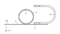
- the U-bolt attachment jig 100 is a jig for attaching the U-bolt 20 for fixing the pipeline 10 to the attachment member 300 attached to a structure such as a bridge.
- ⁇ member 300 is the surface S 1 is a plane, the conduit 10 may have a stable and capable of supporting a configuration.
- the supporting member 300 is made of, for example, L-shaped steel, flat steel, H-shaped steel, or the like.
- the ⁇ member 300, the bolt hole H 2 is provided with the other end of the bolt holes H 1 and U-bolts 20 one end of U-bolt 20 is inserted is inserted.
- the pipeline 10 is a resin or metal pipe, for example, a hard vinyl pipe, an FRP (Fiber Reinforced Plastics) pipe, a steel pipe, a FRPM (Fiberglass Reinforced Plastic Mortar) pipe, or the like.
- the pipeline 10 may have a cylindrical shape, and its configuration is not particularly limited.
- the pipeline 10 may be provided with a joint or the like and may have irregularities on the outside.
- the pipeline 10 may be provided with a protective piece 11 bonded with an adhesive to the outside (see FIG. 1).
- the pipeline 10 can be protected when the pipeline 10 is fixed to the mounting member 300 by the U bolt 20.
- FIG. 1 cites a case where one pipeline 10 is installed in the auxiliary member 300 as an example, but the number of pipelines 10 installed in the auxiliary member 300 is not particularly limited.
- the U-bolt 20 is a single steel material having a curved central portion, a linear shape at the side portions, and a bolt structure at both ends. U-bolt 20, both ends, is inserted into the bolt holes H 1 and bolt holes H 2, line 10, ⁇ member 300, and washers 21a, via 21b, nuts 22a, to 22b and screwed. As a result, the pipeline 10 is fixed to the attachment member 300.
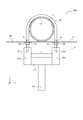
- the U-bolt mounting jig 100 includes a fitting member (first fitting member) 101a, a fitting member (second fitting member) 101b, and a holding member 102.
- the fitting member 101a is provided with a fitting portion 1011a.
- the fitting member 101b is provided with a fitting portion 1011b.
- the fitting members 101a and 101b are provided so as to be perpendicular to the mounting member 300.
- the fitting member 101a fits with one end of the U bolt 20 at the fitting portion 1011a
- the fitting member 101b fits with the other end of the U bolt 20 at the fitting portion 1011b.
- the distance L between the fitting member 101a and the fitting member 101b is set based on the size of the U bolt 20 (JIS standard). The operator appropriately selects and uses the U-bolt mounting jig 100 suitable for the size of the U-bolt 20.
- the holding member 102 is provided so as to be parallel to the mounting member 300.
- the holding member 102 holds the fitting members 101a and 101b so that the straight line D connecting both ends of the U bolt 20 is parallel to the mounting member 300.
- the holding member 102 is held in parallel with the mounting member 300, so that the straight line D connecting both ends of the U bolt 20 is connected to the mounting member. It can be parallel to 300.
- One end of the holding member 102 is joined to the fitting member 101a, and the other end is joined to the fitting member 101b.
- the joining method for joining the holding member 102 and the fitting members 101a and 101b is not particularly limited, and for example, bolt joining, welding joining, adhesive joining, or the like is used for joining.
- the operator attaches the U-bolt 20 perpendicularly to the mounting member 300 by fastening the nuts 22a and 22b to the U-bolt 20 via the washers 21a and 21b while pulling the holding member 102 downward. It becomes possible.
- the fitting members 101a and 101b that are fitted to both ends of the U-bolt 20 and the straight line D connecting both ends of the U-bolt 20 have a straight line D with respect to the mounting member 300.
- a holding member 102 for holding the fitting members 101a and 101b is provided so as to be parallel to each other.
- the worker lays the U bolt 20 on its side and installs it on the mounting member 300 (see FIG. 9A).
- the operator positions both ends of the U-bolt 20 so that the thread length l at one end of the U-bolt 20 and the thread length l at the other end of the U-bolt 20 are equal. Adjust (see FIG. 9C).
- the operator from the surface S 2 of the surface S 1 and the opposite side of the ⁇ member 300, via a washer 21a, is temporarily fastened to the nut 22a on one end of the U-bolt 20. Further, the operator, from the surface S 2 of the surface S 1 and the opposite side of the ⁇ member 300, via the washer 21b, temporarily fastening the nut 22b to the other end of the U-bolt 20 (see FIG. 9D).
- the operator attaches the U-bolt mounting jig 100 according to the first embodiment to the U-bolt 20 (see FIG. 1).
- the operator grips the holding member 102, while pulling downward, from the face S 2 of the surface S 1 and the opposite side of the ⁇ member 300, via a washer 21a, at one end of the U-bolt 20 concluded nuts 22a, from the surface S 1 and the opposite surface S 2 of ⁇ member 300, via the washer 21b, fastening a nut 22b to the other end of the U-bolt 20.
- the operator removes the U-bolt mounting jig 100 from the U-bolt 20, and completes the mounting work of the U-bolt 20.
- the U bolt 20 is attached to the attachment member 300, and the pipeline 10 is fixed to the attachment member 300.
- the U-bolt mounting method according to the first embodiment makes it possible to mount the U-bolt 20 vertically to the attachment member 300 without increasing the number of parts, even in a narrow place.
- the difference between the U-bolt mounting jig 100A according to the second embodiment and the U-bolt mounting jig 100 according to the first embodiment is that the U-bolt mounting jig 100 according to the first embodiment does not include a gripping member.
- the U-bolt mounting jig 100A according to the second embodiment is provided with a gripping member. Since the other configurations are the same as those of the U-bolt mounting jig 100 according to the first embodiment, duplicated description will be omitted.
- the grip member 103 is attached to the central portion of the holding member 102.
- the gripping member 103 preferably has a shape that is easy for an operator to grip by hand, and is composed of, for example, a rod-shaped member.
- the operator can mount the U-bolt 20 perpendicularly to the mounting member 300 without increasing the number of parts even in a narrow place. It will be possible.
- the worker lays the U bolt 20 on its side and installs it on the mounting member 300 (see FIG. 9A).
- the operator positions both ends of the U-bolt 20 so that the thread length l at one end of the U-bolt 20 and the thread length l at the other end of the U-bolt 20 are equal. Adjust (see FIG. 9C).
- the operator from the surface S 2 of the surface S 1 and the opposite side of the ⁇ member 300, via a washer 21a, is temporarily fastened to the nut 22a on one end of the U-bolt 20. Further, the operator, from the surface S 2 of the surface S 1 and the opposite side of the ⁇ member 300, via the washer 21b, temporarily fastening the nut 22b to the other end of the U-bolt 20 (see FIG. 9D).
- the operator attaches the U-bolt attachment jig 100A according to the second embodiment to the U-bolt 20 (see FIG. 2).
- the operator grips the grip member 103, while pulling downward, from the face S 2 of the surface S 1 and the opposite side of the ⁇ member 300, via a washer 21a, at one end of the U-bolt 20 concluded nuts 22a, from the surface S 1 and the opposite surface S 2 of ⁇ member 300, via the washer 21b, fastening a nut 22b to the other end of the U-bolt 20.
- the operator removes the U-bolt mounting jig 100A from the U-bolt 20, and completes the mounting work of the U-bolt 20.
- the U bolt 20 is attached to the attachment member 300, and the pipeline 10 is fixed to the attachment member 300.
- the U-bolt mounting method according to the second embodiment makes it possible to mount the U-bolt 20 vertically to the attachment member 300 without increasing the number of parts, even in a narrow place.
- the U-bolt mounting jig 100B according to the third embodiment is different from the U-bolt mounting jig 100 according to the first embodiment in that the U-bolt mounting jig 100 according to the first embodiment is a penetrating member and a fixing member. However, the U-bolt mounting jig 100B according to the third embodiment is provided with a penetrating member and a fixing member. Since the other configurations are the same as those of the U-bolt mounting jig 100 according to the first embodiment, duplicated description will be omitted.
- the penetrating member 104 is provided so as to be parallel to the mounting member 300.
- the penetrating member 104 penetrates the fitting members 101a and 101b so as to be parallel to the mounting member 300 (see FIG. 3B).
- the fixing member 105 is joined to the penetrating member 104.
- the fixing member 105 is fixed to the mounting member 300 so that the distance between the penetrating member 104 and the mounting member 300 is constant.
- the distance between the penetrating member 104 and the mounting member 300 is kept constant, so that when the holding member 102 is pulled downward by the operator, it is applied to both ends of the U bolt 20.
- the force can be made uniform.
- the straight line D connecting both ends of the U-bolt 20 tends to be parallel to the mounting member 300, so that the operator can easily attach the U-bolt 20 perpendicular to the mounting member 300. Will be.
- the operator can take the U-bolt 20 perpendicularly to the mounting member 300 without increasing the number of parts even in a narrow place.
- the worker lays the U bolt 20 on its side and installs it on the mounting member 300 (see FIG. 9A).
- the operator positions both ends of the U-bolt 20 so that the thread length l at one end of the U-bolt 20 and the thread length l at the other end of the U-bolt 20 are equal. Adjust (see FIG. 9C).
- the operator from the surface S 2 of the surface S 1 and the opposite side of the ⁇ member 300, via a washer 21a, is temporarily fastened to the nut 22a on one end of the U-bolt 20. Further, the operator, from the surface S 2 of the surface S 1 and the opposite side of the ⁇ member 300, via the washer 21b, temporarily fastening the nut 22b to the other end of the U-bolt 20 (see FIG. 9D).
- the operator attaches the U-bolt mounting jig 100B according to the third embodiment to the U-bolt 20 (see FIG. 3A).
- the operator grips the holding member 102, while pulling downward, from the face S 2 of the surface S 1 and the opposite side of the ⁇ member 300, via a washer 21a, at one end of the U-bolt 20 concluded nuts 22a, from the surface S 1 and the opposite surface S 2 of ⁇ member 300, via the washer 21b, fastening a nut 22b to the other end of the U-bolt 20.
- the operator removes the U-bolt mounting jig 100B from the U-bolt 20, and completes the mounting work of the U-bolt 20.
- the U bolt 20 is attached to the attachment member 300, and the pipeline 10 is fixed to the attachment member 300.
- the U-bolt mounting method according to the third embodiment makes it possible to mount the U-bolt 20 vertically to the mounting member 300 without increasing the number of parts, even in a narrow place. It becomes possible to attach.
- U bolt fixture 100C includes engaging members 101a, and 101b, and the holding member 102X 1, a movable member 106, a.
- Fitting member 101a is fitted portion 1011a is provided in the U-bolt 20, the recess 1015a is provided in the holding member 102X 1 side.
- Fitting member 101b is fitted portion 1011b is provided on the U-bolt 20, the recess 1015b is provided in the holding member 102X 1 side.
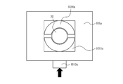
- the fitting members 101a and 101b include buttons 1012a and 1012b, buttons 1013a and 1013b, latch mechanisms 1014a and 1014b, and rubber members 1016a and 1016b.
- the holding member 102X 1 includes convex portions 1021a and 1021b.
- the movable member 106 includes buttons 1061a and 1061b, mounting portions 1062a and 1062b, and buttons 1063.
- the fitting members 101a and 101b are provided so as to be perpendicular to the mounting member 300.
- the fitting member 101a is fitted to one end of the U bolt 20 at the fitting portion 1011a via the rubber member 1016a.
- the fitting member 101b is fitted to the other end of the U bolt 20 at the fitting portion 1011b via the rubber member 1016b.
- the fitting portions 1011a and 1011b are preferably socket-type fitting portions. Thereby, the fitting members 101a and 101b can be fitted to both ends of the U bolt 20 in accordance with the diameters of the various U bolts 20.
- the distance L between the fitting member 101a and the fitting member 101b is arbitrarily adjusted by the movable member 106.
- the interval between the fitting member 101a and the fitting member 101b is, when it is adjusted to the holding member 102X 1 for 100A, the engaging member 101a, the recess 1015a is holding member 102X fitted to one of the convex portion 1021X 1 a, the engaging member 101b, a concave portion 1015b is fitted to the convex portion 1021X 1 b of the holding member 102X 1.
- FIG. 6A the interval between the fitting member 101a and the fitting member 101b is, when it is adjusted to the holding member 102X 1 for 100A, the engaging member 101a, the recess 1015a is holding member 102X fitted to one of the convex portion 1021X 1 a, the engaging member 101b, a concave portion 1015b is fitted to the convex portion 1021X 1 b of the holding member 102X 1.
- the interval between the fitting member 101a and the fitting member 101b is, when it is adjusted to the holding member 102X 2 for 50A, the engaging member 101a, the recess 1015a is holding member 102X fitted into the second protruding portion 1021X 2 a, the engaging member 101b, a concave portion 1015b is fitted to the convex portion 1021X 2 b of the holding member 102X 2.
- Button 1012a, 1012b is a button for attaching the holding member 102X 1 fitting member 101a, to 101b. Operator button 1012a, and press the 1012b, retaining member 102X 1 is fitting member 101a, is secured to 101b.
- fitting member 101a, 101b is provided with a button 1012a, 1012b, the engaging member 101a, but 101b and the holding member 102X 1 can be firmly fixed to the fitting member 101a, 101b is necessarily button 1012a , 1012b may not be provided.
- the buttons 1013a and 1013b are buttons for attaching the U bolt 20 to the fitting portions 1011a and 1011b.
- the rubber members 1016a and 1016b contract, and the U bolt 20 is fixed to the fitting portions 1011a and 1011b (see FIGS. 5A and 5B).
- the buttons 1013a and 1013b When the operator pulls the buttons 1013a and 1013b, the rubber members 1016a and 1016b are extended, and the U bolt 20 is removed from the fitting portions 1011a and 1011b. Since the fitting members 101a and 101b are provided with the buttons 1013a and 1013b, the fitting members 101a and 101b and the U bolt 20 can be firmly fixed.
- the rubber members 1016a and 1016b are provided in the fitting portions 1011a and 1011b, and are arranged between the fitting members 101a and 101b and the U bolt 20. By arranging the rubber members 1016a and 1016b between the fitting members 101a and 101b and the U bolt 20, the fitting members 101a and 101b and the U bolt 20 can be firmly and accurately fixed.
- Latching mechanism 1014a, 1014b when the operator pulls the holding member 102X 1 downward, the holding member 102X 1 is moved downward, when the operator pulls the holding member 102X 1 upward, the holding member 102X It is a mechanism for fixing 1 in the upward direction.
- a plurality of latch mechanisms 1014a and 1014b are provided on the fitting members 101a and 101b at regular intervals. Since the fitting members 101a and 101b are provided with the latch mechanisms 1014a and 1014b, it is possible to prevent the holding member 102X 1 from returning upward even if both hands are released from the holding member 102X 1.
- the operator can fasten the nuts 22a and 22b to the U bolt 20 with both hands via the washers 21a and 21b, so that the workability when attaching the U bolt 20 can be improved. .. After fastening the nuts 22a and 22b, the operator can remove the U-bolt mounting jig 100C from the mounting member 300 by opening the latch mechanisms 1014a and 1014b.
- the holding member 102X 1 is provided so as to be parallel to the mounting member 300.
- the holding member 102X 1 holds the fitting members 101a and 101b so that the straight line D connecting both ends of the U bolt 20 is parallel to the mounting member 300.
- One end of the holding member 102X 1 is joined to the fitting member 101a, and the other end is joined to the fitting member 101b.
- the joining method in which the holding member 102X 1 and the fitting members 101a and 101b are joined is not particularly limited, and is joined by a known method such as bolt joining, welding joining, or adhesive joining. ..
- the operator can appropriately select and use the holding member according to the size of the U bolt 20.
- the nominal dimensions of the U-bolt 20 are, for example, 50A, 80A, 100A, 130A
- the operator can obtain a holding member for 50A, a holding member for 80A, a holding member for 100A, and a holding member for 130A. It is preferable to select and use it as appropriate.
- the operator selects the holding member 102X 1 of "for 100A”.
- the operator selects the holding member 102X 2 of "for 50A".
- the nominal size of the U bolt 20 is described in a position easily visible to the operator (see FIGS. 6A and 6B).
- the holding member 102X 1 of "for 100A”, it has been described as “for 100A” is preferred.
- the holding member 102X 2 for "50A” is described as "for 50A”. Since the nominal size of the U-bolt 20 is described at a position that is easy for the operator to see, the operator can easily determine the holding member that matches the nominal size of the U-bolt 20.
- the movable member 106 is attached to the fitting member 101a and the fitting member 101b.
- the movable member 106 slides in a direction parallel to the mounting member 300 (see the arrows in FIGS. 7A and 7B) to adjust the distance L between the fitting member 101a and the fitting member 101b.
- the movable member 106 is extended, and the distance L between the fitting member 101a and the fitting member 101b becomes long.
- the movable member 106 contracts, and the distance L between the fitting member 101a and the fitting member 101b becomes short.
- the distance L between the fitting member 101a and the fitting member 101b can be appropriately adjusted according to the size of the U bolt 20, the length of the holding member, and the like.
- the operator uses the movable member 106 to set the distance L between the fitting member 101a and the fitting member 101b to be U with a nominal size of 100A. Adjust to fit the size of the bolt 20.
- the convex portion 1021X 1 a holding member 102X 1 is fitted into the concave portion 1015a of the engaging member 101a
- the convex portion 1021X 1 b of the holding member 102X 1 is fitted in the recess 1015b of the fitting member 101b.
- the operator uses the movable member 106 to set the distance L between the fitting member 101a and the fitting member 101b to be U with a nominal size of 50A. Adjust to fit the size of the bolt 20.
- the convex portion 1021X 2 a holding member 102X 2 is fitted into the concave portion 1015a of the engaging member 101a
- the convex portion 1021X 2 b of the holding member 102X 2 is fitted into the recess 1015b of the fitting member 101b.
- the U-bolt mounting jig 100C is not used, to keep insert the holding member 102X 2 of "for 50A" engaging member 101a, and 101b are preferable.
- buttons 1061a and 1061b are buttons for fixing the fitting members 101a and 101b to the movable member 106.
- the fitting member 101a is fixed to the movable member 106
- the button 1061b is fixed to the movable member 106.
- moving member 106 comprises a button 1061a, 1061b, the operator pulling the holding member 102X 1 downward, can be mobile or fixed engagement members 101a, 101b are in the appropriate position.
- the button 1063 is a button for fixing the movable member 106 to the fitting members 101a and 101b.
- the movable member 106 is fixed to the fitting members 101a and 101b.
- the movable member 106 includes the button 1063, the movable member 106 can be arbitrarily slid or fixed in a direction parallel to the mounting member 300.
- the mounting portions 1062a and 1062b fix the movable member 106 to the mounting member 300.
- the mounting portions 1062a and 1062b are preferably embedded inside the movable member 106.
- the mounting portions 1062a and 1062b may be, for example, hooks, magnets, or the like, but the configuration thereof is not particularly limited. Since the movable member 106 includes the mounting portions 1062a and 1062b, the U-bolt mounting jig 100C is fixed to the mounting member 300, so that the operator does not have to perform work such as pressing the movable member 106 by hand. .. As a result, the worker can avoid the inconvenience that both hands are blocked and it is difficult to work. Further, since the operator can fasten the nuts 22a and 22b to the U bolt 20 with both hands via the washers 21a and 21b, the workability when attaching the U bolt 20 can be improved.
- the holding member 102X 1 by pulling downward, the engaging member 101a, but 101b also pulled downwardly, by the movable member 106 is fixed to ⁇ member 300, fitting portions 1011a, 1011b
- the force applied to the mounting portion 1062a, 1062b is balanced with the reaction force at the joint portion between the mounting portions 1062a and 1062b and the mounting member 300.
- the holding member 102X 1 is pulled downward by the operator, the force applied to both ends of the U bolt 20 can be made uniform.
- the operator can mount the U-bolt 20 perpendicularly to the mounting member 300 without increasing the number of parts even in a narrow place. It will be possible.
- the U-bolt mounting jig 100C according to the fourth embodiment can appropriately adjust the distance between the fitting member 101a and the fitting member 101b according to the size of the U-bolt.
- any kind of U-bolt can be attached vertically to the mounting member 300, so that the operator can install the U-bolt without worrying about the size of the U-bolt. It can be carried out.
- step S101 as shown in FIG. 9A, the operator lays the U bolt 20 sideways and installs it on the mounting member 300.
- step S102 as shown in FIG. 9B, the operator sandwiches the pipeline 10 with the U bolt 20 and bolts one end of the U bolt 20 so that the U bolt 20 is perpendicular to the mounting member 300. insert the H 1, inserting the other end of the U-bolt 20 into the bolt holes H 2.
- step S103 as shown in FIG. 9C, the operator U so that the thread length l at one end of the U bolt 20 and the thread length l at the other end of the U bolt 20 are equal. Adjust the positions of both ends of the bolt 20.
- step S104 as shown in FIG. 9D, the operator, from the surface S 2 of the surface S 1 and the opposite side of the ⁇ member 300, via a washer 21a, is temporarily fastened to the nut 22a on one end of the U-bolt 20 .. Further, the operator, from the surface S 2 of the surface S 1 and the opposite side of the ⁇ member 300, via the washer 21b, temporarily fastening the nut 22b to the other end of the U-bolt 20.
- step S105 as shown in FIG. 9E, the operator slides the movable member 106 according to the size of the U bolt 20, adjusts the distance L between the fitting member 101a and the fitting member 101b, and presses the button. Press 1063 to fix the movable member 106 to the fitting members 101a and 101b.
- step S106 as shown in FIG. 9F, the operator, the recess 1015a of the engaging member 101a, fitted with a convex portion 1021X 1 a holding member 102X 1, the recess 1015b of the fitting member 101b, the holding member 102X 1
- the convex portion 1021 X 1 b of the above is fitted.
- step S107 as shown in FIG. 9G, the operator fits the fitting portion 1011a of the fitting member 101a to one end of the U bolt 20, and fits the fitting member 101b to the other end of the U bolt 20.
- the joint portion 1011b is fitted.
- the operator pushes the buttons 1013a and 1013b to crimp the U bolt 20 to the fitting members 101a and 101b and fix it.
- step S108 the operator fixes the movable member 106 to the mounting member 300 via the mounting portions 1062a and 1062b. Then, the operator grips the holding member 102X 1, pulling downward, button 1061a, press 1061b, to secure engagement member 101a, and 101b on the movable member 106. As a result, the U-bolt mounting jig 100C is mounted on the mounting member 300.
- step S109 the operator removes the U-bolt mounting jig 100C from the mounting member 300.
- step S110 as shown in FIG. 9J, the operator finishes the work of attaching the U bolt 20.
- the U bolt 20 is attached to the attachment member 300, and the pipeline 10 is fixed to the attachment member 300.
- the U-bolt mounting method according to the present embodiment includes the above-mentioned steps S101 to S110. As a result, the U bolt 20 can be mounted perpendicularly to the mounting member 300 even in a narrow place without increasing the number of parts.
Landscapes
- Engineering & Computer Science (AREA)
- General Engineering & Computer Science (AREA)
- Mechanical Engineering (AREA)
- Supports For Pipes And Cables (AREA)
- Details Of Spanners, Wrenches, And Screw Drivers And Accessories (AREA)
Priority Applications (3)
| Application Number | Priority Date | Filing Date | Title |
|---|---|---|---|
| PCT/JP2020/025320 WO2021260937A1 (ja) | 2020-06-26 | 2020-06-26 | Uボルト取り付け治具、およびuボルト取り付け方法 |
| US18/012,592 US20230250898A1 (en) | 2020-06-26 | 2020-06-26 | U-bolt mounting device and u-bolt mounting method |
| JP2022532222A JP7425367B2 (ja) | 2020-06-26 | 2020-06-26 | Uボルト取り付け治具、およびuボルト取り付け方法 |
Applications Claiming Priority (1)
| Application Number | Priority Date | Filing Date | Title |
|---|---|---|---|
| PCT/JP2020/025320 WO2021260937A1 (ja) | 2020-06-26 | 2020-06-26 | Uボルト取り付け治具、およびuボルト取り付け方法 |
Publications (1)
| Publication Number | Publication Date |
|---|---|
| WO2021260937A1 true WO2021260937A1 (ja) | 2021-12-30 |
Family
ID=79282135
Family Applications (1)
| Application Number | Title | Priority Date | Filing Date |
|---|---|---|---|
| PCT/JP2020/025320 Ceased WO2021260937A1 (ja) | 2020-06-26 | 2020-06-26 | Uボルト取り付け治具、およびuボルト取り付け方法 |
Country Status (3)
| Country | Link |
|---|---|
| US (1) | US20230250898A1 (https=) |
| JP (1) | JP7425367B2 (https=) |
| WO (1) | WO2021260937A1 (https=) |
Citations (4)
| Publication number | Priority date | Publication date | Assignee | Title |
|---|---|---|---|---|
| JPS4319759Y1 (https=) * | 1965-09-22 | 1968-08-17 | ||
| JPS5943705U (ja) * | 1982-09-14 | 1984-03-22 | カルソニックカンセイ株式会社 | クランプ金具 |
| JPS5968886U (ja) * | 1982-10-30 | 1984-05-10 | 陽和産業株式会社 | パイプ支持具 |
| JPS59127982U (ja) * | 1983-02-17 | 1984-08-28 | 東芝プラント建設株式会社 | 配管支持用uボルト |
Family Cites Families (10)
| Publication number | Priority date | Publication date | Assignee | Title |
|---|---|---|---|---|
| US648501A (en) * | 1899-10-12 | 1900-05-01 | Carl Jul Kronenberg | Apparatus for supporting overground wires. |
| US4320882A (en) * | 1978-03-29 | 1982-03-23 | General Signal Corporation | Clamp for grounding and clamping a conduit to a support member |
| US4180228A (en) * | 1978-03-29 | 1979-12-25 | Pullman Incorporated | Pipe clamp |
| ZA784951B (en) * | 1978-08-30 | 1980-04-30 | N Milner | Fastener |
| US4355979A (en) * | 1979-08-27 | 1982-10-26 | Ipco Corporation | Lingual dental splint device |
| US4397437A (en) * | 1980-07-21 | 1983-08-09 | Robroy Industries | Beam clamp |
| FI76875C (sv) * | 1986-07-25 | 1988-12-12 | Goeran Sundholm | Rörklammer. |
| US5718403A (en) * | 1994-04-12 | 1998-02-17 | Deere & Company | Mounting hardware for a toolbar |
| JPH09296881A (ja) * | 1996-05-02 | 1997-11-18 | Kii Seisan Kk | 電気絶縁uボルトの電気絶縁管被着方法、並びに、電気絶縁uボルト |
| US9416895B2 (en) * | 2013-11-26 | 2016-08-16 | Jose Oscar Castellanos | Attachment system for supporting a pipe |
-
2020
- 2020-06-26 US US18/012,592 patent/US20230250898A1/en not_active Abandoned
- 2020-06-26 WO PCT/JP2020/025320 patent/WO2021260937A1/ja not_active Ceased
- 2020-06-26 JP JP2022532222A patent/JP7425367B2/ja active Active
Patent Citations (4)
| Publication number | Priority date | Publication date | Assignee | Title |
|---|---|---|---|---|
| JPS4319759Y1 (https=) * | 1965-09-22 | 1968-08-17 | ||
| JPS5943705U (ja) * | 1982-09-14 | 1984-03-22 | カルソニックカンセイ株式会社 | クランプ金具 |
| JPS5968886U (ja) * | 1982-10-30 | 1984-05-10 | 陽和産業株式会社 | パイプ支持具 |
| JPS59127982U (ja) * | 1983-02-17 | 1984-08-28 | 東芝プラント建設株式会社 | 配管支持用uボルト |
Also Published As
| Publication number | Publication date |
|---|---|
| US20230250898A1 (en) | 2023-08-10 |
| JP7425367B2 (ja) | 2024-01-31 |
| JPWO2021260937A1 (https=) | 2021-12-30 |
Similar Documents
| Publication | Publication Date | Title |
|---|---|---|
| US8038106B2 (en) | Fast beam clamp | |
| US20100032535A1 (en) | Clamping Device | |
| US6710235B2 (en) | Electric guitar with tremolo unit | |
| WO2021260937A1 (ja) | Uボルト取り付け治具、およびuボルト取り付け方法 | |
| US11187353B1 (en) | Strut channel mounting clip | |
| JP5041365B2 (ja) | 屋外通信装置の設置構造及び設置方法 | |
| GB2457711A (en) | Tension device | |
| JP4093560B2 (ja) | 親綱支柱 | |
| US8353381B2 (en) | Transmission cross-member | |
| JP7324981B2 (ja) | Uボルト取り付け治具、およびuボルト取り付け方法 | |
| US7712731B2 (en) | Gutter clamp | |
| JP2002188757A (ja) | ケーブル類架設具 | |
| JP2005321065A (ja) | 一般形鋼用支持金具 | |
| JP3216172U (ja) | アンテナ設置補助装置 | |
| CN212510163U (zh) | 一种支臂 | |
| CN223895298U (zh) | 一种工程施工用集成式管道吊架 | |
| CN218529578U (zh) | 一种型材挂点安装组件及悬挂装置 | |
| CN214396647U (zh) | 车辆及其管线支架 | |
| JP2017189055A (ja) | 分線金物留め具 | |
| JP3917696B2 (ja) | 建物の屋上等に設置される照明器具等の支持具 | |
| JP3114219U (ja) | 手動運搬車の補強具およびそれを装着した手動運搬車 | |
| US20100282938A1 (en) | Mounting bracket for support post of fitness apparatus | |
| JP3084153U (ja) | コンクリート柱補強機構 | |
| CN121711917A (zh) | 逆变器固定装置 | |
| JP2020156240A (ja) | ケーブル敷設補助具およびケーブル敷設補助具設置方法 |
Legal Events
| Date | Code | Title | Description |
|---|---|---|---|
| 121 | Ep: the epo has been informed by wipo that ep was designated in this application |
Ref document number: 20942096 Country of ref document: EP Kind code of ref document: A1 |
|
| ENP | Entry into the national phase |
Ref document number: 2022532222 Country of ref document: JP Kind code of ref document: A |
|
| NENP | Non-entry into the national phase |
Ref country code: DE |
|
| 122 | Ep: pct application non-entry in european phase |
Ref document number: 20942096 Country of ref document: EP Kind code of ref document: A1 |