WO2021260937A1 - U-bolt attachment jig and u-bolt attachment method - Google Patents
U-bolt attachment jig and u-bolt attachment method Download PDFInfo
- Publication number
- WO2021260937A1 WO2021260937A1 PCT/JP2020/025320 JP2020025320W WO2021260937A1 WO 2021260937 A1 WO2021260937 A1 WO 2021260937A1 JP 2020025320 W JP2020025320 W JP 2020025320W WO 2021260937 A1 WO2021260937 A1 WO 2021260937A1
- Authority
- WO
- WIPO (PCT)
- Prior art keywords
- bolt
- mounting
- fitting
- operator
- holding
- Prior art date
Links
- 238000000034 method Methods 0.000 title claims description 36
- 230000000149 penetrating effect Effects 0.000 claims description 12
- 230000013011 mating Effects 0.000 claims 1
- 238000009434 installation Methods 0.000 abstract description 4
- 230000007246 mechanism Effects 0.000 description 7
- 229910000831 Steel Inorganic materials 0.000 description 5
- 239000010959 steel Substances 0.000 description 5
- 239000000853 adhesive Substances 0.000 description 3
- 230000001070 adhesive effect Effects 0.000 description 3
- 239000002184 metal Substances 0.000 description 3
- 230000001681 protective effect Effects 0.000 description 3
- 229920002430 Fibre-reinforced plastic Polymers 0.000 description 2
- 239000011151 fibre-reinforced plastic Substances 0.000 description 2
- 238000012986 modification Methods 0.000 description 2
- 230000004048 modification Effects 0.000 description 2
- 238000003466 welding Methods 0.000 description 2
- 238000006243 chemical reaction Methods 0.000 description 1
- 239000011152 fibreglass Substances 0.000 description 1
- 238000012423 maintenance Methods 0.000 description 1
- 239000000463 material Substances 0.000 description 1
- 239000004570 mortar (masonry) Substances 0.000 description 1
- 238000003825 pressing Methods 0.000 description 1
- 239000011347 resin Substances 0.000 description 1
- 229920005989 resin Polymers 0.000 description 1
- 238000006467 substitution reaction Methods 0.000 description 1
- 125000000391 vinyl group Chemical group [H]C([*])=C([H])[H] 0.000 description 1
- 229920002554 vinyl polymer Polymers 0.000 description 1
Images


Classifications
-
- B—PERFORMING OPERATIONS; TRANSPORTING
- B25—HAND TOOLS; PORTABLE POWER-DRIVEN TOOLS; MANIPULATORS
- B25H—WORKSHOP EQUIPMENT, e.g. FOR MARKING-OUT WORK; STORAGE MEANS FOR WORKSHOPS
- B25H7/00—Marking-out or setting-out work
- B25H7/02—Plates having a flat surface
-
- B—PERFORMING OPERATIONS; TRANSPORTING
- B25—HAND TOOLS; PORTABLE POWER-DRIVEN TOOLS; MANIPULATORS
- B25B—TOOLS OR BENCH DEVICES NOT OTHERWISE PROVIDED FOR, FOR FASTENING, CONNECTING, DISENGAGING OR HOLDING
- B25B23/00—Details of, or accessories for, spanners, wrenches, screwdrivers
- B25B23/02—Arrangements for handling screws or nuts
- B25B23/08—Arrangements for handling screws or nuts for holding or positioning screw or nut prior to or during its rotation
- B25B23/10—Arrangements for handling screws or nuts for holding or positioning screw or nut prior to or during its rotation using mechanical gripping means
-
- F—MECHANICAL ENGINEERING; LIGHTING; HEATING; WEAPONS; BLASTING
- F16—ENGINEERING ELEMENTS AND UNITS; GENERAL MEASURES FOR PRODUCING AND MAINTAINING EFFECTIVE FUNCTIONING OF MACHINES OR INSTALLATIONS; THERMAL INSULATION IN GENERAL
- F16L—PIPES; JOINTS OR FITTINGS FOR PIPES; SUPPORTS FOR PIPES, CABLES OR PROTECTIVE TUBING; MEANS FOR THERMAL INSULATION IN GENERAL
- F16L1/00—Laying or reclaiming pipes; Repairing or joining pipes on or under water
- F16L1/024—Laying or reclaiming pipes on land, e.g. above the ground
- F16L1/06—Accessories therefor, e.g. anchors
-
- F—MECHANICAL ENGINEERING; LIGHTING; HEATING; WEAPONS; BLASTING
- F16—ENGINEERING ELEMENTS AND UNITS; GENERAL MEASURES FOR PRODUCING AND MAINTAINING EFFECTIVE FUNCTIONING OF MACHINES OR INSTALLATIONS; THERMAL INSULATION IN GENERAL
- F16L—PIPES; JOINTS OR FITTINGS FOR PIPES; SUPPORTS FOR PIPES, CABLES OR PROTECTIVE TUBING; MEANS FOR THERMAL INSULATION IN GENERAL
- F16L3/00—Supports for pipes, cables or protective tubing, e.g. hangers, holders, clamps, cleats, clips, brackets
- F16L3/02—Supports for pipes, cables or protective tubing, e.g. hangers, holders, clamps, cleats, clips, brackets partly surrounding the pipes, cables or protective tubing
- F16L3/04—Supports for pipes, cables or protective tubing, e.g. hangers, holders, clamps, cleats, clips, brackets partly surrounding the pipes, cables or protective tubing and pressing it against a wall or other support
-
- F—MECHANICAL ENGINEERING; LIGHTING; HEATING; WEAPONS; BLASTING
- F16—ENGINEERING ELEMENTS AND UNITS; GENERAL MEASURES FOR PRODUCING AND MAINTAINING EFFECTIVE FUNCTIONING OF MACHINES OR INSTALLATIONS; THERMAL INSULATION IN GENERAL
- F16L—PIPES; JOINTS OR FITTINGS FOR PIPES; SUPPORTS FOR PIPES, CABLES OR PROTECTIVE TUBING; MEANS FOR THERMAL INSULATION IN GENERAL
- F16L3/00—Supports for pipes, cables or protective tubing, e.g. hangers, holders, clamps, cleats, clips, brackets
- F16L3/08—Supports for pipes, cables or protective tubing, e.g. hangers, holders, clamps, cleats, clips, brackets substantially surrounding the pipe, cable or protective tubing
- F16L3/12—Supports for pipes, cables or protective tubing, e.g. hangers, holders, clamps, cleats, clips, brackets substantially surrounding the pipe, cable or protective tubing comprising a member substantially surrounding the pipe, cable or protective tubing
- F16L3/1207—Supports for pipes, cables or protective tubing, e.g. hangers, holders, clamps, cleats, clips, brackets substantially surrounding the pipe, cable or protective tubing comprising a member substantially surrounding the pipe, cable or protective tubing the ends of the member and the fixing elements being placed on both sides of the pipe
Definitions
- This disclosure relates to a U-bolt mounting jig and a U-bolt mounting method.
- Patent Document 1 includes a U-bolt for fixing a pipe to a frame, a first support portion for supporting the pipe, and a saddle including a second support portion arranged between the pipe and the frame.
- a U-bolt structure that improves support rigidity and load capacity and allows fine adjustment of the saddle is disclosed.
- Non-Patent Document 1 discloses details of the size of the U-bolt 20.
- the bolt hole into which the U bolt is inserted is formed so as to be larger than the diameter of the U bolt.
- a U-bolt having a diameter of 9 mm as shown in FIG. 10B is inserted into a bolt hole having a length of 30 mm in the longitudinal direction and a length of 15 mm in the lateral direction as shown in FIG. 10A.
- An extra space of 10.5 mm is formed at both ends of the U bolt in the longitudinal direction, and 3 mm is formed at both ends of the U bolt in the lateral direction.
- the object of the present disclosure made in view of such circumstances is a U-bolt mounting jig and a U-bolt mounting jig that can mount a U-bolt vertically to a mounting member without increasing the number of parts even in a narrow place. To provide a bolt mounting method.
- the U-bolt mounting jig is a U-bolt mounting jig for mounting a U-bolt for fixing a pipeline to a mounting member, and the U-bolt inserted into a bolt hole provided in the mounting member.
- the first fitting member and the second fitting so that the straight line connecting the first fitting member and the second fitting member to be fitted to both ends of the bolt is parallel to the mounting member. It is characterized by including a holding member for holding the combined member.
- the U-bolt mounting method is a U-bolt mounting method for mounting a U-bolt for fixing a pipeline to a mounting member, and both ends of the U-bolt are provided in bolt holes provided in the mounting member.
- the step of inserting, the step of temporarily fastening the nut to the U bolt, the first fitting member and the second fitting member that are fitted to the both ends, and the straight line connecting the both ends are attached to the mounting member.
- a U-bolt mounting jig capable of mounting a U-bolt vertically to a mounting member without increasing the number of parts even in a narrow place, and a U-bolt mounting method. Can be done.
- the U-bolt is perpendicular to the mounting member
- the side portions of the U-bolt are arranged closer to the mounting member than the central portion of the U-bolt, and both ends of the U-bolt are designated. It is assumed that the straight line to be connected is parallel to the surface of the mounting member (at this time, the straight line portion of the U-bolt end is perpendicular to the mounting member).
- the U-bolt is slanted with respect to the mounting member means that the straight line connecting both ends of the U-bolt is tilted with respect to the surface of the mounting member.
- upward means a positive direction parallel to the Z axis of the coordinate axis display drawn in the drawing
- downward means the coordinate axis display drawn in the drawing. It shall mean a negative direction parallel to the Z axis of.
- the U-bolt attachment jig 100 is a jig for attaching the U-bolt 20 for fixing the pipeline 10 to the attachment member 300 attached to a structure such as a bridge.
- ⁇ member 300 is the surface S 1 is a plane, the conduit 10 may have a stable and capable of supporting a configuration.
- the supporting member 300 is made of, for example, L-shaped steel, flat steel, H-shaped steel, or the like.
- the ⁇ member 300, the bolt hole H 2 is provided with the other end of the bolt holes H 1 and U-bolts 20 one end of U-bolt 20 is inserted is inserted.
- the pipeline 10 is a resin or metal pipe, for example, a hard vinyl pipe, an FRP (Fiber Reinforced Plastics) pipe, a steel pipe, a FRPM (Fiberglass Reinforced Plastic Mortar) pipe, or the like.
- the pipeline 10 may have a cylindrical shape, and its configuration is not particularly limited.
- the pipeline 10 may be provided with a joint or the like and may have irregularities on the outside.
- the pipeline 10 may be provided with a protective piece 11 bonded with an adhesive to the outside (see FIG. 1).
- the pipeline 10 can be protected when the pipeline 10 is fixed to the mounting member 300 by the U bolt 20.
- FIG. 1 cites a case where one pipeline 10 is installed in the auxiliary member 300 as an example, but the number of pipelines 10 installed in the auxiliary member 300 is not particularly limited.
- the U-bolt 20 is a single steel material having a curved central portion, a linear shape at the side portions, and a bolt structure at both ends. U-bolt 20, both ends, is inserted into the bolt holes H 1 and bolt holes H 2, line 10, ⁇ member 300, and washers 21a, via 21b, nuts 22a, to 22b and screwed. As a result, the pipeline 10 is fixed to the attachment member 300.
- the U-bolt mounting jig 100 includes a fitting member (first fitting member) 101a, a fitting member (second fitting member) 101b, and a holding member 102.
- the fitting member 101a is provided with a fitting portion 1011a.
- the fitting member 101b is provided with a fitting portion 1011b.
- the fitting members 101a and 101b are provided so as to be perpendicular to the mounting member 300.
- the fitting member 101a fits with one end of the U bolt 20 at the fitting portion 1011a
- the fitting member 101b fits with the other end of the U bolt 20 at the fitting portion 1011b.
- the distance L between the fitting member 101a and the fitting member 101b is set based on the size of the U bolt 20 (JIS standard). The operator appropriately selects and uses the U-bolt mounting jig 100 suitable for the size of the U-bolt 20.
- the holding member 102 is provided so as to be parallel to the mounting member 300.
- the holding member 102 holds the fitting members 101a and 101b so that the straight line D connecting both ends of the U bolt 20 is parallel to the mounting member 300.
- the holding member 102 is held in parallel with the mounting member 300, so that the straight line D connecting both ends of the U bolt 20 is connected to the mounting member. It can be parallel to 300.
- One end of the holding member 102 is joined to the fitting member 101a, and the other end is joined to the fitting member 101b.
- the joining method for joining the holding member 102 and the fitting members 101a and 101b is not particularly limited, and for example, bolt joining, welding joining, adhesive joining, or the like is used for joining.
- the operator attaches the U-bolt 20 perpendicularly to the mounting member 300 by fastening the nuts 22a and 22b to the U-bolt 20 via the washers 21a and 21b while pulling the holding member 102 downward. It becomes possible.
- the fitting members 101a and 101b that are fitted to both ends of the U-bolt 20 and the straight line D connecting both ends of the U-bolt 20 have a straight line D with respect to the mounting member 300.
- a holding member 102 for holding the fitting members 101a and 101b is provided so as to be parallel to each other.
- the worker lays the U bolt 20 on its side and installs it on the mounting member 300 (see FIG. 9A).
- the operator positions both ends of the U-bolt 20 so that the thread length l at one end of the U-bolt 20 and the thread length l at the other end of the U-bolt 20 are equal. Adjust (see FIG. 9C).
- the operator from the surface S 2 of the surface S 1 and the opposite side of the ⁇ member 300, via a washer 21a, is temporarily fastened to the nut 22a on one end of the U-bolt 20. Further, the operator, from the surface S 2 of the surface S 1 and the opposite side of the ⁇ member 300, via the washer 21b, temporarily fastening the nut 22b to the other end of the U-bolt 20 (see FIG. 9D).
- the operator attaches the U-bolt mounting jig 100 according to the first embodiment to the U-bolt 20 (see FIG. 1).
- the operator grips the holding member 102, while pulling downward, from the face S 2 of the surface S 1 and the opposite side of the ⁇ member 300, via a washer 21a, at one end of the U-bolt 20 concluded nuts 22a, from the surface S 1 and the opposite surface S 2 of ⁇ member 300, via the washer 21b, fastening a nut 22b to the other end of the U-bolt 20.
- the operator removes the U-bolt mounting jig 100 from the U-bolt 20, and completes the mounting work of the U-bolt 20.
- the U bolt 20 is attached to the attachment member 300, and the pipeline 10 is fixed to the attachment member 300.
- the U-bolt mounting method according to the first embodiment makes it possible to mount the U-bolt 20 vertically to the attachment member 300 without increasing the number of parts, even in a narrow place.
- the difference between the U-bolt mounting jig 100A according to the second embodiment and the U-bolt mounting jig 100 according to the first embodiment is that the U-bolt mounting jig 100 according to the first embodiment does not include a gripping member.
- the U-bolt mounting jig 100A according to the second embodiment is provided with a gripping member. Since the other configurations are the same as those of the U-bolt mounting jig 100 according to the first embodiment, duplicated description will be omitted.
- the grip member 103 is attached to the central portion of the holding member 102.
- the gripping member 103 preferably has a shape that is easy for an operator to grip by hand, and is composed of, for example, a rod-shaped member.
- the operator can mount the U-bolt 20 perpendicularly to the mounting member 300 without increasing the number of parts even in a narrow place. It will be possible.
- the worker lays the U bolt 20 on its side and installs it on the mounting member 300 (see FIG. 9A).
- the operator positions both ends of the U-bolt 20 so that the thread length l at one end of the U-bolt 20 and the thread length l at the other end of the U-bolt 20 are equal. Adjust (see FIG. 9C).
- the operator from the surface S 2 of the surface S 1 and the opposite side of the ⁇ member 300, via a washer 21a, is temporarily fastened to the nut 22a on one end of the U-bolt 20. Further, the operator, from the surface S 2 of the surface S 1 and the opposite side of the ⁇ member 300, via the washer 21b, temporarily fastening the nut 22b to the other end of the U-bolt 20 (see FIG. 9D).
- the operator attaches the U-bolt attachment jig 100A according to the second embodiment to the U-bolt 20 (see FIG. 2).
- the operator grips the grip member 103, while pulling downward, from the face S 2 of the surface S 1 and the opposite side of the ⁇ member 300, via a washer 21a, at one end of the U-bolt 20 concluded nuts 22a, from the surface S 1 and the opposite surface S 2 of ⁇ member 300, via the washer 21b, fastening a nut 22b to the other end of the U-bolt 20.
- the operator removes the U-bolt mounting jig 100A from the U-bolt 20, and completes the mounting work of the U-bolt 20.
- the U bolt 20 is attached to the attachment member 300, and the pipeline 10 is fixed to the attachment member 300.
- the U-bolt mounting method according to the second embodiment makes it possible to mount the U-bolt 20 vertically to the attachment member 300 without increasing the number of parts, even in a narrow place.
- the U-bolt mounting jig 100B according to the third embodiment is different from the U-bolt mounting jig 100 according to the first embodiment in that the U-bolt mounting jig 100 according to the first embodiment is a penetrating member and a fixing member. However, the U-bolt mounting jig 100B according to the third embodiment is provided with a penetrating member and a fixing member. Since the other configurations are the same as those of the U-bolt mounting jig 100 according to the first embodiment, duplicated description will be omitted.
- the penetrating member 104 is provided so as to be parallel to the mounting member 300.
- the penetrating member 104 penetrates the fitting members 101a and 101b so as to be parallel to the mounting member 300 (see FIG. 3B).
- the fixing member 105 is joined to the penetrating member 104.
- the fixing member 105 is fixed to the mounting member 300 so that the distance between the penetrating member 104 and the mounting member 300 is constant.
- the distance between the penetrating member 104 and the mounting member 300 is kept constant, so that when the holding member 102 is pulled downward by the operator, it is applied to both ends of the U bolt 20.
- the force can be made uniform.
- the straight line D connecting both ends of the U-bolt 20 tends to be parallel to the mounting member 300, so that the operator can easily attach the U-bolt 20 perpendicular to the mounting member 300. Will be.
- the operator can take the U-bolt 20 perpendicularly to the mounting member 300 without increasing the number of parts even in a narrow place.
- the worker lays the U bolt 20 on its side and installs it on the mounting member 300 (see FIG. 9A).
- the operator positions both ends of the U-bolt 20 so that the thread length l at one end of the U-bolt 20 and the thread length l at the other end of the U-bolt 20 are equal. Adjust (see FIG. 9C).
- the operator from the surface S 2 of the surface S 1 and the opposite side of the ⁇ member 300, via a washer 21a, is temporarily fastened to the nut 22a on one end of the U-bolt 20. Further, the operator, from the surface S 2 of the surface S 1 and the opposite side of the ⁇ member 300, via the washer 21b, temporarily fastening the nut 22b to the other end of the U-bolt 20 (see FIG. 9D).
- the operator attaches the U-bolt mounting jig 100B according to the third embodiment to the U-bolt 20 (see FIG. 3A).
- the operator grips the holding member 102, while pulling downward, from the face S 2 of the surface S 1 and the opposite side of the ⁇ member 300, via a washer 21a, at one end of the U-bolt 20 concluded nuts 22a, from the surface S 1 and the opposite surface S 2 of ⁇ member 300, via the washer 21b, fastening a nut 22b to the other end of the U-bolt 20.
- the operator removes the U-bolt mounting jig 100B from the U-bolt 20, and completes the mounting work of the U-bolt 20.
- the U bolt 20 is attached to the attachment member 300, and the pipeline 10 is fixed to the attachment member 300.
- the U-bolt mounting method according to the third embodiment makes it possible to mount the U-bolt 20 vertically to the mounting member 300 without increasing the number of parts, even in a narrow place. It becomes possible to attach.
- U bolt fixture 100C includes engaging members 101a, and 101b, and the holding member 102X 1, a movable member 106, a.
- Fitting member 101a is fitted portion 1011a is provided in the U-bolt 20, the recess 1015a is provided in the holding member 102X 1 side.
- Fitting member 101b is fitted portion 1011b is provided on the U-bolt 20, the recess 1015b is provided in the holding member 102X 1 side.
- the fitting members 101a and 101b include buttons 1012a and 1012b, buttons 1013a and 1013b, latch mechanisms 1014a and 1014b, and rubber members 1016a and 1016b.
- the holding member 102X 1 includes convex portions 1021a and 1021b.
- the movable member 106 includes buttons 1061a and 1061b, mounting portions 1062a and 1062b, and buttons 1063.
- the fitting members 101a and 101b are provided so as to be perpendicular to the mounting member 300.
- the fitting member 101a is fitted to one end of the U bolt 20 at the fitting portion 1011a via the rubber member 1016a.
- the fitting member 101b is fitted to the other end of the U bolt 20 at the fitting portion 1011b via the rubber member 1016b.
- the fitting portions 1011a and 1011b are preferably socket-type fitting portions. Thereby, the fitting members 101a and 101b can be fitted to both ends of the U bolt 20 in accordance with the diameters of the various U bolts 20.
- the distance L between the fitting member 101a and the fitting member 101b is arbitrarily adjusted by the movable member 106.
- the interval between the fitting member 101a and the fitting member 101b is, when it is adjusted to the holding member 102X 1 for 100A, the engaging member 101a, the recess 1015a is holding member 102X fitted to one of the convex portion 1021X 1 a, the engaging member 101b, a concave portion 1015b is fitted to the convex portion 1021X 1 b of the holding member 102X 1.
- FIG. 6A the interval between the fitting member 101a and the fitting member 101b is, when it is adjusted to the holding member 102X 1 for 100A, the engaging member 101a, the recess 1015a is holding member 102X fitted to one of the convex portion 1021X 1 a, the engaging member 101b, a concave portion 1015b is fitted to the convex portion 1021X 1 b of the holding member 102X 1.
- the interval between the fitting member 101a and the fitting member 101b is, when it is adjusted to the holding member 102X 2 for 50A, the engaging member 101a, the recess 1015a is holding member 102X fitted into the second protruding portion 1021X 2 a, the engaging member 101b, a concave portion 1015b is fitted to the convex portion 1021X 2 b of the holding member 102X 2.
- Button 1012a, 1012b is a button for attaching the holding member 102X 1 fitting member 101a, to 101b. Operator button 1012a, and press the 1012b, retaining member 102X 1 is fitting member 101a, is secured to 101b.
- fitting member 101a, 101b is provided with a button 1012a, 1012b, the engaging member 101a, but 101b and the holding member 102X 1 can be firmly fixed to the fitting member 101a, 101b is necessarily button 1012a , 1012b may not be provided.
- the buttons 1013a and 1013b are buttons for attaching the U bolt 20 to the fitting portions 1011a and 1011b.
- the rubber members 1016a and 1016b contract, and the U bolt 20 is fixed to the fitting portions 1011a and 1011b (see FIGS. 5A and 5B).
- the buttons 1013a and 1013b When the operator pulls the buttons 1013a and 1013b, the rubber members 1016a and 1016b are extended, and the U bolt 20 is removed from the fitting portions 1011a and 1011b. Since the fitting members 101a and 101b are provided with the buttons 1013a and 1013b, the fitting members 101a and 101b and the U bolt 20 can be firmly fixed.
- the rubber members 1016a and 1016b are provided in the fitting portions 1011a and 1011b, and are arranged between the fitting members 101a and 101b and the U bolt 20. By arranging the rubber members 1016a and 1016b between the fitting members 101a and 101b and the U bolt 20, the fitting members 101a and 101b and the U bolt 20 can be firmly and accurately fixed.
- Latching mechanism 1014a, 1014b when the operator pulls the holding member 102X 1 downward, the holding member 102X 1 is moved downward, when the operator pulls the holding member 102X 1 upward, the holding member 102X It is a mechanism for fixing 1 in the upward direction.
- a plurality of latch mechanisms 1014a and 1014b are provided on the fitting members 101a and 101b at regular intervals. Since the fitting members 101a and 101b are provided with the latch mechanisms 1014a and 1014b, it is possible to prevent the holding member 102X 1 from returning upward even if both hands are released from the holding member 102X 1.
- the operator can fasten the nuts 22a and 22b to the U bolt 20 with both hands via the washers 21a and 21b, so that the workability when attaching the U bolt 20 can be improved. .. After fastening the nuts 22a and 22b, the operator can remove the U-bolt mounting jig 100C from the mounting member 300 by opening the latch mechanisms 1014a and 1014b.
- the holding member 102X 1 is provided so as to be parallel to the mounting member 300.
- the holding member 102X 1 holds the fitting members 101a and 101b so that the straight line D connecting both ends of the U bolt 20 is parallel to the mounting member 300.
- One end of the holding member 102X 1 is joined to the fitting member 101a, and the other end is joined to the fitting member 101b.
- the joining method in which the holding member 102X 1 and the fitting members 101a and 101b are joined is not particularly limited, and is joined by a known method such as bolt joining, welding joining, or adhesive joining. ..
- the operator can appropriately select and use the holding member according to the size of the U bolt 20.
- the nominal dimensions of the U-bolt 20 are, for example, 50A, 80A, 100A, 130A
- the operator can obtain a holding member for 50A, a holding member for 80A, a holding member for 100A, and a holding member for 130A. It is preferable to select and use it as appropriate.
- the operator selects the holding member 102X 1 of "for 100A”.
- the operator selects the holding member 102X 2 of "for 50A".
- the nominal size of the U bolt 20 is described in a position easily visible to the operator (see FIGS. 6A and 6B).
- the holding member 102X 1 of "for 100A”, it has been described as “for 100A” is preferred.
- the holding member 102X 2 for "50A” is described as "for 50A”. Since the nominal size of the U-bolt 20 is described at a position that is easy for the operator to see, the operator can easily determine the holding member that matches the nominal size of the U-bolt 20.
- the movable member 106 is attached to the fitting member 101a and the fitting member 101b.
- the movable member 106 slides in a direction parallel to the mounting member 300 (see the arrows in FIGS. 7A and 7B) to adjust the distance L between the fitting member 101a and the fitting member 101b.
- the movable member 106 is extended, and the distance L between the fitting member 101a and the fitting member 101b becomes long.
- the movable member 106 contracts, and the distance L between the fitting member 101a and the fitting member 101b becomes short.
- the distance L between the fitting member 101a and the fitting member 101b can be appropriately adjusted according to the size of the U bolt 20, the length of the holding member, and the like.
- the operator uses the movable member 106 to set the distance L between the fitting member 101a and the fitting member 101b to be U with a nominal size of 100A. Adjust to fit the size of the bolt 20.
- the convex portion 1021X 1 a holding member 102X 1 is fitted into the concave portion 1015a of the engaging member 101a
- the convex portion 1021X 1 b of the holding member 102X 1 is fitted in the recess 1015b of the fitting member 101b.
- the operator uses the movable member 106 to set the distance L between the fitting member 101a and the fitting member 101b to be U with a nominal size of 50A. Adjust to fit the size of the bolt 20.
- the convex portion 1021X 2 a holding member 102X 2 is fitted into the concave portion 1015a of the engaging member 101a
- the convex portion 1021X 2 b of the holding member 102X 2 is fitted into the recess 1015b of the fitting member 101b.
- the U-bolt mounting jig 100C is not used, to keep insert the holding member 102X 2 of "for 50A" engaging member 101a, and 101b are preferable.
- buttons 1061a and 1061b are buttons for fixing the fitting members 101a and 101b to the movable member 106.
- the fitting member 101a is fixed to the movable member 106
- the button 1061b is fixed to the movable member 106.
- moving member 106 comprises a button 1061a, 1061b, the operator pulling the holding member 102X 1 downward, can be mobile or fixed engagement members 101a, 101b are in the appropriate position.
- the button 1063 is a button for fixing the movable member 106 to the fitting members 101a and 101b.
- the movable member 106 is fixed to the fitting members 101a and 101b.
- the movable member 106 includes the button 1063, the movable member 106 can be arbitrarily slid or fixed in a direction parallel to the mounting member 300.
- the mounting portions 1062a and 1062b fix the movable member 106 to the mounting member 300.
- the mounting portions 1062a and 1062b are preferably embedded inside the movable member 106.
- the mounting portions 1062a and 1062b may be, for example, hooks, magnets, or the like, but the configuration thereof is not particularly limited. Since the movable member 106 includes the mounting portions 1062a and 1062b, the U-bolt mounting jig 100C is fixed to the mounting member 300, so that the operator does not have to perform work such as pressing the movable member 106 by hand. .. As a result, the worker can avoid the inconvenience that both hands are blocked and it is difficult to work. Further, since the operator can fasten the nuts 22a and 22b to the U bolt 20 with both hands via the washers 21a and 21b, the workability when attaching the U bolt 20 can be improved.
- the holding member 102X 1 by pulling downward, the engaging member 101a, but 101b also pulled downwardly, by the movable member 106 is fixed to ⁇ member 300, fitting portions 1011a, 1011b
- the force applied to the mounting portion 1062a, 1062b is balanced with the reaction force at the joint portion between the mounting portions 1062a and 1062b and the mounting member 300.
- the holding member 102X 1 is pulled downward by the operator, the force applied to both ends of the U bolt 20 can be made uniform.
- the operator can mount the U-bolt 20 perpendicularly to the mounting member 300 without increasing the number of parts even in a narrow place. It will be possible.
- the U-bolt mounting jig 100C according to the fourth embodiment can appropriately adjust the distance between the fitting member 101a and the fitting member 101b according to the size of the U-bolt.
- any kind of U-bolt can be attached vertically to the mounting member 300, so that the operator can install the U-bolt without worrying about the size of the U-bolt. It can be carried out.
- step S101 as shown in FIG. 9A, the operator lays the U bolt 20 sideways and installs it on the mounting member 300.
- step S102 as shown in FIG. 9B, the operator sandwiches the pipeline 10 with the U bolt 20 and bolts one end of the U bolt 20 so that the U bolt 20 is perpendicular to the mounting member 300. insert the H 1, inserting the other end of the U-bolt 20 into the bolt holes H 2.
- step S103 as shown in FIG. 9C, the operator U so that the thread length l at one end of the U bolt 20 and the thread length l at the other end of the U bolt 20 are equal. Adjust the positions of both ends of the bolt 20.
- step S104 as shown in FIG. 9D, the operator, from the surface S 2 of the surface S 1 and the opposite side of the ⁇ member 300, via a washer 21a, is temporarily fastened to the nut 22a on one end of the U-bolt 20 .. Further, the operator, from the surface S 2 of the surface S 1 and the opposite side of the ⁇ member 300, via the washer 21b, temporarily fastening the nut 22b to the other end of the U-bolt 20.
- step S105 as shown in FIG. 9E, the operator slides the movable member 106 according to the size of the U bolt 20, adjusts the distance L between the fitting member 101a and the fitting member 101b, and presses the button. Press 1063 to fix the movable member 106 to the fitting members 101a and 101b.
- step S106 as shown in FIG. 9F, the operator, the recess 1015a of the engaging member 101a, fitted with a convex portion 1021X 1 a holding member 102X 1, the recess 1015b of the fitting member 101b, the holding member 102X 1
- the convex portion 1021 X 1 b of the above is fitted.
- step S107 as shown in FIG. 9G, the operator fits the fitting portion 1011a of the fitting member 101a to one end of the U bolt 20, and fits the fitting member 101b to the other end of the U bolt 20.
- the joint portion 1011b is fitted.
- the operator pushes the buttons 1013a and 1013b to crimp the U bolt 20 to the fitting members 101a and 101b and fix it.
- step S108 the operator fixes the movable member 106 to the mounting member 300 via the mounting portions 1062a and 1062b. Then, the operator grips the holding member 102X 1, pulling downward, button 1061a, press 1061b, to secure engagement member 101a, and 101b on the movable member 106. As a result, the U-bolt mounting jig 100C is mounted on the mounting member 300.
- step S109 the operator removes the U-bolt mounting jig 100C from the mounting member 300.
- step S110 as shown in FIG. 9J, the operator finishes the work of attaching the U bolt 20.
- the U bolt 20 is attached to the attachment member 300, and the pipeline 10 is fixed to the attachment member 300.
- the U-bolt mounting method according to the present embodiment includes the above-mentioned steps S101 to S110. As a result, the U bolt 20 can be mounted perpendicularly to the mounting member 300 even in a narrow place without increasing the number of parts.
Landscapes
- Engineering & Computer Science (AREA)
- General Engineering & Computer Science (AREA)
- Mechanical Engineering (AREA)
- Supports For Pipes And Cables (AREA)
- Clamps And Clips (AREA)
Abstract
A U-bolt attachment jig (100) for attaching a U-bolt (20) for fixing a pipe (10) to an installation support member (300), the jig comprising: a first fitting member (101a) and a second fitting member (101b) that respectively fit with both ends of the U-bolt (20) inserted through bolt holes provided in the installation support member (300); and a holding member (102) for holding the first fitting member (101a) and the second fitting member (101b) such that a line connecting both ends is parallel to the installation support member (300).
Description
本開示は、Uボルト取り付け治具、およびUボルト取り付け方法に関する。
This disclosure relates to a U-bolt mounting jig and a U-bolt mounting method.
従来、橋梁などの構造物に添架された添架部材に、管路を固定するため、Uボルトを用いることが知られている。例えば、特許文献1には、配管を架構に固定するためのUボルトと、配管を支持する第1支持部および配管と架構との間に配置される第2支持部を含むサドルと、を備えることで、支持剛性および耐荷重を向上させ且つサドルの微調整が可能なUボルト構造が開示されている。例えば、非特許文献1には、Uボルト20のサイズの詳細について開示されている。
Conventionally, it is known to use U bolts to fix a pipeline to an annex member attached to a structure such as a bridge. For example, Patent Document 1 includes a U-bolt for fixing a pipe to a frame, a first support portion for supporting the pipe, and a saddle including a second support portion arranged between the pipe and the frame. As a result, a U-bolt structure that improves support rigidity and load capacity and allows fine adjustment of the saddle is disclosed. For example, Non-Patent Document 1 discloses details of the size of the U-bolt 20.
Uボルトが挿入されるボルト孔は、Uボルトの直径より大きくなるように形成される。例えば、図10Aに示すような、長手方向の長さが30mm、短手方向の長さが15mmのボルト孔に、例えば、図10Bに示すような、直径9mmのUボルトが挿入されると、長手方向においてUボルトの両端には10.5mm、短手方向においてUボルトの両端には3mmの余剰スペースが形成される。
The bolt hole into which the U bolt is inserted is formed so as to be larger than the diameter of the U bolt. For example, when a U-bolt having a diameter of 9 mm as shown in FIG. 10B is inserted into a bolt hole having a length of 30 mm in the longitudinal direction and a length of 15 mm in the lateral direction as shown in FIG. 10A. An extra space of 10.5 mm is formed at both ends of the U bolt in the longitudinal direction, and 3 mm is formed at both ends of the U bolt in the lateral direction.
作業者は、Uボルトにナットを締結する際、通常、片方ずつナットを締めていく。このため、ボルト孔に余剰スペースが形成されていると、図11に示すように、Uボルト20Aが添架部材300Aに対して斜めに取り付けられてしまうという問題があった。また、特許文献1に記載のUボルト構造は、部品点数が多いため、コストおよび取り付け稼働が増大し、メンテナンスが困難であるという問題もある。さらに、橋梁と添架部材との間の空間が狭いため、作業者は、管路を添架部材に固定し難いという問題もある。
When fastening nuts to U bolts, workers usually tighten the nuts one by one. Therefore, if an extra space is formed in the bolt hole, there is a problem that the U bolt 20A is diagonally attached to the mounting member 300A as shown in FIG. Further, since the U-bolt structure described in Patent Document 1 has a large number of parts, there is a problem that cost and installation operation increase and maintenance is difficult. Further, since the space between the bridge and the attachment member is narrow, there is a problem that it is difficult for the operator to fix the pipeline to the attachment member.
かかる事情に鑑みてなされた本開示の目的は、狭隘箇所であっても、部品点数を増やさずに、Uボルトを添架部材に対して垂直に取り付けることが可能なUボルト取り付け治具、およびUボルト取り付け方法を提供することにある。
The object of the present disclosure made in view of such circumstances is a U-bolt mounting jig and a U-bolt mounting jig that can mount a U-bolt vertically to a mounting member without increasing the number of parts even in a narrow place. To provide a bolt mounting method.
一実施形態に係るUボルト取り付け治具は、管路を添架部材に固定するためのUボルトを取り付けるUボルト取り付け治具であって、前記添架部材に設けられるボルト孔に挿入される前記Uボルトの両端部と嵌合する第1嵌合部材および第2嵌合部材と、前記両端部を結ぶ直線が前記添架部材に対して平行となるように、前記第1嵌合部材および前記第2嵌合部材を保持する保持部材と、を備えることを特徴とする。
The U-bolt mounting jig according to one embodiment is a U-bolt mounting jig for mounting a U-bolt for fixing a pipeline to a mounting member, and the U-bolt inserted into a bolt hole provided in the mounting member. The first fitting member and the second fitting so that the straight line connecting the first fitting member and the second fitting member to be fitted to both ends of the bolt is parallel to the mounting member. It is characterized by including a holding member for holding the combined member.
一実施形態に係るUボルト取り付け方法は、管路を添架部材に固定するためのUボルトを取り付けるUボルト取り付け方法であって、前記Uボルトの両端部を、前記添架部材に設けられるボルト孔に挿入するステップと、ナットを、前記Uボルトに仮締結するステップと、前記両端部と嵌合する第1嵌合部材および第2嵌合部材、並びに前記両端部を結ぶ直線が前記添架部材に対して平行となるように、前記第1嵌合部材および前記第2嵌合部材を保持する保持部材を、前記Uボルトに取り付けるステップと、前記保持部材を、前記添架部材に対して垂直な方向に引っ張るステップと、前記ナットを、前記Uボルトに締結するステップと、前記第1嵌合部材、前記第2嵌合部材、および前記保持部材を、前記添架部材から取り外すステップと、を含むことを特徴とする。
The U-bolt mounting method according to one embodiment is a U-bolt mounting method for mounting a U-bolt for fixing a pipeline to a mounting member, and both ends of the U-bolt are provided in bolt holes provided in the mounting member. The step of inserting, the step of temporarily fastening the nut to the U bolt, the first fitting member and the second fitting member that are fitted to the both ends, and the straight line connecting the both ends are attached to the mounting member. The step of attaching the holding member for holding the first fitting member and the second fitting member to the U bolt so as to be parallel to each other, and the holding member in a direction perpendicular to the mounting member. It is characterized by including a pulling step, a step of fastening the nut to the U bolt, and a step of removing the first fitting member, the second fitting member, and the holding member from the mounting member. And.
本開示によれば、狭隘箇所であっても、部品点数を増やさずに、Uボルトを添架部材に対して垂直に取り付けることが可能なUボルト取り付け治具、およびUボルト取り付け方法を提供することができる。
According to the present disclosure, it is provided a U-bolt mounting jig capable of mounting a U-bolt vertically to a mounting member without increasing the number of parts even in a narrow place, and a U-bolt mounting method. Can be done.
以下、本発明を実施するための形態について、図面を参照しながら説明する。
Hereinafter, embodiments for carrying out the present invention will be described with reference to the drawings.
本明細書において、「Uボルトが添架部材に対して垂直である」とは、Uボルトの側部がUボルトの中央部より添架部材に近い側に配置され、且つ、Uボルトの両端部を結ぶ直線が添架部材の表面に対して平行であること(このとき、Uボルト端部の直線部分が添架部材に対して垂直になる。)を意味するものとする。また、「Uボルトが添架部材に対して斜めである」とは、Uボルトの両端部を結ぶ直線が添架部材の表面に対して傾いていることを意味するものとする。
In the present specification, "the U-bolt is perpendicular to the mounting member" means that the side portions of the U-bolt are arranged closer to the mounting member than the central portion of the U-bolt, and both ends of the U-bolt are designated. It is assumed that the straight line to be connected is parallel to the surface of the mounting member (at this time, the straight line portion of the U-bolt end is perpendicular to the mounting member). Further, "the U-bolt is slanted with respect to the mounting member" means that the straight line connecting both ends of the U-bolt is tilted with respect to the surface of the mounting member.
また、本明細書において、「上方向」とは、図面に描かれた座標軸表示のZ軸に平行なプラスの方向を意味するものとし、「下方向」とは、図面に描かれた座標軸表示のZ軸に平行なマイナスの方向を意味するものとする。
Further, in the present specification, "upward" means a positive direction parallel to the Z axis of the coordinate axis display drawn in the drawing, and "downward" means the coordinate axis display drawn in the drawing. It shall mean a negative direction parallel to the Z axis of.
[第1実施形態]
<Uボルト取り付け治具の構成>
図1を参照して、第1実施形態に係るUボルト取り付け治具100の構成について説明する。 [First Embodiment]
<Structure of U-bolt mounting jig>
The configuration of theU-bolt mounting jig 100 according to the first embodiment will be described with reference to FIG. 1.
<Uボルト取り付け治具の構成>
図1を参照して、第1実施形態に係るUボルト取り付け治具100の構成について説明する。 [First Embodiment]
<Structure of U-bolt mounting jig>
The configuration of the
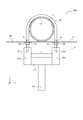
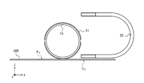
Uボルト取り付け治具100は、橋梁などの構造物に添架された添架部材300に、管路10を固定するためのUボルト20を取り付ける治具である。
The U-bolt attachment jig 100 is a jig for attaching the U-bolt 20 for fixing the pipeline 10 to the attachment member 300 attached to a structure such as a bridge.
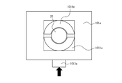
添架部材300は、表面S1が平面であり、管路10を安定して支持可能な構成を有していればよい。添架部材300は、例えば、L形鋼、平鋼、H形鋼などで形成される。添架部材300には、Uボルト20の一端部が挿入されるボルト孔H1およびUボルト20の他端部が挿入されるボルト孔H2が設けられている。
添架member 300 is the surface S 1 is a plane, the conduit 10 may have a stable and capable of supporting a configuration. The supporting member 300 is made of, for example, L-shaped steel, flat steel, H-shaped steel, or the like. The添架member 300, the bolt hole H 2 is provided with the other end of the bolt holes H 1 and U-bolts 20 one end of U-bolt 20 is inserted is inserted.
管路10は、樹脂製又は金属製の管であり、例えば、硬質ビニル管、FRP(Fiber Reinforced Plastics)管、鋼管、FRPM(Fiberglass Reinforced Plastic Mortar)管などである。管路10は、円筒形状を有していればよく、その構成が特に限定されるものではない。例えば、管路10は、継ぎ手などが設けられて、外部に凹凸を有していてもよい。例えば、管路10は、接着剤により接着された保護片11を外部に備えていてもよい(図1参照)。管路10が保護片11を備えることで、管路10がUボルト20により、添架部材300に固定される際に、管路10を保護することが可能となる。なお、図1では、添架部材300に管路10が1本設置される場合を一例に挙げているが、添架部材300に設置される管路10の個数は、特に限定されるものではない。
The pipeline 10 is a resin or metal pipe, for example, a hard vinyl pipe, an FRP (Fiber Reinforced Plastics) pipe, a steel pipe, a FRPM (Fiberglass Reinforced Plastic Mortar) pipe, or the like. The pipeline 10 may have a cylindrical shape, and its configuration is not particularly limited. For example, the pipeline 10 may be provided with a joint or the like and may have irregularities on the outside. For example, the pipeline 10 may be provided with a protective piece 11 bonded with an adhesive to the outside (see FIG. 1). When the pipeline 10 is provided with the protective piece 11, the pipeline 10 can be protected when the pipeline 10 is fixed to the mounting member 300 by the U bolt 20. Note that FIG. 1 cites a case where one pipeline 10 is installed in the auxiliary member 300 as an example, but the number of pipelines 10 installed in the auxiliary member 300 is not particularly limited.
Uボルト20は、中央部が湾曲した形状を有し、側部が直線形状を有し、両端部がボルト構造となっている1本の鋼材である。Uボルト20は、両端部が、ボルト孔H1およびボルト孔H2に挿入されて、管路10、添架部材300、および座金21a,21bを介して、ナット22a,22bと螺合する。これにより、管路10は添架部材300に固定される。
The U-bolt 20 is a single steel material having a curved central portion, a linear shape at the side portions, and a bolt structure at both ends. U-bolt 20, both ends, is inserted into the bolt holes H 1 and bolt holes H 2, line 10,添架member 300, and washers 21a, via 21b, nuts 22a, to 22b and screwed. As a result, the pipeline 10 is fixed to the attachment member 300.
Uボルト取り付け治具100は、嵌合部材(第1嵌合部材)101a,嵌合部材(第2嵌合部材)101bと、保持部材102と、を備える。嵌合部材101aには、嵌合部1011aが設けられている。嵌合部材101bには、嵌合部1011bが設けられている。
The U-bolt mounting jig 100 includes a fitting member (first fitting member) 101a, a fitting member (second fitting member) 101b, and a holding member 102. The fitting member 101a is provided with a fitting portion 1011a. The fitting member 101b is provided with a fitting portion 1011b.
嵌合部材101a,101bは、添架部材300に対して垂直となるように設けられる。嵌合部材101aは、嵌合部1011aにおいて、Uボルト20の一端部と嵌合し、嵌合部材101bは、嵌合部1011bにおいて、Uボルト20の他端部と嵌合する。嵌合部材101aと嵌合部材101bとの間隔Lは、Uボルト20のサイズ(JIS規格)に基づいて、設定される。作業者は、Uボルト20のサイズに合ったUボルト取り付け治具100を適宜選択して使用する。
The fitting members 101a and 101b are provided so as to be perpendicular to the mounting member 300. The fitting member 101a fits with one end of the U bolt 20 at the fitting portion 1011a, and the fitting member 101b fits with the other end of the U bolt 20 at the fitting portion 1011b. The distance L between the fitting member 101a and the fitting member 101b is set based on the size of the U bolt 20 (JIS standard). The operator appropriately selects and uses the U-bolt mounting jig 100 suitable for the size of the U-bolt 20.
保持部材102は、添架部材300に対して平行となるように設けられる。保持部材102は、Uボルト20の両端部を結ぶ直線Dが、添架部材300に対して平行となるように、嵌合部材101a,101bを保持する。嵌合部材101a,101bのZ軸方向の長さを同一にすることにより、保持部材102を添架部材300に対して平行に保持することで、Uボルト20の両端部を結ぶ直線Dを添架部材300に対して平行とすることができる。保持部材102は、一端部が嵌合部材101aと接合し、他端部が嵌合部材101bと接合する。なお、保持部材102と嵌合部材101a,101bとが接合される接合方法は、特に限定されるものではなく、例えば、ボルト接合、溶接接合、接着剤接合など、公知の手法で接合される。
The holding member 102 is provided so as to be parallel to the mounting member 300. The holding member 102 holds the fitting members 101a and 101b so that the straight line D connecting both ends of the U bolt 20 is parallel to the mounting member 300. By making the lengths of the fitting members 101a and 101b in the Z-axis direction the same, the holding member 102 is held in parallel with the mounting member 300, so that the straight line D connecting both ends of the U bolt 20 is connected to the mounting member. It can be parallel to 300. One end of the holding member 102 is joined to the fitting member 101a, and the other end is joined to the fitting member 101b. The joining method for joining the holding member 102 and the fitting members 101a and 101b is not particularly limited, and for example, bolt joining, welding joining, adhesive joining, or the like is used for joining.
作業者は、保持部材102を下方向に引っ張りながら、Uボルト20に、座金21a,21bを介して、ナット22a,22bを締結することで、Uボルト20を添架部材300に対して垂直に取り付けることが可能となる。
The operator attaches the U-bolt 20 perpendicularly to the mounting member 300 by fastening the nuts 22a and 22b to the U-bolt 20 via the washers 21a and 21b while pulling the holding member 102 downward. It becomes possible.
第1実施形態に係るUボルト取り付け治具100は、Uボルト20の両端部と嵌合する嵌合部材101a,101bと、Uボルト20の両端部を結ぶ直線Dが、添架部材300に対して平行となるように、嵌合部材101a,101bを保持する保持部材102と、を備える。作業者は、第1実施形態に係るUボルト取り付け治具100を用いることで、狭隘箇所であっても、部品点数を増やさずに、Uボルト20を添架部材300に対して垂直に取り付けることが可能となる。
In the U-bolt mounting jig 100 according to the first embodiment, the fitting members 101a and 101b that are fitted to both ends of the U-bolt 20 and the straight line D connecting both ends of the U-bolt 20 have a straight line D with respect to the mounting member 300. A holding member 102 for holding the fitting members 101a and 101b is provided so as to be parallel to each other. By using the U-bolt mounting jig 100 according to the first embodiment, the operator can mount the U-bolt 20 perpendicularly to the mounting member 300 without increasing the number of parts even in a narrow place. It will be possible.
<Uボルト取り付け方法>
次に、第1実施形態に係るUボルト取り付け方法について簡単に説明する。 <U-bolt mounting method>
Next, the U-bolt mounting method according to the first embodiment will be briefly described.
次に、第1実施形態に係るUボルト取り付け方法について簡単に説明する。 <U-bolt mounting method>
Next, the U-bolt mounting method according to the first embodiment will be briefly described.
まず、作業者は、Uボルト20を横倒しにして、添架部材300に設置する(図9A参照)。
First, the worker lays the U bolt 20 on its side and installs it on the mounting member 300 (see FIG. 9A).
次に、作業者は、管路10をUボルト20で挟み、Uボルト20が添架部材300に対して垂直となるように、Uボルト20の一端部をボルト孔H1に挿入し、Uボルト20の他端部をボルト孔H2に挿入する(図9B参照)。
Then, the operator, the conduit 10 is sandwiched by U-bolts 20, so that U-bolt 20 is perpendicular to添架member 300 by inserting one end of the U-bolt 20 into the bolt holes H 1, U-bolts the other end of the 20 inserted into the bolt holes H 2 (see FIG. 9B).
次に、作業者は、Uボルト20の一端部におけるネジ山長さlとUボルト20の他端部におけるネジ山長さlとが均等となるように、Uボルト20の両端部の位置を調整する(図9C参照)。
Next, the operator positions both ends of the U-bolt 20 so that the thread length l at one end of the U-bolt 20 and the thread length l at the other end of the U-bolt 20 are equal. Adjust (see FIG. 9C).
次に、作業者は、添架部材300の表面S1と反対側の面S2から、座金21aを介して、Uボルト20の一端部にナット22aを仮締結する。また、作業者は、添架部材300の表面S1と反対側の面S2から、座金21bを介して、Uボルト20の他端部にナット22bを仮締結する(図9D参照)。
Then, the operator, from the surface S 2 of the surface S 1 and the opposite side of the添架member 300, via a washer 21a, is temporarily fastened to the nut 22a on one end of the U-bolt 20. Further, the operator, from the surface S 2 of the surface S 1 and the opposite side of the添架member 300, via the washer 21b, temporarily fastening the nut 22b to the other end of the U-bolt 20 (see FIG. 9D).
次に、作業者は、第1実施形態に係るUボルト取り付け治具100を、Uボルト20に取り付ける(図1参照)。
Next, the operator attaches the U-bolt mounting jig 100 according to the first embodiment to the U-bolt 20 (see FIG. 1).
次に、作業者は、保持部材102を把持して、下方向に引っ張りながら、添架部材300の表面S1と反対側の面S2から、座金21aを介して、Uボルト20の一端部にナット22aを締結し、添架部材300の表面S1と反対側の面S2から、座金21bを介して、Uボルト20の他端部にナット22bを締結する。
Next, the operator grips the holding member 102, while pulling downward, from the face S 2 of the surface S 1 and the opposite side of the添架member 300, via a washer 21a, at one end of the U-bolt 20 concluded nuts 22a, from the surface S 1 and the opposite surface S 2 of添架member 300, via the washer 21b, fastening a nut 22b to the other end of the U-bolt 20.
次に、作業者は、Uボルト取り付け治具100をUボルト20から取り外し、Uボルト20の取り付け作業を終了する。これにより、Uボルト20は、添架部材300に取り付けられ、管路10は、添架部材300に固定される。
Next, the operator removes the U-bolt mounting jig 100 from the U-bolt 20, and completes the mounting work of the U-bolt 20. As a result, the U bolt 20 is attached to the attachment member 300, and the pipeline 10 is fixed to the attachment member 300.
第1実施形態に係るUボルト取り付け方法は、狭隘箇所であっても、部品点数を増やさずに、Uボルト20を添架部材300に対して垂直に取り付けることが可能となる。
The U-bolt mounting method according to the first embodiment makes it possible to mount the U-bolt 20 vertically to the attachment member 300 without increasing the number of parts, even in a narrow place.
[第2実施形態]
<Uボルト取り付け治具の構成>
図2を参照して、第2実施形態に係るUボルト取り付け治具100Aの構成について説明する。 [Second Embodiment]
<Structure of U-bolt mounting jig>
The configuration of theU-bolt mounting jig 100A according to the second embodiment will be described with reference to FIG. 2.
<Uボルト取り付け治具の構成>
図2を参照して、第2実施形態に係るUボルト取り付け治具100Aの構成について説明する。 [Second Embodiment]
<Structure of U-bolt mounting jig>
The configuration of the
第2実施形態に係るUボルト取り付け治具100Aが、第1実施形態に係るUボルト取り付け治具100と異なる点は、第1実施形態に係るUボルト取り付け治具100が、把持部材を備えないのに対して、第2実施形態に係るUボルト取り付け治具100Aは、把持部材を備える点である。なお、その他の構成は、第1実施形態に係るUボルト取り付け治具100と同じであるため、重複した説明を省略する。
The difference between the U-bolt mounting jig 100A according to the second embodiment and the U-bolt mounting jig 100 according to the first embodiment is that the U-bolt mounting jig 100 according to the first embodiment does not include a gripping member. On the other hand, the U-bolt mounting jig 100A according to the second embodiment is provided with a gripping member. Since the other configurations are the same as those of the U-bolt mounting jig 100 according to the first embodiment, duplicated description will be omitted.
把持部材103は、保持部材102の中央部に装着される。把持部材103は、作業者が、手で握り易い形状を有することが好ましく、例えば、棒状の部材で構成される。把持部材103が保持部材102の中央部に装着されることで、把持部材103が作業者により下方向に引っ張られる際に、Uボルト20の両端部にかかる力を均一とすることができる。これにより、Uボルト20の両端部を結ぶ直線Dが、添架部材300に対して平行となり易くなるため、作業者は、容易に、Uボルト20を添架部材300に対して垂直に取り付けることが可能となる。また、把持部材103が保持部材102の中央部に装着されることで、作業者は、保持部材102を下方向に引っ張り易くなるため、Uボルト20を取り付ける際の作業性を向上させることができる。
The grip member 103 is attached to the central portion of the holding member 102. The gripping member 103 preferably has a shape that is easy for an operator to grip by hand, and is composed of, for example, a rod-shaped member. By mounting the gripping member 103 on the central portion of the holding member 102, it is possible to make the force applied to both ends of the U bolt 20 uniform when the gripping member 103 is pulled downward by the operator. As a result, the straight line D connecting both ends of the U-bolt 20 tends to be parallel to the mounting member 300, so that the operator can easily attach the U-bolt 20 perpendicular to the mounting member 300. Will be. Further, since the gripping member 103 is attached to the central portion of the holding member 102, the operator can easily pull the holding member 102 downward, so that the workability when attaching the U bolt 20 can be improved. ..
作業者は、第2実施形態に係るUボルト取り付け治具100Aを用いることで、狭隘箇所であっても、部品点数を増やさずに、Uボルト20を添架部材300に対して垂直に取り付けることが可能となる。
By using the U-bolt mounting jig 100A according to the second embodiment, the operator can mount the U-bolt 20 perpendicularly to the mounting member 300 without increasing the number of parts even in a narrow place. It will be possible.
<Uボルト取り付け方法>
次に、第2実施形態に係るUボルト取り付け方法について簡単に説明する。 <U-bolt mounting method>
Next, the U-bolt mounting method according to the second embodiment will be briefly described.
次に、第2実施形態に係るUボルト取り付け方法について簡単に説明する。 <U-bolt mounting method>
Next, the U-bolt mounting method according to the second embodiment will be briefly described.
まず、作業者は、Uボルト20を横倒しにして、添架部材300に設置する(図9A参照)。
First, the worker lays the U bolt 20 on its side and installs it on the mounting member 300 (see FIG. 9A).
次に、作業者は、管路10をUボルト20で挟み、Uボルト20が添架部材300に対して垂直となるように、Uボルト20の一端部をボルト孔H1に挿入し、Uボルト20の他端部をボルト孔H2に挿入する(図9B参照)。
Then, the operator, the conduit 10 is sandwiched by U-bolts 20, so that U-bolt 20 is perpendicular to添架member 300 by inserting one end of the U-bolt 20 into the bolt holes H 1, U-bolts the other end of the 20 inserted into the bolt holes H 2 (see FIG. 9B).
次に、作業者は、Uボルト20の一端部におけるネジ山長さlとUボルト20の他端部におけるネジ山長さlとが均等となるように、Uボルト20の両端部の位置を調整する(図9C参照)。
Next, the operator positions both ends of the U-bolt 20 so that the thread length l at one end of the U-bolt 20 and the thread length l at the other end of the U-bolt 20 are equal. Adjust (see FIG. 9C).
次に、作業者は、添架部材300の表面S1と反対側の面S2から、座金21aを介して、Uボルト20の一端部にナット22aを仮締結する。また、作業者は、添架部材300の表面S1と反対側の面S2から、座金21bを介して、Uボルト20の他端部にナット22bを仮締結する(図9D参照)。
Then, the operator, from the surface S 2 of the surface S 1 and the opposite side of the添架member 300, via a washer 21a, is temporarily fastened to the nut 22a on one end of the U-bolt 20. Further, the operator, from the surface S 2 of the surface S 1 and the opposite side of the添架member 300, via the washer 21b, temporarily fastening the nut 22b to the other end of the U-bolt 20 (see FIG. 9D).
次に、作業者は、第2実施形態に係るUボルト取り付け治具100Aを、Uボルト20に取り付ける(図2参照)。
Next, the operator attaches the U-bolt attachment jig 100A according to the second embodiment to the U-bolt 20 (see FIG. 2).
次に、作業者は、把持部材103を把持して、下方向に引っ張りながら、添架部材300の表面S1と反対側の面S2から、座金21aを介して、Uボルト20の一端部にナット22aを締結し、添架部材300の表面S1と反対側の面S2から、座金21bを介して、Uボルト20の他端部にナット22bを締結する。
Next, the operator grips the grip member 103, while pulling downward, from the face S 2 of the surface S 1 and the opposite side of the添架member 300, via a washer 21a, at one end of the U-bolt 20 concluded nuts 22a, from the surface S 1 and the opposite surface S 2 of添架member 300, via the washer 21b, fastening a nut 22b to the other end of the U-bolt 20.
次に、作業者は、Uボルト取り付け治具100AをUボルト20から取り外し、Uボルト20の取り付け作業を終了する。これにより、Uボルト20は、添架部材300に取り付けられ、管路10は、添架部材300に固定される。
Next, the operator removes the U-bolt mounting jig 100A from the U-bolt 20, and completes the mounting work of the U-bolt 20. As a result, the U bolt 20 is attached to the attachment member 300, and the pipeline 10 is fixed to the attachment member 300.
第2実施形態に係るUボルト取り付け方法は、狭隘箇所であっても、部品点数を増やさずに、Uボルト20を添架部材300に対して垂直に取り付けることが可能となる。
The U-bolt mounting method according to the second embodiment makes it possible to mount the U-bolt 20 vertically to the attachment member 300 without increasing the number of parts, even in a narrow place.
[第3実施形態]
<Uボルト取り付け治具の構成>
図3Aおよび図3Bを参照して、第3実施形態に係るUボルト取り付け治具100Bの構成について説明する。 [Third Embodiment]
<Structure of U-bolt mounting jig>
The configuration of theU-bolt mounting jig 100B according to the third embodiment will be described with reference to FIGS. 3A and 3B.
<Uボルト取り付け治具の構成>
図3Aおよび図3Bを参照して、第3実施形態に係るUボルト取り付け治具100Bの構成について説明する。 [Third Embodiment]
<Structure of U-bolt mounting jig>
The configuration of the
第3実施形態に係るUボルト取り付け治具100Bが、第1実施形態に係るUボルト取り付け治具100と異なる点は、第1実施形態に係るUボルト取り付け治具100が、貫通部材および固定部材を備えないのに対して、第3実施形態に係るUボルト取り付け治具100Bは、貫通部材および固定部材を備える点である。なお、その他の構成は、第1実施形態に係るUボルト取り付け治具100と同じであるため、重複した説明を省略する。
The U-bolt mounting jig 100B according to the third embodiment is different from the U-bolt mounting jig 100 according to the first embodiment in that the U-bolt mounting jig 100 according to the first embodiment is a penetrating member and a fixing member. However, the U-bolt mounting jig 100B according to the third embodiment is provided with a penetrating member and a fixing member. Since the other configurations are the same as those of the U-bolt mounting jig 100 according to the first embodiment, duplicated description will be omitted.
貫通部材104は、添架部材300に対して平行となるように設けられる。貫通部材104は、添架部材300に対して平行となるように、嵌合部材101a,101bを貫通する(図3B参照)。
The penetrating member 104 is provided so as to be parallel to the mounting member 300. The penetrating member 104 penetrates the fitting members 101a and 101b so as to be parallel to the mounting member 300 (see FIG. 3B).
固定部材105は、貫通部材104と接合する。固定部材105は、貫通部材104と添架部材300との間隔が一定となるように、添架部材300に固定される。固定部材105が設けられることで、貫通部材104と添架部材300との間隔が一定に保たれるため、保持部材102が作業者により下方向に引っ張られる際に、Uボルト20の両端部にかかる力を均一とすることができる。これにより、Uボルト20の両端部を結ぶ直線Dが、添架部材300に対して平行となり易くなるため、作業者は、容易に、Uボルト20を添架部材300に対して垂直に取り付けることが可能となる。
The fixing member 105 is joined to the penetrating member 104. The fixing member 105 is fixed to the mounting member 300 so that the distance between the penetrating member 104 and the mounting member 300 is constant. By providing the fixing member 105, the distance between the penetrating member 104 and the mounting member 300 is kept constant, so that when the holding member 102 is pulled downward by the operator, it is applied to both ends of the U bolt 20. The force can be made uniform. As a result, the straight line D connecting both ends of the U-bolt 20 tends to be parallel to the mounting member 300, so that the operator can easily attach the U-bolt 20 perpendicular to the mounting member 300. Will be.
作業者は、第3実施形態に係るUボルト取り付け治具100Bを用いることで、狭隘箇所であっても、部品点数を増やさずに、Uボルト20を添架部材300に対して垂直に取り
By using the U-bolt mounting jig 100B according to the third embodiment, the operator can take the U-bolt 20 perpendicularly to the mounting member 300 without increasing the number of parts even in a narrow place.
<Uボルト取り付け方法>
次に、第3実施形態に係るUボルト取り付け方法について簡単に説明する。 <U-bolt mounting method>
Next, the U-bolt mounting method according to the third embodiment will be briefly described.
次に、第3実施形態に係るUボルト取り付け方法について簡単に説明する。 <U-bolt mounting method>
Next, the U-bolt mounting method according to the third embodiment will be briefly described.
まず、作業者は、Uボルト20を横倒しにして、添架部材300に設置する(図9A参照)。
First, the worker lays the U bolt 20 on its side and installs it on the mounting member 300 (see FIG. 9A).
次に、作業者は、管路10をUボルト20で挟み、Uボルト20が添架部材300に対して垂直となるように、Uボルト20の一端部をボルト孔H1に挿入し、Uボルト20の他端部をボルト孔H2に挿入する(図9B参照)。
Then, the operator, the conduit 10 is sandwiched by U-bolts 20, so that U-bolt 20 is perpendicular to添架member 300 by inserting one end of the U-bolt 20 into the bolt holes H 1, U-bolts the other end of the 20 inserted into the bolt holes H 2 (see FIG. 9B).
次に、作業者は、Uボルト20の一端部におけるネジ山長さlとUボルト20の他端部におけるネジ山長さlとが均等となるように、Uボルト20の両端部の位置を調整する(図9C参照)。
Next, the operator positions both ends of the U-bolt 20 so that the thread length l at one end of the U-bolt 20 and the thread length l at the other end of the U-bolt 20 are equal. Adjust (see FIG. 9C).
次に、作業者は、添架部材300の表面S1と反対側の面S2から、座金21aを介して、Uボルト20の一端部にナット22aを仮締結する。また、作業者は、添架部材300の表面S1と反対側の面S2から、座金21bを介して、Uボルト20の他端部にナット22bを仮締結する(図9D参照)。
Then, the operator, from the surface S 2 of the surface S 1 and the opposite side of the添架member 300, via a washer 21a, is temporarily fastened to the nut 22a on one end of the U-bolt 20. Further, the operator, from the surface S 2 of the surface S 1 and the opposite side of the添架member 300, via the washer 21b, temporarily fastening the nut 22b to the other end of the U-bolt 20 (see FIG. 9D).
次に、作業者は、第3実施形態に係るUボルト取り付け治具100Bを、Uボルト20に取り付ける(図3A参照)。
Next, the operator attaches the U-bolt mounting jig 100B according to the third embodiment to the U-bolt 20 (see FIG. 3A).
次に、作業者は、保持部材102を把持して、下方向に引っ張りながら、添架部材300の表面S1と反対側の面S2から、座金21aを介して、Uボルト20の一端部にナット22aを締結し、添架部材300の表面S1と反対側の面S2から、座金21bを介して、Uボルト20の他端部にナット22bを締結する。
Next, the operator grips the holding member 102, while pulling downward, from the face S 2 of the surface S 1 and the opposite side of the添架member 300, via a washer 21a, at one end of the U-bolt 20 concluded nuts 22a, from the surface S 1 and the opposite surface S 2 of添架member 300, via the washer 21b, fastening a nut 22b to the other end of the U-bolt 20.
次に、作業者は、Uボルト取り付け治具100BをUボルト20から取り外し、Uボルト20の取り付け作業を終了する。これにより、Uボルト20は、添架部材300に取り付けられ、管路10は、添架部材300に固定される。
Next, the operator removes the U-bolt mounting jig 100B from the U-bolt 20, and completes the mounting work of the U-bolt 20. As a result, the U bolt 20 is attached to the attachment member 300, and the pipeline 10 is fixed to the attachment member 300.
第3実施形態に係るUボルト取り付け方法は、狭隘箇所であっても、部品点数を増やさずに、Uボルト20を添架部材300に対して垂直に取り付けることが可能となる。
付けることが可能となる。 The U-bolt mounting method according to the third embodiment makes it possible to mount the U-bolt 20 vertically to the mountingmember 300 without increasing the number of parts, even in a narrow place.
It becomes possible to attach.
付けることが可能となる。 The U-bolt mounting method according to the third embodiment makes it possible to mount the U-bolt 20 vertically to the mounting
It becomes possible to attach.
[第4実施形態]
<Uボルト取り付け治具の構成>
図4乃至図7Bを参照して、第4実施形態に係るUボルト取り付け治具100Cの構成について説明する。 [Fourth Embodiment]
<Structure of U-bolt mounting jig>
The configuration of the U-bolt mounting jig 100C according to the fourth embodiment will be described with reference to FIGS. 4 to 7B.
<Uボルト取り付け治具の構成>
図4乃至図7Bを参照して、第4実施形態に係るUボルト取り付け治具100Cの構成について説明する。 [Fourth Embodiment]
<Structure of U-bolt mounting jig>
The configuration of the U-bolt mounting jig 100C according to the fourth embodiment will be described with reference to FIGS. 4 to 7B.
Uボルト取り付け治具100Cは、嵌合部材101a,101bと、保持部材102X1と、可動部材106と、を備える。嵌合部材101aは、Uボルト20側に嵌合部1011aが設けられ、保持部材102X1側に凹部1015aが設けられている。嵌合部材101bは、Uボルト20側に嵌合部1011bが設けられ、保持部材102X1側に凹部1015bが設けられている。
U bolt fixture 100C includes engaging members 101a, and 101b, and the holding member 102X 1, a movable member 106, a. Fitting member 101a is fitted portion 1011a is provided in the U-bolt 20, the recess 1015a is provided in the holding member 102X 1 side. Fitting member 101b is fitted portion 1011b is provided on the U-bolt 20, the recess 1015b is provided in the holding member 102X 1 side.
嵌合部材101a,101bは、ボタン1012a,1012bと、ボタン1013a,1013bと、ラッチ機構1014a,1014bと、ゴム部材1016a,1016bと、を備える。保持部材102X1は、凸部1021a,1021bを備える。可動部材106は、ボタン1061a,1061bと、取り付け部1062a,1062bと、ボタン1063と、を備える。
The fitting members 101a and 101b include buttons 1012a and 1012b, buttons 1013a and 1013b, latch mechanisms 1014a and 1014b, and rubber members 1016a and 1016b. The holding member 102X 1 includes convex portions 1021a and 1021b. The movable member 106 includes buttons 1061a and 1061b, mounting portions 1062a and 1062b, and buttons 1063.
嵌合部材101a,101bは、添架部材300に対して垂直となるように設けられる。嵌合部材101aは、嵌合部1011aにおいて、ゴム部材1016aを介して、Uボルト20の一端部と嵌合する。嵌合部材101bは、嵌合部1011bにおいて、ゴム部材1016bを介して、Uボルト20の他端部と嵌合する。作業者がボタン1013a,1013bを押すことにより、ゴム部材1016a,1016bが収縮し、Uボルト20は、嵌合部材101a,101bに固定される(図5Aおよび図5B参照)。嵌合部1011a,1011bは、ソケット式の嵌合部であることが好ましい。これにより、様々なUボルト20の径に対応させて、嵌合部材101a,101bを、Uボルト20の両端部に、嵌合させることができる。
The fitting members 101a and 101b are provided so as to be perpendicular to the mounting member 300. The fitting member 101a is fitted to one end of the U bolt 20 at the fitting portion 1011a via the rubber member 1016a. The fitting member 101b is fitted to the other end of the U bolt 20 at the fitting portion 1011b via the rubber member 1016b. When the operator pushes the buttons 1013a and 1013b, the rubber members 1016a and 1016b contract, and the U bolt 20 is fixed to the fitting members 101a and 101b (see FIGS. 5A and 5B). The fitting portions 1011a and 1011b are preferably socket-type fitting portions. Thereby, the fitting members 101a and 101b can be fitted to both ends of the U bolt 20 in accordance with the diameters of the various U bolts 20.
嵌合部材101aと嵌合部材101bとの間隔Lは、可動部材106により、任意に調整される。例えば、図6Aに示すように、嵌合部材101aと嵌合部材101bとの間隔が、100A用の保持部材102X1に合わせて調整された場合、嵌合部材101aは、凹部1015aが保持部材102X1の凸部1021X1aに嵌められ、嵌合部材101bは、凹部1015bが保持部材102X1の凸部1021X1bに嵌められる。例えば、図6Bに示すように、嵌合部材101aと嵌合部材101bとの間隔が、50A用の保持部材102X2に合わせて調整された場合、嵌合部材101aは、凹部1015aが保持部材102X2の凸部1021X2aに嵌められ、嵌合部材101bは、凹部1015bが保持部材102X2の凸部1021X2bに嵌められる。
The distance L between the fitting member 101a and the fitting member 101b is arbitrarily adjusted by the movable member 106. For example, as shown in FIG. 6A, the interval between the fitting member 101a and the fitting member 101b is, when it is adjusted to the holding member 102X 1 for 100A, the engaging member 101a, the recess 1015a is holding member 102X fitted to one of the convex portion 1021X 1 a, the engaging member 101b, a concave portion 1015b is fitted to the convex portion 1021X 1 b of the holding member 102X 1. For example, as shown in FIG. 6B, the interval between the fitting member 101a and the fitting member 101b is, when it is adjusted to the holding member 102X 2 for 50A, the engaging member 101a, the recess 1015a is holding member 102X fitted into the second protruding portion 1021X 2 a, the engaging member 101b, a concave portion 1015b is fitted to the convex portion 1021X 2 b of the holding member 102X 2.
ボタン1012a,1012bは、嵌合部材101a,101bに保持部材102X1を取り付けるためのボタンである。作業者がボタン1012a,1012bを押すと、保持部材102X1は、嵌合部材101a,101bに固定される。嵌合部材101a,101bがボタン1012a,1012bを備えることで、嵌合部材101a,101bと保持部材102X1とを強固に固定することができるが、嵌合部材101a,101bは、必ずしも、ボタン1012a,1012bを備えていなくてもよい。
Button 1012a, 1012b is a button for attaching the holding member 102X 1 fitting member 101a, to 101b. Operator button 1012a, and press the 1012b, retaining member 102X 1 is fitting member 101a, is secured to 101b. By fitting member 101a, 101b is provided with a button 1012a, 1012b, the engaging member 101a, but 101b and the holding member 102X 1 can be firmly fixed to the fitting member 101a, 101b is necessarily button 1012a , 1012b may not be provided.
ボタン1013a,1013bは、嵌合部1011a,1011bにUボルト20を取り付けるためのボタンである。作業者がボタン1013a,1013bを押すと、ゴム部材1016a,1016bが収縮し、Uボルト20は、嵌合部1011a,1011bに固定される(図5Aおよび図5B参照)。作業者がボタン1013a,1013bを引くと、ゴム部材1016a,1016bが伸長し、Uボルト20は、嵌合部1011a,1011bから取り外される。嵌合部材101a,101bがボタン1013a,1013bを備えることで、嵌合部材101a,101bとUボルト20とを強固に固定することができる。
The buttons 1013a and 1013b are buttons for attaching the U bolt 20 to the fitting portions 1011a and 1011b. When the operator presses the buttons 1013a and 1013b, the rubber members 1016a and 1016b contract, and the U bolt 20 is fixed to the fitting portions 1011a and 1011b (see FIGS. 5A and 5B). When the operator pulls the buttons 1013a and 1013b, the rubber members 1016a and 1016b are extended, and the U bolt 20 is removed from the fitting portions 1011a and 1011b. Since the fitting members 101a and 101b are provided with the buttons 1013a and 1013b, the fitting members 101a and 101b and the U bolt 20 can be firmly fixed.
ゴム部材1016a,1016bは、嵌合部1011a,1011bに設けられ、嵌合部材101a,101bとUボルト20との間に配置される。嵌合部材101a,101bとUボルト20との間に、ゴム部材1016a,1016bが配置されることで、嵌合部材101a,101bとUボルト20とを精度良く強固に固定することができる。
The rubber members 1016a and 1016b are provided in the fitting portions 1011a and 1011b, and are arranged between the fitting members 101a and 101b and the U bolt 20. By arranging the rubber members 1016a and 1016b between the fitting members 101a and 101b and the U bolt 20, the fitting members 101a and 101b and the U bolt 20 can be firmly and accurately fixed.
ラッチ機構1014a,1014bは、作業者が保持部材102X1を下方向に引っ張る場合に、保持部材102X1を下方向に移動させ、作業者が保持部材102X1を上方向に引っ張る場合、保持部材102X1を上方向に固定する機構である。ラッチ機構1014a,1014bは、一定の間隔を空けて、嵌合部材101a,101bに、複数設けられる。嵌合部材101a,101bがラッチ機構1014a,1014bを備えることで、作業者が保持部材102X1から両手を離しても、保持部材102X1が上方向へ戻ることを防ぐことができる。これにより、作業者は、両手で、Uボルト20に、座金21a,21bを介して、ナット22a,22bを締結することができるため、Uボルト20を取り付ける際の作業性を向上させることができる。なお、作業者は、ナット22a,22bを締結した後には、ラッチ機構1014a,1014bを開放することで、添架部材300からUボルト取り付け治具100Cを取り外すことができる。
Latching mechanism 1014a, 1014b, when the operator pulls the holding member 102X 1 downward, the holding member 102X 1 is moved downward, when the operator pulls the holding member 102X 1 upward, the holding member 102X It is a mechanism for fixing 1 in the upward direction. A plurality of latch mechanisms 1014a and 1014b are provided on the fitting members 101a and 101b at regular intervals. Since the fitting members 101a and 101b are provided with the latch mechanisms 1014a and 1014b, it is possible to prevent the holding member 102X 1 from returning upward even if both hands are released from the holding member 102X 1. As a result, the operator can fasten the nuts 22a and 22b to the U bolt 20 with both hands via the washers 21a and 21b, so that the workability when attaching the U bolt 20 can be improved. .. After fastening the nuts 22a and 22b, the operator can remove the U-bolt mounting jig 100C from the mounting member 300 by opening the latch mechanisms 1014a and 1014b.
保持部材102X1は、添架部材300に対して平行となるように設けられる。保持部材102X1は、Uボルト20の両端部を結ぶ直線Dが、添架部材300に対して平行となるように、嵌合部材101a,101bを保持する。保持部材102X1は、一端部が嵌合部材101aと接合し、他端部が嵌合部材101bと接合する。なお、保持部材102X1と嵌合部材101a,101bとが接合される接合方法は、特に限定されるものではなく、例えば、ボルト接合、溶接接合、接着剤接合など、公知の手法で接合される。
The holding member 102X 1 is provided so as to be parallel to the mounting member 300. The holding member 102X 1 holds the fitting members 101a and 101b so that the straight line D connecting both ends of the U bolt 20 is parallel to the mounting member 300. One end of the holding member 102X 1 is joined to the fitting member 101a, and the other end is joined to the fitting member 101b. The joining method in which the holding member 102X 1 and the fitting members 101a and 101b are joined is not particularly limited, and is joined by a known method such as bolt joining, welding joining, or adhesive joining. ..
作業者は、Uボルト20のサイズに合わせて、保持部材を、適宜選択して使用することが好ましい。Uボルト20の呼び寸法が、例えば、50A、80A、100A、130Aである場合、作業者は、50A用の保持部材、80A用の保持部材、100A用の保持部材、130A用の保持部材を、適宜選択して使用することが好ましい。例えば、図6Aに示すように、Uボルト20の呼び寸法が100Aである場合、作業者は、「100A用」の保持部材102X1を選択する。例えば、図6Bに示すように、Uボルト20の呼び寸法が50Aである場合、作業者は、「50A用」の保持部材102X2を選択する。
It is preferable for the operator to appropriately select and use the holding member according to the size of the U bolt 20. When the nominal dimensions of the U-bolt 20 are, for example, 50A, 80A, 100A, 130A, the operator can obtain a holding member for 50A, a holding member for 80A, a holding member for 100A, and a holding member for 130A. It is preferable to select and use it as appropriate. For example, as shown in FIG. 6A, when the nominal dimension of the U-bolt 20 is 100A, the operator selects the holding member 102X 1 of "for 100A". For example, as shown in FIG. 6B, if the nominal dimension of the U-bolt 20 is 50A, the operator selects the holding member 102X 2 of "for 50A".
保持部材は、Uボルト20の呼び寸法が、作業者の見易い位置に記載されていることが好ましい(図6Aおよび図6B参照)。例えば、「100A用」の保持部材102X1には、「100A用」と記載されていることが好ましい。例えば、「50A用」の保持部材102X2には、「50A用」と記載されていることが好ましい。Uボルト20の呼び寸法が、作業者の見易い位置に記載されていることで、作業者は、Uボルト20の呼び寸法に合った保持部材の判別を容易に行うことができる。
For the holding member, it is preferable that the nominal size of the U bolt 20 is described in a position easily visible to the operator (see FIGS. 6A and 6B). For example, the holding member 102X 1 of "for 100A", it has been described as "for 100A" is preferred. For example, it is preferable that the holding member 102X 2 for "50A" is described as "for 50A". Since the nominal size of the U-bolt 20 is described at a position that is easy for the operator to see, the operator can easily determine the holding member that matches the nominal size of the U-bolt 20.
可動部材106は、嵌合部材101aおよび嵌合部材101bに取り付けられる。可動部材106は、添架部材300に対して平行な方向にスライドし(図7Aおよび図7Bの矢印参照)、嵌合部材101aと嵌合部材101bとの間隔Lを調整する。例えば、作業者が可動部材106を右矢印方向にスライドさせると、可動部材106が伸長し、嵌合部材101aと嵌合部材101bとの間隔Lは、長くなる。例えば、作業者が可動部材106を左矢印方向にスライドさせると、可動部材106が収縮し、嵌合部材101aと嵌合部材101bとの間隔Lは、短くなる。これにより、嵌合部材101aと嵌合部材101bとの間隔Lを、Uボルト20のサイズ、保持部材の長さなどに合わせて、適切に調整することが可能となる。
The movable member 106 is attached to the fitting member 101a and the fitting member 101b. The movable member 106 slides in a direction parallel to the mounting member 300 (see the arrows in FIGS. 7A and 7B) to adjust the distance L between the fitting member 101a and the fitting member 101b. For example, when the operator slides the movable member 106 in the direction of the right arrow, the movable member 106 is extended, and the distance L between the fitting member 101a and the fitting member 101b becomes long. For example, when the operator slides the movable member 106 in the direction of the left arrow, the movable member 106 contracts, and the distance L between the fitting member 101a and the fitting member 101b becomes short. As a result, the distance L between the fitting member 101a and the fitting member 101b can be appropriately adjusted according to the size of the U bolt 20, the length of the holding member, and the like.
例えば、図6Aに示すように、Uボルト20の呼び寸法が100Aである場合、作業者は、可動部材106により、嵌合部材101aと嵌合部材101bとの間隔Lを、呼び寸法100AのUボルト20のサイズに合うように調整する。この場合、保持部材102X1の凸部1021X1aは、嵌合部材101aの凹部1015aに嵌められ、保持部材102X1の凸部1021X1bは、嵌合部材101bの凹部1015bに嵌められる。例えば、図6Bに示すように、Uボルト20の呼び寸法が50Aである場合、作業者は、可動部材106により、嵌合部材101aと嵌合部材101bとの間隔Lを、呼び寸法50AのUボルト20のサイズに合うように調整する。この場合、保持部材102X2の凸部1021X2aは、嵌合部材101aの凹部1015aに嵌められ、保持部材102X2の凸部1021X2bは、嵌合部材101bの凹部1015bに嵌められる。なお、Uボルト取り付け治具100Cが使用されないときは、「50A用」の保持部材102X2を嵌合部材101a,101bに差し込んでおくことが好ましい。
For example, as shown in FIG. 6A, when the nominal size of the U bolt 20 is 100A, the operator uses the movable member 106 to set the distance L between the fitting member 101a and the fitting member 101b to be U with a nominal size of 100A. Adjust to fit the size of the bolt 20. In this case, the convex portion 1021X 1 a holding member 102X 1 is fitted into the concave portion 1015a of the engaging member 101a, the convex portion 1021X 1 b of the holding member 102X 1 is fitted in the recess 1015b of the fitting member 101b. For example, as shown in FIG. 6B, when the nominal size of the U bolt 20 is 50A, the operator uses the movable member 106 to set the distance L between the fitting member 101a and the fitting member 101b to be U with a nominal size of 50A. Adjust to fit the size of the bolt 20. In this case, the convex portion 1021X 2 a holding member 102X 2 is fitted into the concave portion 1015a of the engaging member 101a, the convex portion 1021X 2 b of the holding member 102X 2 is fitted into the recess 1015b of the fitting member 101b. Incidentally, when the U-bolt mounting jig 100C is not used, to keep insert the holding member 102X 2 of "for 50A" engaging member 101a, and 101b are preferable.
ボタン1061a,1061bは、可動部材106に嵌合部材101a,101bを固定するためのボタンである。作業者がボタン1061aを押すと、可動部材106に嵌合部材101aが固定され、作業者がボタン1061bを押すと、可動部材106に嵌合部材101bが固定される。可動部材106がボタン1061a,1061bを備えることで、作業者は、保持部材102X1を下方向に引っ張りながら、嵌合部材101a,101bを適切な位置に移動又は固定することができる。
The buttons 1061a and 1061b are buttons for fixing the fitting members 101a and 101b to the movable member 106. When the operator presses the button 1061a, the fitting member 101a is fixed to the movable member 106, and when the operator presses the button 1061b, the fitting member 101b is fixed to the movable member 106. By moving member 106 comprises a button 1061a, 1061b, the operator pulling the holding member 102X 1 downward, can be mobile or fixed engagement members 101a, 101b are in the appropriate position.
ボタン1063は、嵌合部材101a,101bに可動部材106を固定するためのボタンである。作業者がボタン1063を押すと、嵌合部材101a,101bに可動部材106が固定される。可動部材106がボタン1063を備えることで、可動部材106を、添架部材300に対して平行な方向に、任意にスライド又は固定することができる。
The button 1063 is a button for fixing the movable member 106 to the fitting members 101a and 101b. When the operator presses the button 1063, the movable member 106 is fixed to the fitting members 101a and 101b. When the movable member 106 includes the button 1063, the movable member 106 can be arbitrarily slid or fixed in a direction parallel to the mounting member 300.
取り付け部1062a,1062bは、可動部材106を添架部材300に固定する。取り付け部1062a,1062bは、可動部材106の内部に埋め込まれることが好ましい。取り付け部1062a,1062bは、例えば、フック、磁石などであってよいが、その構成は特に限定されない。可動部材106が取り付け部1062a,1062bを備えることで、Uボルト取り付け治具100Cは、添架部材300に固定されるため、作業者は、可動部材106を手で押さえるなどの作業を行わずに済む。これにより、作業者は、両手が塞がって作業がし難いという不便を回避することができる。また、作業者は、両手で、Uボルト20に、座金21a,21bを介して、ナット22a,22bを締結することができるため、Uボルト20を取り付ける際の作業性を向上させることができる。
The mounting portions 1062a and 1062b fix the movable member 106 to the mounting member 300. The mounting portions 1062a and 1062b are preferably embedded inside the movable member 106. The mounting portions 1062a and 1062b may be, for example, hooks, magnets, or the like, but the configuration thereof is not particularly limited. Since the movable member 106 includes the mounting portions 1062a and 1062b, the U-bolt mounting jig 100C is fixed to the mounting member 300, so that the operator does not have to perform work such as pressing the movable member 106 by hand. .. As a result, the worker can avoid the inconvenience that both hands are blocked and it is difficult to work. Further, since the operator can fasten the nuts 22a and 22b to the U bolt 20 with both hands via the washers 21a and 21b, the workability when attaching the U bolt 20 can be improved.
作業者が、保持部材102X1を下方向に引っ張ることで、嵌合部材101a,101bも下方向に引っ張られるが、可動部材106が添架部材300に固定されることで、嵌合部1011a,1011bにかかる力は、取り付け部1062a,1062bと添架部材300との接合部における反力と釣り合う。この結果、保持部材102X1が作業者により下方向に引っ張られる際に、Uボルト20の両端部にかかる力を均一とすることができる。
Operator, the holding member 102X 1 by pulling downward, the engaging member 101a, but 101b also pulled downwardly, by the movable member 106 is fixed to添架member 300, fitting portions 1011a, 1011b The force applied to the mounting portion 1062a, 1062b is balanced with the reaction force at the joint portion between the mounting portions 1062a and 1062b and the mounting member 300. As a result, when the holding member 102X 1 is pulled downward by the operator, the force applied to both ends of the U bolt 20 can be made uniform.
作業者は、第4実施形態に係るUボルト取り付け治具100Cを用いることで、狭隘箇所であっても、部品点数を増やさずに、Uボルト20を添架部材300に対して垂直に取り付けることが可能となる。
By using the U-bolt mounting jig 100C according to the fourth embodiment, the operator can mount the U-bolt 20 perpendicularly to the mounting member 300 without increasing the number of parts even in a narrow place. It will be possible.
また、第4実施形態に係るUボルト取り付け治具100Cは、Uボルトのサイズに応じて、嵌合部材101aと嵌合部材101bとの間隔を、適切に調整することができる。これにより、どんな種類のUボルトであっても、添架部材300に対して垂直に取り付けることが可能となるため、作業者は、Uボルトのサイズを気にすることなく、Uボルトの取り付け作業を行うことができる。
Further, the U-bolt mounting jig 100C according to the fourth embodiment can appropriately adjust the distance between the fitting member 101a and the fitting member 101b according to the size of the U-bolt. As a result, any kind of U-bolt can be attached vertically to the mounting member 300, so that the operator can install the U-bolt without worrying about the size of the U-bolt. It can be carried out.
<Uボルト取り付け方法>
次に、図8、および図9A乃至図9Jを参照して、第4実施形態に係るUボルト取り付け方法について説明する。 <U-bolt mounting method>
Next, the U-bolt mounting method according to the fourth embodiment will be described with reference to FIGS. 8 and 9A to 9J.
次に、図8、および図9A乃至図9Jを参照して、第4実施形態に係るUボルト取り付け方法について説明する。 <U-bolt mounting method>
Next, the U-bolt mounting method according to the fourth embodiment will be described with reference to FIGS. 8 and 9A to 9J.
ステップS101において、図9Aに示すように、作業者は、Uボルト20を横倒しにして、添架部材300に設置する。
In step S101, as shown in FIG. 9A, the operator lays the U bolt 20 sideways and installs it on the mounting member 300.
ステップS102において、図9Bに示すように、作業者は、管路10をUボルト20で挟み、Uボルト20が添架部材300に対して垂直となるように、Uボルト20の一端部をボルト孔H1に挿入し、Uボルト20の他端部をボルト孔H2に挿入する。
In step S102, as shown in FIG. 9B, the operator sandwiches the pipeline 10 with the U bolt 20 and bolts one end of the U bolt 20 so that the U bolt 20 is perpendicular to the mounting member 300. insert the H 1, inserting the other end of the U-bolt 20 into the bolt holes H 2.
ステップS103において、図9Cに示すように、作業者は、Uボルト20の一端部におけるネジ山長さlとUボルト20の他端部におけるネジ山長さlとが均等となるように、Uボルト20の両端部の位置を調整する。
In step S103, as shown in FIG. 9C, the operator U so that the thread length l at one end of the U bolt 20 and the thread length l at the other end of the U bolt 20 are equal. Adjust the positions of both ends of the bolt 20.
ステップS104において、図9Dに示すように、作業者は、添架部材300の表面S1と反対側の面S2から、座金21aを介して、Uボルト20の一端部にナット22aを仮締結する。また、作業者は、添架部材300の表面S1と反対側の面S2から、座金21bを介して、Uボルト20の他端部にナット22bを仮締結する。
In step S104, as shown in FIG. 9D, the operator, from the surface S 2 of the surface S 1 and the opposite side of the添架member 300, via a washer 21a, is temporarily fastened to the nut 22a on one end of the U-bolt 20 .. Further, the operator, from the surface S 2 of the surface S 1 and the opposite side of the添架member 300, via the washer 21b, temporarily fastening the nut 22b to the other end of the U-bolt 20.
ステップS105において、図9Eに示すように、作業者は、可動部材106を、Uボルト20のサイズに合わせて、スライドさせ、嵌合部材101aと嵌合部材101bとの間隔Lを調整し、ボタン1063を押して、嵌合部材101a,101bに可動部材106を固定する。
In step S105, as shown in FIG. 9E, the operator slides the movable member 106 according to the size of the U bolt 20, adjusts the distance L between the fitting member 101a and the fitting member 101b, and presses the button. Press 1063 to fix the movable member 106 to the fitting members 101a and 101b.
ステップS106において、図9Fに示すように、作業者は、嵌合部材101aの凹部1015aに、保持部材102X1の凸部1021X1aを嵌め、嵌合部材101bの凹部1015bに、保持部材102X1の凸部1021X1bを嵌める。そして、作業者は、ボタン1012a,1012bを押して、嵌合部材101a,101bに保持部材102X1を取り付ける。
In step S106, as shown in FIG. 9F, the operator, the recess 1015a of the engaging member 101a, fitted with a convex portion 1021X 1 a holding member 102X 1, the recess 1015b of the fitting member 101b, the holding member 102X 1 The convex portion 1021 X 1 b of the above is fitted. The operator button 1012a, press 1012b, mounting the holding member 102X 1 fitting member 101a, to 101b.
ステップS107において、図9Gに示すように、作業者は、Uボルト20の一端部に嵌合部材101aの嵌合部1011aを嵌合させ、Uボルト20の他端部に嵌合部材101bの嵌合部1011bを嵌合させる。そして、作業者は、ボタン1013a,1013bを押して、Uボルト20を嵌合部材101a,101bに圧着させ固定する。
In step S107, as shown in FIG. 9G, the operator fits the fitting portion 1011a of the fitting member 101a to one end of the U bolt 20, and fits the fitting member 101b to the other end of the U bolt 20. The joint portion 1011b is fitted. Then, the operator pushes the buttons 1013a and 1013b to crimp the U bolt 20 to the fitting members 101a and 101b and fix it.
ステップS108において、図9Hに示すように、作業者は、取り付け部1062a,1062bを介して、可動部材106を添架部材300に固定する。そして、作業者は、保持部材102X1を把持して、下方向に引っ張り、ボタン1061a,1061bを押して、可動部材106に嵌合部材101a,101bを固定する。これにより、Uボルト取り付け治具100Cが、添架部材300に取り付けられる。
In step S108, as shown in FIG. 9H, the operator fixes the movable member 106 to the mounting member 300 via the mounting portions 1062a and 1062b. Then, the operator grips the holding member 102X 1, pulling downward, button 1061a, press 1061b, to secure engagement member 101a, and 101b on the movable member 106. As a result, the U-bolt mounting jig 100C is mounted on the mounting member 300.
そして、作業者は、添架部材300の表面S1と反対側の面S2から、座金21aを介して、Uボルト20の一端部にナット22aを締結する。また、作業者は、添架部材300の表面S1と反対側の面S2から、座金21bを介して、Uボルト20の他端部にナット22bを締結する。
Then, the operator, from the surface S 1 and the opposite surface S 2 of添架member 300, via a washer 21a, fastening a nut 22a on one end of the U-bolt 20. Further, the operator, from the surface S 1 and the opposite surface S 2 of添架member 300, via the washer 21b, fastening a nut 22b to the other end of the U-bolt 20.
ステップS109において、図9Iに示すように、作業者は、Uボルト取り付け治具100Cを、添架部材300から取り外す。
In step S109, as shown in FIG. 9I, the operator removes the U-bolt mounting jig 100C from the mounting member 300.
ステップS110において、図9Jに示すように、作業者は、Uボルト20の取り付け作業を終了する。これにより、Uボルト20は、添架部材300に取り付けられ、管路10は、添架部材300に固定される。
In step S110, as shown in FIG. 9J, the operator finishes the work of attaching the U bolt 20. As a result, the U bolt 20 is attached to the attachment member 300, and the pipeline 10 is fixed to the attachment member 300.
本実施形態に係るUボルト取り付け方法は、上述のステップS101~ステップS110を含む。これにより、狭隘箇所であっても、部品点数を増やさずに、Uボルト20を添架部材300に対して垂直に取り付けることが可能となる。
The U-bolt mounting method according to the present embodiment includes the above-mentioned steps S101 to S110. As a result, the U bolt 20 can be mounted perpendicularly to the mounting member 300 even in a narrow place without increasing the number of parts.
上述の実施形態は代表的な例として説明したが、本開示の趣旨および範囲内で、多くの変更および置換ができることは当業者に明らかである。したがって、本発明は、上述の実施形態により制限するものと解するべきではなく、請求の範囲から逸脱することなく、種々の変形や変更が可能である。また、実施形態のフローチャートに記載の複数の工程を1つに組み合わせたり、あるいは1つの工程を分割したりすることが可能である。
Although the above embodiment has been described as a representative example, it will be apparent to those skilled in the art that many changes and substitutions can be made within the spirit and scope of the present disclosure. Therefore, the present invention should not be construed as being limited by the embodiments described above, and various modifications and modifications can be made without departing from the scope of the claims. Further, it is possible to combine a plurality of steps described in the flowchart of the embodiment into one, or to divide one step.
10 管路
11 保護片
20 Uボルト
21a 座金
21b 座金
22a ナット
22b ナット
100 Uボルト取り付け治具
100A Uボルト取り付け治具
100B Uボルト取り付け治具
100C Uボルト取り付け治具
101a 嵌合部材(第1の嵌合部材)
101b 嵌合部材(第2の嵌合部材)
102 保持部材
103 把持部材
104 貫通部材
105 固定部材
106 可動部材
300 添架部材
1011a 嵌合部
1012a ボタン
1013a ボタン
1014a ラッチ機構
1015a 凹部
1016a ゴム部材
1011b 嵌合部
1012b ボタン
1013b ボタン
1014b ラッチ機構
1015b 凹部
1016b ゴム部材
1021a 凸部
1021b 凸部
1061a ボタン
1062a 取り付け部
1061b ボタン
1062b 取り付け部
1063 ボタン 10Pipeline 11 Protective piece 20 U bolt 21a Seat metal 21b Seat metal 22a Nut 22b Nut 100 U bolt mounting jig 100A U bolt mounting jig 100B U bolt mounting jig 100C U bolt mounting jig 101a Fitting member (first fitting) Jig)
101b Fitting member (second fitting member)
102Holding member 103 Gripping member 104 Penetrating member 105 Fixing member 106 Movable member 300 Attaching member 1011a Fitting part 1012a Button 1013a Button 1014a Latch mechanism 1015a Recess 1016a Rubber member 1011b Fitting part 1012b Button 1013b Button 1014b Recess 1021a Convex part 1021b Convex part 1061a Button 1062a Mounting part 1061b Button 1062b Mounting part 1063 Button
11 保護片
20 Uボルト
21a 座金
21b 座金
22a ナット
22b ナット
100 Uボルト取り付け治具
100A Uボルト取り付け治具
100B Uボルト取り付け治具
100C Uボルト取り付け治具
101a 嵌合部材(第1の嵌合部材)
101b 嵌合部材(第2の嵌合部材)
102 保持部材
103 把持部材
104 貫通部材
105 固定部材
106 可動部材
300 添架部材
1011a 嵌合部
1012a ボタン
1013a ボタン
1014a ラッチ機構
1015a 凹部
1016a ゴム部材
1011b 嵌合部
1012b ボタン
1013b ボタン
1014b ラッチ機構
1015b 凹部
1016b ゴム部材
1021a 凸部
1021b 凸部
1061a ボタン
1062a 取り付け部
1061b ボタン
1062b 取り付け部
1063 ボタン 10
101b Fitting member (second fitting member)
102
Claims (6)
- 管路を添架部材に固定するためのUボルトを取り付けるUボルト取り付け治具であって、
前記添架部材に設けられるボルト孔に挿入される前記Uボルトの両端部と嵌合する第1嵌合部材および第2嵌合部材と、
前記両端部を結ぶ直線が前記添架部材に対して平行となるように、前記第1嵌合部材および前記第2嵌合部材を保持する保持部材と、
を備える、Uボルト取り付け治具。 It is a U-bolt mounting jig that attaches U-bolts for fixing the pipeline to the auxiliary member.
The first fitting member and the second fitting member that are fitted to both ends of the U bolt inserted into the bolt holes provided in the mounting member, and
A holding member for holding the first fitting member and the second fitting member so that a straight line connecting both ends thereof is parallel to the mounting member.
A U-bolt mounting jig. - 前記保持部材の中央部に装着される把持部材をさらに備える、請求項1に記載のUボルト取り付け治具。 The U-bolt mounting jig according to claim 1, further comprising a gripping member mounted at the center of the holding member.
- 前記添架部材に対して平行となるように設けられ、前記第1嵌合部材および前記第2嵌合部材を貫通する貫通部材と、
前記貫通部材と接合し、前記添架部材と前記貫通部材との間隔が一定となるように、前記添架部材に固定される固定部材と、
をさらに備える、請求項1に記載のUボルト取り付け治具。 A penetrating member provided so as to be parallel to the mounting member and penetrating the first fitting member and the second fitting member.
A fixing member that is joined to the penetrating member and fixed to the mounting member so that the distance between the mounting member and the penetrating member is constant.
The U-bolt mounting jig according to claim 1, further comprising. - 前記添架部材に対して平行な方向にスライドし、前記第1嵌合部材と前記第2嵌合部材との間隔を調整する可動部材と、
を備える、請求項1に記載のUボルト取り付け治具。 A movable member that slides in a direction parallel to the mounting member and adjusts the distance between the first fitting member and the second fitting member.
The U-bolt mounting jig according to claim 1. - 管路を添架部材に固定するためのUボルトを取り付けるUボルト取り付け方法であって、
前記Uボルトの両端部を、前記添架部材に設けられるボルト孔に挿入するステップと、
ナットを、前記Uボルトに仮締結するステップと、
前記両端部と嵌合する第1嵌合部材および第2嵌合部材、並びに前記両端部を結ぶ直線が前記添架部材に対して平行となるように、前記第1嵌合部材および前記第2嵌合部材を保持する保持部材を、前記Uボルトに取り付けるステップと、
前記保持部材を、前記添架部材に対して垂直な方向に引っ張るステップと、
前記ナットを、前記Uボルトに締結するステップと、
前記第1嵌合部材、前記第2嵌合部材、および前記保持部材を、前記添架部材から取り外すステップと、
を含む、Uボルト取り付け方法。 It is a U-bolt mounting method that attaches a U-bolt to fix the pipeline to the auxiliary member.
A step of inserting both ends of the U-bolt into bolt holes provided in the mounting member, and
The step of temporarily fastening the nut to the U bolt,
The first fitting member and the second fitting so that the first fitting member and the second fitting member that fit with the both ends and the straight line connecting the both ends are parallel to the mounting member. The step of attaching the holding member for holding the mating member to the U-bolt, and
A step of pulling the holding member in a direction perpendicular to the mounting member,
The step of fastening the nut to the U bolt,
A step of removing the first fitting member, the second fitting member, and the holding member from the mounting member.
U-bolt mounting method, including. - 管路を添架部材に固定するためのUボルトを取り付けるUボルト取り付け方法であって、
前記Uボルトの両端部を、前記添架部材に設けられるボルト孔に挿入するステップと、
ナットを、前記Uボルトに仮締結するステップと、
前記Uボルトの一端部と嵌合する第1嵌合部材と前記Uボルトの他端部と嵌合する第2嵌合部材との間隔を、前記添架部材に対して平行な方向にスライドする可動部材により調整するステップと、
前記両端部を結ぶ直線が前記添架部材に対して平行となるように保持する保持部材を、前記第1嵌合部材および前記第2嵌合部材に取り付けるステップと、
前記可動部材を、前記添架部材に固定するステップと、
前記保持部材を、前記添架部材に対して垂直な方向に引っ張るステップと、
前記ナットを、前記Uボルトに締結するステップと、
前記第1嵌合部材、前記第2嵌合部材、前記可動部材、および前記保持部材を、前記添架部材から取り外すステップと、
を含む、Uボルト取り付け方法。 It is a U-bolt mounting method that attaches a U-bolt to fix the pipeline to the auxiliary member.
A step of inserting both ends of the U-bolt into bolt holes provided in the mounting member, and
The step of temporarily fastening the nut to the U bolt,
Movable to slide the distance between the first fitting member that fits with one end of the U-bolt and the second fitting member that fits with the other end of the U-bolt in a direction parallel to the mounting member. Steps to adjust with parts and
A step of attaching a holding member that holds the straight line connecting both ends so as to be parallel to the mounting member to the first fitting member and the second fitting member.
A step of fixing the movable member to the mounting member,
A step of pulling the holding member in a direction perpendicular to the mounting member,
The step of fastening the nut to the U bolt,
A step of removing the first fitting member, the second fitting member, the movable member, and the holding member from the mounting member.
U-bolt mounting method, including.
Priority Applications (3)
| Application Number | Priority Date | Filing Date | Title |
|---|---|---|---|
| PCT/JP2020/025320 WO2021260937A1 (en) | 2020-06-26 | 2020-06-26 | U-bolt attachment jig and u-bolt attachment method |
| US18/012,592 US20230250898A1 (en) | 2020-06-26 | 2020-06-26 | U-bolt mounting device and u-bolt mounting method |
| JP2022532222A JP7425367B2 (en) | 2020-06-26 | 2020-06-26 | U bolt installation jig and U bolt installation method |
Applications Claiming Priority (1)
| Application Number | Priority Date | Filing Date | Title |
|---|---|---|---|
| PCT/JP2020/025320 WO2021260937A1 (en) | 2020-06-26 | 2020-06-26 | U-bolt attachment jig and u-bolt attachment method |
Publications (1)
| Publication Number | Publication Date |
|---|---|
| WO2021260937A1 true WO2021260937A1 (en) | 2021-12-30 |
Family
ID=79282135
Family Applications (1)
| Application Number | Title | Priority Date | Filing Date |
|---|---|---|---|
| PCT/JP2020/025320 WO2021260937A1 (en) | 2020-06-26 | 2020-06-26 | U-bolt attachment jig and u-bolt attachment method |
Country Status (3)
| Country | Link |
|---|---|
| US (1) | US20230250898A1 (en) |
| JP (1) | JP7425367B2 (en) |
| WO (1) | WO2021260937A1 (en) |
Citations (4)
| Publication number | Priority date | Publication date | Assignee | Title |
|---|---|---|---|---|
| JPS4319759Y1 (en) * | 1965-09-22 | 1968-08-17 | ||
| JPS5943705U (en) * | 1982-09-14 | 1984-03-22 | カルソニックカンセイ株式会社 | clamp metal fittings |
| JPS5968886U (en) * | 1982-10-30 | 1984-05-10 | 陽和産業株式会社 | pipe support |
| JPS59127982U (en) * | 1983-02-17 | 1984-08-28 | 東芝プラント建設株式会社 | U bolt for piping support |
-
2020
- 2020-06-26 WO PCT/JP2020/025320 patent/WO2021260937A1/en active Application Filing
- 2020-06-26 JP JP2022532222A patent/JP7425367B2/en active Active
- 2020-06-26 US US18/012,592 patent/US20230250898A1/en active Pending
Patent Citations (4)
| Publication number | Priority date | Publication date | Assignee | Title |
|---|---|---|---|---|
| JPS4319759Y1 (en) * | 1965-09-22 | 1968-08-17 | ||
| JPS5943705U (en) * | 1982-09-14 | 1984-03-22 | カルソニックカンセイ株式会社 | clamp metal fittings |
| JPS5968886U (en) * | 1982-10-30 | 1984-05-10 | 陽和産業株式会社 | pipe support |
| JPS59127982U (en) * | 1983-02-17 | 1984-08-28 | 東芝プラント建設株式会社 | U bolt for piping support |
Also Published As
| Publication number | Publication date |
|---|---|
| JPWO2021260937A1 (en) | 2021-12-30 |
| US20230250898A1 (en) | 2023-08-10 |
| JP7425367B2 (en) | 2024-01-31 |
Similar Documents
| Publication | Publication Date | Title |
|---|---|---|
| US8038106B2 (en) | Fast beam clamp | |
| US7635108B2 (en) | Cable holder for aircraft | |
| WO2021260937A1 (en) | U-bolt attachment jig and u-bolt attachment method | |
| US20100032535A1 (en) | Clamping Device | |
| US10843640B2 (en) | Vehicle with locator device configured to maintain outer body panel alignment, and corresponding method | |
| JP6058893B2 (en) | Brace material mounting bracket and brace material mounting method using the same | |
| GB2457711A (en) | Tension device | |
| JP5041365B2 (en) | Outdoor communication device installation structure and installation method | |
| JP4093560B2 (en) | Parent rope support | |
| WO2021186639A1 (en) | U-bolt attachment jig and u-bolt attachment method | |
| JP2009144809A (en) | Clamp for pipe body joint | |
| US7712731B2 (en) | Gutter clamp | |
| CN212510163U (en) | Support arm | |
| JP3216172U (en) | Antenna installation assist device | |
| KR20080091554A (en) | Pipe hanger structure | |
| CN211598751U (en) | Steel cable fixing device for tunnel and inspection device | |
| JP5992083B1 (en) | Fall-out prevention fitting for lighting equipment and fall-off prevention method | |
| JP2005321065A (en) | Support metal-fitting for general section-steel | |
| CN217683625U (en) | Pipeline clamp convenient to assemble | |
| JPH0714285U (en) | Pipe support bracket | |
| CN218529578U (en) | Section bar hanging point installation assembly and suspension device | |
| US11187353B1 (en) | Strut channel mounting clip | |
| JP2006062014A (en) | Chain fitting tool | |
| US20050274856A1 (en) | Clamp for use with motorcycle accessories | |
| JP4181588B2 (en) | Manual carrier reinforcement and manual carrier equipped with it |
Legal Events
| Date | Code | Title | Description |
|---|---|---|---|
| 121 | Ep: the epo has been informed by wipo that ep was designated in this application |
Ref document number: 20942096 Country of ref document: EP Kind code of ref document: A1 |
|
| ENP | Entry into the national phase |
Ref document number: 2022532222 Country of ref document: JP Kind code of ref document: A |
|
| NENP | Non-entry into the national phase |
Ref country code: DE |
|
| 122 | Ep: pct application non-entry in european phase |
Ref document number: 20942096 Country of ref document: EP Kind code of ref document: A1 |