WO2021256563A1 - 熱交換器、熱交換器ユニット、及び冷凍サイクル装置 - Google Patents
熱交換器、熱交換器ユニット、及び冷凍サイクル装置 Download PDFInfo
- Publication number
- WO2021256563A1 WO2021256563A1 PCT/JP2021/023223 JP2021023223W WO2021256563A1 WO 2021256563 A1 WO2021256563 A1 WO 2021256563A1 JP 2021023223 W JP2021023223 W JP 2021023223W WO 2021256563 A1 WO2021256563 A1 WO 2021256563A1
- Authority
- WO
- WIPO (PCT)
- Prior art keywords
- heat exchanger
- refrigerant
- flat tube
- flat
- fin
- Prior art date
- Legal status (The legal status is an assumption and is not a legal conclusion. Google has not performed a legal analysis and makes no representation as to the accuracy of the status listed.)
- Ceased
Links
Images











Classifications
-
- F—MECHANICAL ENGINEERING; LIGHTING; HEATING; WEAPONS; BLASTING
- F28—HEAT EXCHANGE IN GENERAL
- F28F—DETAILS OF HEAT-EXCHANGE AND HEAT-TRANSFER APPARATUS, OF GENERAL APPLICATION
- F28F1/00—Tubular elements; Assemblies of tubular elements
- F28F1/10—Tubular elements and assemblies thereof with means for increasing heat-transfer area, e.g. with fins, with projections, with recesses
- F28F1/12—Tubular elements and assemblies thereof with means for increasing heat-transfer area, e.g. with fins, with projections, with recesses the means being only outside the tubular element
- F28F1/24—Tubular elements and assemblies thereof with means for increasing heat-transfer area, e.g. with fins, with projections, with recesses the means being only outside the tubular element and extending transversely
- F28F1/32—Tubular elements and assemblies thereof with means for increasing heat-transfer area, e.g. with fins, with projections, with recesses the means being only outside the tubular element and extending transversely the means having portions engaging further tubular elements
- F28F1/325—Fins with openings
-
- F—MECHANICAL ENGINEERING; LIGHTING; HEATING; WEAPONS; BLASTING
- F25—REFRIGERATION OR COOLING; COMBINED HEATING AND REFRIGERATION SYSTEMS; HEAT PUMP SYSTEMS; MANUFACTURE OR STORAGE OF ICE; LIQUEFACTION SOLIDIFICATION OF GASES
- F25B—REFRIGERATION MACHINES, PLANTS OR SYSTEMS; COMBINED HEATING AND REFRIGERATION SYSTEMS; HEAT PUMP SYSTEMS
- F25B39/00—Evaporators; Condensers
- F25B39/02—Evaporators
-
- F—MECHANICAL ENGINEERING; LIGHTING; HEATING; WEAPONS; BLASTING
- F25—REFRIGERATION OR COOLING; COMBINED HEATING AND REFRIGERATION SYSTEMS; HEAT PUMP SYSTEMS; MANUFACTURE OR STORAGE OF ICE; LIQUEFACTION SOLIDIFICATION OF GASES
- F25B—REFRIGERATION MACHINES, PLANTS OR SYSTEMS; COMBINED HEATING AND REFRIGERATION SYSTEMS; HEAT PUMP SYSTEMS
- F25B39/00—Evaporators; Condensers
- F25B39/04—Condensers
-
- F—MECHANICAL ENGINEERING; LIGHTING; HEATING; WEAPONS; BLASTING
- F28—HEAT EXCHANGE IN GENERAL
- F28F—DETAILS OF HEAT-EXCHANGE AND HEAT-TRANSFER APPARATUS, OF GENERAL APPLICATION
- F28F17/00—Removing ice or water from heat-exchange apparatus
- F28F17/005—Means for draining condensates from heat exchangers, e.g. from evaporators
-
- F—MECHANICAL ENGINEERING; LIGHTING; HEATING; WEAPONS; BLASTING
- F28—HEAT EXCHANGE IN GENERAL
- F28F—DETAILS OF HEAT-EXCHANGE AND HEAT-TRANSFER APPARATUS, OF GENERAL APPLICATION
- F28F9/00—Casings; Header boxes; Auxiliary supports for elements; Auxiliary members within casings
- F28F9/02—Header boxes; End plates
- F28F9/0202—Header boxes having their inner space divided by partitions
- F28F9/0204—Header boxes having their inner space divided by partitions for elongated header box, e.g. with transversal and longitudinal partitions
-
- F—MECHANICAL ENGINEERING; LIGHTING; HEATING; WEAPONS; BLASTING
- F28—HEAT EXCHANGE IN GENERAL
- F28F—DETAILS OF HEAT-EXCHANGE AND HEAT-TRANSFER APPARATUS, OF GENERAL APPLICATION
- F28F9/00—Casings; Header boxes; Auxiliary supports for elements; Auxiliary members within casings
- F28F9/02—Header boxes; End plates
- F28F9/026—Header boxes; End plates with static flow control means, e.g. with means for uniformly distributing heat exchange media into conduits
- F28F9/0265—Header boxes; End plates with static flow control means, e.g. with means for uniformly distributing heat exchange media into conduits by using guiding means or impingement means inside the header box
-
- F—MECHANICAL ENGINEERING; LIGHTING; HEATING; WEAPONS; BLASTING
- F28—HEAT EXCHANGE IN GENERAL
- F28F—DETAILS OF HEAT-EXCHANGE AND HEAT-TRANSFER APPARATUS, OF GENERAL APPLICATION
- F28F9/00—Casings; Header boxes; Auxiliary supports for elements; Auxiliary members within casings
- F28F9/02—Header boxes; End plates
- F28F9/026—Header boxes; End plates with static flow control means, e.g. with means for uniformly distributing heat exchange media into conduits
- F28F9/028—Header boxes; End plates with static flow control means, e.g. with means for uniformly distributing heat exchange media into conduits by using inserts for modifying the pattern of flow inside the header box, e.g. by using flow restrictors or permeable bodies or blocks with channels
-
- F—MECHANICAL ENGINEERING; LIGHTING; HEATING; WEAPONS; BLASTING
- F25—REFRIGERATION OR COOLING; COMBINED HEATING AND REFRIGERATION SYSTEMS; HEAT PUMP SYSTEMS; MANUFACTURE OR STORAGE OF ICE; LIQUEFACTION SOLIDIFICATION OF GASES
- F25B—REFRIGERATION MACHINES, PLANTS OR SYSTEMS; COMBINED HEATING AND REFRIGERATION SYSTEMS; HEAT PUMP SYSTEMS
- F25B13/00—Compression machines, plants or systems, with reversible cycle
-
- F—MECHANICAL ENGINEERING; LIGHTING; HEATING; WEAPONS; BLASTING
- F25—REFRIGERATION OR COOLING; COMBINED HEATING AND REFRIGERATION SYSTEMS; HEAT PUMP SYSTEMS; MANUFACTURE OR STORAGE OF ICE; LIQUEFACTION SOLIDIFICATION OF GASES
- F25B—REFRIGERATION MACHINES, PLANTS OR SYSTEMS; COMBINED HEATING AND REFRIGERATION SYSTEMS; HEAT PUMP SYSTEMS
- F25B41/00—Fluid-circulation arrangements
- F25B41/40—Fluid line arrangements
- F25B41/42—Arrangements for diverging or converging flows, e.g. branch lines or junctions
-
- F—MECHANICAL ENGINEERING; LIGHTING; HEATING; WEAPONS; BLASTING
- F28—HEAT EXCHANGE IN GENERAL
- F28D—HEAT-EXCHANGE APPARATUS, NOT PROVIDED FOR IN ANOTHER SUBCLASS, IN WHICH THE HEAT-EXCHANGE MEDIA DO NOT COME INTO DIRECT CONTACT
- F28D1/00—Heat-exchange apparatus having stationary conduit assemblies for one heat-exchange medium only, the media being in contact with different sides of the conduit wall, in which the other heat-exchange medium is a large body of fluid, e.g. domestic or motor car radiators
- F28D1/02—Heat-exchange apparatus having stationary conduit assemblies for one heat-exchange medium only, the media being in contact with different sides of the conduit wall, in which the other heat-exchange medium is a large body of fluid, e.g. domestic or motor car radiators with heat-exchange conduits immersed in the body of fluid
- F28D1/04—Heat-exchange apparatus having stationary conduit assemblies for one heat-exchange medium only, the media being in contact with different sides of the conduit wall, in which the other heat-exchange medium is a large body of fluid, e.g. domestic or motor car radiators with heat-exchange conduits immersed in the body of fluid with tubular conduits
- F28D1/053—Heat-exchange apparatus having stationary conduit assemblies for one heat-exchange medium only, the media being in contact with different sides of the conduit wall, in which the other heat-exchange medium is a large body of fluid, e.g. domestic or motor car radiators with heat-exchange conduits immersed in the body of fluid with tubular conduits the conduits being straight
- F28D1/0535—Heat-exchange apparatus having stationary conduit assemblies for one heat-exchange medium only, the media being in contact with different sides of the conduit wall, in which the other heat-exchange medium is a large body of fluid, e.g. domestic or motor car radiators with heat-exchange conduits immersed in the body of fluid with tubular conduits the conduits being straight the conduits having a non-circular cross-section
- F28D1/05366—Assemblies of conduits connected to common headers, e.g. core type radiators
-
- F—MECHANICAL ENGINEERING; LIGHTING; HEATING; WEAPONS; BLASTING
- F28—HEAT EXCHANGE IN GENERAL
- F28F—DETAILS OF HEAT-EXCHANGE AND HEAT-TRANSFER APPARATUS, OF GENERAL APPLICATION
- F28F1/00—Tubular elements; Assemblies of tubular elements
- F28F1/02—Tubular elements of cross-section which is non-circular
- F28F1/022—Tubular elements of cross-section which is non-circular with multiple channels
-
- F—MECHANICAL ENGINEERING; LIGHTING; HEATING; WEAPONS; BLASTING
- F28—HEAT EXCHANGE IN GENERAL
- F28F—DETAILS OF HEAT-EXCHANGE AND HEAT-TRANSFER APPARATUS, OF GENERAL APPLICATION
- F28F2215/00—Fins
- F28F2215/08—Fins with openings, e.g. louvers
-
- F—MECHANICAL ENGINEERING; LIGHTING; HEATING; WEAPONS; BLASTING
- F28—HEAT EXCHANGE IN GENERAL
- F28F—DETAILS OF HEAT-EXCHANGE AND HEAT-TRANSFER APPARATUS, OF GENERAL APPLICATION
- F28F2215/00—Fins
- F28F2215/12—Fins with U-shaped slots for laterally inserting conduits
-
- F—MECHANICAL ENGINEERING; LIGHTING; HEATING; WEAPONS; BLASTING
- F28—HEAT EXCHANGE IN GENERAL
- F28F—DETAILS OF HEAT-EXCHANGE AND HEAT-TRANSFER APPARATUS, OF GENERAL APPLICATION
- F28F2265/00—Safety or protection arrangements; Arrangements for preventing malfunction
- F28F2265/06—Safety or protection arrangements; Arrangements for preventing malfunction by using means for draining heat exchange media from heat exchangers
Definitions
- a multi-flow heat exchanger having a plurality of flat tubes, a plurality of fins, and a pair of headers.
- the plurality of flat tubes are inserted into the plurality of fins at intervals in the vertical direction.
- Each flat tube is formed with a plurality of flow paths arranged at intervals in the width direction.
- the plurality of fins are arranged at intervals in the direction in which the flat tube extends.
- Each pair of headers extends in the vertical direction.
- One header is connected to the plurality of flat tubes in a state of accommodating one end of the plurality of flat tubes.
- the other header is connected to the plurality of flat tubes, accommodating the other end of the plurality of flat tubes.
- the heat exchanger when used as an evaporator, a gas-liquid two-phase refrigerant is introduced into the header from the outside as a refrigerant.
- the bias of the refrigerant distribution to each flat pipe and the plurality of flow paths formed in each flat pipe is not dependent on the flow rate of the refrigerant introduced into the header. It needs to be suppressed.
- the refrigerant distribution to each flat pipe is biased due to the influence of inertial force and gravity.
- Patent Document 1 discloses a heat exchanger for the purpose of suppressing the drift of the refrigerant due to the circulation amount of the refrigerant. Specifically, Patent Document 1 describes a first straightening vane that partitions a first internal space arranged below the internal space of the header and a space arranged above the first internal space, and a first rectifying plate. A first partition plate that divides the space arranged above the internal space into a first outflow space and a first loop space is provided, and a first inflow port formed in the first straightening vane is provided. (1) A heat exchanger that guides a refrigerant introduced into an internal space to a first outflow space and circulates the refrigerant between the first outflow space and the first loop space is disclosed.
- the fins of the heat exchanger having a flat shape, a plate-shaped fin body extending in the vertical direction and having a thin thickness, a plurality of flat tube insertion portions into which the flat tubes are inserted, and from the upper side to the lower side. And some have a communication part that guides the condensed water.
- the flat tube insertion portion is formed in the fin body and extends in the left-right direction orthogonal to the up-down direction.
- the flat tube insertion portion is formed so that the flat tube insertion portion does not divide the fin body in the left-right direction.
- the communication portion is composed of a portion of the fin body located outside the plurality of flat tube insertion portions. The communication portion extends continuously in the vertical direction.
- Patent Document 2 between the fin spacing adjusting portions formed in the communication portion and formed at intervals in the vertical direction, the fin spacing adjusting portions face each other in the left-right direction and face the flat tube insertion portion, and the arrangement directions of a plurality of fins (
- fin arrangement direction a heat transfer promoting portion projecting to one side
- a plurality of heat transfer promoting portions are arranged at intervals in the vertical direction.
- Patent Document 3 discloses that the spacing (fin pitch) between fins adjacent to each other is defined by the first and second spacing holding portions formed on the plate-shaped fins.
- the first spacing holding portion is formed on the leading edge (edge located on the upstream side in the air flow direction) side of the flat tube in a state where the flat tube is arranged on the fin.
- the second spacing holding portion is formed in fins located between the flat tubes arranged in the vertical direction.
- Patent Document 3 discloses that a first and second space holding portions are formed by bending a part of fins. Further, Patent Document 3 discloses that a part of the fin is bent so as to face the air flow direction when the first spacing holding portion is formed. Further, Patent Document 3 discloses a configuration in which the tip end portion of the flat tube is in contact with only a part of the first spacing holding portion.
- the space in the header is divided into a plurality of spaces by arranging the horizontal partition plates extending in the horizontal direction in the header in the vertical direction. ing.
- the number of horizontal partition plates may increase, which may complicate the manufacturing process.
- Patent Document 1 in order to guide the refrigerant introduced into the first internal space to the first outflow space through the two first inflow ports formed in the first straightening vane, the refrigerant is introduced in the width direction of the flat tube. State may be different. In this case, it may be difficult to suppress the bias of the refrigerant distribution with respect to the plurality of flow paths formed in the width direction of each flat tube.
- the heat transfer promoting portion disclosed in Patent Document 2 is formed by pressing a plate-shaped base material member which is a base material of fins. Therefore, a depression having a bottom is formed on the other side of the heat transfer promoting portion in the fin arrangement direction. As a result, the condensed water flowing through the communicating portion may accumulate at the bottom of the heat transfer promoting portion, making it difficult to drain the condensed water downward through the communicating portion.
- Patent Document 3 when forming the first spacing holding portion, a part of the fin is bent so as to face the air flow direction. Therefore, the first interval holding portion becomes a flow resistance, and there is a possibility that the pressure loss of air increases. Further, in Patent Document 3, since the tip portion of the flat tube comes into contact with only a part of the first spacing holding portion, it may be difficult to improve the thermal conductivity between the fin and the flat tube. be.
- the present disclosure has been made to solve the above problems, and it is possible to simplify the manufacturing process, and the flow rate of the refrigerant supplied in the header does not depend on the flow rate of each flat tube and each flat tube. It is an object of the present invention to provide a heat exchanger, a heat exchanger unit, and a refrigeration cycle device capable of suppressing a bias in refrigerant distribution with respect to a plurality of flow paths formed in the width direction. Further, the present disclosure has been made in order to solve the above-mentioned problems, and is a heat exchanger capable of suppressing the collapse of fins while suppressing the obstruction of the flow of condensed water in the communication portion, heat. It is an object of the present invention to provide a exchanger unit and a refrigeration cycle device.
- the present disclosure has been made to solve the above-mentioned problems, and it is possible to specify the fin pitch while suppressing the pressure loss of air, and heat conduction between the flat tube and the fins. It is an object of the present invention to provide a heat exchanger, a heat exchanger unit, and a refrigeration cycle device capable of improving the properties.
- the heat exchanger is a heat exchanger that exchanges heat between air and a refrigerant, and has a flat outer shape that extends in one direction and is arranged in the width direction.
- a plurality of flat tubes extending in one direction and having a plurality of flow paths through which the refrigerant flows, and a plurality of fins arranged in the extending direction of the flat tubes in a state of accommodating the plurality of flat tubes. It is connected to the plurality of flat tubes so that one end of the plurality of flat tubes is arranged inside, and includes a header through which the refrigerant flows, and the header is a cylinder extending in the vertical direction.
- a header body having a shape and partitioning a columnar internal space, and the extension in a state of being housed in the header body, extending in the vertical direction, and allowing the refrigerant to flow at the upper end and the lower end of the internal space.
- a partition plate that divides the internal space into a first space and a second space in which one end of the plurality of flat tubes is arranged in the direction, and a header arranged below the first space. It has a nozzle portion including an outlet that blows out the refrigerant supplied from the outside of the header body toward the bottom surface of the header body, and is a part of the first space on both sides of the nozzle portion in the width direction. Refrigerant flow sections are formed respectively.
- the heat exchanger is a heat exchanger that exchanges heat between air and a refrigerant, has a flat outer shape, and has a flow path through which the refrigerant flows inside.
- the first surface is provided with a plurality of fins arranged at a predetermined pitch in the extending direction of the flat tube, and the plurality of fins have a plate shape and are arranged in the extending direction.
- a fin body including a second surface arranged on the opposite side of the first surface, and a plurality of fin bodies formed on the fin body and arranged at intervals in the vertical direction orthogonal to the extending direction.
- a plurality of flat tube insertion portions extending from one side in the left-right direction orthogonal to the vertical direction and the extending direction to the other side and accommodating the flat tube inserted from the second end side. It has a communication portion that is arranged on the other side of the flat tube insertion portion in the left-right direction and extends continuously in the vertical direction, and the communication portion is parallel to the vertical direction and the left-right direction.
- the communication portion includes the first flat portion, is bent in a direction intersecting the first flat portion, continuously extends in the vertical direction, and is orthogonal to the vertical direction.
- a condensed water guide portion is formed in which the cross-sectional shape when cut in a plane is uniform in the vertical direction.
- the heat exchanger has a flat outer shape, a flow path through which a refrigerant flows is formed inside, and a first end arranged on one side in the width direction.
- a plurality of flat tubes having a portion and a second end arranged on the other side in the width direction, and the plurality of flat tubes are accommodated and arranged at a predetermined pitch in the extending direction of the flat tubes.
- the plurality of fins are provided with a plurality of fins, the plurality of fins having a plate shape, a first surface arranged in the extending direction, and a second surface arranged on the opposite side of the first surface.
- a plurality of fin bodies including the above, and a plurality of fin bodies formed in the fin body and arranged at intervals in a first direction orthogonal to the extending direction, with respect to the first direction and the extending direction.
- a flat tube insertion portion extending from one side to the other side in an orthogonal second direction and accommodating the flat tube inserted from the second end side, and the second flat tube insertion portion rather than the plurality of flat tube insertion portions.
- a part of the fin body located between the communication portion arranged on the other side in the direction of the above and continuously extending in the first direction and the flat tube insertion portion adjacent to each other in the first direction.
- a first fin pitch defining portion formed by bending in the first direction and projecting toward the first surface side and abutting on the fins arranged on one side in the extending direction, and the above.
- the flat tube insertion portion formed by bending a part of the fin body in the first direction and projecting toward the first surface side, and is located on the rear end portion side of the tip end portion of the flat tube insertion portion. It has a second fin pitch defining portion which is arranged around the above and is in contact with the fins arranged on one side of the extending direction, and is located on one side from the other side in the second direction.
- Air that exchanges heat with the refrigerant is flowing in the direction toward the direction of the pipe, and the outer shape of the second end is circular or elliptical, and the flat tube insertion portion that accommodates the second end.
- the shape of the tip portion of the above is such that the outer peripheral surface of the second end portion and the fin body are in surface contact with each other, and the first fin pitch defining portion is on the rear end portion side of the flat tube insertion portion.
- the second fin pitch defining portion is arranged on the tip end side of the flat tube insertion portion.
- each flatness is suppressed without complicating the manufacturing process and does not depend on the flow rate of the refrigerant supplied in the header. It is possible to suppress the bias of the refrigerant distribution with respect to a plurality of flow paths formed in the width direction of the pipe and each flat pipe.
- the heat exchanger, the heat exchanger unit, and the refrigerating cycle apparatus of the present disclosure it is possible to suppress the obstruction of the flow of condensed water in the communication portion and also to suppress the collapse of the fins.
- the fin pitch can be defined while suppressing the pressure loss of air, and the thermal conductivity between the flat tube and the fin is improved. Can be made to.
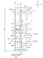
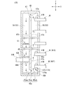
- FIG. 1 shows schematic structure of the refrigerating cycle apparatus which concerns on 1st Embodiment of this disclosure. It is a figure which shows typically the main part of the heat exchanger shown in FIG. It is a perspective view of the flat tube shown in FIG. It is a vertical sectional view of the header surrounded by the area B shown in FIG. It is a cross-sectional view of a C 1 -C 2 along the line of the header shown in FIG. It is a cross-sectional view of D 1 -D 2 along the line of the header shown in FIG. It is sectional drawing of the main part of the heat exchanger which concerns on 1st modification of 1st Embodiment.
- FIG. 22 It is a vertical sectional view of the main part of the heat exchanger which concerns on the 5th modification of 4th Embodiment. It is a figure which shows typically the schematic structure of the refrigerating cycle apparatus which concerns on 5th Embodiment of this disclosure. It is a figure which shows typically the main part of the heat exchanger shown in FIG. It is a figure which A-viewed the flat tube and fin shown in FIG. It is a perspective view of the flat tube shown in FIG. 22. It is a cross-sectional view of E 1 -E 2 along the line of the fin shown in FIG. 23 is a diagram showing a cross section of one fin. It is a cross-sectional view of the F 1 -F 2 along the line of the fin shown in FIG.
- FIG. 23 is a sectional view showing a state where the fin pitch defining portion is in contact with the fins which is arranged at a position adjacent schematically. It is a cross-sectional view of G 1 -G 2 along the line of the fin shown in FIG. 22 is a diagram showing a cross section of one fin. It is a top view for demonstrating the pre-process of the cutting process performed at the time of manufacturing a plurality of fins shown in FIG. 22. It is a top view for demonstrating the cutting process performed at the time of manufacturing a plurality of fins shown in FIG. 22. It is a top view for demonstrating another arrangement example of the plurality of fins when manufacturing the plurality of fins shown in FIG. 22.
- FIG. 31 is a cross-sectional view of the fins shown in FIG. 31 in the I 1- I 2- line direction, and is a view showing a cross section of one fin. It is a figure which shows the main part of the heat exchanger which concerns on 7th Embodiment of this disclosure. It is a cross-sectional view of K 1 -K 2 along the line of the fin shown in FIG. 33 is a diagram showing a cross section of one fin. It is a figure which shows the main part of the heat exchanger which concerns on 8th Embodiment of this disclosure.
- FIG. 40 It is a figure which shows typically the main part of the heat exchanger shown in FIG. 40. It is a figure which A-viewed the flat tube and fin shown in FIG. 41. It is a cross-sectional view of Q 1 -Q 2 along the line of the fin shown in FIG. 42 is a diagram showing a cross section of one fin. It is a cross-sectional view of the R 1 -R 2 along the line of the fin shown in FIG. 42 is a diagram showing a cross section of one fin.
- the refrigeration cycle device 10 has a configuration in which a four-way valve 15, a compressor 16, a first heat exchanger unit 18, an expansion valve 19, and a second heat exchanger unit 23 are connected by a refrigerant pipe 14.
- the refrigeration cycle device 10 includes an outdoor unit 11 and an indoor unit 12.
- the outdoor unit 11 has a four-way valve 15, a compressor 16, a first heat exchanger unit 18, and an expansion valve 19.
- the four-way valve 15 has connecting portions 15A to 15D to which any one of both ends of the first and second refrigerant pipes 14A and 14B constituting the refrigerant pipe 14 is connected.
- One end of the first refrigerant pipe 14A is connected to the connection portion 15A.
- the other end of the first refrigerant pipe 14A is connected to the connection portion 15B.
- One end of the second refrigerant pipe 14B is connected to the connection portion 15C.
- the other end of the second refrigerant pipe 14B is connected to the connection portion 15D.
- the four-way valve 15 having the above configuration switches the direction in which the refrigerant flows between the heating operation and the cooling operation. Specifically, during the cooling operation, the refrigerant is circulated in the order of the compressor 16, the first heat exchanger unit 18, the expansion valve 19, and the second heat exchanger unit 23. On the other hand, during the heating operation, the refrigerant is circulated in the order of the compressor 16, the second heat exchanger unit 23, the expansion valve 19, and the first heat exchanger unit 18.
- the compressor 16 is provided in the second refrigerant pipe 14B.
- the compressor 16 compresses the refrigerant flowing through the second refrigerant pipe 14B.
- the first heat exchanger unit 18 has a first blower 26 and a heat exchanger 27.
- the first blower 26 supplies air to the heat exchanger 27.
- the heat exchanger 27 will be described with reference to FIGS. 1 to 6.
- the Z direction indicates a vertical direction.
- the X direction indicates the extending direction of the flat tube 41 orthogonal to the Z direction.
- the Y direction indicates the width direction of the flat tube 41 (the width direction of the nozzle portion 49) orthogonal to the X direction and the Z direction.
- air flows in the direction of the paper surface for example, the direction toward the paper surface.
- the arrows shown in FIG. 4 indicate the direction in which the refrigerant flows when the heat exchanger 27 is used as an evaporator, and H indicates the height of the header body 45 (hereinafter referred to as “height H”).
- the heat exchanger 27 is used as a condenser during the cooling operation to dissipate heat to the outside, and is used as an evaporator during the heating operation to absorb heat from the outside.
- the heat exchanger 27 is provided in the first refrigerant pipe 14A located between the four-way valve 15 and the expansion valve 19.
- the heat exchanger 27 has a plurality of flat tubes 41, a plurality of fins 42, and a pair of headers 43.
- the flat tube 41 is a heat transfer tube having a flat outer shape.
- the flat tube 41 extends in the X direction.
- a plurality of flow paths 41A through which the refrigerant flows are formed at intervals in the Y direction.
- the plurality of flat tubes 41 include a flat tube 41F arranged at the bottom and a flat tube 41S arranged second from the bottom.
- the flat tube 41 has a pair of ends 41B and 41C arranged in the X direction. One end 41B is housed in one header 43. The other end 41C is housed in the other header 43.
- the plurality of flat tubes 41 are arranged at intervals in the Z direction, and both sides in the X direction are supported by a pair of headers 43.
- Each of the plurality of fins 42 has a flat tube insertion portion 42A formed at intervals in the Z direction.
- a flat tube 41 is inserted into the flat tube insertion portion 42A.
- the pair of headers 43 are arranged so as to face each other in the X direction.
- One header 43 is connected to the plurality of flat tubes 41 so that one end 41B of the plurality of flat tubes 41 is arranged inside.
- the other header 43 is connected to the plurality of flat tubes 41 so that the other end 41C of the plurality of flat tubes 41 is arranged inside.
- the header 43 includes a header main body 45, a partition plate 47, a nozzle portion 49, and a perforated plate 51.
- the header body 45 is a tubular member that extends in the Z direction and has upper and lower ends closed.
- the header body 45 internally partitions a columnar internal space 53.
- the header body 45 has an opening 45A and a bottom surface 45a.
- the opening 45A is formed on the side wall of the header body 45.
- the tip of the first refrigerant pipe 14A is inserted into the opening 45A.
- the opening 45A is formed at a position facing the nozzle portion 49 in the X direction.
- the bottom surface 45a has a first bottom surface 45aa, a second bottom surface 45ab, and a third bottom surface 45ac.
- the first bottom surface 45aa is a surface that partitions the lower end of the first space 54.
- the second bottom surface 45ab is a surface that partitions the lower end of the second space 55.
- the third bottom surface 45ac is arranged between the first bottom surface 45aa and the second bottom surface 45ab arranged in the X direction.
- the third bottom surface 45ac is connected to the first bottom surface 45aa and the second bottom surface 45ab.
- the partition plate 47 is arranged in the header main body 45 in a state of extending in the Z direction. In the partition plate 47, both ends of the partition plate 47 arranged in the Y direction are connected to the header main body 45.
- the partition plate 47 divides the internal space 53 into a first space 54 and a second space 55 arranged in the X direction in a state where the refrigerant can flow at the upper end and the lower end of the internal space 53. ..
- the first space 54 is arranged on the side to which the first refrigerant pipe 14A is connected.
- the second space 55 is arranged on the side where the plurality of flat tubes 41 are connected.
- the partition plate 47 forms a circulation path for the refrigerant.
- the partition plate 47 includes an upper end surface 47a, a first surface 47b, a second surface 47c, a pair of lower end portions 47A and 47B (one lower end portion and the other lower end portion), and a notch portion 47C. Has.
- the upper end surface 47a is arranged at a position downward away from the header main body 45 facing the upper end surface 47a in the Z direction.
- the refrigerant moves between the first space 54 and the second space 55 through the opening formed between the header body 45 facing the upper end surface 47a and the upper end surface 47a.
- the first surface 47b is a plane orthogonal to the X direction, and partitions the other side of the first space 54 in the X direction.
- the second surface 47c is a surface arranged on the opposite side of the first surface 47b.
- the second surface 47c is a plane orthogonal to the X direction, and partitions one side of the second space 55 in the X direction.
- the lower end portion 47A is arranged on one side in the Y direction.
- the lower end 47Aa of the lower end 47A reaches the bottom surface 45a of the header body 45.
- the lower end portion 47B is arranged on the other side in the Y direction.
- the lower end 47Ba of the lower end 47B reaches the bottom surface 45a of the header body 45.
- the cutout portion 47C is formed between the lower end portion 47A and the lower end portion 47B.
- the cutout portion 47C has a rectangular shape.
- the refrigerant moves between the first space 54 and the second space 55 through the opening partitioned by the notch 47C and the bottom surface 45a.
- the nozzle portion 49 is arranged in the first space 54.
- the nozzle portion 49 is fixed to the header main body 45 and the partition plate 47.
- Refrigerant flow portions 54A through which the refrigerant passes are formed on both sides of the nozzle portion 49 in the Y direction.
- the refrigerant flow unit 54A is composed of a part of the first space 54.
- the nozzle portion 49 has an outlet 49A arranged on the lower end side.
- the outlet 49A is circular when viewed from the Z direction.
- a refrigerant gas-liquid two-phase refrigerant
- the outlet 49A blows out the refrigerant in the direction toward the first bottom surface 45aa, so that the refrigerant collides with the first bottom surface 45aa and reduces the difference in the state of the refrigerant in the Y direction.
- the refrigerant flows to the lower part of the second space 55 through the notch 47C, then flows in the direction toward the upper end of the second space 55, and is formed in each flat pipe 41. It is guided into the plurality of flow paths 41A.
- the refrigerant that has moved to the upper end of the second space 55 flows to the upper end of the first space 54, and then flows in the direction toward the first bottom surface 45aa.
- the heat exchanger 27 When the heat exchanger 27 is operated as a condenser, the refrigerant flowing into the second space 55 from the plurality of flat pipes 41 flows into the first refrigerant pipe 14A via the outlet 49A.
- the nozzle portion 49 having the above configuration is preferably arranged at a position lower than 1/2 of the height of the header main body 45, more preferably lower than 1/3 of the height of the header main body 45, for example. It may be arranged at a position, more preferably at a position lower than 1/4 of the height of the header body 45. Further, the nozzle portion 49 having the above configuration is arranged between, for example, the flat tube 41F arranged at the bottom and the flat tube 41S arranged second from the bottom among the plurality of flat tubes 41. You may.
- the nozzle portion 49 by arranging the nozzle portion 49 at a position lower than 1/3 of the height of the header main body 45, it is possible to further shorten the distance from the outlet 49A to the first bottom surface 45aa of the header main body 45. Therefore, it becomes easier to form a circulating flow of the refrigerant in the header 43.
- the nozzle portion 49 by arranging the nozzle portion 49 at a position lower than 1/4 of the height of the header main body 45, it is possible to further shorten the distance from the outlet 49A to the first bottom surface 45aa of the header main body 45. Therefore, it becomes easier to form a circulating flow of the refrigerant in the header 43.
- the nozzle portion 49 between the flat tube 41F arranged at the bottom and the flat tube 41S arranged second from the bottom, the circulation flow of the refrigerant in the header 43 is facilitated. Can be formed into. Further, when the heat exchanger 27 is used as a condenser, the refrigerant (liquid phase refrigerant) flowing into the header 43 can be easily discharged to the outside of the header via the plurality of flat tubes 41.
- the perforated plate 51 is arranged so as to horizontally cover the first space 54 located above the nozzle portion 49.
- the perforated plate 51 is fixed to the header main body 45 and the partition plate 47.
- the perforated plate 51 is formed with a plurality of holes 51A that allow the first space 54 to communicate in the Z direction.
- a punching plate can be used as the perforated plate 51.
- a punching plate is shown as an example of the perforated plate 51, but as the perforated plate 51, for example, a mesh-like member, a porous plate, or the like may be used.
- the refrigerant blown out from the outlet 49A is made to collide with the first bottom surface 45aa of the header main body 45. It is possible to reduce the difference in the state of the refrigerant in the Y direction. As a result, the refrigerant having a small difference in state in the Y direction flows from the first space 54 toward the second space 55 (the space in which one end 41B of the plurality of flat tubes 41 is arranged).
- a refrigerant circulation flow (a flow that descends from the first space 54 and rises from the second space 55) in the header 43 without depending on the flow rate of the refrigerant introduced into the header 43.
- the refrigerant distribution to the plurality of flow paths 41A formed in the width direction (Y direction) of each flat tube 41. Bias can also be suppressed.
- the heat exchange efficiency can be improved by having the heat exchanger 27 having the above configuration.
- the expansion valve 19 is provided in 14A located between the first heat exchanger unit 18 and the second heat exchanger unit 23.
- the expansion valve 19 expands the liquefied high-pressure refrigerant by heat exchange to reduce the pressure.
- the indoor unit 12 has a second heat exchanger unit 23.
- the second heat exchanger unit 23 has a heat exchanger 27 and a second blower 32.
- the heat exchanger 27 constituting the second heat exchanger unit 23 is provided in the first refrigerant pipe 14A located between the expansion valve 19 and the four-way valve 15.
- the heat exchange efficiency can be improved by having the first and second heat exchanger units 18 and 23 having the above-mentioned configuration.
- the nozzle portion 49 and the first refrigerant pipe 14A may be integrally configured.
- the first refrigerant pipe 14A may be inserted until it comes into contact with the partition plate 47, and a round hole (outlet 49A) may be provided on the side surface near the tip of the first refrigerant pipe 14A.
- W1 indicates the width of the nozzle portion 62 in the Y direction (hereinafter referred to as “width W1”)
- W2 indicates the width of the refrigerant flow portion 54A in the Y direction (hereinafter referred to as “width W2”).
- the heat exchanger 60 is configured in the same manner as the heat exchanger 27 except that it has a pair of headers 61 instead of the pair of headers 43 constituting the heat exchanger 27 of the first embodiment.
- the header 61 is configured in the same manner as the header 43 except that it has the nozzle portion 62 instead of the nozzle portion 49 constituting the header 43.
- the nozzle portion 62 has an outlet 62A having a groove shape extending in the Y direction.
- the outlet 62A blows out the refrigerant toward the bottom surface of the header body 45.
- the width W1 of the nozzle portion 62 is configured to be wider than the width of the nozzle portion 49 shown in FIG.
- the width W2 of the pair of refrigerant flow units 54A arranged on both sides of the nozzle unit 62 in the Y direction is configured to be narrower than the width of the pair of refrigerant flow units 54A shown in FIG.
- the refrigerant in the Y direction is compared with the case where the shape of the outlet is circular.
- the difference between the states can be further reduced.
- the heat exchanger 70 is configured in the same manner as the heat exchanger 27 except that it has a header 71 in place of the header 43 constituting the heat exchanger 27 of the first embodiment.
- the header 71 is configured in the same manner as the header 43 except that it has a first refrigerant guide portion 73.
- the first refrigerant guide portion 73 is provided on the first bottom surface 45aa of the header main body 45.
- the first refrigerant guide unit 73 has a first guide surface 73a.
- the first guide surface 73a is arranged so that a part of the first guide surface 73a and the outlet 49A face each other in the Z direction.
- the first guide surface 73a guides the refrigerant in the direction from the first space 54 to the second space 55, and collides with the inner wall surface 45b of the header body 45 facing the first guide surface 73a in the X direction.
- the difference in the state of the refrigerant in the width direction is reduced.
- a concave curved surface recessed in a direction away from the lower end portion of the partition plate 47 can be used as the first guide surface 73a.
- the refrigerant blown out from the outlet 49A of the nozzle portion 49 is blown out from the second space 55.
- the difference in the state of the refrigerant in the width direction can be reduced by causing the refrigerant to collide with the inner wall surface 45b of the header body 45 that divides the second space 55.
- the refrigerant is a gas-liquid two-phase refrigerant and the flow rate of the refrigerant introduced into the header main body 45 is small, the refrigerant is gas-liquid separated in the first space 54, and the first space 54 is in the gas phase.
- the refrigerant can be smoothly guided from the first space 54 to the second space 55.
- the nozzle portion 62 shown in FIG. 7 may be used instead of the nozzle portion 49 constituting the heat exchanger 70.
- FIG. 9 the same components as those of the structure shown in FIG. 8 are designated by the same reference numerals.
- the arrow shown in FIG. 9 indicates the direction in which the refrigerant flows when the heat exchanger 80 is used as an evaporator.
- the heat exchanger 80 is configured in the same manner as the heat exchanger 70 except that it has a header 81 in place of the header 71 constituting the heat exchanger 70 of the second embodiment.
- the header 81 is configured in the same manner as the header 71, except that the header 71 is provided with a third refrigerant guide portion 83.
- the third refrigerant guide portion 83 is provided in a portion of the lower end portion of the partition plate 47 that is separated upward from the bottom surface 45a of the header main body 45.
- the third refrigerant guide unit 83 has a third guide surface 83a.
- the third guide surface 83a is arranged so as to face the first guide surface 73a.
- the third guide surface 83a guides the refrigerant in the direction from the first space 54 to the second space 55.
- a columnar member extending in the width direction of the partition plate 47 can be used as the third refrigerant guide unit 83.
- the third guide surface 83a (the outer peripheral surface of the columnar member) is provided with the third refrigerant guide portion 83 having the above configuration. ) Allows the refrigerant to be guided in the direction from the first space 54 to the second space 55.
- the nozzle portion 62 shown in FIG. 7 may be used instead of the nozzle portion 49 constituting the heat exchanger 80.
- FIG. 10 the same components as those of the structure shown in FIG. 8 are designated by the same reference numerals.
- the arrow shown in FIG. 10 indicates the direction in which the refrigerant flows when the heat exchanger 90 is used as an evaporator.
- the heat exchanger 90 is configured in the same manner as the heat exchanger 70 except that it has a header 91 instead of the header 71 constituting the heat exchanger 70 of the second embodiment.
- the header 91 has the same configuration as the header 71, except that the second refrigerant guide portion 93 is provided in the configuration of the header 71.
- the second refrigerant guide 93 is provided on the second bottom surface 45ab.
- the second refrigerant guide 93 has a second guide surface 93a.
- the difference in the width direction of the second guide surface 93a is reduced by colliding with the refrigerant (the first bottom surface 45aa) flowing into the lower end of the second space 55 from the lower end of the first space 54.
- the refrigerant is guided in the direction from the lower side to the upper side of the second space 55.
- the second guide surface 93a for example, a concave curved surface recessed in a direction away from the lower end portion of the partition plate 47 can be used.
- the heat exchanger 90 collides with the first bottom surface 45aa of the header main body 45.
- the refrigerant having a small difference in state in the width direction generated in the above can be guided in the direction from the lower side to the upper side of the second space 55.
- the second guide surface 93a a concave curved surface recessed in the direction away from the lower end portion of the partition plate 47, the refrigerant having a small difference in state in the width direction is directed from the lower side to the upper side of the second space 55. Can be easily guided to.
- At least one of the first refrigerant guide unit 73 and the third refrigerant guide unit 83 shown in FIG. 9 may be provided.
- FIG. 11 the same components as those of the structure shown in FIG. 10 are designated by the same reference numerals.
- the arrow shown in FIG. 11 indicates the direction in which the refrigerant flows when the heat exchanger 100 is used as an evaporator.
- the heat exchanger 100 is configured in the same manner as the heat exchanger 90 except that it has a header 101 in place of the header 91 constituting the heat exchanger 90 according to the second modification of the second embodiment.
- the header 101 has the same configuration as the header 91 except that the first refrigerant guide portion 73 is provided in the configuration of the header 91.
- the refrigerant generated by colliding with the first guide surface 73a and having a small difference in the state in the width direction is introduced into the second space 55. It is possible to guide smoothly from the bottom to the top.
- the third refrigerant guide unit 83 shown in FIG. 9 may be provided.
- FIG. 12 the same components as those of the structure shown in FIG. 4 are designated by the same reference numerals.
- the arrow shown in FIG. 12 indicates the direction in which the refrigerant flows when the heat exchanger 110 is used as an evaporator.
- the heat exchanger 110 connects one end 41F of the flat tube 41F to the header 43 constituting the heat exchanger 27 of the first embodiment from the first space 54 with respect to the position of one end 41a of the other flat tube 41. It has the same configuration as the heat exchanger 27 except that it is retracted in the direction toward the second space 55. As a result, the distance Ds1 from one end 41F of the flat tube 41F to the second surface 47c of the partition plate 47 is longer than the distance Ds2 from one end 41a of the other flat tube 41 to the second surface 47c of the partition plate 47. It is configured to be.
- the distance Ds1 from one end 41F of the flat tube 41F arranged at the bottom to the partition plate 47 among the plurality of flat tubes 41 is set to the other flat tubes.
- the cross-sectional area of the refrigerant flow path formed between one end 41F of the flat pipe 41F arranged at the bottom and the partition plate 47 can be increased. It can be made larger.
- the degree of contraction at the height position of the flat tube 41F can be relaxed, and the flow of the refrigerant becomes difficult to separate. Therefore, conventionally, the liquid phase refrigerant flows in due to the influence of separation (contraction).
- the liquid phase refrigerant can be easily supplied to the flat tube 41F, which may be difficult to do, and as a result, the refrigerant distribution to each flat tube 41 can be equalized.
- the first refrigerant guide unit 73 shown in FIG. 9, the third refrigerant guide unit 83 shown in FIG. 9, and the second refrigerant guide unit shown in FIG. 10 At least one of 93 may be provided.
- the heat exchanger 120 has one end 41F of the flat tube 41F with respect to the header 71 constituting the heat exchanger 70 of the second embodiment from the first space 54 with respect to the position of the one end 41a of the other flat tube 41. It is configured in the same manner as the heat exchanger 70, except that it is retracted in the direction toward the second space 55. In this way, the distance Ds1 from one end 41F of the flat tube 41F arranged at the bottom to the partition plate 47 is made longer than the distance Ds2 from one end 41a of the other flat tube 41 to the partition plate 47.
- a first refrigerant guide 73 may be provided. Further, the heat exchanger 120 having the above configuration may be provided with the third refrigerant guide unit 83 shown in FIG.
- the heat exchanger 130 is configured in the same manner as the heat exchanger 27 except that it has a header 131 in place of the header 43 constituting the heat exchanger 27 of the first embodiment.
- the header 131 is configured in the same manner as the header 43 except that it has the partition plate 133 in place of the partition plate 47 constituting the header 43 of the first embodiment.
- the positions of one ends 41a and 41Fa of the plurality of flat tubes 41 in the X direction are the same.
- the partition plate 133 has a lower end portion 133A facing one end 41F of the flat tube 41F in the X direction.
- the lower end portion 133A is arranged at a position deviated from the second space 55 toward the first space 54 with respect to the partition plate 133 excluding the lower end portion 133A.
- the distance Ds1 from one end 41F of the flat tube 41F arranged at the bottom to the partition plate 47 is configured to be longer than the distance Ds2 from one end 41a of the other flat tube 41 to the partition plate 47. ing.
- the lower end portion 133A of the partition plate 133 facing one end 41F of the flat tube 41F arranged at the bottom among the plurality of flat tubes 41. Is arranged at a position deviated from the second space 55 toward the first space 54, and is formed between one end 41F of the flat tube 41F arranged at the bottom and the partition plate 133.
- the cross-sectional area of the refrigerant flow path can be increased.
- the first refrigerant guide unit 73 shown in FIG. 9, the third refrigerant guide unit 83 shown in FIG. 9, and the third refrigerant guide unit 83 shown in FIG. At least one of the refrigerant guides 93 of 2 may be provided.
- the heat exchanger 140 according to the fourth embodiment will be described with reference to FIG.
- the same components as those of the structure shown in FIG. 4 are designated by the same reference numerals.
- the arrow shown in FIG. 15 indicates the direction in which the refrigerant flows when the heat exchanger 140 is used as an evaporator.
- the heat exchanger 140 is configured in the same manner as the heat exchanger 27, except that the header 141 is replaced with the header 43 constituting the heat exchanger 27 of the first embodiment.
- the header 141 is configured in the same manner as the header 43 except that the rectifying member 143 is further provided in the configuration of the header 43 of the first embodiment.
- the rectifying member 143 is an obstacle plate 145 provided on the inner wall surface 45b of the header body 45 that partitions the second space 55.
- the baffle plate 145 is located below the flat tube 41F and at a position away from the flat tube 41F.
- the obstruction plate 145 extends from the inner wall surface 45b of the header body 45 in the direction toward the partition plate.
- the amount of protrusion of the baffle plate 145 from the inner wall surface 45b is configured to be equal to the amount of protrusion of one end 41B of the flat tube 41F.
- one end 41B of the flat tube 41F arranged at the bottom is provided with the baffle plate 145 (rectifying member 143) having the above configuration.
- the baffle plate 145 rectifying member 143 having the above configuration.
- the liquid phase refrigerant can be easily supplied to the flat tube 41F, which may be difficult for the liquid phase refrigerant to flow in due to the influence of peeling (contraction) in the past, and as a result, each flat tube 41 can be easily supplied. Refrigerant distribution to can be equalized.
- the heat exchanger 150 is configured in the same manner as the heat exchanger 140 except that it has a header 151 in place of the header 141 constituting the heat exchanger 140 of the fourth embodiment.
- the header 151 is configured in the same manner as the header 141, except that the header 141 of the fourth embodiment is further provided with the first refrigerant guide unit 73.
- the baffle plate 145 described in the fourth embodiment and the first refrigerant guide unit 73 described in the second embodiment may be used in combination.
- the heat exchanger 160 is configured in the same manner as the heat exchanger 140 except that the block 164, which is a rectifying member 163, is provided in place of the baffle plate 145 constituting the heat exchanger 140 of the fourth embodiment. ..
- the block 164 is arranged below the one end 41B so as to be in contact with the lower surface of the one end 41B of the flat tube 41F.
- the block 164 extends from the inner wall surface 45b of the header body 45 toward the partition plate 47.
- the amount of protrusion of the block 164 with respect to the inner wall surface 45b of the header body 45 is equal to the amount of protrusion of one end 41B of the flat tube 41.
- FIG. 18 the same components as those of the structure shown in FIG. 17 are designated by the same reference numerals.
- the arrow shown in FIG. 18 indicates the direction in which the refrigerant flows when the heat exchanger 170 is used as an evaporator.
- the heat exchanger 170 is the same as the heat exchanger 160 except that the block 174, which is a rectifying member 173, is provided in place of the block 164 constituting the heat exchanger 160 according to the second modification of the fourth embodiment. It is configured in.
- the block 174 is arranged below the one end 41B so as to be in contact with the lower surface of the one end 41B of the flat tube 41F.
- the block 174 is formed on the partition plate 47 side and has a curved surface 174a that guides the flow of the refrigerant upward.
- the block 174 has the curved surface 174a, so that the flow is not separated and the refrigerant is guided above the second space 55. Can be done.
- the heat exchanger 180 added the first refrigerant guide unit 73 and the second refrigerant guide unit 93 shown in FIG. 11 to the configuration of the heat exchanger 170 according to the third modification of the fourth embodiment. Other than that, it is configured in the same manner as the heat exchanger 160. In this way, the block 174, the first refrigerant guide unit 73, and the second refrigerant guide unit 93 may be used in combination.
- FIG. 20 The heat exchanger 190 according to the fifth modification of the fourth embodiment will be described with reference to FIG. 20.
- FIG. 20 the same components as those of the structures shown in FIGS. 14 and 19 are designated by the same reference numerals.
- the arrow shown in FIG. 20 indicates the direction in which the refrigerant flows when the heat exchanger 190 is used as an evaporator.
- the heat exchanger 190 is different from the heat exchanger 160 except that it has the partition plate 133 shown in FIG. 14 in place of the partition plate 47 constituting the heat exchanger 160 according to the second modification of the fourth embodiment. It is configured in the same way. In this way, the block 174, the first refrigerant guide unit 73, the second refrigerant guide unit 93, and the partition plate 133 may be used in combination.
- FIG. 21 The refrigeration cycle apparatus 200 of the fifth embodiment will be described with reference to FIG. 21.
- the solid arrow indicates the direction in which the refrigerant flows during the heating operation
- the dotted arrow indicates the direction in which the refrigerant flows during the cooling operation.
- the same components as those of the structure shown in FIG. 1 are designated by the same reference numerals.
- the refrigeration cycle device 200 replaces the first and second heat exchanger units 18 and 23 constituting the refrigeration cycle device 10 of the first embodiment with the first and second heat exchanger units 201 and 203. It is configured in the same manner as the refrigerating cycle apparatus 10 except that it has.
- the first heat exchanger unit 201 is configured in the same manner as the first heat exchanger unit 18 except that it has a heat exchanger 205 instead of the heat exchanger 27.
- the second heat exchanger unit 203 is configured in the same manner as the second heat exchanger unit 23, except that it has the heat exchanger 205 instead of the heat exchanger 27.
- the heat exchanger 205 will be described with reference to FIGS. 21 to 23.
- the same components as those of the structure shown in FIG. 2 are designated by the same reference numerals.
- the X direction indicates the extending direction of the flat tube 41 orthogonal to the Z direction (vertical direction).
- the Y direction is the left-right direction orthogonal to the X direction and the Z direction (the width direction of the flat tube 41 when the flat tube 41 is attached to the fin 206), and J is the direction in which air flows (hereinafter, hereinafter. "Direction J”) is shown respectively.
- the heat exchanger 205 is configured in the same manner as the heat exchanger 27 except that it has an entrance / exit header 35, a folding header 37, and fins 206 instead of the pair of headers 43 and fins 42.
- the doorway header 35 is a tubular member extending in the Z direction, and the upper end and the lower end are closed.
- the entrance / exit header 35 is connected to the first refrigerant pipe 14A and one end of the plurality of flat pipes 41 (the end arranged on one side in the X direction).
- the inlet / outlet header 35 guides the refrigerant supplied via the first refrigerant pipe 14A to the flow paths in the plurality of flat pipes 41, and returns the refrigerant to the inlet / outlet header 35 via the folding header 37. Is returned to the first refrigerant pipe 14A.
- the folding header 37 is arranged so as to face the doorway header 35 in the X direction.
- the folding header 37 is a tubular member extending in the Z direction, and the upper end and the lower end are closed.
- the folding header 37 is connected to the other end of the plurality of flat tubes 41 (the end arranged on the other side in the X direction).
- the folding header 37 returns the refrigerant to the inlet / outlet header 35 via the plurality of flat pipes 41.
- FIG. 24 (Structure of flat tube) The flat tube 41 will be described with reference to FIGS. 22 to 24.
- FIG. 24 the same components as those of the structures shown in FIGS. 22 and 23 are designated by the same reference numerals.
- the flat tube 41 has a first end portion 41D arranged on one side in the width direction (Y direction) of the flat tube 41 and a second end portion 41D arranged on the other side in the width direction (Y direction) of the flat tube 41. It further has an end portion 41E and an outer peripheral surface 41b.
- the outer shapes of the first and second ends 41D and 41E are circular or elliptical.
- the plurality of flat tubes 41 are supported by the plurality of fins 206 in a state of being spaced apart in the Z direction.
- One end of the plurality of flat tubes 41 arranged in the X direction is connected to the entrance / exit header 35.
- the other end of the plurality of flat tubes 41 arranged in the X direction is connected to the folding header 37.
- the fin 206 will be described with reference to FIGS. 22, 23, and 25-27.
- FIGS. 5 to 7 the same components as those of the structures shown in FIGS. 22 and 23 are designated by the same reference numerals.
- the plurality of fins 206 are arranged at a predetermined pitch in the X direction.
- the fin 206 has a fin main body 207, a plurality of flat tube insertion portions 209, a plurality of uneven portions 211, a communication portion 213, and a plurality of fin pitch defining portions 215.
- the fin body 207 has a plate shape and extends in the Z direction.
- the fin body 207 has first and second surfaces 207a and 207b arranged in the X direction, and a second flat surface portion 207A.
- the first surface 207a is arranged so as to face the doorway header 35.
- the second surface 207b is a surface arranged on the opposite side of the first surface 207a.
- the second surface 207b is arranged so as to face the folding header 37.
- the second flat surface portion 207A is a portion of the fin main body 207 arranged between the flat tube insertion portions 209 adjacent to each other in the Z direction, excluding the uneven portion 211 and the fin pitch defining portion 215.
- the first and second surfaces 207a and 207b constituting the second plane portion 207A are orthogonal to the X direction and are orthogonal to the X direction and are oriented in the Y direction and the Z direction. It is a plane parallel to it.
- a portion of the second flat surface portion 207A arranged on one side in the Y direction constitutes one end portion 206A of the fin 206.
- a plurality of flat tube insertion portions 209 are formed on the fin body 207.
- the plurality of flat tube insertion portions 209 are arranged at intervals in the Z direction.
- the flat tube insertion portion 209 extends from one side in the Y direction to the other side.
- the flat tube insertion portion 209 has a tip portion 209A arranged on the other side in the Y direction and a rear end portion 209B arranged on one side in the Y direction.
- the tip portion 209A is closed and restricts the position of the second end portion 41E of the flat tube 41.
- the rear end portion 209B is open from the viewpoint of inserting the flat tube 41.
- the rear end side of the flat tube insertion portion 209 is open for inserting the flat tube 41 into the flat tube insertion portion 209.
- the flat tube insertion portion 209 accommodates the flat tube 41 inserted from the first end portion 41D side.
- the shape of the tip portion 209A is such that the outer peripheral surface of the second end portion 41E and the fin main body 207 for partitioning the tip portion 209A are in surface contact with each other. That is, when the second end portion 41E has a circular shape, the shape of the tip portion 209A is a circular shape which makes surface contact with the second end portion 41E, and when the second end portion 41E has an elliptical shape, the tip portion has an elliptical shape.
- the shape of 209A is an elliptical shape that makes surface contact with the second end portion 41E. With such a configuration, the contact area between the flat tube 41 and the fin body 207 can be increased, so that the thermal conductivity between the flat tube 41 and the fin 206 can be improved. can.
- the uneven portion 211 is formed on the fin main body 207 located between the flat tube insertion portions 209 adjacent to each other in the Z direction.
- the periphery of the uneven portion 211 is surrounded by the second flat surface portion 207A.
- the uneven portion 211 is formed by alternately arranging peaks and valleys protruding in a direction away from the first surface 207a of the second flat surface portion 207A.
- the uneven portions 211 are arranged at intervals in the Z direction.
- the communication portion 213 is a portion of the fin main body 207 arranged on the other side in the Y direction with respect to the plurality of flat tube insertion portions 209, and extends continuously in the Z direction.
- the communication portion 213 has a first flat surface portion 207B and a condensed water guide portion 217.
- the first flat surface portion 207B is arranged on both sides of the condensed water guide portion 217 so as to sandwich the condensed water guide portion 217 from the Y direction.
- the surface constituting the first plane portion 207B is a surface orthogonal to the X direction and parallel to the Y direction and the Z direction.
- the portion of the first flat surface portion 207B arranged on the other side in the Y direction constitutes the other end portion 206B of the fin 206.
- the surface forming one end 206A of the fin 206 and the surface of the second surface 207b forming the other end 206B are arranged on the same plane.
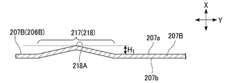
- the condensed water guide portion 217 protrudes toward the first surface 207a of the first flat surface portion 207B in a state of being bent in a direction intersecting the first surface 207a of the first flat surface portion 207B.
- the condensed water guide portion 217 extends continuously in the Z direction.
- the condensed water guide portion 217 is a convex portion 218 having a V-shaped cross-sectional shape when cut in a plane orthogonal to the Z direction and a uniform cross-sectional shape in the Z direction.
- the first surface 207a constituting the convex portion 218 projects in a V shape from the second surface 207b of the first flat surface portion 207B toward the first surface 207a.
- the second surface 207b constituting the convex portion 218 is a surface recessed in a V shape in the direction from the second surface 207b of the first flat surface portion 207B toward the first surface 207a.
- the fin pitch defining portion 215 is formed between the rear end portions of the flat tube insertion portions 209 adjacent to each other in the Z direction.
- the fin pitch defining portion 215 is arranged on one side of the uneven portion 211 in the Y direction.
- the fin pitch defining portion 215 is formed by bending a part of the fin main body 207 downward (one side in the Z direction).
- the fin pitch defining portion 215 is formed so as to project toward the first surface 207a.
- the fin pitch defining portion 215 is in contact with the second surface 207b of the fin 206 arranged on one side in the X direction, so that the pitch (fin pitch) of the fin 206 arranged in the X direction is set to a desired value.
- the shape of the fin pitch defining portion 215 can be, for example, an L-shape.
- FIGS. 28 to 30 a cutting step performed when manufacturing a plurality of fins 206 will be described.
- Cp indicates a position for cutting the structure shown in FIG. 28 (hereinafter, referred to as “cutting position Cp”) in the cutting step.
- the fin 206 having the above configuration is obtained by pressing a single plate material, cutting the cutting position Cp of the structure 220 (see FIG. 28) in which a plurality of fins 206 are connected in the left-right direction, and forming the plurality of fins 206. Manufactured by individualizing.
- the cutting device is used in the cutting step of the structure 220 performed after the manufacturing of the structure 220 in which the plate material (base material of the plurality of fins 206) is pressed and the plurality of fins 206 are connected.
- the second surface 207b corresponding to the cutting position Cp can be brought into contact with the upper surface of the stage. This makes it possible to arrange the structure 220 on the stage in a stable state, so that the structure 220 can be cut with high accuracy.
- the plurality of fins 206 so that the tip portions 209A of the flat tube insertion portions 209 constituting the fins 206 adjacent to each other face in the same direction.
- the rear end portions 209B of the flat tube insertion portions 209 constituting the pair of fins 206 adjacent to each other are arranged so as to face each other.
- the structure 225 may be used.
- the heat exchanger 205 having the above configuration is used as a condenser during the cooling operation to dissipate heat to the outside, and is used as an evaporator during the heating operation to absorb heat from the outside.
- the condensed water guide portion 217 formed in the communication portion 213 is composed of a convex portion 218 protruding from the first surface 207a constituting the first flat surface portion 207B. Therefore, the condensed water can be guided from the upper side to the lower side along the first and second surfaces 207a and 207b constituting the convex portion 218 while suppressing the obstruction of the flow of the condensed water. can. Further, by providing the convex portion 218 having the above configuration, it is possible to improve the strength of the communication portion 213.
- the first heat exchanger unit 201 By providing the above-mentioned heat exchanger 205 having excellent drainage of condensed water, the first heat exchanger unit 201 can be operated stably.
- FIGS. 31 and 32 The heat exchanger 230 of the sixth embodiment will be described with reference to FIGS. 31 and 32.
- FIG. 31 the same components as those of the structure shown in FIG. 23 are designated by the same reference numerals.
- FIGS. 31 and 32 the same components are designated by the same reference numerals.
- the heat exchanger 230 is configured in the same manner as the heat exchanger 205 except that it has a plurality of fins 231 instead of the plurality of fins 206 constituting the heat exchanger 205 of the fifth embodiment.
- the fin 231 is configured in the same manner as the fin 206 except that it has a communication portion 233 instead of the communication portion 213 constituting the fin 206.
- the communication portion 233 is configured in the same manner as the communication portion 213, except that it has a condensed water guide portion 235 instead of the condensed water guide portion 217 (convex portion 218) formed in the communication portion 213.
- the condensed water guide portion 235 protrudes from the first surface 207a constituting the first flat surface portion 207B, and has convex portions 238 (two as an example in FIGS. 31 and 32) arranged in the left-right direction and the Y direction. It is composed of a concave-convex portion 236 having a concave portion 239 (one in FIGS. 31 and 32 as an example) arranged between the convex portions 238 adjacent to each other.
- the uneven portion 236 is bent in a direction intersecting the first flat surface portion 207B, continuously extends in the Z direction, and has a cross-sectional shape when cut in a plane orthogonal to the Z direction (FIG. 32). In the case, the W-shape) is uniform in the Z direction.
- the uneven portion 236 having the above configuration As the condensed water guide portion 235, the obstruction of the flow of the condensed water is suppressed, and then along the first and second surfaces 207a and 207b constituting the uneven portion 236. , Condensed water can be guided from the upper side to the lower side. Further, by using the uneven portion 236 as the condensed water guide portion 235, the strength of the communication portion 233 can be improved, so that the fin 231 faces the flat tube insertion portion 209 in the left-right direction (Y direction). It is possible to suppress the occurrence of fin breakage in the portion (the portion where the strength of the fin 231 is weak).
- the condensed water guide portion 235 by forming the condensed water guide portion 235 with the uneven portion 236, the surface area of the condensed water guide portion 235 is increased and the air side is increased as compared with the case where the condensed water guide portion 217 is composed of one convex portion 218. It is possible to improve the heat transfer coefficient of. As a result, the heat exchange efficiency between the condensed water guide portion 235 and the air can be improved.
- FIG. 33 the same components as those of the structure shown in FIG. 23 are designated by the same reference numerals.
- FIGS. 33 and 34 the same components are designated by the same reference numerals.
- the heat exchanger 240 is configured in the same manner as the heat exchanger 205 except that it has a plurality of fins 241 instead of the plurality of fins 206 constituting the heat exchanger 205 of the fifth embodiment.
- the fin 241 is configured in the same manner as the fin 206 except that it has a communication portion 243 instead of the communication portion 213 constituting the fin 206.
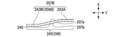
- the communication portion 243 has a condensed water guide portion 245 extending continuously in the Z direction.
- the condensed water guide portion 245 is a step portion 246, and has a first portion 243A and a second portion 243B constituting the first flat surface portion 207B, a connection portion 248, and a condensed water guide portion 245.
- the first portion 243A is a portion of the first flat surface portion 207B arranged on the one end portion 206A side of the fin main body 207, and extends continuously in the Z direction.
- the second portion 243B constitutes the other end portion 206B of the fin 206 in the first flat surface portion 207B, and extends continuously in the Z direction.
- the second portion 243B is arranged at a position offset to the other side in the X direction from the position where the first portion 243A is formed.
- the first and second surfaces 207a and 207b constituting the second portion 243B are parallel to the first and second surfaces 207a and 207b constituting the first portion 243A.
- the connecting portion 248 is arranged between the first portion 243A and the second portion 243B, and extends continuously in the Z direction. One end of the connection 248 is connected to the first portion 243A. The other end of the connection 248 is connected to the second portion 243B.
- the first and second surfaces 207a and 207b constituting the connecting portion 248 are inclined with respect to the first and second surfaces 207a and 207b constituting the first and second portions 243A and 243B.
- the condensed water guide portion 245 (step portion 246) has a configuration in which a step is formed in the X direction.
- the condensed water guide portion 245 by forming the condensed water guide portion 245 with the step portion 246, it is possible to improve the heat transfer coefficient on the air side while increasing the surface area of the condensed water guide portion 245. As a result, the heat exchange efficiency between the condensed water guide portion 245 and the air can be improved.
- FIG. 35 the same components as those of the structure shown in FIG. 23 are designated by the same reference numerals.
- FIGS. 35 to 37 the same components are designated by the same reference numerals.
- the heat exchanger 250 is configured in the same manner as the heat exchanger 205 except that it has a plurality of fins 251 instead of the plurality of fins 206 constituting the heat exchanger 205 of the fifth embodiment.
- the fin 251 is provided with a pedestal portion 252 protruding toward the first surface 207a of the first flat surface portion 207B around the flat tube insertion portion 209, and is X with reference to the first surface 207a of the first flat surface portion 207B.
- the fin 206 is configured in the same manner as the fin 206 described above, except that the convex portion 218 and the pedestal portion 252 are connected to each other.
- the height H 1 of the convex portion 218 and the height H 2 of the pedestal portion 252 in the X direction are made equal to each other, and the convex portion 218 and the pedestal portion 252 are connected at the position of the tip 218A of the convex portion 218.
- the first flat surface portion 207B is not arranged between the pedestal portion 252 and the convex portion 218 in the Y direction.
- the first flat surface portion 207B can be discontinuous in the Z direction between the pedestal portion 252 and the convex portion 218, so that the fin breakage between the pedestal portion 252 and the convex portion 218 can be caused. The occurrence can be suppressed.
- the convex portion 218 condensed water guide portion 217) and the pedestal portion 252 are connected has been described as an example, but for example, the convex portion constituting the uneven portion 236 has been described.
- the portion 238 and the pedestal portion 252 may be connected to each other.
- the heat exchanger 260 is configured in the same manner as the heat exchanger 250 except that it has fins 261 instead of the fins 251 constituting the heat exchanger 250 of the eighth embodiment.
- the fin 261 is configured in the same manner as the fin 251 except that it has a pedestal portion 263 instead of the pedestal portion 252 constituting the fin 251.
- the pedestal portion 263 is configured in the same manner as the pedestal portion 252, except that the upper side of the portion connected to the convex portion 218 is inclined diagonally downward from the pedestal portion 263 toward the convex portion 218.
- the heat exchanger 270 is configured in the same manner as the heat exchanger 260 except that it has fins 271 in place of the fins 261 constituting the heat exchanger 260 according to the first modification of the eighth embodiment. ..
- the fin 271 is configured in the same manner as the fin 261 except that it has a pedestal portion 273 instead of the pedestal portion 263 constituting the fin 261.
- the pedestal portion 273 is configured in the same manner as the pedestal portion 263 except that the upper side and the lower side of the portion connected to the convex portion 218 are inclined diagonally downward from the pedestal portion 273 toward the convex portion 218.
- FIG. 40 the solid arrow indicates the direction in which the refrigerant flows during the heating operation, and the dotted arrow indicates the direction in which the refrigerant flows during the cooling operation.
- the same components as those of the structure shown in FIG. 21 are designated by the same reference numerals.
- the refrigeration cycle device 280 replaces the first and second heat exchanger units 201 and 203 constituting the refrigeration cycle device 200 of the second embodiment with the first and second heat exchanger units 281, 283. It is configured in the same manner as the refrigerating cycle apparatus 200 except that it has.
- the first heat exchanger unit 281 is configured in the same manner as the first heat exchanger unit 201 except that it has a heat exchanger 285 instead of the heat exchanger 205.
- the second heat exchanger unit 283 is configured in the same manner as the second heat exchanger unit 203 except that it has a heat exchanger 285 instead of the heat exchanger 205.
- the Z direction indicates the first direction.
- the X direction indicates the extending direction of the flat tube 41 orthogonal to the Z direction.
- the Y direction is the second direction orthogonal to the X direction and the Z direction (the width direction of the flat tube 41 when the flat tube 41 is attached to the fin 290), and P is the direction in which air flows (the direction in which air flows).
- direction P is the direction in which air flows (the direction in which air flows).
- the heat exchanger 285 is configured in the same manner as the heat exchanger 205 except that it has a plurality of fins 290 instead of the plurality of fins 206 constituting the heat exchanger 205 described in the second embodiment.
- FIGS. 41 to 46 A plurality of fins 290 will be described with reference to FIGS. 41 to 46.
- FIGS. 43 to 46 the same components as those of the structures shown in FIGS. 41 and 42 are designated by the same reference numerals.
- the plurality of fins 290 are arranged at a predetermined pitch in the X direction.
- the fin 290 has a fin main body 291 instead of the fin main body 207 constituting the fin 206 described in the fifth embodiment, and further has a plurality of heat conductive portions 305, a plurality of first fin pitch defining portions 307, and a plurality of first fin pitch defining portions 307. It is configured in the same manner as the fin 206 except that it has a plurality of second fin pitch defining portions 308.
- the fin body 291 has a plate shape and extends in the Z direction.
- the fin body 291 has first and second surfaces 291a and 291b arranged in the X direction.
- the first surface 291a is arranged so as to face the doorway header 35.
- the second surface 291b is a surface arranged on the opposite side of the first surface 291a.
- the second surface 291b is arranged so as to face the folding header 37.
- the fin body 291 has a plate shape and has a communication portion 303 extending in the Z direction.
- the heat conduction portion 305 is formed around the flat tube insertion portion 209 so as to rise toward the first surface 291a.
- the heat conductive portion 305 protrudes in the X direction.
- the inner peripheral surface 305a of the heat conductive portion 305 comes into surface contact with the outer peripheral surface 41b of the flat tube 41.
- the height of the heat conductive portion 305 in the X direction is set so that when a plurality of fins 290 are arranged in the X direction, they do not come into contact with the fins 290 arranged on the first surface 291a side.
- the heat conductive portion 305 By having the heat conductive portion 305 having such a configuration, it is possible to increase the contact area between the flat tube 41 and the plurality of fins 290. Thereby, the thermal conductivity between the flat tube 41 and the plurality of fins 290 can be improved. Further, the height of the heat conductive portion 305 in the X direction is set to a height at which the heat conductive portion 305 does not abut on the fins 290 arranged on the first surface 291a side, so that the first and second fin pitches are defined. After defining the fin pitch by using the portions 307 and 308, the thermal conductivity between the flat tube 41 and the fin 290 can be improved.
- the first fin pitch defining portion 307 is formed between the rear end portions of the flat tube insertion portions 209 adjacent to each other in the Z direction.
- the first fin pitch defining portion 307 is arranged on one side of the uneven portion 211 in the Y direction.
- the first fin pitch defining portion 307 is formed by bending a part of the fin main body 291 downward (one side in the Z direction). The first fin pitch defining portion 307 is formed so as to project toward the first surface 291a. The first fin pitch defining portion 307 abuts on the second surface 291b of the fins 290 arranged on one side in the X direction, thereby adjusting the pitch (fin pitch) of the fins 290 arranged in the X direction. Keep at the desired value.
- the first fin pitch defining portion 307 is preferably L-shaped, for example.
- the first fin pitch defining portion 307 is a first fin pitch defining portion.
- the probability that 307 will come into contact with the second surface 291b can be increased.
- the first fin pitch defining portion 307 into an L shape it is possible to increase the contact area between the first fin pitch defining portion 307 and the second surface 291b, so that the fin pitch can be increased. It can be maintained stably.
- the second fin pitch defining portion 308 is a flat tube located above the first fin pitch defining portion 307 of the two flat tube inserting portions 209 sandwiching the first fin pitch defining portion 307 in the Z direction. It is arranged around the insertion portion 209. Specifically, the second fin pitch defining portion 308 is located below the flat tube insertion portion 209 and near the tip portion 209A (at the rear end portion side of the flat tube insertion portion 209 rather than the tip portion 209A). It is arranged on the tip portion 209A side). The second fin pitch defining portion 308 is formed by bending a part of the fin main body 291 downward (one side in the Z direction) and projecting it toward the first surface 291a.
- the second fin pitch defining portion 308 is brought into contact with the second surface 291b of the fin 290 arranged on the other side in the X direction, so that the second fin pitch defining portion 308 and the first fin pitch defining portion 307 described above are X.
- the pitch (fin pitch) of the fins 290 arranged in the direction is kept at a desired value.
- the protrusion amounts of the first and second fin pitch defining portions 307 and 308 in the X direction are equal, and the fin pitch is set to a size that can be maintained at a desired value.
- the second fin pitch defining portion 308 is preferably L-shaped, for example. By forming the second fin pitch defining portion 308 into an L shape, the same effect as that of the first fin pitch defining portion 307 having the L shape described above can be obtained.
- the heat exchanger 285 having the above configuration is used as a condenser during the cooling operation to dissipate heat to the outside, and is used as an evaporator during the heating operation to absorb heat from the outside.
- the first and second fin pitch defining portions 307 and 308 can be arranged at positions separated from each other in the Z direction and the Y direction. Thereby, the fin pitches of the plurality of fins 290 arranged in the X direction can be stably defined.
- the outer shape of the second end 41E of the flat tube 41 is circular or elliptical, and the shape of the tip 209A of the flat tube insertion portion 209 accommodating the second end 41E is the shape of the flat tube 41.
- the fin pitch can be stably defined while suppressing the pressure loss of air, and the thermal conductivity between the flat tube 41 and the fin 290 can be improved. Further, by not forming the first and second fin pitch defining portions 307 and 308 in the communication portion 303 extending in the first direction (Z direction), the condensed water discharged in the first direction (Z direction) is discharged. Since the first and second fin pitch defining portions 307 and 308 do not obstruct the flow, good drainage can be maintained.
- a part of the fin body 291 is bent downward to form the first fin pitch defining portion 307, and the two flat tube inserting portions 209 sandwiching the first fin pitch defining portion 307 in the Z direction.
- the positions defining the fin pitch are evenly spaced in the Z direction. Since it is possible to arrange the fin pitch in a stable manner, the fin pitch can be stably specified.
- the first heat exchanger unit 281 by providing the above-mentioned heat exchanger 285, the performance of the first heat exchanger unit 281 is improved and the first heat exchanger unit 281 is stabilized. Can be operated.
- the second heat exchanger unit 283 including the heat exchanger 285 can also obtain the same effect as the first heat exchanger unit 281.
- the fin 320 according to the modified example of the ninth embodiment will be described with reference to FIG. 47.
- FIG. 47 the same components as those of the structure shown in FIG. 42 are designated by the same reference numerals.
- the fin 320 forms a first fin pitch defining portion 307 by bending a part of the fin main body 291 upward, and also has two flat tube insertion portions 209 sandwiching the first fin pitch defining portion 307 in the Z direction.
- the configuration is the same as that of the fin 290 described above, except that the second fin pitch defining portion 308 is formed around the flat tube inserting portion 209 located on the lower side of the first fin pitch defining portion 307. Has been done.
- the first fin pitch defining portion 307 is formed by bending a part of the fin main body 291 upward, and the two flat tube inserting portions 209 sandwiching the first fin pitch defining portion 307 in the Z direction are formed.
- the second fin pitch defining portion 308 around the flat tube inserting portion 209 located on the lower side of the first fin pitch defining portion 307, the position defining the fin pitch is set in the Z direction and the like. It is possible to arrange them at intervals. Thereby, the fin pitch can be stably defined.
- the heat exchangers are 27, 60, 70, 80, 90, 100, 110, 120, 130, 140, 150, 160, 170, 180, 190, and the outer shape is flat and one direction (X direction).
- the plurality of fins 42 arranged in the extending direction (X direction) of the flat tube 41 and one end 41B of the plurality of flat tubes 41 are arranged inward.
- a header 43 connected to a flat tube 41 and through which the refrigerant flows is provided, and the header 43 has a tubular shape extending in the vertical direction (Z direction), and a header main body 45 for partitioning a columnar internal space 53.
- the refrigerant is accommodated in the header body 45, extends in the vertical direction (Z direction), and the refrigerant can flow in the upper end portion and the lower end portion of the internal space 53.
- a partition plate 47 that divides the internal space 53 into a first space 54 and a second space 55 in which one end 41B of the plurality of flat tubes 41 is arranged, and an arrangement under the first space 54. It has nozzle portions 49, 62 including outlets 49A, 62A, which blow out the refrigerant supplied from the outside of the header 43 toward the bottom surface 45a (first bottom surface 45aa) of the header body 45. Refrigerator flow portions 54A, which are a part of the first space 54, are formed on both sides of the nozzle portions 49 and 62 in the width direction (Y direction).
- the refrigerant blown out from the outlets 49A, 62A collides with the bottom surface 45a (first bottom surface 45aa) of the header body 45, and is in the width direction (Y direction). It is possible to reduce the difference in the state of the refrigerant in. As a result, the refrigerant having a small difference in state in the width direction (Y direction) moves from the first space 54 toward the second space 55 (the space in which one end 41B of the plurality of flat tubes 41 is arranged).
- a circulating flow of the refrigerant (a flow that descends from the first space 54 and rises from the second space 55) flows in the header 43 without depending on the flow rate of the refrigerant introduced into the header 43.
- a plurality of flow paths 41A formed in the width direction (Y direction) of each flat tube 41 while suppressing the complexity of the manufacturing process and suppressing the bias of the refrigerant distribution to each flat tube 41. It is also possible to suppress the bias of the refrigerant distribution with respect to the above.
- the heat exchangers 70, 80, 100, 120, 150, 180, 190 according to the second aspect are the heat exchangers 70, 80, 100, 120, 150, 180, 190 of (1).
- the bottom surface 45a of the header body 45 has a first bottom surface 45aa for partitioning the first space 54 and a second bottom surface 45ab for partitioning the second space 55.
- a first refrigerant guide 73 may be provided on the bottom surface 45aa and has a first guide surface 73a for guiding the refrigerant in the direction from the first space 54 toward the second space 55.
- the refrigerant blown out from the outlets 49A and 62A of the nozzle portions 49 and 62 is guided to the second space 55 and the second space is provided. It is possible to reduce the difference in the state of the refrigerant in the width direction (Y direction) by causing the refrigerant to collide with the inner wall surface 45b of the header body 45 that partitions the 55. Further, when the refrigerant is a gas-liquid two-phase refrigerant and the flow rate of the refrigerant introduced into the header main body 45 is small, the refrigerant is gas-liquid separated in the first space 54, and the first space 54 is in the gas phase. It is possible to suppress the rise of the refrigerant. That is, it is possible to prevent the refrigerant circulation flow from becoming difficult to form in the header body 45.
- the heat exchangers 70, 80, 100, 120, 150, 180, 190 according to the third aspect are the heat exchangers 70, 80, 100, 120, 150, 180, 190 of (2).
- the first guide surface 73a may be a concave curved surface recessed in a direction away from the lower end portion of the partition plate 47.
- the refrigerant can be smoothly guided from the first space 54 to the second space 55. can.
- the heat exchangers 90, 100, 180, 190 according to the fourth aspect are the heat exchangers 90, 100, 180, 190 according to any one of (1) to (3).
- the bottom surface 45a of the header body 45 has a first bottom surface 45aa for partitioning the first space 54 and a second bottom surface 45ab for partitioning the second space 55.
- a second refrigerant guide 93 which is provided on the bottom surface 45ab and has a second guide surface 93a for guiding the refrigerant in the direction from the lower side to the upper side of the second space 55, may be provided.
- the refrigerant having a small difference in state in the width direction generated by colliding with the first bottom surface 45aa of the header main body 45 can be used in the second space. It can be guided in the direction from the lower side of the 55 to the upper side.
- the heat exchangers 90, 100, 180, 190 according to the fifth aspect are the heat exchangers 90, 100, 180, 190 of (4), and the second guide surface 93a is the partition. It may be a concave curved surface recessed in a direction away from the lower end portion of the plate 47.
- the refrigerant having a small difference in state in the width direction (Y direction) can be used in the second space 55. It can be easily guided from the bottom to the top.
- the heat exchanger 80 according to the sixth aspect is the heat exchanger 80 according to any one of (1) to (5), and the header of the lower end of the partition plate 47.
- a third refrigerant guide provided in a portion upward from the bottom surface 45a of the main body 45 and including a third guide surface 83a for guiding the refrigerant in a direction from the first space 54 toward the second space 55.
- the unit 83 may be provided.
- the refrigerant can be guided in the direction from the first space 54 to the second space 55 by the third guide surface 83a.
- the heat exchanger 80 according to the seventh aspect is the heat exchanger 80 of (6), and the third refrigerant guide portion 83 extends in the width direction (Y direction) of the partition plate 47. It may be a columnar member.
- the third guide surface 83a (outer peripheral surface of the columnar member) allows the first space 54 to be the third.
- the refrigerant can be guided in the direction toward the space 55 of 2.
- the heat exchangers 27, 60, 70, 80, 90, 100, 110, 120, 130, 140, 150, 160, 170, 180, 190 according to the eighth aspect are (1) to (7).
- the heat exchangers 27,60,70,80,90,100,110,120,130,140,150,160,170,180,190 according to any one of the above the nozzle portion 49, 62 may be arranged at a position lower than 1/2 of the height of the header body.
- the bottom surface of the header main body 45 (first bottom surface) is arranged from the outlets 49A, 62A of the nozzle portions 49, 62. Since the distance to 45aa) becomes too long, the flow of the refrigerant blown out from the outlets 49A and 62A may be attenuated, making it difficult to form a circulating flow of the refrigerant in the header 43. Therefore, by arranging the nozzle portions 49, 62 at a position lower than 1/2 of the height H of the header body 45, the distance from the outlets 49A, 62A to the bottom surface of the header body 45 (first bottom surface 45aa). Is possible to shorten the length, so that it becomes easy to form a circulating flow of the refrigerant in the header 43.
- the heat exchangers 27, 60, 70, 80, 90, 100, 110, 120, 130, 140, 150, 160, 170, 180, 190 according to the ninth aspect are (1) to (7).
- the heat exchangers 27,60,70,80,90,100,110,120,130,140,150,160,170,180,190 according to any one of the above the nozzle portion 49, The 62 may be arranged between the flat tube 41F arranged at the bottom and the flat tube 41S arranged second from the bottom among the plurality of flat tubes 41.
- the circulation flow of the refrigerant in the header 43 can be prevented. It can be easily formed. Further, when the heat exchangers 27, 60, 70, 80, 90, 100, 110, 120, 130, 140, 150, 160, 170, 180, 190 are used as the condenser, the heat exchangers are used via a plurality of flat tubes 41. The refrigerant (liquid phase refrigerant) flowing into the header 43 can be easily discharged to the outside of the header.
- the heat exchangers 110, 120, 130, 190 according to the tenth aspect are the heat exchangers 110, 120, 130, 190 according to any one of (1) to (9).
- one end of the plurality of flat tubes 41 is arranged so as to face the partition plate 47, and the flat tube 41 is arranged at the bottom of the plurality of flat tubes 41.
- the distance Ds1 from one end of the pipe 41F to the partition plate 47 may be longer than the distance Ds2 from one end of the other flat pipes 41, 41S to the partition plate 47.
- the distance Ds1 from one end 41F of the flat pipe 41F arranged at the bottom to the partition plate 47 is the distance Ds1 from one end 41a of the other flat pipe 41 to the partition plate 47.
- Ds2 the distance Ds1 from one end 41a of the other flat pipe 41 to the partition plate 47.
- the heat exchangers 110 and 120 are the heat exchangers 110 and 120 of (10), and one end of the flat tube 41F arranged at the bottom thereof is the other flat.
- the pipes 41 and 41S may be arranged so as to be retracted from the position of one end of the pipes 41 and 41S in the direction from the first space 54 toward the second space 55.
- one end 41F of the flat tube 41F arranged at the bottom is placed at a position recessed from the position of one end 41a of the other flat tube 41 in the direction from the first space 54 toward the second space 55.
- the cross-sectional area of the refrigerant flow path formed between one end 41F of the flat pipe 41F arranged at the bottom and the partition plate 47 can be increased.
- the heat exchangers 130 and 190 according to the twelfth aspect are the heat exchangers 130 and 190 according to any one of (10) and (11), and are arranged at the bottom thereof.
- the lower end portion 133A of the partition plate 133 facing one end of the flat tube 41F may be arranged at a position deviated from the second space 55 toward the first space 54.
- the lower end portion 133A of the partition plate 133 facing the one end 41F of the flat pipe 41F arranged at the bottom is directed from the second space 55 toward the first space 54.
- the heat exchangers 140, 150, 160, 170, 180, 190 according to the thirteenth aspect are the heat exchangers 140, 150, 160, according to any one of (1) to (12). 170, 180, 190, which are provided on the inner wall surface 45b of the header body 45 for partitioning the second space 55, and the flat tube 41F arranged at the bottom of the plurality of flat tubes 41. Even if the rectifying member 143, 163, 173 is provided below the one end 41B and rectifies the refrigerant from the bottom surface 45a of the header body 45 toward one end of the flat tube 41F arranged at the bottom. good.
- the heat exchangers 140 and 150 according to the fourteenth aspect are the heat exchangers 140 and 150 of (13), and the rectifying member 143 is one of the flat tubes 41F arranged at the bottom. Is arranged at a position away from the end portion 41B of the header body 45, extends from the inner wall surface 45b of the header body 45 toward the partition plate 47, and the amount of protrusion from the inner wall surface 45b of the header body 45 is the one end portion 41B. It may be a baffle plate 145 equal to the protrusion amount of.
- the baffle plate 145 having the above configuration as the rectifying member 143 the flow of the refrigerant is separated in the front stage of one end 41B of the flat tube 41F arranged at the bottom, and one It is possible to rectify the flow of the refrigerant at the end of the flat tube 41F arranged at the bottom.
- the liquid phase refrigerant can be easily supplied to the flat tube 41F, which may be difficult for the liquid phase refrigerant to flow in due to the influence of peeling (contraction) in the past, and as a result, each flat tube 41 can be easily supplied. Refrigerant distribution to can be equalized.
- the heat exchanger 160 is the heat exchanger 160 of (13), and the rectifying member 163 is one end 41B of the flat tube 41F arranged at the bottom. It is arranged below the one end 41B so as to come into contact with the lower surface of the header body, extends from the inner wall surface 45b of the header body 45 toward the partition plate 47, and protrudes from the inner wall surface 45b of the header body 45.
- the block 164 may have an amount equal to the protrusion amount of the one end portion 41B.
- the block 164 having the above configuration as the rectifying member 163, the flow of the refrigerant is separated at the front stage of one end 41B of the flat tube 41F arranged at the bottom, and the first It is possible to rectify the flow of the refrigerant at the end of the flat tube 41F arranged below.
- the liquid phase refrigerant can be easily supplied to the flat tube 41F, which may be difficult for the liquid phase refrigerant to flow in due to the influence of peeling (contraction) in the past, and as a result, each flat tube 41 can be easily supplied. Refrigerant distribution to can be equalized.
- the heat exchanger 170 according to the sixteenth aspect is the heat exchanger 170 of (15), and the block 174 is formed on the partition plate 47 side and is curved to guide the flow of the refrigerant upward. It may have a surface 174a.
- the refrigerant can be guided above the second space 55 without the flow being separated.
- the heat exchangers 27, 60, 70, 80, 90, 100, 110, 120, 130, 140, 150, 160, 170, 180, 190 according to the seventeenth aspect are (1) to (16).
- the first space A perforated plate provided between the header body 45 for partitioning the 54 and the partition plates 47 and 133, and arranged in a portion of the first space 54 located above the nozzle portions 49 and 62. 51 may be provided.
- the perforated plate 51 having such a configuration, it is possible to suppress the movement of the gas (gas refrigerant) that flows backward from the lower side to the upper side of the first space 54, and thus the inside of the header 43. It becomes easy to form a circulating flow of the refrigerant.
- the heat exchanger 27 according to the eighteenth aspect is the heat exchanger 27 according to any one of (1) to (17), and the outlet 49A is a circular hole.
- the partition plate 47 is arranged on one side in the width direction (Y direction), and the lower end thereof reaches the bottom surface 45a of the header body 45 at one lower end portion 47A and the other side in the width direction (Y direction).
- a notch portion that is arranged and is formed between the other lower end portion 47B whose lower end reaches the bottom surface 45a of the header body 45, the one lower end portion 47A, and the other lower end portion 47B, and through which the refrigerant flows. 47C and may have.
- the refrigerant is introduced from the first space 54 through the notch 47C located between the one lower end 47A and the other lower end 47B. It is distributed to the space 55 of 2. At this time, the lower ends 47A and 47B can prevent the refrigerant from flowing back from the second space 55 to the first space 54.
- the heat exchanger 60 according to the nineteenth aspect is the heat exchanger 60 according to any one of (1) to (17), and the outlet 62A is the nozzle portion 62. It has a groove shape extending in the width direction (Y direction), and the total value of the widths W2 of the two refrigerant flow portions 54A arranged on both sides of the nozzle portion 62 in the width direction (Y direction) is the nozzle portion. It may be smaller than the value of the width W1 of 62.
- the heat exchanger unit (first and second heat exchanger units 18, 23) according to the twentieth aspect is the heat exchanger according to any one of (1) to (19).
- the heat exchanger units By having the heat exchangers 27, 60, 70, 80, 90, 100, 110, 120, 130, 140, 150, 160, 170, 180, 190 having the above configuration, the heat exchanger units (first and first) The heat exchange efficiency of the second heat exchanger units 18, 23) can be improved.
- the refrigeration cycle device 10 includes the heat exchanger unit (1st and 2nd heat exchanger units 18, 23) of (20).
- the heat exchanger units first and second heat exchanger units 18, 23
- the heat exchange efficiency of the refrigeration cycle device 10 can be improved.
- the heat exchanger 205, 230, 240, 250, 260, 270 is a heat exchanger 205, 230, 240, 250, 260, 270 that exchanges heat between air and a refrigerant.
- the outer shape is flat, and the flow path 41A through which the refrigerant flows is formed inside, and the first end portion 41D arranged on one side in the width direction and the second end portion 41D arranged on the other side in the width direction are arranged.
- a fin body 207 including a surface 207a of 1 and a second surface 207b arranged on the opposite side of the first surface 207a, and formed on the fin body 207 and in the extending direction (X direction).
- a plurality of pieces are arranged at intervals in the vertical direction (Z direction) orthogonal to the vertical direction, and from one side of the horizontal direction (Y direction) orthogonal to the vertical direction (Z direction) and the extension direction (X direction).
- a flat tube insertion portion 209 extending to the other side and accommodating the flat tube 41 inserted from the second end portion 41E side, and the other side in the left-right direction (Y direction) from the plurality of the flat tube insertion portions 209.
- Each of the communication portions 213, 233, 243 which are arranged on the side and extend continuously in the vertical direction (Z direction), are provided with the communication portions 213, 233, 243 in the vertical direction (Z direction) and the communication portion.
- the communication portion 213, 233, 243 includes a first flat surface portion 207B parallel to the left-right direction (Y direction), and is bent in a direction intersecting with the first flat surface portion 207B to form the communication portion 213, 233, 243.
- Condensed water guide that extends continuously in the vertical direction (Z direction) and has a uniform cross-sectional shape in the vertical direction (Z direction) when cut in a plane orthogonal to the vertical direction (Z direction). Parts 217, 235 and 245 are formed.
- the condensed water guide units 217, 235 and 245 By having the condensed water guide units 217, 235 and 245 having such a configuration, the first and second condensed water guide units 217, 235 and 245 are configured while suppressing the obstruction of the flow of the condensed water. Condensed water can be guided in the direction from the upper side to the lower side along the surfaces 207a and 207b. Further, by providing the condensed water guide portions 217, 235 and 245 having the above configuration, it is possible to improve the strength of the communication portions 213, 233, 243.
- the fins 206, 231,241, 251,261 are located in the portion facing the flat tube insertion portion 209 in the left-right direction (Y direction) (the portion where the strength of the fins 206, 231,241, 251,261 is weak). It is possible to suppress the occurrence of breakage. Further, by having the condensed water guide unit 217, 235, 245 having the above configuration, it is possible to improve the thermal conductivity on the air side while increasing the surface area of the condensed water guide unit 217, 235, 245. .. As a result, the heat exchange efficiency between the condensed water guide unit 217, 235, 245 and the air can be improved.
- the heat exchanger 205 according to the 23rd aspect is the heat exchanger 205 of (22), and the condensed water guide portion 217 is the first surface constituting the first flat surface portion 207B. It may be a convex portion 218 protruding from 207a.
- the condensed water guide portion 217 formed in the communication portion 213 with the convex portion 218 protruding from the first surface 207a constituting the first flat surface portion 207B, the flow of the condensed water is hindered. After restraining, the condensed water can be guided in the direction from the upper side to the lower side along the first and second surfaces 207a and 207b constituting the convex portion 218. Further, by providing the convex portion 218 having the above configuration, it is possible to improve the strength of the communication portion 213.
- the heat exchanger 230 according to the 24th aspect is the heat exchanger 230 of (22), and the condensed water guide portion 235 is the first surface portion constituting the first flat surface portion 207B.
- Concavities and convexities having a plurality of convex portions 218 protruding from the 207a and arranged in the left-right direction (Y direction) and concave portions 239 arranged between the convex portions 218 adjacent to each other in the left-right direction (Y direction). It may be part 236.
- the uneven portion 236 having such a configuration as the condensed water guide portion 235 By using the uneven portion 236 having such a configuration as the condensed water guide portion 235, the obstruction of the flow of the condensed water is suppressed, and then the first and second surfaces 207a and 207b constituting the uneven portion 236 are formed. Condensed water can be guided along the direction from the upper side to the lower side. Further, by using the uneven portion 236 as the condensed water guide portion 235, the strength of the communication portion 233 can be improved, so that the fin 231 faces the flat tube insertion portion 209 in the left-right direction (Y direction). It is possible to suppress the occurrence of fin breakage in the portion (the portion where the strength of the fin 231 is weak).
- the condensed water guide portion 235 by forming the condensed water guide portion 235 with the uneven portion 236, the surface area of the condensed water guide portion 235 is increased and the air side is increased as compared with the case where the condensed water guide portion 217 is composed of one convex portion 218. It is possible to improve the thermal conductivity of. As a result, the heat exchange efficiency between the condensed water guide portion 235 and the air can be improved.
- the heat exchanger 250 according to the 25th aspect is the heat exchanger 250 of (23) or (24), and the flat tube insertion portion 209 is located on the other side in the left-right direction (Y direction).
- the fin body 207 is arranged and has a tip portion 209A accommodating the second end portion 41E, and the fin body 207 is arranged between the tip portions 209A adjacent to each other in the vertical direction (Z direction).
- the second flat surface portion 207A parallel to the vertical direction (Z direction) and the left-right direction (Y direction) is provided, and the second flat surface portion 207A of the second flat surface portion 207A is provided around the flat tube insertion portion 209.
- a pedestal portion 252 protruding toward the surface 207a of 1 is arranged, and the tip 218A of the convex portion 218 in the extending direction (X direction) with respect to the first surface 207a of the second flat surface portion 207A.
- the height H 1 of the pedestal portion 252 is equal to the height H 2 of the pedestal portion 252 in the extending direction (X direction) with respect to the first surface 207a of the second flat surface portion 207A, and the height H 1 of the convex portion 218.
- the convex portion 218 and the pedestal portion 252 may be connected at the position of the tip 218A.
- the height H 1 of the convex portion 218 and the height H 2 of the pedestal portion 252 in the X direction are made equal to each other, and the convex portion 218 and the pedestal portion 252 are connected at the position of the tip 218A of the convex portion 218.
- the first flat surface portion 207B is not arranged between the pedestal portion 252 and the convex portion 218 in the left-right direction (Y direction).
- the first flat surface portion 207B can be discontinuous in the vertical direction (Z direction) between the pedestal portion 252 and the convex portion 218, and thus between the pedestal portion 252 and the convex portion 218. It is possible to suppress the occurrence of fin breakage in.
- the heat exchanger 260 according to the 26th aspect is the heat exchanger 260 of (25), and the upper side of the portion of the pedestal portion 263 connected to the condensed water guide portion 217 is the above. It may be inclined diagonally downward from the pedestal portion 263 toward the condensed water guide portion 217.
- the heat exchanger 240 according to the 27th aspect is the heat exchanger 240 of (22), and the first flat surface portion 207B is the left-right direction (Y direction) of the condensed water guide portion 245.
- the first portion 243A which is arranged on one side and extends in the vertical direction (Z direction) and the condensate water guide portion 245 which is arranged on the other side of the horizontal direction (Y direction) and is arranged in the vertical direction (Z direction).
- a second portion 243B arranged at a position different from the first portion 243A in the extending direction (X direction), and the condensed water guide portion 245 is the first portion. It may be a stepped portion 246 composed of a portion 243A, the second portion 243B, and a connecting portion 248 connecting the first portion 243A and the second portion 243B.
- the stepped portion 246 having such a configuration as the condensed water guiding portion 245 By using the stepped portion 246 having such a configuration as the condensed water guiding portion 245, the obstruction of the flow of the condensed water is suppressed, and then the first and second surfaces 207a and 207b constituting the connecting portion 248 are formed. Condensed water can be guided along the direction from the upper side to the lower side. Further, by forming the condensed water guide portion 245 with the step portion 246, it is possible to improve the strength of the communication portion 243. Therefore, among the fins 241 in the left-right direction (Y direction), the flat tube insertion portion 209 It is possible to suppress the occurrence of fin breakage in the facing portions (the portions where the strength of the fins 241 is weak).
- the condensed water guide portion 245 by forming the condensed water guide portion 245 with the step portion 246, it is possible to improve the thermal conductivity on the air side while increasing the surface area of the condensed water guide portion 245. As a result, the heat exchange efficiency between the condensed water guide portion 245 and the air can be improved.
- the heat exchanger 205, 230, 240, 250, 260 is the heat exchanger 205, 230, 240, 250, according to any one of (22) to (27).
- the fins 206, 231,241, 251,261 are one end 206A arranged on one side in the left-right direction (Y direction) and the other end arranged on the other side in the left-right direction.
- the condensed water guide portions 217, 235 and 245 are arranged on the one end 206A side of the other end 206B, and the one end 206A and The second surface 207b constituting the other end 206B may be arranged on the same plane.
- the cutting step of the structure 220 performed after the manufacture of the 220 the second surface 207b corresponding to the cutting position Cp is brought into contact with the upper surface of the stage of the cutting device, and the structure 220 is placed on the stage in a stable state. It becomes possible.
- the structure 220 can be cut with high accuracy. That is, the machining accuracy of the fins 206, 231,241, 251,261 can be improved.
- the heat exchanger unit (first and second heat exchanger units 201, 203) according to the 29th aspect is the heat exchanger 205 according to any one of (22) to (28). , 230, 240, 250, 260 and blowers (first and second blowers 26, 32) for sending air to the heat exchangers 205, 230, 240, 250, 260.
- the heat exchanger units 205, 230, 240, 250, 260 described above are provided in the heat exchanger units (first and second heat exchanger units 201, 203), whereby the heat exchanger unit (first). And the second heat exchanger unit 201, 203) can be operated stably.
- the refrigeration cycle device 200 includes the heat exchanger unit (first and second heat exchanger units 201, 203) of (29).
- the refrigeration cycle apparatus 200 can be operated stably.
- the heat exchanger 285 has a flat outer shape, and a flow path 41A through which a refrigerant flows is formed inside, and is arranged on one side in the width direction (Y direction).
- a plurality of flat pipes 41 having an end portion 41D of 1 and a second end portion 41E arranged on the other side in the width direction, and the flat pipe 41 extending in a state of accommodating the plurality of flat pipes 41.
- a first surface having a plurality of fins 290 arranged in a direction (X direction) at a predetermined pitch, and the plurality of fins 290 having a plate shape and arranged in the extending direction (X direction).
- the fin body 291 including the 291a and the second surface 291b arranged on the opposite side of the first surface 291a, and the fin body 291 are formed and orthogonal to the extending direction (X direction).
- a plurality of arrangements are arranged at intervals in the first direction (Z direction), and in a second direction (Y direction) orthogonal to the first direction (Z direction) and the extension direction (X direction).
- a flat tube insertion portion 209 extending from one side to the other side and accommodating the flat tube 41 inserted from the second end portion 41E side, and the second direction (the second direction from the plurality of the flat tube insertion portions 209).
- the communication portion 303 which is arranged on the other side of the Y direction and extends continuously in the first direction (Z direction), and the flat tube insertion portion 209 adjacent to each other in the first direction (Z direction). A part of the fin body 291 located between them is bent in the first direction (Z direction) so as to project toward the first surface 291a, and one side in the extending direction (X direction).
- the first fin pitch defining portion 307 that is in contact with the fins 290 arranged in the above and a part of the fin main body 291 are bent in the first direction (Z direction) to the first surface 291a side.
- It is formed by projecting and is arranged around the flat tube insertion portion 209 located on the rear end side of the tip end portion 209A of the flat tube insertion portion 209, and is one side in the extending direction (X direction). It has a second fin pitch defining portion 308 that is in contact with the fin 290 arranged in the above, and heat with the refrigerant in a direction from the other side to one side in the second direction (Y direction).
- the exchanged air is flowing, and the outer shape of the second end portion 41E is circular or elliptical, and the tip portion 209A of the flat tube insertion portion 209 accommodating the second end portion 41E.
- the shape is such that the outer peripheral surface 41b of the second end portion 41E and the fin main body 291 are in surface contact with each other, and the first fin pitch defining portion 307 is formed.
- the second fin pitch defining portion 308 is arranged on the rear end portion side of the flat tube insertion portion 209, and the second fin pitch defining portion 308 is arranged on the tip portion 209A side of the flat tube inserting portion 209.
- the first and second fin pitch defining portions 307 and 308 are directed from the other side to one side in the second direction (Y direction) (B). Since it is possible to suppress the formation of a resistor for the air flowing in the direction), it is possible to suppress the pressure loss of the air. Further, by arranging the first fin pitch defining portion 307 on the rear end side of the flat tube inserting portion 209 and arranging the second fin pitch defining portion 308 on the tip portion 209A side of the flat tube inserting portion 209.
- the first and second fin pitch defining portions 307 and 308 can be arranged at positions separated from the first direction (Z direction) and the second direction (Y direction). Thereby, the fin pitches of the plurality of fins 290 arranged in the extending direction (X direction) can be stably defined.
- the outer shape of the second end 41E of the flat tube 41 is circular or elliptical, and the shape of the tip 209A of the flat tube insertion portion 209 accommodating the second end 41E is the tip of the flat tube 41.
- the outer peripheral surface of the portion 209A and the fin main body 291 in surface contact, it is possible to increase the contact area between the flat tube 41 and the fin main body 291.
- the thermal conductivity between the flat tube 41 and the fin 290 can be improved. That is, the fin pitch can be stably defined while suppressing the pressure loss of air, and the thermal conductivity between the flat tube 41 and the fin 290 can be improved.
- the condensed water discharged in the first direction (Z direction) is discharged. Since the first and second fin pitch defining portions 307 and 308 do not obstruct the flow, good drainage can be maintained.
- the heat exchanger 285 according to the 32nd aspect is the heat exchanger 285 of (31), and the first direction (Z direction) is the vertical direction, and the first fin pitch definition is defined.
- the portion 307 is configured by bending a part of the fin main body 291 downward, and the second fin pitch defining portion 308 is the first fin in the first direction (Z direction).
- the flat tube inserting portion 209 may be formed around the flat tube inserting portion 209 located on the upper side of the first fin pitch defining portion 307.
- the first fin pitch defining portion 307 is formed by bending a part of the fin main body 291 downward, and the first fin pitch defining portion 307 is sandwiched in the first direction (Z direction).
- the fin pitch is defined by forming the second fin pitch defining portion 308 around the flat tube inserting portion 209 located on the upper side of the first fin pitch defining portion 307 of the two flat tube inserting portions 209. Since the positions to be inserted can be arranged at equal intervals in the first direction (Z direction), the fin pitch can be stably defined.
- the heat exchanger 285 according to the 33rd aspect is the heat exchanger 285 of (31), and the first direction (Z direction) is the vertical direction, and the first fin pitch definition is defined.
- the portion 307 is configured by bending a part of the fin main body 291 upward, and the second fin pitch defining portion 308 is the first fin pitch in the first direction (Z direction).
- the flat tube insertion portion 209 may be formed around the flat tube insertion portion 209 located on the lower side of the first fin pitch regulation portion 307.
- the first fin pitch defining portion 307 is formed by bending a part of the fin main body 291 upward, and the first fin pitch defining portion 307 is sandwiched in the first direction (Z direction).
- the fin pitch is defined by forming a second fin pitch defining portion 308 around the flat tube inserting portion 209 located on the lower side of the first fin pitch defining portion 307 of the two flat tube inserting portions 209. Since the positions can be arranged at equal intervals in the first direction (Z direction), the fin pitch can be stably defined.
- the heat exchanger 285 according to the 34th aspect is the heat exchanger 285 according to any one of (31) to (33), and the first fin pitch defining portion 307 is the heat exchanger 285. It may be L-shaped.
- the first fin pitch defining portion 307 is a first fin pitch defining portion.
- the probability that 307 will come into contact with the second surface 291b can be increased.
- the first fin pitch defining portion 307 into an L shape it is possible to increase the contact area between the first fin pitch defining portion 307 and the second surface 291b, so that the fin pitch can be increased. It can be maintained stably.
- the heat exchanger 285 according to the 35th aspect is the heat exchanger 285 according to any one of (31) to (34), and the second fin pitch defining portion 308 is the heat exchanger 285. It may be L-shaped.
- the second fin pitch defining portion 308 is formed into an L shape, for example, as compared with the case where the second fin pitch defining portion 308 has an I shape, the second fin pitch defining portion 308 is formed into a second fin pitch defining portion.
- the probability that the 308 will come into contact with the first surface 291a can be increased.
- the second fin pitch defining portion 308 into an L shape it is possible to increase the contact area between the second fin pitch defining portion 308 and the second surface 291b, so that the fin pitch can be adjusted. It can be maintained stably.
- the heat exchanger 285 according to the 36th aspect is the heat exchanger 285 according to any one of (31) to (35), and the plurality of fins 290 are inserted into the flat tube. Further having a heat conduction portion 305 formed around the portion 209, rising toward the first surface 291a and contacting the outer peripheral surface 41b of the flat tube 41, the heat conduction in the extension direction (X direction). The height of the portion 305 is such that when the plurality of fins 290 are arranged in the extending direction (X direction), the heat conductive portion 305 abuts on the fins 290 arranged on the first surface 291a side. The height may not be set.
- the fin pitch is defined by using the first and second fin pitch defining portions 307 and 308, and then the heat between the flat tube 41 and the fin 290 is determined. Conductivity can be improved.
- the heat exchanger unit (first and second heat exchanger units 18, 23) according to the 37th aspect is the heat exchanger 285 according to any one of (31) to (36). And blowers (first and second blowers 26, 32) for sending air to the heat exchanger 285.
- the heat exchanger unit (first and second heat exchanger units 281,283) includes the above-mentioned heat exchanger 285, whereby the heat exchanger unit (first and second heat exchanger units) is provided. After improving the performance of 281,283), the heat exchanger units (first and second heat exchanger units 281,283) can be operated stably.
- the refrigeration cycle device 10 includes the heat exchanger unit (1st and 2nd heat exchanger units 281,283) of (37).
- the performance of the refrigeration cycle device 280 is improved and the refrigeration cycle is performed.
- the device 280 can be operated stably.
- Refrigerant cycle device 11 Outdoor unit 12 ... Indoor unit 14 ... Refrigerant pipe 14A ... First refrigerant pipe 14B ... Second refrigerant pipe 15 ... Four-way valve 15A to 15D, 248 ... Connection part 16 ... Compression Machine 18, 2011, 281 ... First heat exchanger unit 19 ... Expansion valve 23, 203, 283 ... Second heat exchanger unit 26 ... First blower 27, 60, 70, 80, 90, 100, 110 , 120, 130, 140, 150, 160, 170, 180, 190, 205, 230, 240, 250, 260, 270, 285 ... Heat exchanger 32 ... Second blower 35 ... Doorway header 37 ...
- Interfering plate 164, 174 ... Block 174a Curved surface 207, 291 ... Fin body 207A ... Second flat surface 207B ... 1st flat surface portion 209A ... Tip portion 209B ... Rear end portion 211,236 ... Concavo-convex portion 213,233,243,303 ... Communication portion 215 ... Fin pitch regulation portion 217,235,245 ... Condensed water guide portion 218,238 ... Convex portion 218A ... Tip 220, 225 ... Structure 239 ... Recessed portion 243A ... First part 243B ...
- Second part 246 ... Step portion 252,263,273...
- Pedestal part 305 Heat conduction part 305a... Inner peripheral surface 307... First fin pitch regulation part 308... Second fin pitch regulation part B... Region Cp... Cutting position Ds1, Ds2... Distance H, H 1 , H 2 ... Height J, P ... Direction Vp ... Plane W1, W2 ... Width
Landscapes
- Engineering & Computer Science (AREA)
- Physics & Mathematics (AREA)
- Thermal Sciences (AREA)
- Mechanical Engineering (AREA)
- General Engineering & Computer Science (AREA)
- Geometry (AREA)
- Heat-Exchange Devices With Radiators And Conduit Assemblies (AREA)
- Details Of Heat-Exchange And Heat-Transfer (AREA)
- Devices For Blowing Cold Air, Devices For Blowing Warm Air, And Means For Preventing Water Condensation In Air Conditioning Units (AREA)
Priority Applications (2)
| Application Number | Priority Date | Filing Date | Title |
|---|---|---|---|
| EP24200103.0A EP4455577B1 (en) | 2020-06-18 | 2021-06-18 | Heat exchanger, heat exchanger unit, and refrigeration cycle device |
| EP21827058.5A EP4141353B1 (en) | 2020-06-18 | 2021-06-18 | Heat exchanger, heat exchanger unit, and refrigeration cycle device |
Applications Claiming Priority (2)
| Application Number | Priority Date | Filing Date | Title |
|---|---|---|---|
| JP2020-105446 | 2020-06-18 | ||
| JP2020105446A JP7457587B2 (ja) | 2020-06-18 | 2020-06-18 | 熱交換器、熱交換器ユニット、及び冷凍サイクル装置 |
Publications (1)
| Publication Number | Publication Date |
|---|---|
| WO2021256563A1 true WO2021256563A1 (ja) | 2021-12-23 |
Family
ID=79197755
Family Applications (1)
| Application Number | Title | Priority Date | Filing Date |
|---|---|---|---|
| PCT/JP2021/023223 Ceased WO2021256563A1 (ja) | 2020-06-18 | 2021-06-18 | 熱交換器、熱交換器ユニット、及び冷凍サイクル装置 |
Country Status (3)
| Country | Link |
|---|---|
| EP (2) | EP4455577B1 (https=) |
| JP (3) | JP7457587B2 (https=) |
| WO (1) | WO2021256563A1 (https=) |
Cited By (1)
| Publication number | Priority date | Publication date | Assignee | Title |
|---|---|---|---|---|
| CN115654580A (zh) * | 2022-10-12 | 2023-01-31 | 青岛海信日立空调系统有限公司 | 一种空调器 |
Families Citing this family (4)
| Publication number | Priority date | Publication date | Assignee | Title |
|---|---|---|---|---|
| JP7457587B2 (ja) * | 2020-06-18 | 2024-03-28 | 三菱重工サーマルシステムズ株式会社 | 熱交換器、熱交換器ユニット、及び冷凍サイクル装置 |
| CN119032250A (zh) * | 2022-09-08 | 2024-11-26 | 日本开利株式会社 | 热交换器 |
| JP2025035557A (ja) * | 2023-09-04 | 2025-03-14 | 三菱重工サーマルシステムズ株式会社 | 熱交換器、熱交換器ユニット、及び冷凍サイクル装置 |
| CN121752864A (zh) | 2023-09-28 | 2026-03-27 | 日本开利株式会社 | 热交换器 |
Citations (9)
| Publication number | Priority date | Publication date | Assignee | Title |
|---|---|---|---|---|
| JP2012163322A (ja) * | 2011-01-21 | 2012-08-30 | Daikin Industries Ltd | 熱交換器および空気調和機 |
| JP2015127620A (ja) * | 2013-12-27 | 2015-07-09 | ダイキン工業株式会社 | 熱交換器および空気調和装置 |
| JP2015127618A (ja) * | 2013-12-27 | 2015-07-09 | ダイキン工業株式会社 | 熱交換器および空気調和装置 |
| JP5754490B2 (ja) | 2013-09-30 | 2015-07-29 | ダイキン工業株式会社 | 熱交換器および空気調和装置 |
| JP2016070622A (ja) * | 2014-09-30 | 2016-05-09 | ダイキン工業株式会社 | 熱交換器 |
| JP2019056543A (ja) * | 2017-03-27 | 2019-04-11 | ダイキン工業株式会社 | 熱交換器および空気調和装置 |
| JP2019128060A (ja) * | 2018-01-22 | 2019-08-01 | ダイキン工業株式会社 | 室内熱交換器および空気調和装置 |
| WO2019239519A1 (ja) | 2018-06-13 | 2019-12-19 | 三菱電機株式会社 | 熱交換器、熱交換器ユニット、及び冷凍サイクル装置 |
| JP2020105446A (ja) | 2018-12-28 | 2020-07-09 | 三井化学株式会社 | 成形体およびその製造方法 |
Family Cites Families (13)
| Publication number | Priority date | Publication date | Assignee | Title |
|---|---|---|---|---|
| JPH0590173U (ja) * | 1992-04-20 | 1993-12-07 | 住友軽金属工業株式会社 | フィン・チューブ式熱交換器 |
| JPH11108576A (ja) * | 1997-10-02 | 1999-04-23 | Nippon Light Metal Co Ltd | 熱交換器 |
| JP5140051B2 (ja) * | 2009-09-17 | 2013-02-06 | 三菱電機株式会社 | 熱交換器および熱交換器用フィンとその製造方法 |
| JP2013019578A (ja) * | 2011-07-08 | 2013-01-31 | Panasonic Corp | フィンチューブ熱交換器 |
| US20140123696A1 (en) * | 2012-11-02 | 2014-05-08 | Hongseong KIM | Air conditioner and evaporator inlet header distributor therefor |
| JP5761252B2 (ja) * | 2013-05-22 | 2015-08-12 | ダイキン工業株式会社 | 熱交換器 |
| JP2016148480A (ja) * | 2015-02-12 | 2016-08-18 | 株式会社デンソー | 熱交換器 |
| JP6850058B2 (ja) * | 2016-07-12 | 2021-03-31 | マーレベーアサーマルシステムズジャパン株式会社 | コンデンサ |
| CN106370045B (zh) * | 2016-08-30 | 2019-07-23 | 杭州三花微通道换热器有限公司 | 翅片和具有该翅片的换热器 |
| JP6897372B2 (ja) * | 2017-07-03 | 2021-06-30 | ダイキン工業株式会社 | 熱交換器 |
| JP7124348B2 (ja) * | 2018-03-07 | 2022-08-24 | 株式会社デンソーエアクール | 熱交換器 |
| JP7044991B2 (ja) * | 2018-11-07 | 2022-03-31 | ダイキン工業株式会社 | 熱交換器および空気調和機 |
| JP7457587B2 (ja) * | 2020-06-18 | 2024-03-28 | 三菱重工サーマルシステムズ株式会社 | 熱交換器、熱交換器ユニット、及び冷凍サイクル装置 |
-
2020
- 2020-06-18 JP JP2020105446A patent/JP7457587B2/ja active Active
-
2021
- 2021-06-18 EP EP24200103.0A patent/EP4455577B1/en active Active
- 2021-06-18 EP EP21827058.5A patent/EP4141353B1/en active Active
- 2021-06-18 WO PCT/JP2021/023223 patent/WO2021256563A1/ja not_active Ceased
-
2023
- 2023-06-15 JP JP2023098710A patent/JP7625035B2/ja active Active
- 2023-06-15 JP JP2023098711A patent/JP7625036B2/ja active Active
Patent Citations (10)
| Publication number | Priority date | Publication date | Assignee | Title |
|---|---|---|---|---|
| JP2012163322A (ja) * | 2011-01-21 | 2012-08-30 | Daikin Industries Ltd | 熱交換器および空気調和機 |
| JP5397489B2 (ja) | 2011-01-21 | 2014-01-22 | ダイキン工業株式会社 | 熱交換器および空気調和機 |
| JP5754490B2 (ja) | 2013-09-30 | 2015-07-29 | ダイキン工業株式会社 | 熱交換器および空気調和装置 |
| JP2015127620A (ja) * | 2013-12-27 | 2015-07-09 | ダイキン工業株式会社 | 熱交換器および空気調和装置 |
| JP2015127618A (ja) * | 2013-12-27 | 2015-07-09 | ダイキン工業株式会社 | 熱交換器および空気調和装置 |
| JP2016070622A (ja) * | 2014-09-30 | 2016-05-09 | ダイキン工業株式会社 | 熱交換器 |
| JP2019056543A (ja) * | 2017-03-27 | 2019-04-11 | ダイキン工業株式会社 | 熱交換器および空気調和装置 |
| JP2019128060A (ja) * | 2018-01-22 | 2019-08-01 | ダイキン工業株式会社 | 室内熱交換器および空気調和装置 |
| WO2019239519A1 (ja) | 2018-06-13 | 2019-12-19 | 三菱電機株式会社 | 熱交換器、熱交換器ユニット、及び冷凍サイクル装置 |
| JP2020105446A (ja) | 2018-12-28 | 2020-07-09 | 三井化学株式会社 | 成形体およびその製造方法 |
Non-Patent Citations (1)
| Title |
|---|
| See also references of EP4141353A4 |
Cited By (1)
| Publication number | Priority date | Publication date | Assignee | Title |
|---|---|---|---|---|
| CN115654580A (zh) * | 2022-10-12 | 2023-01-31 | 青岛海信日立空调系统有限公司 | 一种空调器 |
Also Published As
| Publication number | Publication date |
|---|---|
| EP4455577A3 (en) | 2024-11-13 |
| JP7625036B2 (ja) | 2025-01-31 |
| JP2023113954A (ja) | 2023-08-16 |
| JP7625035B2 (ja) | 2025-01-31 |
| EP4141353C0 (en) | 2025-04-09 |
| EP4141353B1 (en) | 2025-04-09 |
| JP7457587B2 (ja) | 2024-03-28 |
| JP2023108004A (ja) | 2023-08-03 |
| EP4455577A2 (en) | 2024-10-30 |
| EP4141353A1 (en) | 2023-03-01 |
| EP4141353A4 (en) | 2024-03-27 |
| EP4455577B1 (en) | 2026-04-15 |
| JP2021196158A (ja) | 2021-12-27 |
Similar Documents
| Publication | Publication Date | Title |
|---|---|---|
| WO2021256563A1 (ja) | 熱交換器、熱交換器ユニット、及び冷凍サイクル装置 | |
| KR102227419B1 (ko) | 열교환기 및 이를 갖는 공기조화기 | |
| US10041710B2 (en) | Heat exchanger and air conditioner | |
| JP7036166B2 (ja) | 熱交換器 | |
| JP6419882B2 (ja) | 空気調和機 | |
| US20140124183A1 (en) | Heat exchanger for an air conditioner and an air conditioner having the same | |
| CN1851372B (zh) | 热交换器 | |
| KR20170031556A (ko) | 마이크로 채널 타입 열교환기 | |
| JP5716496B2 (ja) | 熱交換器および空気調和機 | |
| EP2941614B1 (en) | Heat exchanger for an air conditioner and an air conditioner having the same | |
| WO2017208493A1 (ja) | 空気調和機 | |
| KR20190096171A (ko) | 냉장고용 응축기 | |
| KR102088829B1 (ko) | 냉장고 | |
| KR102148722B1 (ko) | 열교환기 및 이를 갖는 공기조화기 | |
| CN116157644B (zh) | 热交换器以及具备热交换器的空调装置 | |
| CN111750573B (zh) | 热交换器分流器 | |
| CN120835978A (zh) | 热交换器以及具备热交换器的空气调节装置 | |
| JP7210744B2 (ja) | 熱交換器及び冷凍サイクル装置 | |
| JP7848476B2 (ja) | 熱交換器およびこれを備えた空気調和機 | |
| JP7551000B1 (ja) | 熱交換器 | |
| WO2025052790A1 (ja) | 熱交換器、熱交換器ユニット、及び冷凍サイクル装置 | |
| US11592222B2 (en) | Condenser for refrigerator | |
| JP2024104449A (ja) | フィンチューブ熱交換器及び空気調和機 | |
| WO2024023958A1 (ja) | 熱交換器及び冷凍サイクル装置 | |
| KR20240110353A (ko) | 열교환기 |
Legal Events
| Date | Code | Title | Description |
|---|---|---|---|
| 121 | Ep: the epo has been informed by wipo that ep was designated in this application |
Ref document number: 21827058 Country of ref document: EP Kind code of ref document: A1 |
|
| ENP | Entry into the national phase |
Ref document number: 2021827058 Country of ref document: EP Effective date: 20221125 |
|
| NENP | Non-entry into the national phase |
Ref country code: DE |
|
| WWG | Wipo information: grant in national office |
Ref document number: 2021827058 Country of ref document: EP |