WO2021256027A1 - Appareil d'analyse chimique automatique et dispositif de spectrométrie d'impédance électrique - Google Patents
Appareil d'analyse chimique automatique et dispositif de spectrométrie d'impédance électrique Download PDFInfo
- Publication number
- WO2021256027A1 WO2021256027A1 PCT/JP2021/010389 JP2021010389W WO2021256027A1 WO 2021256027 A1 WO2021256027 A1 WO 2021256027A1 JP 2021010389 W JP2021010389 W JP 2021010389W WO 2021256027 A1 WO2021256027 A1 WO 2021256027A1
- Authority
- WO
- WIPO (PCT)
- Prior art keywords
- piezoelectric element
- electrodes
- automatic chemical
- chemical analyzer
- impedance spectrum
- Prior art date
Links
- 239000000126 substance Substances 0.000 title claims abstract description 64
- 238000004458 analytical method Methods 0.000 title abstract description 7
- 238000000157 electrochemical-induced impedance spectroscopy Methods 0.000 title abstract 2
- 238000003756 stirring Methods 0.000 claims abstract description 69
- 238000001453 impedance spectrum Methods 0.000 claims abstract description 37
- 239000003153 chemical reaction reagent Substances 0.000 claims abstract description 27
- 239000007788 liquid Substances 0.000 claims description 115
- 238000006243 chemical reaction Methods 0.000 claims description 66
- 238000005259 measurement Methods 0.000 claims description 30
- 230000001678 irradiating effect Effects 0.000 claims description 6
- 230000007246 mechanism Effects 0.000 abstract description 27
- XLYOFNOQVPJJNP-UHFFFAOYSA-N water Substances O XLYOFNOQVPJJNP-UHFFFAOYSA-N 0.000 description 61
- 230000006870 function Effects 0.000 description 22
- 238000002847 impedance measurement Methods 0.000 description 20
- 238000000034 method Methods 0.000 description 15
- 230000005856 abnormality Effects 0.000 description 10
- 238000004891 communication Methods 0.000 description 10
- 238000010606 normalization Methods 0.000 description 9
- 238000002835 absorbance Methods 0.000 description 4
- 238000002405 diagnostic procedure Methods 0.000 description 4
- 230000002159 abnormal effect Effects 0.000 description 3
- 230000008859 change Effects 0.000 description 3
- 238000001514 detection method Methods 0.000 description 3
- 238000005516 engineering process Methods 0.000 description 3
- 238000009413 insulation Methods 0.000 description 3
- 238000010521 absorption reaction Methods 0.000 description 2
- 230000007547 defect Effects 0.000 description 2
- 238000009826 distribution Methods 0.000 description 2
- 230000000694 effects Effects 0.000 description 2
- 238000010801 machine learning Methods 0.000 description 2
- 238000012986 modification Methods 0.000 description 2
- 230000004048 modification Effects 0.000 description 2
- 238000003860 storage Methods 0.000 description 2
- 230000007704 transition Effects 0.000 description 2
- 238000005406 washing Methods 0.000 description 2
- 241000699670 Mus sp. Species 0.000 description 1
- 240000007594 Oryza sativa Species 0.000 description 1
- 235000007164 Oryza sativa Nutrition 0.000 description 1
- 241001584775 Tunga penetrans Species 0.000 description 1
- 238000011481 absorbance measurement Methods 0.000 description 1
- 238000013019 agitation Methods 0.000 description 1
- 238000012742 biochemical analysis Methods 0.000 description 1
- 239000008280 blood Substances 0.000 description 1
- 210000004369 blood Anatomy 0.000 description 1
- 238000003889 chemical engineering Methods 0.000 description 1
- 238000004140 cleaning Methods 0.000 description 1
- 238000007796 conventional method Methods 0.000 description 1
- 230000008878 coupling Effects 0.000 description 1
- 238000010168 coupling process Methods 0.000 description 1
- 238000005859 coupling reaction Methods 0.000 description 1
- 238000004925 denaturation Methods 0.000 description 1
- 230000036425 denaturation Effects 0.000 description 1
- 238000010586 diagram Methods 0.000 description 1
- 238000002474 experimental method Methods 0.000 description 1
- 230000001939 inductive effect Effects 0.000 description 1
- 238000007689 inspection Methods 0.000 description 1
- 238000012423 maintenance Methods 0.000 description 1
- 230000007257 malfunction Effects 0.000 description 1
- 238000004519 manufacturing process Methods 0.000 description 1
- 239000000463 material Substances 0.000 description 1
- 239000000203 mixture Substances 0.000 description 1
- 238000007639 printing Methods 0.000 description 1
- 230000005855 radiation Effects 0.000 description 1
- 235000009566 rice Nutrition 0.000 description 1
- 239000004065 semiconductor Substances 0.000 description 1
- 238000001228 spectrum Methods 0.000 description 1
- 239000000758 substrate Substances 0.000 description 1
- 238000012360 testing method Methods 0.000 description 1
- 239000003643 water by type Substances 0.000 description 1
Images


Classifications
-
- G—PHYSICS
- G01—MEASURING; TESTING
- G01N—INVESTIGATING OR ANALYSING MATERIALS BY DETERMINING THEIR CHEMICAL OR PHYSICAL PROPERTIES
- G01N35/00—Automatic analysis not limited to methods or materials provided for in any single one of groups G01N1/00 - G01N33/00; Handling materials therefor
- G01N35/10—Devices for transferring samples or any liquids to, in, or from, the analysis apparatus, e.g. suction devices, injection devices
- G01N35/1002—Reagent dispensers
-
- G—PHYSICS
- G01—MEASURING; TESTING
- G01N—INVESTIGATING OR ANALYSING MATERIALS BY DETERMINING THEIR CHEMICAL OR PHYSICAL PROPERTIES
- G01N35/00—Automatic analysis not limited to methods or materials provided for in any single one of groups G01N1/00 - G01N33/00; Handling materials therefor
-
- B—PERFORMING OPERATIONS; TRANSPORTING
- B01—PHYSICAL OR CHEMICAL PROCESSES OR APPARATUS IN GENERAL
- B01F—MIXING, e.g. DISSOLVING, EMULSIFYING OR DISPERSING
- B01F31/00—Mixers with shaking, oscillating, or vibrating mechanisms
- B01F31/80—Mixing by means of high-frequency vibrations above one kHz, e.g. ultrasonic vibrations
- B01F31/87—Mixing by means of high-frequency vibrations above one kHz, e.g. ultrasonic vibrations transmitting the vibratory energy by means of a fluid, e.g. by means of air shock waves
-
- B—PERFORMING OPERATIONS; TRANSPORTING
- B01—PHYSICAL OR CHEMICAL PROCESSES OR APPARATUS IN GENERAL
- B01F—MIXING, e.g. DISSOLVING, EMULSIFYING OR DISPERSING
- B01F35/00—Accessories for mixers; Auxiliary operations or auxiliary devices; Parts or details of general application
- B01F35/20—Measuring; Control or regulation
- B01F35/21—Measuring
- B01F35/212—Measuring of the driving system data, e.g. torque, speed or power data
-
- G—PHYSICS
- G01—MEASURING; TESTING
- G01F—MEASURING VOLUME, VOLUME FLOW, MASS FLOW OR LIQUID LEVEL; METERING BY VOLUME
- G01F23/00—Indicating or measuring liquid level or level of fluent solid material, e.g. indicating in terms of volume or indicating by means of an alarm
- G01F23/22—Indicating or measuring liquid level or level of fluent solid material, e.g. indicating in terms of volume or indicating by means of an alarm by measuring physical variables, other than linear dimensions, pressure or weight, dependent on the level to be measured, e.g. by difference of heat transfer of steam or water
- G01F23/28—Indicating or measuring liquid level or level of fluent solid material, e.g. indicating in terms of volume or indicating by means of an alarm by measuring physical variables, other than linear dimensions, pressure or weight, dependent on the level to be measured, e.g. by difference of heat transfer of steam or water by measuring the variations of parameters of electromagnetic or acoustic waves applied directly to the liquid or fluent solid material
- G01F23/296—Acoustic waves
- G01F23/2966—Acoustic waves making use of acoustical resonance or standing waves
-
- G—PHYSICS
- G01—MEASURING; TESTING
- G01N—INVESTIGATING OR ANALYSING MATERIALS BY DETERMINING THEIR CHEMICAL OR PHYSICAL PROPERTIES
- G01N35/00—Automatic analysis not limited to methods or materials provided for in any single one of groups G01N1/00 - G01N33/00; Handling materials therefor
- G01N2035/00465—Separating and mixing arrangements
- G01N2035/00534—Mixing by a special element, e.g. stirrer
- G01N2035/00554—Mixing by a special element, e.g. stirrer using ultrasound
-
- G—PHYSICS
- G01—MEASURING; TESTING
- G01N—INVESTIGATING OR ANALYSING MATERIALS BY DETERMINING THEIR CHEMICAL OR PHYSICAL PROPERTIES
- G01N35/00—Automatic analysis not limited to methods or materials provided for in any single one of groups G01N1/00 - G01N33/00; Handling materials therefor
- G01N35/10—Devices for transferring samples or any liquids to, in, or from, the analysis apparatus, e.g. suction devices, injection devices
- G01N35/1009—Characterised by arrangements for controlling the aspiration or dispense of liquids
- G01N2035/1025—Fluid level sensing
Definitions
- the present invention relates to an automatic chemical analyzer, and more particularly to an apparatus in which reagents and samples in a reaction vessel are agitated by sonic waves.
- the present invention also relates to an electrical impedance spectrum measuring instrument that can be connected to such an automated chemical analyzer.
- Patent Documents 1 to 5 and Non-Patent Document 1 a technique for non-contactly mixing the agitated liquid (sample and reagent) in the reaction vessel by using the effect of the acoustic radiation pressure of intense ultrasonic waves has been developed and automatically. It is mounted on a chemical analyzer and put into practical use.
- a sine wave or a rectangular wave is applied to a piezoelectric element at a frequency close to its thickness resonance frequency to generate ultrasonic waves, and ultrasonic waves are applied from the outside of the reaction vessel toward the liquid to be stirred, thereby being covered. Mix the stirrer.
- main stirring technology ultrasonic non-contact stirring technology
- Japanese Patent No. 3461992 Japanese Patent No. 3661076 Japanese Patent No. 4406629 Japanese Patent No. 3746239 Japanese Patent No. 4112228
- the stirring operation is executed once, and the waveform and value of the current flowing through the piezoelectric element at that time are collated with the predetermined waveform and value set in advance, and the stirring mechanism is used. It is judged whether or not there is an abnormality in. Therefore, the determination is made after the stirring operation.
- the operation of the automatic analyzer may be interrupted.
- Automatic chemical analyzers that analyze hundreds of samples or more per hour are often used for biochemical analysis of blood in the laboratory departments or laboratories of medium-sized or large hospitals, so within a limited time. It is important to be able to analyze the desired number of samples in. Therefore, it is not desirable to interrupt the operation of the automatic analyzer.
- the present invention has been made to solve such a problem, and to provide an automatic chemical analyzer and an electric impedance spectrum measuring instrument capable of detecting the state of a stirring mechanism before performing a stirring operation.
- the purpose is to provide an automatic chemical analyzer and an electric impedance spectrum measuring instrument capable of detecting the state of a stirring mechanism before performing a stirring operation.
- An example of the automatic chemical analyzer according to the present invention is In an automatic chemical analyzer that dispenses a reagent and a sample to be analyzed into a reaction vessel and stirs the reaction vessel by irradiating the reaction vessel with sound waves.
- the automatic chemical analyzer is The piezoelectric element that generates the sound wave and A plurality of electrodes provided on the surface of the piezoelectric element and A driver that generates the sound wave in the piezoelectric element by applying a voltage to each of the electrodes.
- An electronic circuit that measures the electrical impedance spectrum of each of the electrodes by applying a voltage to each of the electrodes. To prepare for.
- An example of the electric impedance spectrum measuring instrument is An electrical impedance spectrum measuring instrument that can be connected to an automatic chemical analyzer.
- the automatic chemical analyzer has a function of dispensing a reagent and a sample to be analyzed into a reaction vessel and stirring the reaction vessel by irradiating the reaction vessel with sound waves.
- the automatic chemical analyzer is The piezoelectric element that generates the sound wave and A plurality of electrodes provided on the surface of the piezoelectric element and A driver that generates the sound wave in the piezoelectric element by applying a voltage to each of the electrodes.
- the electrical impedance spectrum measuring instrument is An electronic circuit that measures the electrical impedance spectrum of each of the electrodes, An input device for inputting an operation instruction to the electronic circuit and A display device that displays information based on the measured electrical impedance spectrum, and A cable connecting the electronic circuit and each of the electrodes, A switch device that switches the connection between the electronic circuit and each of the electrodes, To prepare for.
- This specification includes the disclosure content of Japanese Patent Application No. 2020-105625, which is the basis of the priority of the present application.
- the automatic chemical analyzer and the electric impedance spectrum measuring instrument according to the present invention can detect the state of the stirring mechanism before executing the stirring operation.
- the abnormality is detected as a result of the stirring operation, but also the abnormality is detected in advance, so that stable and continuous operation becomes possible.
- the figure which shows the structural example of the stirring mechanism of FIG. The figure which shows the structural example of the impedance measurement circuit of FIG.
- the electronic components used in this embodiment are appropriate and easy to procure at the time of filing of the present invention, but there is a high possibility that higher-performance electronic components will be distributed in the future, especially for the electronic components that have made remarkable progress. Among them, when it can be substituted as an element used for carrying out the present invention, it may be preferable to use a higher performance component.
- FIG. 1 shows a configuration example of the automatic chemical analyzer according to the first embodiment.
- FIG. 2 shows a configuration example of the stirring mechanism according to the first embodiment.
- -Sample cup 101 containing the sample to be analyzed -Sample disk 102 for installing multiple sample cups 101 -Reagent bottle 103 containing reagents -Reagent cold insulation disk 104 for keeping reagent bottle 103 cold -Sample dispenser 105 for dispensing samples -Reagent dispenser 106 for dispensing reagents -Reaction vessel 107 to which samples and reagents are dispensed -Reaction disk 108 in which the reaction vessel 107 is placed -Agitating mechanism 109 that agitates the liquid to be agitated in the reaction vessel 107 -Absorptiometer 110 that identifies the absorbance characteristics in the reaction vessel 107
- the automatic chemical analyzer dispenses the sample and the reagent into the reaction vessel 107 by the sample dispenser 105 and the reagent dispenser 106, respectively. As a result, a liquid to be agitated is generated in the reaction vessel 107.
- the reaction vessel 107 into which the sample and the reagent are dispensed is arranged along the circumferential direction on the reaction disk 108.
- the reaction vessel 107 rotates clockwise in this embodiment.
- the liquid to be agitated in the reaction vessel 107 is stirred and mixed in a non-contact manner by the stirring mechanism 109.
- the reaction between the mixed sample and the reagent is promoted, and the absorbance characteristic thereof is measured by the absorbance meter 110.
- the reaction vessel 107 is washed by a washing mechanism (not shown). After the washing is completed, the next sample is dispensed into the reaction vessel 107, and the above-mentioned series of analysis sequences is repeated.
- the reaction vessel 107 arranged in the circumferential direction in the reaction disk 108 is in contact with the constant temperature water circulating in the constant temperature bath 111, and is kept at a constant temperature through the constant temperature water having a specified temperature.
- constant temperature water is used as an example of a liquid that mediates a sound wave, but in other examples, the liquid that mediates a sound wave is not limited to a constant temperature liquid, and is not limited to water.
- the automatic chemical analyzer is equipped with a host computer (not shown).
- the host computer exchanges signals with the sample disk 102, the reagent cold insulation disk 104, the sample dispenser 105, the reagent dispenser 106, the reaction disk 108, and the like, and controls each operation sequence by transmitting a command to these.
- the host computer controls the operation of the entire automatic chemical analyzer.
- the host computer can be configured as a known computer.
- a host computer includes an arithmetic means for performing an operation and a storage means for storing information.
- the arithmetic means is, for example, a processor
- the storage means is, for example, a semiconductor memory and a magnetic disk device.
- the host computer may be provided with input means for inputting information, output means for outputting information, communication means for transmitting and receiving information via a communication path, and the like.
- Input means are, for example, keyboards and mice
- output means are, for example, display devices and printing devices
- communication means are, for example, network interfaces.
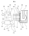
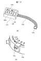
- FIG. 2 is a view including a cross section of the stirring mechanism 109 shown in FIG. 1, and is a cross section parallel to the vertical direction and the radial direction of the reaction disk 108.
- the electrical circuit arranged on the host computer side with respect to the connector 112 is shown in a schematic diagram.
- the automatic chemical analyzer agitates the reaction vessel 107 by irradiating the reaction vessel 107 with a sound wave by the stirring mechanism 109.
- the automated chemical analyzer comprises the following components: -Piezoelectric element 201 that generates sound waves (for example, ultrasonic waves) -Jig 202 for mounting the piezoelectric element 201 on the constant temperature bath 111 -Divided electrodes 211 (plural electrodes) provided on the surface of the piezoelectric element 201 and one or more constant temperature water side electrodes 210 -Power amplifier 203 (driver) that drives the piezoelectric element 201 by applying a voltage to each electrode and generates sound waves.
- the stirring mechanism 109 of FIG. 1 includes the connector 112 of FIG. 2, the piezoelectric element 201, the jig 202, the divided electrodes 211, and the constant temperature water side electrode 210.
- the stirring mechanism 109 is connected to the power amplifier 203 via the connector 112.
- the power amplifier 203 also operates according to a command from the host computer.
- the automatic chemical analyzer includes an impedance measuring circuit 204 for measuring the electrical impedance spectrum of the piezoelectric element 201 (hereinafter, may be abbreviated as "ImpS").
- the ImpS of the piezoelectric element 201 is represented by, for example, a set of ImpS related to each divided electrode 211 (that is, ImpS between each divided electrode 211 and the constant temperature water side electrode 210).
- the piezoelectric element 201 is arranged so that one surface (air side surface) is in contact with air and the other surface (constant temperature water side surface) is in contact with constant temperature water 209.
- the split electrode 211 is arranged on the side surface of the air, and the constant temperature water side electrode 210 is arranged on the side surface of the constant temperature water. A part of the constant temperature water side electrode 210 is folded back to the air side along the lower end surface of the piezoelectric element 201 as shown in FIG.
- the dividing electrode 211 is divided into upper and lower parts as shown by a broken line frame in FIG.
- 14 split electrodes 211 are provided (only a part thereof is shown in FIG. 2 and the like).
- the dividing electrodes 211 are provided at different height positions.
- the dimensions and shape of each split electrode 211 can be arbitrarily designed individually, but in this embodiment, the first to thirteenth split electrodes 211 from the top all have the same shape, and the 14th (bottom) split electrode 211 has the same shape. Only the split electrode 211 is formed slightly longer than the other split electrodes 211.
- Each split electrode 211 is connected to each pin of the connector 112 on a one-to-one basis.
- the power amplifier 203 includes a function generation circuit 205 that generates a drive waveform, a final stage amplifier circuit 206 that amplifies the waveform to a desired power, and a current monitor 207 that measures the current flowing through the piezoelectric element when a voltage is applied.
- the current monitor 207 may be configured to utilize, for example, an electromagnetic coupling, and a configuration example is disclosed in Patent Document 4.
- a relay group 208 is arranged between the power amplifier 203 and the connector 112.
- the relay group 208 includes a plurality of switches, and the opening and closing of each switch is controlled by a command from the host computer. That is, the relay group 208 functions as a switch device for switching the connection between the power amplifier 203 and each of the divided electrodes 211.
- the host computer detects the liquid level position (liquid level) of the agitated liquid in the reaction vessel 107 (an example of the detection method will be described later). Then, one or more split electrodes 211 at appropriate positions are selected according to the liquid level position. Then, the relay group 208 is controlled so as to apply a voltage to the selected split electrode 211. As a result, the position of irradiating the reaction vessel 107 with ultrasonic waves is adjusted.
- changeover switches 212 and 213 for switching whether the piezoelectric element 201 and the power amplifier 203 are connected or the piezoelectric element 201 and the impedance measurement circuit 204 are connected are provided. is set up. During the stirring operation, the changeover switch 212 is connected to the terminal 214 of the power amplifier 203, and the changeover switch 213 is connected to the terminal 215 (connected to the ground 216). On the other hand, at the time of ImpS measurement, the changeover switch 212 is connected to the output terminal 217 of the impedance measurement circuit 204, and the changeover switch 213 is connected to the input terminal 218 of the impedance measurement circuit 204.
- the power amplifier 203 is provided with an information communication means 219, and the host computer controls the power amplifier 203 via the information communication means 219.
- the impedance measuring circuit 204 is provided with the information communication means 220, and the host computer controls the impedance measuring circuit 204 via the information communication means 220. Further, the impedance measurement circuit 204 transmits the ImpS measurement result to the host computer via the information communication means 220.
- the impedance measurement circuit 204 and the host computer function as an electronic circuit for measuring ImpS of the piezoelectric element 201 by applying a voltage to each of the divided electrodes 211.
- the impedance measurement circuit 204 does not have to be a component independent of the host computer as shown in FIG. 2, and a single electronic circuit in which the impedance measurement circuit 204 and the host computer are integrated may be provided. Further, in the following, the operation of the host computer and the impedance measurement circuit 204 can be realized as the operation of a single electronic circuit.
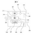
- FIG. 3 is a configuration example of the impedance measurement circuit 204 described with reference to FIG.
- a direct digital synthesizer (hereinafter referred to as DDS) 301 generates a sinusoidal waveform voltage of an arbitrary frequency. It is output from the output terminal 303 via an amplifier 302 that amplifies the voltage of the waveform.
- DDS direct digital synthesizer
- the output terminal 303 is connected to the split electrode 211 via the relay group 208, and a sinusoidal waveform voltage is applied to the piezoelectric element 201 via the split electrode 211.
- the relay group 208 functions as a switch device for switching the connection between the host computer and the impedance measurement circuit 204 and each of the divided electrodes 211.
- the magnitude of the voltage applied here can be appropriately designed by those skilled in the art according to the characteristics of the piezoelectric element 201 and the like, but for example, a voltage smaller than the voltage applied during the stirring operation (for example, a voltage called a weak voltage). ), It is possible to prevent the piezoelectric element 201 from being damaged.
- the current flowing through the piezoelectric element 201 when a voltage is applied flows into the input terminal 304 via the constant temperature water side electrode 210 and the relay group 208, and is detected as a voltage value by the detection resistor 305.
- the voltage signal due to the current is further amplified by the log amplifier 307 (LogAmp) via the operational amplifier 306 which is linearly amplified with an appropriate gain.
- the voltage applied to the piezoelectric element 201 from the output terminal 303 is input to the micro control unit (Micro Control Unit, abbreviated as MCU) 310 via the wiring 308. Further, the voltage value due to the current output from the logarithmic amplifier 307 is input to the MCU 310 via the wiring 309.
- MCU Micro Control Unit
- the voltage input to the MCU 310 is A / D converted.
- the MCU 310 sends a control signal 311 to the DDS 301 to sweep the frequency of the generated sine wave in a desired frequency range.
- the frequency at this time, the voltage applied from the output terminal 303, and the measured voltage corresponding to the current flowing through the piezoelectric element 201 are stored in the memory in the MCU 310, and ImpS is stored in the host computer via the information communication means 220. It is sent as a measurement result.
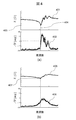
- FIG. 4 is an example of the result of measuring ImpS of a normal piezoelectric element.
- FIG. 4A shows the result when the piezoelectric element is measured in air
- FIG. 4B shows the result when one side of the same piezoelectric element is in contact with constant temperature water.
- of the electric impedance and the phase difference ⁇ Z of the applied voltage and the current value are plotted with the drive frequency on the horizontal axis.
- the ImpS of the piezoelectric element was measured using 13 split electrodes having a uniform shape (same width and length).
- and the profile group 402 having the phase difference ⁇ Z are displayed.
- a uniform profile is measured.
- the frequency at which the absolute value becomes the minimum value 403 is the resonance frequency 404 of this piezoelectric element.
- the phase difference at the resonance frequency 404 is almost zero, indicating the state of the point where the piezoelectric element changes from capacitive to inductive.
- this resonance frequency may vary by several percent for each piezoelectric element, but in the experiment of FIG. 4, the problem of individual difference of the piezoelectric element is solved by utilizing the invention published in Patent Document 5. is doing.
- and the profile group 406 with the phase difference ⁇ Z are displayed.
- the specific acoustic impedance of water with respect to air is 3000 times or more, and since the acoustic impedance is high, the acoustic load is high, so that the electrical impedance rises by that amount.
- this characteristic is used to detect the liquid level position of the constant temperature water and the liquid level position of the agitated liquid in the reaction vessel.
- FIG. 5 is an example of the result of measuring ImpS of an abnormal piezoelectric element. This example is the case where the piezoelectricity is lost in a part of the piezoelectric element. Similar to FIG. 4B, the results when one side of the piezoelectric element is in contact with constant temperature water are shown.
- the profile obtained from the split electrode corresponding to the portion where the piezoelectricity has disappeared is different from the profile obtained from the split electrode corresponding to the normal portion, and as a result, the profile group varies.
- the profile group 502 has a large variation in the phase difference ⁇ Z as compared with the normal profile group 406 of FIG. 4 (b).
- no sharp resonance characteristic was obtained as compared with the normal profile group 405 in FIG. 4 (b), and the frequency 503 was considered to be the resonance frequency at the normal time.
- the impedance value 504 is greater than the corresponding value 407 in FIG. 4 (b). That is, it is shown that the current is less likely to flow, and the irradiation intensity of the ultrasonic wave is reduced as compared with the normal state.
- the host computer and the impedance measurement circuit 204 measure the ImpS of the piezoelectric element, which is the sound source of the stirring technique, according to the configurations described with reference to FIGS. 1 and 2, and the piezoelectric element is normal based on the profile. Diagnose the presence or absence.
- Specific diagnostic methods and criteria can be appropriately designed by those skilled in the art, but an example of a standard diagnostic method will be described below.
- the results of ImpS measurement obtained from each electrode of a normal piezoelectric element are collected from a large number of normal piezoelectric element specimens and statistically obtained. Create a good population. From the population, a profile consisting of the absolute value of the electrical impedance and the average value of the phase difference at each frequency is created. Then, the normal range based on the standard deviation ⁇ is defined with the average value as the center. For example, the normal range is within ⁇ 2 ⁇ of the average value.
- ImpS is measured for the piezoelectric element to be determined, and it is determined whether or not the ImpS falls within the normal range.
- the piezoelectric element is determined to be normal, and if not (that is, for any of the divided electrodes). , If the electrical impedance is too low or too high at any frequency), the piezoelectric element is determined to be abnormal. In this way, it is determined whether or not the piezoelectric element is normal based on the ImpS related to each divided electrode.
- the above-mentioned diagnostic method is a diagnostic method based on the concept of statistical testing, but a method using machine learning is also available.
- the measurement result obtained by repeating ImpS measurement from a large number of normal piezoelectric element specimens is used as learning data, and the "impS profile of normal piezoelectric element" is used as a learning model (for example, an automatic chemical analyzer).
- a trained model is generated by letting the host computer (host computer) perform machine learning. With this trained model, it is also possible to determine whether or not the ImpS profile of the piezoelectric element to be determined deviates from the "impS profile of a normal piezoelectric element".
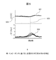
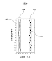
- FIG. 6 is an example of the result of ImpS measurement obtained from a normal piezoelectric element.
- the vertical axis represents the ID number of the divided electrode of the piezoelectric element (1, 2, ..., 13 in order from the top divided electrode).
- the horizontal axis, the absolute value of electrical impedance at resonance of the divided electrodes represents a (
- the profile group 405 (FIG. 4 (b)) of absolute value
- the normalized value is normalized
- is indicated by a black circle. In the case of this normal piezoelectric element, the range of normalization
- measured in air for the same piezoelectric element are shown by white circles in the graph of FIG.
- the reference values used for normalization are the same as for plot 601.
- air range 604 between the divided electrodes was 0.16 to 0.32.
- the plot 602 (measurement in air) is in a lower range than the plot 601 (measurement in a state where one side is in contact with constant temperature water). This is due to the influence of the acoustic load.
- FIG. 7A shows a state in which the liquid level position of the constant temperature water 209 is an appropriate position 701 (for example, a position corresponding to the maximum amount of liquid that can be agitated by the stirring mechanism 109), and there is no liquid to be agitated inside the reaction vessel 107.
- An example of is shown. Since the frequency of the ultrasonic wave used in this embodiment is about several MHz, the ultrasonic wave irradiated from the piezoelectric element 201 propagates in the constant temperature water 209 and reaches the outer surface of the wall of the reaction vessel 107 in this state. Further, the ultrasonic waves pass through the wall of the reaction vessel 107 and reach the inner surface 702.
- FIG. 7B is the result of performing ImpS measurement similar to the method described in FIG.
- is lower than the normal range 603.
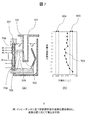
- FIG. 8A shows an example in which the liquid level position of the constant temperature water 209 is the appropriate position 701 and the amount of the agitated liquid 801 is about one third of the appropriate amount.
- FIG. 8B shows the result of measuring
- is large for the split electrodes # 13 and # 12, but begins to fall from the split electrode # 11 and on the split electrodes # 9 and above. It has dropped to the middle range 803 (ie, lower than the normal range 603 and higher than the air range 604).
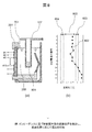
- FIG. 9A shows an example in which the liquid level position of the constant temperature water 209 is the appropriate position 701 and the amount of the agitated liquid 901 is about two-thirds of the appropriate amount.
- FIG. 9B shows the result of measuring
- is large in the divided electrodes # 5 to # 13, but starts to decrease above the divided electrodes # 5, and in the divided electrodes # 1 to # 3. It has dropped to the middle range 803.
- FIG. 10A shows an example in which the liquid level position of the constant temperature water 209 is the appropriate position 701 and the amount of the agitated liquid 1001 exceeds the appropriate amount.
- FIG. 10B shows the result of measuring
- Z r Z r The amount of the agitated liquid can be determined based on
- the amount of the agitated liquid is represented by, for example, the liquid level position of the agitated liquid. In this way, the host computer and the impedance measurement circuit 204 detect the liquid level position of the liquid to be agitated based on the ImpS related to each divided electrode.
- the liquid level position is an appropriate position.
- FIGS. 7 (b), 8 (b) and 9 (b) when the value of normalized
- the reference value or reference range (for example, normal range 603, intermediate range 803, air range 604, etc.) used for determination can be stored by performing ImpS measurement in advance under predetermined conditions.
- the detected liquid level position of the agitated liquid can be applied to various controls.
- the power amplifier 203 may generate sound waves in the piezoelectric element 201 in different ways.
- the "different mode" it is possible to apply a voltage to different divided electrodes depending on the liquid level position.
- the relationship between the liquid level position and the split electrode to which the voltage is applied can be appropriately designed by those skilled in the art. For example, when the liquid level position is low (for example, FIG. 8), a voltage is applied only to the divided electrodes (for example, the divided electrodes # 10 to # 13) at the low position according to the liquid level position, and the liquid level position is higher. In the case (for example, FIG. 9), a voltage can be applied to the divided electrodes at higher positions (for example, the divided electrodes # 4 to # 13).
- the voltage applied to each divided electrode different according to the liquid level position. For example, if the liquid level position is low (for example, FIG. 8), the voltage can be reduced, and if the liquid level position is higher (for example, FIG. 9), the voltage can be increased.
- the ultrasonic wave propagates from the piezoelectric element 201 toward the reaction vessel 107 as a traveling wave 704.
- the ultrasonic waves that reach the reaction vessel 107 are almost totally reflected by the inner surface 702 of the reaction vessel 107, and a reflected wave 705 is generated.
- a standing wave synthesized from the traveling wave 704 and the reflected wave 705 is formed between the inner surface 702 and the surface 706 (vibration surface) of the piezoelectric element 201 on the side in contact with the constant temperature water. Ru.
- the standing wave has a sound pressure distribution in which the antinode (the part where the sound pressure becomes maximum or minimum) and the node (the part where the sound pressure becomes zero) are lined up for each half wavelength of the sound wave in the propagation direction of the sound wave. ..
- the ultrasonic waves radiated from the piezoelectric element 201 are almost totally reflected, so that the sound pressure is always almost zero. That is, since the sound pressure is reflected at this position as a free end, a node is formed on the inner surface 702.
- the reflected wave 705 is the minimum on the surface 706. It is incident in the phase of sound pressure. Further, when the distance is an even multiple, the reflected wave 705 is incident on the surface 706 in the phase of the maximum sound pressure. Since the sound pressure of the reflected wave 705 affects the acoustic load of the piezoelectric element 201, the electric impedance of the piezoelectric element 201 changes accordingly.
- the surface 706 of the piezoelectric element 201 is affected by the reflected wave 705.
- the acoustic load of the piezoelectric element 201 is maximized or minimized. Further, even when the distance is a non-integer multiple, the acoustic load of the piezoelectric element 201 changes between the maximum and the minimum depending on the phase of the reflected wave 705.
- the change in ImpS measured by each of the divided electrodes # 1 to # 13 of the piezoelectric element 201 causes the stirring in the reaction vessel 107 to be agitated.
- the liquid level position that is, the liquid amount can be detected.
- FIG. 11A the agitated liquid in the reaction vessel 107 is filled with a liquid amount that can be mixed or more, but the water level of the constant temperature bath (the liquid level position of the constant temperature water 1101) drops due to some abnormality.
- FIG. 11B shows a plot 1102 of normalization
- is within or higher than the normal range 603 for the split electrodes # 7 to # 13, but declines above the split electrode # 7.
- the range has dropped to 604 in the air.
- the position of the homeothermic water 1101 can be estimated based on the position of the split electrode when the normalized
- the detected constant temperature water level position can be applied to various controls.
- the pros and cons of the stirring operation can be determined according to the liquid level position. That is, the host computer and the impedance measurement circuit 204 determine whether or not the piezoelectric element is in correct contact with the constant temperature water (that is, whether or not the liquid level position of the constant temperature water is sufficiently high) in the ImpS related to each divided electrode. Judgment based on. Then, the power amplifier 203 generates a sound wave in the piezoelectric element when the piezoelectric element is in correct contact with the constant temperature water, and does not generate a sound wave in the piezoelectric element when the piezoelectric element is not in correct contact with the constant temperature water. ..
- the power amplifier 203 can generate a sound wave in the piezoelectric element 201 in a different manner depending on the liquid level position of the constant temperature water (that is, depending on the ImpS related to each divided electrode).
- the "different mode" it is possible to apply a voltage to different divided electrodes depending on the liquid level position.
- the relationship between the liquid level position and the split electrode to which the voltage is applied can be appropriately designed by those skilled in the art. For example, when the liquid level position is low (for example, FIG. 11), a voltage is applied only to the divided electrodes (for example, the divided electrodes # 7 to # 13) at the low position according to the liquid level position, and the liquid level position is higher. In some cases, a voltage can be applied to the split electrodes at higher positions (eg, split electrodes # 4 to # 13).
- FIGS. 7 to 10 and their measurement results are also useful for the chemical automatic analyzer.
- the sample dispensed from the sample dispenser 105 shown in FIG. 1 and the reagent dispensed from the reagent dispenser 106 are weighed and dispensed by a highly accurate controlled syringe pump.
- the conventional automatic chemical analyzer will detect the dispensing error. Without recognizing it, ultrasonic waves are applied to a position that matches the liquid level position of a predetermined amount of liquid.
- FIG. 12 shows an example of the operation procedure of the automatic chemical analyzer according to this embodiment.
- the host computer and the impedance measurement circuit 204 apply a predetermined measurement voltage to each divided electrode to measure ImpS of the piezoelectric element (step S1).
- the power amplifier 203 generates a sound wave (sound wave for stirring) in the piezoelectric element by applying a predetermined stirring voltage to each divided electrode (step S2).
- the measured voltage can be a voltage smaller than the stirring voltage (for example, a weak voltage).
- the "stirring voltage” and “measured voltage” referred to here do not have to be specific voltages, and may be different voltages depending on some conditions. In that case, for example, the maximum value of the measured voltage can be set to a voltage smaller than the minimum value of the stirring voltage.
- the operation of the automatic chemical analyzer according to the measured ImpS is as described above.
- the liquid level position of the liquid to be agitated in the reaction vessel is detected before the start of the agitation operation. If the error in the liquid level position (difference between the liquid level position of the specified liquid level and the actual liquid level position) is within the allowable range from the viewpoint of chemical analysis, the split electrode to be driven is automatically analyzed.
- the host computer of the device can automatically determine or change it to perform ultrasonic irradiation according to the actual liquid level position.
- ImpS measurement of the piezoelectric element according to this embodiment on an automatic chemical analyzer in operation, it is possible not only to detect an abnormality in the piezoelectric element but also to prevent the occurrence of the abnormality.
- the trouble of this automatic chemical analyzer caused by the stirring mechanism 109 can be significantly suppressed.
- the first embodiment of the present invention has been described above.
- the automatic chemical analyzer according to the first embodiment has a function of determining whether or not the piezoelectric element is normal, a function of detecting the liquid level position of the liquid to be stirred, and a function of detecting the liquid level position of constant temperature water. Although it has functions, it is possible to omit some of these functions as a modification.
- these functions are merely examples of functions that utilize the ImpS of the piezoelectric element, and perform other functions based on the ImpS of the piezoelectric element in place of or in addition to these functions. It is also possible to configure. For example, using a precision pipettor or the like, a certain amount of liquid is manually dispensed into the reaction vessel, and the liquid level position of the liquid corresponding to the liquid amount corresponds to any position in the reaction vessel. By measuring whether or not the reaction vessel is used, it can be determined whether or not the piezoelectric element and the reaction vessel have an appropriate relative positional relationship.
- an electronic circuit for measuring the impedance spectrum of FIG. 3 (host computer and impedance measurement circuit 204; Impedance Spectrum Measurement Circuit; hereinafter abbreviated as “ISMC”) is mounted on the automatic chemical analyzer. rice field.
- the second embodiment relates to an ImpS measuring instrument (electrical impedance spectrum measuring instrument) that can be connected to an automatic chemical analyzer (for example, a conventional automatic chemical analyzer) that does not have an ISMC.
- an automatic chemical analyzer for example, a conventional automatic chemical analyzer
- the ImpS measuring instrument according to the second embodiment can be used as a maintenance tool for a conventional automatic chemical analyzer.
- the ISMC (FIG. 3) according to the first embodiment is mainly composed of DDS301, MCU310 and a logarithmic amplifier 307, and all of these parts can now be packaged in an IC of 10 mm or less. Therefore, the circuit portion of the ISMC can be configured on a substrate of, for example, 5 cm ⁇ 9 cm (business card size) or less. The total thickness of the ISMC can be 10 mm or less. By configuring the ImpS measuring instrument in such a small size, the ImpS measuring instrument can be made portable, and the convenience is improved.
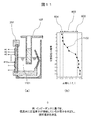
- FIG. 13 shows a configuration example of the ImpS measuring instrument and its connection according to this embodiment.
- FIG. 13A is a configuration example of the ImpS measuring instrument.
- the ImpS measuring instrument includes a host computer, an impedance measuring circuit 204, and a relay group 208.
- the ImpS measuring instrument includes a key operation button 1202 and a display device 1203.
- the key operation button 1202 is an example of an input device for inputting an operation instruction to the host computer and the impedance measurement circuit 204.
- the display device 1203 displays the measured ImpS-based information under the control of the host computer.
- the display device 1203 can display information indicating whether or not the stirring operation may be executed (that is, whether or not the stirring mechanism 109 can appropriately execute the stirring operation).
- information indicating that the stirring operation may be executed is displayed.
- the message "ALL OK !" is displayed as an example of information indicating that the stirring operation may be executed.
- the display device 1203 can display information indicating the liquid level position of the agitated liquid in the reaction vessel. In addition, the display device 1203 can display information indicating the liquid level position of the constant temperature water. The display device 1203 may display information other than these.
- the ImpS measuring instrument is equipped with a cable 1204.
- One end of the cable 1204 is connected to the case 1201 and the other end is connected to the connector 1205.
- the cable 1204 connects the host computer, the impedance measurement circuit 204, and each divided electrode via the connector 1205.
- the conventional automatic chemical analyzer includes a connector 112x and a stirring mechanism 109x.
- the connector 1205 of the ImpS measuring instrument can be connected to the connector 112x of the automatic chemical analyzer.
- the host computer and the impedance measurement circuit 204 can control the divided electrodes of the automatic chemical analyzer via the connector 1205.
- the function described in the first embodiment can be realized in the second embodiment as well.
- a function to determine whether the piezoelectric element is normal a function to detect the liquid level position of the liquid to be agitated, a function to detect the liquid level position of constant temperature water, Etc. can be executed. Therefore, the same effect as in Example 1 can be obtained.
- the ImpS measuring instrument has a portable configuration using the case 1201, and the host computer, the impedance measuring circuit 204, the key operation button 1202, the display device 1203, and the relay group 208 are provided. It is arranged in the portable case 1201.
- the "portable type” means, for example, a size of 5 cm ⁇ 9 cm ⁇ 10 mm or less.
- a larger portable case can also be used.
- a non-portable ImpS measuring instrument for example, a stationary one).
Abstract
La présente invention concerne un appareil d'analyse chimique automatique et un dispositif de spectrométrie d'impédance électrique qui permettent de détecter l'état d'un mécanisme d'agitation avant d'effectuer une opération d'agitation. L'appareil d'analyse chimique automatique distribue un réactif et un échantillon à analyser dans une cuve de réacteur (107) et effectue une agitation en appliquant des ondes sonores à la cuve de réacteur (107). L'appareil d'analyse chimique automatique comprend : un élément piézoélectrique (201) qui génère des ondes sonores ; une pluralité d'électrodes divisées (211) qui sont disposées sur la surface de l'élément piézoélectrique (201) ; un amplificateur de puissance (203) qui amène l'élément piézoélectrique (201) à générer des ondes sonores en appliquant une tension à chacune des électrodes divisées (211) ; un ordinateur hôte et un circuit de mesure d'impédance qui mesurent le spectre d'impédance électrique de chaque électrode divisée (211) en appliquant une tension à chacune des électrodes divisées (211).
Priority Applications (3)
| Application Number | Priority Date | Filing Date | Title |
|---|---|---|---|
| EP21824274.1A EP4170351A1 (fr) | 2020-06-18 | 2021-03-15 | Appareil d'analyse chimique automatique et dispositif de spectrométrie d'impédance électrique |
| US18/008,566 US20230228783A1 (en) | 2020-06-18 | 2021-03-15 | Automatic Chemical Analysis Apparatus and Electrical Impedance Spectrometry Device |
| CN202180039707.1A CN115698726A (zh) | 2020-06-18 | 2021-03-15 | 自动化学分析装置以及电阻抗谱测定器 |
Applications Claiming Priority (2)
| Application Number | Priority Date | Filing Date | Title |
|---|---|---|---|
| JP2020105625A JP7474644B2 (ja) | 2020-06-18 | 2020-06-18 | 自動化学分析装置および電気インピーダンススペクトル測定器 |
| JP2020-105625 | 2020-06-18 |
Publications (1)
| Publication Number | Publication Date |
|---|---|
| WO2021256027A1 true WO2021256027A1 (fr) | 2021-12-23 |
Family
ID=79196309
Family Applications (1)
| Application Number | Title | Priority Date | Filing Date |
|---|---|---|---|
| PCT/JP2021/010389 WO2021256027A1 (fr) | 2020-06-18 | 2021-03-15 | Appareil d'analyse chimique automatique et dispositif de spectrométrie d'impédance électrique |
Country Status (5)
| Country | Link |
|---|---|
| US (1) | US20230228783A1 (fr) |
| EP (1) | EP4170351A1 (fr) |
| JP (1) | JP7474644B2 (fr) |
| CN (1) | CN115698726A (fr) |
| WO (1) | WO2021256027A1 (fr) |
Cited By (4)
| Publication number | Priority date | Publication date | Assignee | Title |
|---|---|---|---|---|
| WO2022244376A1 (fr) * | 2021-05-18 | 2022-11-24 | 株式会社日立ハイテク | Analyseur chimique automatique, kit de maintenance d'analyseur chimique automatique et procédé de maintenance d'analyseur chimique automatique |
| WO2023013344A1 (fr) * | 2021-08-03 | 2023-02-09 | 株式会社日立ハイテク | Dispositif d'analyse chimique |
| WO2023074358A1 (fr) * | 2021-10-27 | 2023-05-04 | 株式会社日立ハイテク | Dispositif d'analyse automatisé et procédé de détermination d'anomalie associé |
| WO2023127355A1 (fr) * | 2021-12-28 | 2023-07-06 | 株式会社日立ハイテク | Appareil et procédé d'analyse chimique |
Families Citing this family (2)
| Publication number | Priority date | Publication date | Assignee | Title |
|---|---|---|---|---|
| WO2023145353A1 (fr) * | 2022-01-31 | 2023-08-03 | 株式会社日立ハイテク | Dispositif d'analyse automatisé |
| CN116381256A (zh) * | 2023-02-28 | 2023-07-04 | 迈克医疗电子有限公司 | 样本分析仪 |
Citations (9)
| Publication number | Priority date | Publication date | Assignee | Title |
|---|---|---|---|---|
| JPS6273165A (ja) * | 1985-09-27 | 1987-04-03 | Hitachi Ltd | 自動分析機の診断装置 |
| JPS641992B2 (fr) | 1980-02-20 | 1989-01-13 | Mitsubishi Electric Corp | |
| JP2003254979A (ja) * | 2002-02-28 | 2003-09-10 | Hitachi High-Technologies Corp | 自動分析装置 |
| JP3661076B2 (ja) | 1998-11-18 | 2005-06-15 | 株式会社日立製作所 | 化学分析装置 |
| JP4112228B2 (ja) | 2000-02-23 | 2008-07-02 | 株式会社日立製作所 | 自動分析装置 |
| JP4406629B2 (ja) | 2006-05-25 | 2010-02-03 | 株式会社日立ハイテクノロジーズ | 化学分析装置 |
| JP2010096638A (ja) * | 2008-10-17 | 2010-04-30 | Hitachi High-Technologies Corp | 自動分析装置 |
| US20160121611A1 (en) * | 2013-07-23 | 2016-05-05 | Oce-Technologies B.V. | Piezo-actuated inkjet print head, method of designing such a print head and a method of manufacturing such a print head |
| JP2020105625A (ja) | 2018-12-26 | 2020-07-09 | Jfeスチール株式会社 | 焼結鉱の製造方法 |
Family Cites Families (1)
| Publication number | Priority date | Publication date | Assignee | Title |
|---|---|---|---|---|
| JP2007040843A (ja) | 2005-08-03 | 2007-02-15 | Hitachi High-Technologies Corp | 自動分析装置 |
-
2020
- 2020-06-18 JP JP2020105625A patent/JP7474644B2/ja active Active
-
2021
- 2021-03-15 WO PCT/JP2021/010389 patent/WO2021256027A1/fr unknown
- 2021-03-15 EP EP21824274.1A patent/EP4170351A1/fr active Pending
- 2021-03-15 CN CN202180039707.1A patent/CN115698726A/zh active Pending
- 2021-03-15 US US18/008,566 patent/US20230228783A1/en active Pending
Patent Citations (10)
| Publication number | Priority date | Publication date | Assignee | Title |
|---|---|---|---|---|
| JPS641992B2 (fr) | 1980-02-20 | 1989-01-13 | Mitsubishi Electric Corp | |
| JPS6273165A (ja) * | 1985-09-27 | 1987-04-03 | Hitachi Ltd | 自動分析機の診断装置 |
| JP3661076B2 (ja) | 1998-11-18 | 2005-06-15 | 株式会社日立製作所 | 化学分析装置 |
| JP4112228B2 (ja) | 2000-02-23 | 2008-07-02 | 株式会社日立製作所 | 自動分析装置 |
| JP2003254979A (ja) * | 2002-02-28 | 2003-09-10 | Hitachi High-Technologies Corp | 自動分析装置 |
| JP3746239B2 (ja) | 2002-02-28 | 2006-02-15 | 株式会社日立ハイテクノロジーズ | 自動分析装置 |
| JP4406629B2 (ja) | 2006-05-25 | 2010-02-03 | 株式会社日立ハイテクノロジーズ | 化学分析装置 |
| JP2010096638A (ja) * | 2008-10-17 | 2010-04-30 | Hitachi High-Technologies Corp | 自動分析装置 |
| US20160121611A1 (en) * | 2013-07-23 | 2016-05-05 | Oce-Technologies B.V. | Piezo-actuated inkjet print head, method of designing such a print head and a method of manufacturing such a print head |
| JP2020105625A (ja) | 2018-12-26 | 2020-07-09 | Jfeスチール株式会社 | 焼結鉱の製造方法 |
Non-Patent Citations (1)
| Title |
|---|
| CHEMICAL ENGINEERING SCIENCE, vol. 60, 2005, pages 5519 - 5528 |
Cited By (4)
| Publication number | Priority date | Publication date | Assignee | Title |
|---|---|---|---|---|
| WO2022244376A1 (fr) * | 2021-05-18 | 2022-11-24 | 株式会社日立ハイテク | Analyseur chimique automatique, kit de maintenance d'analyseur chimique automatique et procédé de maintenance d'analyseur chimique automatique |
| WO2023013344A1 (fr) * | 2021-08-03 | 2023-02-09 | 株式会社日立ハイテク | Dispositif d'analyse chimique |
| WO2023074358A1 (fr) * | 2021-10-27 | 2023-05-04 | 株式会社日立ハイテク | Dispositif d'analyse automatisé et procédé de détermination d'anomalie associé |
| WO2023127355A1 (fr) * | 2021-12-28 | 2023-07-06 | 株式会社日立ハイテク | Appareil et procédé d'analyse chimique |
Also Published As
| Publication number | Publication date |
|---|---|
| EP4170351A1 (fr) | 2023-04-26 |
| US20230228783A1 (en) | 2023-07-20 |
| JP2021196329A (ja) | 2021-12-27 |
| CN115698726A (zh) | 2023-02-03 |
| JP7474644B2 (ja) | 2024-04-25 |
Similar Documents
| Publication | Publication Date | Title |
|---|---|---|
| WO2021256027A1 (fr) | Appareil d'analyse chimique automatique et dispositif de spectrométrie d'impédance électrique | |
| KR100932024B1 (ko) | 마이크로 화학 분석 장치, 마이크로 혼합 장치 및 이를구비하는 마이크로 화학 분석 시스템 | |
| US7808631B2 (en) | Stirrer and analyzer | |
| EP2182369A1 (fr) | Dispositif d'analyse automatique et procede de distribution | |
| WO2022244376A1 (fr) | Analyseur chimique automatique, kit de maintenance d'analyseur chimique automatique et procédé de maintenance d'analyseur chimique automatique | |
| US8252231B2 (en) | Analyzer and its abnormality coping method | |
| CN101501483A (zh) | 电解质分析装置及其测量数据处理方法 | |
| JP2009042049A (ja) | 自動分析装置 | |
| US7802479B2 (en) | Stirring apparatus, abnormality determining method of same, and analyzer | |
| JP2010096638A (ja) | 自動分析装置 | |
| JP2001188070A (ja) | 自動分析装置及び自動分析方法 | |
| JP6224371B2 (ja) | 自動分析装置 | |
| WO2021111795A1 (fr) | Analyseur chimique | |
| WO2023112575A1 (fr) | Dispositif d'analyse automatisé | |
| JP2008268079A (ja) | 液面検知装置及び自動分析装置 | |
| WO2023074358A1 (fr) | Dispositif d'analyse automatisé et procédé de détermination d'anomalie associé | |
| JP5219955B2 (ja) | 分析装置とその撹拌装置駆動方法 | |
| WO2023145353A1 (fr) | Dispositif d'analyse automatisé | |
| JP2008268078A (ja) | 攪拌装置及び自動分析装置 | |
| EP4328591A1 (fr) | Dispositif d'analyse automatique et procédé d'analyse | |
| JP2007232521A (ja) | 攪拌装置と分析装置 | |
| EP3173776B1 (fr) | Système et procédé permettant de mélanger et de tester un liquide | |
| JP2021165693A (ja) | 自動分析装置 | |
| JPWO2020021890A1 (ja) | 血液凝固系解析装置 | |
| JP2007033413A (ja) | 分析装置 |
Legal Events
| Date | Code | Title | Description |
|---|---|---|---|
| 121 | Ep: the epo has been informed by wipo that ep was designated in this application |
Ref document number: 21824274 Country of ref document: EP Kind code of ref document: A1 |
|
| NENP | Non-entry into the national phase |
Ref country code: DE |
|
| ENP | Entry into the national phase |
Ref document number: 2021824274 Country of ref document: EP Effective date: 20230118 |