WO2021256027A1 - Automatic chemical analysis apparatus and electrical impedance spectrometry device - Google Patents
Automatic chemical analysis apparatus and electrical impedance spectrometry device Download PDFInfo
- Publication number
- WO2021256027A1 WO2021256027A1 PCT/JP2021/010389 JP2021010389W WO2021256027A1 WO 2021256027 A1 WO2021256027 A1 WO 2021256027A1 JP 2021010389 W JP2021010389 W JP 2021010389W WO 2021256027 A1 WO2021256027 A1 WO 2021256027A1
- Authority
- WO
- WIPO (PCT)
- Prior art keywords
- piezoelectric element
- electrodes
- automatic chemical
- chemical analyzer
- impedance spectrum
- Prior art date
Links
Images


Classifications
-
- G—PHYSICS
- G01—MEASURING; TESTING
- G01N—INVESTIGATING OR ANALYSING MATERIALS BY DETERMINING THEIR CHEMICAL OR PHYSICAL PROPERTIES
- G01N35/00—Automatic analysis not limited to methods or materials provided for in any single one of groups G01N1/00 - G01N33/00; Handling materials therefor
- G01N35/10—Devices for transferring samples or any liquids to, in, or from, the analysis apparatus, e.g. suction devices, injection devices
- G01N35/1002—Reagent dispensers
-
- G—PHYSICS
- G01—MEASURING; TESTING
- G01N—INVESTIGATING OR ANALYSING MATERIALS BY DETERMINING THEIR CHEMICAL OR PHYSICAL PROPERTIES
- G01N35/00—Automatic analysis not limited to methods or materials provided for in any single one of groups G01N1/00 - G01N33/00; Handling materials therefor
-
- B—PERFORMING OPERATIONS; TRANSPORTING
- B01—PHYSICAL OR CHEMICAL PROCESSES OR APPARATUS IN GENERAL
- B01F—MIXING, e.g. DISSOLVING, EMULSIFYING OR DISPERSING
- B01F31/00—Mixers with shaking, oscillating, or vibrating mechanisms
- B01F31/80—Mixing by means of high-frequency vibrations above one kHz, e.g. ultrasonic vibrations
- B01F31/87—Mixing by means of high-frequency vibrations above one kHz, e.g. ultrasonic vibrations transmitting the vibratory energy by means of a fluid, e.g. by means of air shock waves
-
- B—PERFORMING OPERATIONS; TRANSPORTING
- B01—PHYSICAL OR CHEMICAL PROCESSES OR APPARATUS IN GENERAL
- B01F—MIXING, e.g. DISSOLVING, EMULSIFYING OR DISPERSING
- B01F35/00—Accessories for mixers; Auxiliary operations or auxiliary devices; Parts or details of general application
- B01F35/20—Measuring; Control or regulation
- B01F35/21—Measuring
- B01F35/212—Measuring of the driving system data, e.g. torque, speed or power data
-
- G—PHYSICS
- G01—MEASURING; TESTING
- G01F—MEASURING VOLUME, VOLUME FLOW, MASS FLOW OR LIQUID LEVEL; METERING BY VOLUME
- G01F23/00—Indicating or measuring liquid level or level of fluent solid material, e.g. indicating in terms of volume or indicating by means of an alarm
- G01F23/22—Indicating or measuring liquid level or level of fluent solid material, e.g. indicating in terms of volume or indicating by means of an alarm by measuring physical variables, other than linear dimensions, pressure or weight, dependent on the level to be measured, e.g. by difference of heat transfer of steam or water
- G01F23/28—Indicating or measuring liquid level or level of fluent solid material, e.g. indicating in terms of volume or indicating by means of an alarm by measuring physical variables, other than linear dimensions, pressure or weight, dependent on the level to be measured, e.g. by difference of heat transfer of steam or water by measuring the variations of parameters of electromagnetic or acoustic waves applied directly to the liquid or fluent solid material
- G01F23/296—Acoustic waves
- G01F23/2966—Acoustic waves making use of acoustical resonance or standing waves
-
- G—PHYSICS
- G01—MEASURING; TESTING
- G01N—INVESTIGATING OR ANALYSING MATERIALS BY DETERMINING THEIR CHEMICAL OR PHYSICAL PROPERTIES
- G01N35/00—Automatic analysis not limited to methods or materials provided for in any single one of groups G01N1/00 - G01N33/00; Handling materials therefor
- G01N2035/00465—Separating and mixing arrangements
- G01N2035/00534—Mixing by a special element, e.g. stirrer
- G01N2035/00554—Mixing by a special element, e.g. stirrer using ultrasound
Definitions
- the present invention relates to an automatic chemical analyzer, and more particularly to an apparatus in which reagents and samples in a reaction vessel are agitated by sonic waves.
- the present invention also relates to an electrical impedance spectrum measuring instrument that can be connected to such an automated chemical analyzer.
- Patent Documents 1 to 5 and Non-Patent Document 1 a technique for non-contactly mixing the agitated liquid (sample and reagent) in the reaction vessel by using the effect of the acoustic radiation pressure of intense ultrasonic waves has been developed and automatically. It is mounted on a chemical analyzer and put into practical use.
- a sine wave or a rectangular wave is applied to a piezoelectric element at a frequency close to its thickness resonance frequency to generate ultrasonic waves, and ultrasonic waves are applied from the outside of the reaction vessel toward the liquid to be stirred, thereby being covered. Mix the stirrer.
- main stirring technology ultrasonic non-contact stirring technology
- Japanese Patent No. 3461992 Japanese Patent No. 3661076 Japanese Patent No. 4406629 Japanese Patent No. 3746239 Japanese Patent No. 4112228
- the stirring operation is executed once, and the waveform and value of the current flowing through the piezoelectric element at that time are collated with the predetermined waveform and value set in advance, and the stirring mechanism is used. It is judged whether or not there is an abnormality in. Therefore, the determination is made after the stirring operation.
- the operation of the automatic analyzer may be interrupted.
- Automatic chemical analyzers that analyze hundreds of samples or more per hour are often used for biochemical analysis of blood in the laboratory departments or laboratories of medium-sized or large hospitals, so within a limited time. It is important to be able to analyze the desired number of samples in. Therefore, it is not desirable to interrupt the operation of the automatic analyzer.
- the present invention has been made to solve such a problem, and to provide an automatic chemical analyzer and an electric impedance spectrum measuring instrument capable of detecting the state of a stirring mechanism before performing a stirring operation.
- the purpose is to provide an automatic chemical analyzer and an electric impedance spectrum measuring instrument capable of detecting the state of a stirring mechanism before performing a stirring operation.
- An example of the automatic chemical analyzer according to the present invention is In an automatic chemical analyzer that dispenses a reagent and a sample to be analyzed into a reaction vessel and stirs the reaction vessel by irradiating the reaction vessel with sound waves.
- the automatic chemical analyzer is The piezoelectric element that generates the sound wave and A plurality of electrodes provided on the surface of the piezoelectric element and A driver that generates the sound wave in the piezoelectric element by applying a voltage to each of the electrodes.
- An electronic circuit that measures the electrical impedance spectrum of each of the electrodes by applying a voltage to each of the electrodes. To prepare for.
- An example of the electric impedance spectrum measuring instrument is An electrical impedance spectrum measuring instrument that can be connected to an automatic chemical analyzer.
- the automatic chemical analyzer has a function of dispensing a reagent and a sample to be analyzed into a reaction vessel and stirring the reaction vessel by irradiating the reaction vessel with sound waves.
- the automatic chemical analyzer is The piezoelectric element that generates the sound wave and A plurality of electrodes provided on the surface of the piezoelectric element and A driver that generates the sound wave in the piezoelectric element by applying a voltage to each of the electrodes.
- the electrical impedance spectrum measuring instrument is An electronic circuit that measures the electrical impedance spectrum of each of the electrodes, An input device for inputting an operation instruction to the electronic circuit and A display device that displays information based on the measured electrical impedance spectrum, and A cable connecting the electronic circuit and each of the electrodes, A switch device that switches the connection between the electronic circuit and each of the electrodes, To prepare for.
- This specification includes the disclosure content of Japanese Patent Application No. 2020-105625, which is the basis of the priority of the present application.
- the automatic chemical analyzer and the electric impedance spectrum measuring instrument according to the present invention can detect the state of the stirring mechanism before executing the stirring operation.
- the abnormality is detected as a result of the stirring operation, but also the abnormality is detected in advance, so that stable and continuous operation becomes possible.
- the figure which shows the structural example of the stirring mechanism of FIG. The figure which shows the structural example of the impedance measurement circuit of FIG.
- the electronic components used in this embodiment are appropriate and easy to procure at the time of filing of the present invention, but there is a high possibility that higher-performance electronic components will be distributed in the future, especially for the electronic components that have made remarkable progress. Among them, when it can be substituted as an element used for carrying out the present invention, it may be preferable to use a higher performance component.
- FIG. 1 shows a configuration example of the automatic chemical analyzer according to the first embodiment.
- FIG. 2 shows a configuration example of the stirring mechanism according to the first embodiment.
- -Sample cup 101 containing the sample to be analyzed -Sample disk 102 for installing multiple sample cups 101 -Reagent bottle 103 containing reagents -Reagent cold insulation disk 104 for keeping reagent bottle 103 cold -Sample dispenser 105 for dispensing samples -Reagent dispenser 106 for dispensing reagents -Reaction vessel 107 to which samples and reagents are dispensed -Reaction disk 108 in which the reaction vessel 107 is placed -Agitating mechanism 109 that agitates the liquid to be agitated in the reaction vessel 107 -Absorptiometer 110 that identifies the absorbance characteristics in the reaction vessel 107
- the automatic chemical analyzer dispenses the sample and the reagent into the reaction vessel 107 by the sample dispenser 105 and the reagent dispenser 106, respectively. As a result, a liquid to be agitated is generated in the reaction vessel 107.
- the reaction vessel 107 into which the sample and the reagent are dispensed is arranged along the circumferential direction on the reaction disk 108.
- the reaction vessel 107 rotates clockwise in this embodiment.
- the liquid to be agitated in the reaction vessel 107 is stirred and mixed in a non-contact manner by the stirring mechanism 109.
- the reaction between the mixed sample and the reagent is promoted, and the absorbance characteristic thereof is measured by the absorbance meter 110.
- the reaction vessel 107 is washed by a washing mechanism (not shown). After the washing is completed, the next sample is dispensed into the reaction vessel 107, and the above-mentioned series of analysis sequences is repeated.
- the reaction vessel 107 arranged in the circumferential direction in the reaction disk 108 is in contact with the constant temperature water circulating in the constant temperature bath 111, and is kept at a constant temperature through the constant temperature water having a specified temperature.
- constant temperature water is used as an example of a liquid that mediates a sound wave, but in other examples, the liquid that mediates a sound wave is not limited to a constant temperature liquid, and is not limited to water.
- the automatic chemical analyzer is equipped with a host computer (not shown).
- the host computer exchanges signals with the sample disk 102, the reagent cold insulation disk 104, the sample dispenser 105, the reagent dispenser 106, the reaction disk 108, and the like, and controls each operation sequence by transmitting a command to these.
- the host computer controls the operation of the entire automatic chemical analyzer.
- the host computer can be configured as a known computer.
- a host computer includes an arithmetic means for performing an operation and a storage means for storing information.
- the arithmetic means is, for example, a processor
- the storage means is, for example, a semiconductor memory and a magnetic disk device.
- the host computer may be provided with input means for inputting information, output means for outputting information, communication means for transmitting and receiving information via a communication path, and the like.
- Input means are, for example, keyboards and mice
- output means are, for example, display devices and printing devices
- communication means are, for example, network interfaces.
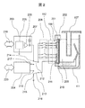
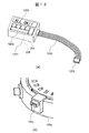
- FIG. 2 is a view including a cross section of the stirring mechanism 109 shown in FIG. 1, and is a cross section parallel to the vertical direction and the radial direction of the reaction disk 108.
- the electrical circuit arranged on the host computer side with respect to the connector 112 is shown in a schematic diagram.
- the automatic chemical analyzer agitates the reaction vessel 107 by irradiating the reaction vessel 107 with a sound wave by the stirring mechanism 109.
- the automated chemical analyzer comprises the following components: -Piezoelectric element 201 that generates sound waves (for example, ultrasonic waves) -Jig 202 for mounting the piezoelectric element 201 on the constant temperature bath 111 -Divided electrodes 211 (plural electrodes) provided on the surface of the piezoelectric element 201 and one or more constant temperature water side electrodes 210 -Power amplifier 203 (driver) that drives the piezoelectric element 201 by applying a voltage to each electrode and generates sound waves.
- the stirring mechanism 109 of FIG. 1 includes the connector 112 of FIG. 2, the piezoelectric element 201, the jig 202, the divided electrodes 211, and the constant temperature water side electrode 210.
- the stirring mechanism 109 is connected to the power amplifier 203 via the connector 112.
- the power amplifier 203 also operates according to a command from the host computer.
- the automatic chemical analyzer includes an impedance measuring circuit 204 for measuring the electrical impedance spectrum of the piezoelectric element 201 (hereinafter, may be abbreviated as "ImpS").
- the ImpS of the piezoelectric element 201 is represented by, for example, a set of ImpS related to each divided electrode 211 (that is, ImpS between each divided electrode 211 and the constant temperature water side electrode 210).
- the piezoelectric element 201 is arranged so that one surface (air side surface) is in contact with air and the other surface (constant temperature water side surface) is in contact with constant temperature water 209.
- the split electrode 211 is arranged on the side surface of the air, and the constant temperature water side electrode 210 is arranged on the side surface of the constant temperature water. A part of the constant temperature water side electrode 210 is folded back to the air side along the lower end surface of the piezoelectric element 201 as shown in FIG.
- the dividing electrode 211 is divided into upper and lower parts as shown by a broken line frame in FIG.
- 14 split electrodes 211 are provided (only a part thereof is shown in FIG. 2 and the like).
- the dividing electrodes 211 are provided at different height positions.
- the dimensions and shape of each split electrode 211 can be arbitrarily designed individually, but in this embodiment, the first to thirteenth split electrodes 211 from the top all have the same shape, and the 14th (bottom) split electrode 211 has the same shape. Only the split electrode 211 is formed slightly longer than the other split electrodes 211.
- Each split electrode 211 is connected to each pin of the connector 112 on a one-to-one basis.
- the power amplifier 203 includes a function generation circuit 205 that generates a drive waveform, a final stage amplifier circuit 206 that amplifies the waveform to a desired power, and a current monitor 207 that measures the current flowing through the piezoelectric element when a voltage is applied.
- the current monitor 207 may be configured to utilize, for example, an electromagnetic coupling, and a configuration example is disclosed in Patent Document 4.
- a relay group 208 is arranged between the power amplifier 203 and the connector 112.
- the relay group 208 includes a plurality of switches, and the opening and closing of each switch is controlled by a command from the host computer. That is, the relay group 208 functions as a switch device for switching the connection between the power amplifier 203 and each of the divided electrodes 211.
- the host computer detects the liquid level position (liquid level) of the agitated liquid in the reaction vessel 107 (an example of the detection method will be described later). Then, one or more split electrodes 211 at appropriate positions are selected according to the liquid level position. Then, the relay group 208 is controlled so as to apply a voltage to the selected split electrode 211. As a result, the position of irradiating the reaction vessel 107 with ultrasonic waves is adjusted.
- changeover switches 212 and 213 for switching whether the piezoelectric element 201 and the power amplifier 203 are connected or the piezoelectric element 201 and the impedance measurement circuit 204 are connected are provided. is set up. During the stirring operation, the changeover switch 212 is connected to the terminal 214 of the power amplifier 203, and the changeover switch 213 is connected to the terminal 215 (connected to the ground 216). On the other hand, at the time of ImpS measurement, the changeover switch 212 is connected to the output terminal 217 of the impedance measurement circuit 204, and the changeover switch 213 is connected to the input terminal 218 of the impedance measurement circuit 204.
- the power amplifier 203 is provided with an information communication means 219, and the host computer controls the power amplifier 203 via the information communication means 219.
- the impedance measuring circuit 204 is provided with the information communication means 220, and the host computer controls the impedance measuring circuit 204 via the information communication means 220. Further, the impedance measurement circuit 204 transmits the ImpS measurement result to the host computer via the information communication means 220.
- the impedance measurement circuit 204 and the host computer function as an electronic circuit for measuring ImpS of the piezoelectric element 201 by applying a voltage to each of the divided electrodes 211.
- the impedance measurement circuit 204 does not have to be a component independent of the host computer as shown in FIG. 2, and a single electronic circuit in which the impedance measurement circuit 204 and the host computer are integrated may be provided. Further, in the following, the operation of the host computer and the impedance measurement circuit 204 can be realized as the operation of a single electronic circuit.
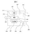
- FIG. 3 is a configuration example of the impedance measurement circuit 204 described with reference to FIG.
- a direct digital synthesizer (hereinafter referred to as DDS) 301 generates a sinusoidal waveform voltage of an arbitrary frequency. It is output from the output terminal 303 via an amplifier 302 that amplifies the voltage of the waveform.
- DDS direct digital synthesizer
- the output terminal 303 is connected to the split electrode 211 via the relay group 208, and a sinusoidal waveform voltage is applied to the piezoelectric element 201 via the split electrode 211.
- the relay group 208 functions as a switch device for switching the connection between the host computer and the impedance measurement circuit 204 and each of the divided electrodes 211.
- the magnitude of the voltage applied here can be appropriately designed by those skilled in the art according to the characteristics of the piezoelectric element 201 and the like, but for example, a voltage smaller than the voltage applied during the stirring operation (for example, a voltage called a weak voltage). ), It is possible to prevent the piezoelectric element 201 from being damaged.
- the current flowing through the piezoelectric element 201 when a voltage is applied flows into the input terminal 304 via the constant temperature water side electrode 210 and the relay group 208, and is detected as a voltage value by the detection resistor 305.
- the voltage signal due to the current is further amplified by the log amplifier 307 (LogAmp) via the operational amplifier 306 which is linearly amplified with an appropriate gain.
- the voltage applied to the piezoelectric element 201 from the output terminal 303 is input to the micro control unit (Micro Control Unit, abbreviated as MCU) 310 via the wiring 308. Further, the voltage value due to the current output from the logarithmic amplifier 307 is input to the MCU 310 via the wiring 309.
- MCU Micro Control Unit
- the voltage input to the MCU 310 is A / D converted.
- the MCU 310 sends a control signal 311 to the DDS 301 to sweep the frequency of the generated sine wave in a desired frequency range.
- the frequency at this time, the voltage applied from the output terminal 303, and the measured voltage corresponding to the current flowing through the piezoelectric element 201 are stored in the memory in the MCU 310, and ImpS is stored in the host computer via the information communication means 220. It is sent as a measurement result.
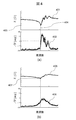
- FIG. 4 is an example of the result of measuring ImpS of a normal piezoelectric element.
- FIG. 4A shows the result when the piezoelectric element is measured in air
- FIG. 4B shows the result when one side of the same piezoelectric element is in contact with constant temperature water.
- of the electric impedance and the phase difference ⁇ Z of the applied voltage and the current value are plotted with the drive frequency on the horizontal axis.
- the ImpS of the piezoelectric element was measured using 13 split electrodes having a uniform shape (same width and length).
- and the profile group 402 having the phase difference ⁇ Z are displayed.
- a uniform profile is measured.
- the frequency at which the absolute value becomes the minimum value 403 is the resonance frequency 404 of this piezoelectric element.
- the phase difference at the resonance frequency 404 is almost zero, indicating the state of the point where the piezoelectric element changes from capacitive to inductive.
- this resonance frequency may vary by several percent for each piezoelectric element, but in the experiment of FIG. 4, the problem of individual difference of the piezoelectric element is solved by utilizing the invention published in Patent Document 5. is doing.
- and the profile group 406 with the phase difference ⁇ Z are displayed.
- the specific acoustic impedance of water with respect to air is 3000 times or more, and since the acoustic impedance is high, the acoustic load is high, so that the electrical impedance rises by that amount.
- this characteristic is used to detect the liquid level position of the constant temperature water and the liquid level position of the agitated liquid in the reaction vessel.
- FIG. 5 is an example of the result of measuring ImpS of an abnormal piezoelectric element. This example is the case where the piezoelectricity is lost in a part of the piezoelectric element. Similar to FIG. 4B, the results when one side of the piezoelectric element is in contact with constant temperature water are shown.
- the profile obtained from the split electrode corresponding to the portion where the piezoelectricity has disappeared is different from the profile obtained from the split electrode corresponding to the normal portion, and as a result, the profile group varies.
- the profile group 502 has a large variation in the phase difference ⁇ Z as compared with the normal profile group 406 of FIG. 4 (b).
- no sharp resonance characteristic was obtained as compared with the normal profile group 405 in FIG. 4 (b), and the frequency 503 was considered to be the resonance frequency at the normal time.
- the impedance value 504 is greater than the corresponding value 407 in FIG. 4 (b). That is, it is shown that the current is less likely to flow, and the irradiation intensity of the ultrasonic wave is reduced as compared with the normal state.
- the host computer and the impedance measurement circuit 204 measure the ImpS of the piezoelectric element, which is the sound source of the stirring technique, according to the configurations described with reference to FIGS. 1 and 2, and the piezoelectric element is normal based on the profile. Diagnose the presence or absence.
- Specific diagnostic methods and criteria can be appropriately designed by those skilled in the art, but an example of a standard diagnostic method will be described below.
- the results of ImpS measurement obtained from each electrode of a normal piezoelectric element are collected from a large number of normal piezoelectric element specimens and statistically obtained. Create a good population. From the population, a profile consisting of the absolute value of the electrical impedance and the average value of the phase difference at each frequency is created. Then, the normal range based on the standard deviation ⁇ is defined with the average value as the center. For example, the normal range is within ⁇ 2 ⁇ of the average value.
- ImpS is measured for the piezoelectric element to be determined, and it is determined whether or not the ImpS falls within the normal range.
- the piezoelectric element is determined to be normal, and if not (that is, for any of the divided electrodes). , If the electrical impedance is too low or too high at any frequency), the piezoelectric element is determined to be abnormal. In this way, it is determined whether or not the piezoelectric element is normal based on the ImpS related to each divided electrode.
- the above-mentioned diagnostic method is a diagnostic method based on the concept of statistical testing, but a method using machine learning is also available.
- the measurement result obtained by repeating ImpS measurement from a large number of normal piezoelectric element specimens is used as learning data, and the "impS profile of normal piezoelectric element" is used as a learning model (for example, an automatic chemical analyzer).
- a trained model is generated by letting the host computer (host computer) perform machine learning. With this trained model, it is also possible to determine whether or not the ImpS profile of the piezoelectric element to be determined deviates from the "impS profile of a normal piezoelectric element".
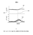
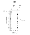
- FIG. 6 is an example of the result of ImpS measurement obtained from a normal piezoelectric element.
- the vertical axis represents the ID number of the divided electrode of the piezoelectric element (1, 2, ..., 13 in order from the top divided electrode).
- the horizontal axis, the absolute value of electrical impedance at resonance of the divided electrodes represents a (
- the profile group 405 (FIG. 4 (b)) of absolute value
- the normalized value is normalized
- is indicated by a black circle. In the case of this normal piezoelectric element, the range of normalization
- measured in air for the same piezoelectric element are shown by white circles in the graph of FIG.
- the reference values used for normalization are the same as for plot 601.
- air range 604 between the divided electrodes was 0.16 to 0.32.
- the plot 602 (measurement in air) is in a lower range than the plot 601 (measurement in a state where one side is in contact with constant temperature water). This is due to the influence of the acoustic load.
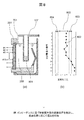
- FIG. 7A shows a state in which the liquid level position of the constant temperature water 209 is an appropriate position 701 (for example, a position corresponding to the maximum amount of liquid that can be agitated by the stirring mechanism 109), and there is no liquid to be agitated inside the reaction vessel 107.
- An example of is shown. Since the frequency of the ultrasonic wave used in this embodiment is about several MHz, the ultrasonic wave irradiated from the piezoelectric element 201 propagates in the constant temperature water 209 and reaches the outer surface of the wall of the reaction vessel 107 in this state. Further, the ultrasonic waves pass through the wall of the reaction vessel 107 and reach the inner surface 702.
- FIG. 7B is the result of performing ImpS measurement similar to the method described in FIG.
- is lower than the normal range 603.
- FIG. 8A shows an example in which the liquid level position of the constant temperature water 209 is the appropriate position 701 and the amount of the agitated liquid 801 is about one third of the appropriate amount.
- FIG. 8B shows the result of measuring
- is large for the split electrodes # 13 and # 12, but begins to fall from the split electrode # 11 and on the split electrodes # 9 and above. It has dropped to the middle range 803 (ie, lower than the normal range 603 and higher than the air range 604).
- FIG. 9A shows an example in which the liquid level position of the constant temperature water 209 is the appropriate position 701 and the amount of the agitated liquid 901 is about two-thirds of the appropriate amount.
- FIG. 9B shows the result of measuring
- is large in the divided electrodes # 5 to # 13, but starts to decrease above the divided electrodes # 5, and in the divided electrodes # 1 to # 3. It has dropped to the middle range 803.
- FIG. 10A shows an example in which the liquid level position of the constant temperature water 209 is the appropriate position 701 and the amount of the agitated liquid 1001 exceeds the appropriate amount.
- FIG. 10B shows the result of measuring
- Z r Z r The amount of the agitated liquid can be determined based on
- the amount of the agitated liquid is represented by, for example, the liquid level position of the agitated liquid. In this way, the host computer and the impedance measurement circuit 204 detect the liquid level position of the liquid to be agitated based on the ImpS related to each divided electrode.
- the liquid level position is an appropriate position.
- FIGS. 7 (b), 8 (b) and 9 (b) when the value of normalized
- the reference value or reference range (for example, normal range 603, intermediate range 803, air range 604, etc.) used for determination can be stored by performing ImpS measurement in advance under predetermined conditions.
- the detected liquid level position of the agitated liquid can be applied to various controls.
- the power amplifier 203 may generate sound waves in the piezoelectric element 201 in different ways.
- the "different mode" it is possible to apply a voltage to different divided electrodes depending on the liquid level position.
- the relationship between the liquid level position and the split electrode to which the voltage is applied can be appropriately designed by those skilled in the art. For example, when the liquid level position is low (for example, FIG. 8), a voltage is applied only to the divided electrodes (for example, the divided electrodes # 10 to # 13) at the low position according to the liquid level position, and the liquid level position is higher. In the case (for example, FIG. 9), a voltage can be applied to the divided electrodes at higher positions (for example, the divided electrodes # 4 to # 13).
- the voltage applied to each divided electrode different according to the liquid level position. For example, if the liquid level position is low (for example, FIG. 8), the voltage can be reduced, and if the liquid level position is higher (for example, FIG. 9), the voltage can be increased.
- the ultrasonic wave propagates from the piezoelectric element 201 toward the reaction vessel 107 as a traveling wave 704.
- the ultrasonic waves that reach the reaction vessel 107 are almost totally reflected by the inner surface 702 of the reaction vessel 107, and a reflected wave 705 is generated.
- a standing wave synthesized from the traveling wave 704 and the reflected wave 705 is formed between the inner surface 702 and the surface 706 (vibration surface) of the piezoelectric element 201 on the side in contact with the constant temperature water. Ru.
- the standing wave has a sound pressure distribution in which the antinode (the part where the sound pressure becomes maximum or minimum) and the node (the part where the sound pressure becomes zero) are lined up for each half wavelength of the sound wave in the propagation direction of the sound wave. ..
- the ultrasonic waves radiated from the piezoelectric element 201 are almost totally reflected, so that the sound pressure is always almost zero. That is, since the sound pressure is reflected at this position as a free end, a node is formed on the inner surface 702.
- the reflected wave 705 is the minimum on the surface 706. It is incident in the phase of sound pressure. Further, when the distance is an even multiple, the reflected wave 705 is incident on the surface 706 in the phase of the maximum sound pressure. Since the sound pressure of the reflected wave 705 affects the acoustic load of the piezoelectric element 201, the electric impedance of the piezoelectric element 201 changes accordingly.
- the surface 706 of the piezoelectric element 201 is affected by the reflected wave 705.
- the acoustic load of the piezoelectric element 201 is maximized or minimized. Further, even when the distance is a non-integer multiple, the acoustic load of the piezoelectric element 201 changes between the maximum and the minimum depending on the phase of the reflected wave 705.
- the change in ImpS measured by each of the divided electrodes # 1 to # 13 of the piezoelectric element 201 causes the stirring in the reaction vessel 107 to be agitated.
- the liquid level position that is, the liquid amount can be detected.
- FIG. 11A the agitated liquid in the reaction vessel 107 is filled with a liquid amount that can be mixed or more, but the water level of the constant temperature bath (the liquid level position of the constant temperature water 1101) drops due to some abnormality.
- FIG. 11B shows a plot 1102 of normalization
- is within or higher than the normal range 603 for the split electrodes # 7 to # 13, but declines above the split electrode # 7.
- the range has dropped to 604 in the air.
- the position of the homeothermic water 1101 can be estimated based on the position of the split electrode when the normalized
- the detected constant temperature water level position can be applied to various controls.
- the pros and cons of the stirring operation can be determined according to the liquid level position. That is, the host computer and the impedance measurement circuit 204 determine whether or not the piezoelectric element is in correct contact with the constant temperature water (that is, whether or not the liquid level position of the constant temperature water is sufficiently high) in the ImpS related to each divided electrode. Judgment based on. Then, the power amplifier 203 generates a sound wave in the piezoelectric element when the piezoelectric element is in correct contact with the constant temperature water, and does not generate a sound wave in the piezoelectric element when the piezoelectric element is not in correct contact with the constant temperature water. ..
- the power amplifier 203 can generate a sound wave in the piezoelectric element 201 in a different manner depending on the liquid level position of the constant temperature water (that is, depending on the ImpS related to each divided electrode).
- the "different mode" it is possible to apply a voltage to different divided electrodes depending on the liquid level position.
- the relationship between the liquid level position and the split electrode to which the voltage is applied can be appropriately designed by those skilled in the art. For example, when the liquid level position is low (for example, FIG. 11), a voltage is applied only to the divided electrodes (for example, the divided electrodes # 7 to # 13) at the low position according to the liquid level position, and the liquid level position is higher. In some cases, a voltage can be applied to the split electrodes at higher positions (eg, split electrodes # 4 to # 13).
- FIGS. 7 to 10 and their measurement results are also useful for the chemical automatic analyzer.
- the sample dispensed from the sample dispenser 105 shown in FIG. 1 and the reagent dispensed from the reagent dispenser 106 are weighed and dispensed by a highly accurate controlled syringe pump.
- the conventional automatic chemical analyzer will detect the dispensing error. Without recognizing it, ultrasonic waves are applied to a position that matches the liquid level position of a predetermined amount of liquid.
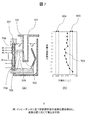
- FIG. 12 shows an example of the operation procedure of the automatic chemical analyzer according to this embodiment.
- the host computer and the impedance measurement circuit 204 apply a predetermined measurement voltage to each divided electrode to measure ImpS of the piezoelectric element (step S1).
- the power amplifier 203 generates a sound wave (sound wave for stirring) in the piezoelectric element by applying a predetermined stirring voltage to each divided electrode (step S2).
- the measured voltage can be a voltage smaller than the stirring voltage (for example, a weak voltage).
- the "stirring voltage” and “measured voltage” referred to here do not have to be specific voltages, and may be different voltages depending on some conditions. In that case, for example, the maximum value of the measured voltage can be set to a voltage smaller than the minimum value of the stirring voltage.
- the operation of the automatic chemical analyzer according to the measured ImpS is as described above.
- the liquid level position of the liquid to be agitated in the reaction vessel is detected before the start of the agitation operation. If the error in the liquid level position (difference between the liquid level position of the specified liquid level and the actual liquid level position) is within the allowable range from the viewpoint of chemical analysis, the split electrode to be driven is automatically analyzed.
- the host computer of the device can automatically determine or change it to perform ultrasonic irradiation according to the actual liquid level position.
- ImpS measurement of the piezoelectric element according to this embodiment on an automatic chemical analyzer in operation, it is possible not only to detect an abnormality in the piezoelectric element but also to prevent the occurrence of the abnormality.
- the trouble of this automatic chemical analyzer caused by the stirring mechanism 109 can be significantly suppressed.
- the first embodiment of the present invention has been described above.
- the automatic chemical analyzer according to the first embodiment has a function of determining whether or not the piezoelectric element is normal, a function of detecting the liquid level position of the liquid to be stirred, and a function of detecting the liquid level position of constant temperature water. Although it has functions, it is possible to omit some of these functions as a modification.
- these functions are merely examples of functions that utilize the ImpS of the piezoelectric element, and perform other functions based on the ImpS of the piezoelectric element in place of or in addition to these functions. It is also possible to configure. For example, using a precision pipettor or the like, a certain amount of liquid is manually dispensed into the reaction vessel, and the liquid level position of the liquid corresponding to the liquid amount corresponds to any position in the reaction vessel. By measuring whether or not the reaction vessel is used, it can be determined whether or not the piezoelectric element and the reaction vessel have an appropriate relative positional relationship.
- an electronic circuit for measuring the impedance spectrum of FIG. 3 (host computer and impedance measurement circuit 204; Impedance Spectrum Measurement Circuit; hereinafter abbreviated as “ISMC”) is mounted on the automatic chemical analyzer. rice field.
- the second embodiment relates to an ImpS measuring instrument (electrical impedance spectrum measuring instrument) that can be connected to an automatic chemical analyzer (for example, a conventional automatic chemical analyzer) that does not have an ISMC.
- an automatic chemical analyzer for example, a conventional automatic chemical analyzer
- the ImpS measuring instrument according to the second embodiment can be used as a maintenance tool for a conventional automatic chemical analyzer.
- the ISMC (FIG. 3) according to the first embodiment is mainly composed of DDS301, MCU310 and a logarithmic amplifier 307, and all of these parts can now be packaged in an IC of 10 mm or less. Therefore, the circuit portion of the ISMC can be configured on a substrate of, for example, 5 cm ⁇ 9 cm (business card size) or less. The total thickness of the ISMC can be 10 mm or less. By configuring the ImpS measuring instrument in such a small size, the ImpS measuring instrument can be made portable, and the convenience is improved.
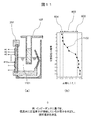
- FIG. 13 shows a configuration example of the ImpS measuring instrument and its connection according to this embodiment.
- FIG. 13A is a configuration example of the ImpS measuring instrument.
- the ImpS measuring instrument includes a host computer, an impedance measuring circuit 204, and a relay group 208.
- the ImpS measuring instrument includes a key operation button 1202 and a display device 1203.
- the key operation button 1202 is an example of an input device for inputting an operation instruction to the host computer and the impedance measurement circuit 204.
- the display device 1203 displays the measured ImpS-based information under the control of the host computer.
- the display device 1203 can display information indicating whether or not the stirring operation may be executed (that is, whether or not the stirring mechanism 109 can appropriately execute the stirring operation).
- information indicating that the stirring operation may be executed is displayed.
- the message "ALL OK !" is displayed as an example of information indicating that the stirring operation may be executed.
- the display device 1203 can display information indicating the liquid level position of the agitated liquid in the reaction vessel. In addition, the display device 1203 can display information indicating the liquid level position of the constant temperature water. The display device 1203 may display information other than these.
- the ImpS measuring instrument is equipped with a cable 1204.
- One end of the cable 1204 is connected to the case 1201 and the other end is connected to the connector 1205.
- the cable 1204 connects the host computer, the impedance measurement circuit 204, and each divided electrode via the connector 1205.
- the conventional automatic chemical analyzer includes a connector 112x and a stirring mechanism 109x.
- the connector 1205 of the ImpS measuring instrument can be connected to the connector 112x of the automatic chemical analyzer.
- the host computer and the impedance measurement circuit 204 can control the divided electrodes of the automatic chemical analyzer via the connector 1205.
- the function described in the first embodiment can be realized in the second embodiment as well.
- a function to determine whether the piezoelectric element is normal a function to detect the liquid level position of the liquid to be agitated, a function to detect the liquid level position of constant temperature water, Etc. can be executed. Therefore, the same effect as in Example 1 can be obtained.
- the ImpS measuring instrument has a portable configuration using the case 1201, and the host computer, the impedance measuring circuit 204, the key operation button 1202, the display device 1203, and the relay group 208 are provided. It is arranged in the portable case 1201.
- the "portable type” means, for example, a size of 5 cm ⁇ 9 cm ⁇ 10 mm or less.
- a larger portable case can also be used.
- a non-portable ImpS measuring instrument for example, a stationary one).
Abstract
The present invention provides an automatic chemical analysis apparatus and an electrical impedance spectrometry device which make it possible to detect the state of a stirring mechanism prior to performing a stirring operation. The automatic chemical analysis apparatus dispenses a reagent and a sample to be analyzed into a reactor vessel 107, and performs stirring by applying sonic waves to the reactor vessel 107. The automatic chemical analysis apparatus comprises: a piezoelectric element 201 that generates sonic waves; a plurality of split electrodes 211 that are provided to the surface of the piezoelectric element 201; a power amplifier 203 that causes the piezoelectric element 201 to generate sonic waves by applying a voltage to each of the split electrodes 211; and a host computer and impedance measuring circuit that that measure the electrical impedance spectrum of each split electrode 211 by applying a voltage to each of the split electrodes 211.
Description
本発明は、自動化学分析装置に係り、特に、反応容器内の試薬およびサンプルを音波によって撹拌するものに関する。また、本発明は、そのような自動化学分析装置と接続可能な電気インピーダンススペクトル測定器に係る。
The present invention relates to an automatic chemical analyzer, and more particularly to an apparatus in which reagents and samples in a reaction vessel are agitated by sonic waves. The present invention also relates to an electrical impedance spectrum measuring instrument that can be connected to such an automated chemical analyzer.
特許文献1~5および非特許文献1によれば、強力超音波の音響放射圧の効果を用いて反応容器内の被撹拌液(サンプルと試薬)を非接触で混合する技術が開発され、自動化学分析装置に実装され実用化されている。
According to Patent Documents 1 to 5 and Non-Patent Document 1, a technique for non-contactly mixing the agitated liquid (sample and reagent) in the reaction vessel by using the effect of the acoustic radiation pressure of intense ultrasonic waves has been developed and automatically. It is mounted on a chemical analyzer and put into practical use.
この技術では、圧電素子にその厚み共振周波数近傍の周波数で正弦波あるいは矩形波などを印加して超音波を発生させ、反応容器外部より被撹拌液に向けて超音波を照射し、これによって被撹拌液を混合する。
In this technology, a sine wave or a rectangular wave is applied to a piezoelectric element at a frequency close to its thickness resonance frequency to generate ultrasonic waves, and ultrasonic waves are applied from the outside of the reaction vessel toward the liquid to be stirred, thereby being covered. Mix the stirrer.
このような超音波非接触撹拌技術(以下、「本撹拌技術」と呼ぶ)を搭載した自動化学分析装置は、ユーザサイトへの導入から数年間以上にわたって使用してもらうことを想定している。従って、自動分析装置を構成する他の機構(分注機構、洗浄機構など)と同様に、自動分析装置の稼働中には各撹拌動作が適正に行われているかをチェックする機能が求められる。
It is assumed that the automatic chemical analyzer equipped with such ultrasonic non-contact stirring technology (hereinafter referred to as "main stirring technology") will be used for several years or more after being introduced to the user site. Therefore, like other mechanisms (dispensing mechanism, cleaning mechanism, etc.) constituting the automatic analyzer, a function of checking whether each stirring operation is properly performed while the automatic analyzer is in operation is required.
とくに特許文献4によれば、本撹拌技術の動作時には圧電素子に流れる電流が各撹拌動作ごとに常に計測および記録され、規定の電流が流れているかを計測することで適正な撹拌が行われたか否かが判定される。規定の電流が流れていなかった場合には、超音波の発信源である圧電素子から所望の超音波が発生していなかったと判定され、その撹拌動作に対する異常やエラー、アラートが自動分析装置によってユーザに提示される。
In particular, according to Patent Document 4, during the operation of this stirring technique, the current flowing through the piezoelectric element is constantly measured and recorded for each stirring operation, and whether proper stirring is performed by measuring whether a specified current is flowing. Whether or not it is determined. If the specified current does not flow, it is determined that the desired ultrasonic wave has not been generated from the piezoelectric element that is the source of the ultrasonic wave, and an abnormality, error, or alert to the stirring operation is detected by the user by the automatic analyzer. Presented at.
しかしながら、従来の技術では、撹拌動作を実行する前に撹拌機構の状態を検知するのが困難であるという課題があった。
However, with the conventional technique, there is a problem that it is difficult to detect the state of the stirring mechanism before executing the stirring operation.
たとえば上述した特許文献4に記載されている技術では、撹拌動作を一度実行し、その時に圧電素子に流れた電流の波形および値を、予め設定した規定の波形および値と照合して、撹拌機構の異常の有無を判定している。従って、撹拌動作後にその判定がされることになる。
For example, in the technique described in Patent Document 4 described above, the stirring operation is executed once, and the waveform and value of the current flowing through the piezoelectric element at that time are collated with the predetermined waveform and value set in advance, and the stirring mechanism is used. It is judged whether or not there is an abnormality in. Therefore, the determination is made after the stirring operation.
撹拌動作の前に撹拌機構の異常が検知できなければ、その撹拌動作で使用した試薬やサンプルが無駄になる可能性がある。
If an abnormality in the stirring mechanism cannot be detected before the stirring operation, the reagents and samples used in the stirring operation may be wasted.
また、撹拌動作の結果として撹拌機構の異常が検知された場合には、自動分析装置の稼働が中断される可能性がある。1時間あたり数百サンプル以上の分析を行う自動化学分析装置は、中規模または大規模の病院の検査部門または検査センタにおいて、血液の生化学分析に使われることが多いので、限られた時間内で所望のサンプル数の分析を行えることが重要である。従って、自動分析装置の稼働を中断されることは望ましくない。
Also, if an abnormality in the stirring mechanism is detected as a result of the stirring operation, the operation of the automatic analyzer may be interrupted. Automatic chemical analyzers that analyze hundreds of samples or more per hour are often used for biochemical analysis of blood in the laboratory departments or laboratories of medium-sized or large hospitals, so within a limited time. It is important to be able to analyze the desired number of samples in. Therefore, it is not desirable to interrupt the operation of the automatic analyzer.
本発明はこのような課題を解決するためになされたものであり、撹拌動作を実行する前に撹拌機構の状態を検知することができる自動化学分析装置および電気インピーダンススペクトル測定器を提供することを目的とする。
The present invention has been made to solve such a problem, and to provide an automatic chemical analyzer and an electric impedance spectrum measuring instrument capable of detecting the state of a stirring mechanism before performing a stirring operation. The purpose.
本発明に係る自動化学分析装置の一例は、
試薬と、分析対象であるサンプルとを反応容器内に分注し、前記反応容器へ音波を照射することにより撹拌する、自動化学分析装置において、
前記自動化学分析装置は、
前記音波を発生する圧電素子と、
前記圧電素子の表面に設けられた複数の電極と、
各前記電極に電圧を印加することにより、前記圧電素子に前記音波を発生させるドライバと、
各前記電極に電圧を印加することにより、各前記電極に係る電気インピーダンススペクトルを測定する電子回路と、
を備える。 An example of the automatic chemical analyzer according to the present invention is
In an automatic chemical analyzer that dispenses a reagent and a sample to be analyzed into a reaction vessel and stirs the reaction vessel by irradiating the reaction vessel with sound waves.
The automatic chemical analyzer is
The piezoelectric element that generates the sound wave and
A plurality of electrodes provided on the surface of the piezoelectric element and
A driver that generates the sound wave in the piezoelectric element by applying a voltage to each of the electrodes.
An electronic circuit that measures the electrical impedance spectrum of each of the electrodes by applying a voltage to each of the electrodes.
To prepare for.
本発明に係る電気インピーダンススペクトル測定器の一例は、
自動化学分析装置と接続可能な、電気インピーダンススペクトル測定器であって、
前記自動化学分析装置は、試薬と、分析対象であるサンプルとを反応容器内に分注し、前記反応容器へ音波を照射することにより撹拌する機能を備え、
前記自動化学分析装置は、
前記音波を発生する圧電素子と、
前記圧電素子の表面に設けられた複数の電極と、
各前記電極に電圧を印加することにより、前記圧電素子に前記音波を発生させるドライバと、
を備え、
前記電気インピーダンススペクトル測定器は、
各前記電極に係る電気インピーダンススペクトルを測定する電子回路と、
前記電子回路に対する動作指示を入力するための入力装置と、
測定された前記電気インピーダンススペクトルに基づく情報を表示する表示装置と、
前記電子回路および各前記電極を接続するケーブルと、
前記電子回路および各前記電極の接続を切り替えるスイッチ装置と、
を備える。
本明細書は本願の優先権の基礎となる日本国特許出願番号2020-105625号の開示内容を包含する。 An example of the electric impedance spectrum measuring instrument according to the present invention is
An electrical impedance spectrum measuring instrument that can be connected to an automatic chemical analyzer.
The automatic chemical analyzer has a function of dispensing a reagent and a sample to be analyzed into a reaction vessel and stirring the reaction vessel by irradiating the reaction vessel with sound waves.
The automatic chemical analyzer is
The piezoelectric element that generates the sound wave and
A plurality of electrodes provided on the surface of the piezoelectric element and
A driver that generates the sound wave in the piezoelectric element by applying a voltage to each of the electrodes.
Equipped with
The electrical impedance spectrum measuring instrument is
An electronic circuit that measures the electrical impedance spectrum of each of the electrodes,
An input device for inputting an operation instruction to the electronic circuit and
A display device that displays information based on the measured electrical impedance spectrum, and
A cable connecting the electronic circuit and each of the electrodes,
A switch device that switches the connection between the electronic circuit and each of the electrodes,
To prepare for.
This specification includes the disclosure content of Japanese Patent Application No. 2020-105625, which is the basis of the priority of the present application.
本発明に係る自動化学分析装置および電気インピーダンススペクトル測定器により、撹拌動作を実行する前に撹拌機構の状態を検知することができる。
The automatic chemical analyzer and the electric impedance spectrum measuring instrument according to the present invention can detect the state of the stirring mechanism before executing the stirring operation.
たとえば、撹拌動作の結果として異常を検知するだけではなく、未然に異常を検知することで、安定かつ持続的な稼働が可能となる。
For example, not only the abnormality is detected as a result of the stirring operation, but also the abnormality is detected in advance, so that stable and continuous operation becomes possible.
撹拌動作をする前に撹拌機構の何らかの不具合を検知でき、その撹拌動作を見送る機能が実現できれば、その撹拌動作で使用する試薬やサンプルを無駄にすることが無くなる。また、その不具合の発生頻度の推移や不具合の要因まで推定できれば、未然に自動化学分析装置への対策(再調整や消耗部品の交換など)が可能になる。
If some malfunction of the stirring mechanism can be detected before the stirring operation and the function of forgoing the stirring operation can be realized, the reagents and samples used in the stirring operation will not be wasted. In addition, if the transition of the frequency of occurrence of the defect and the cause of the defect can be estimated, it is possible to take measures (readjustment, replacement of consumable parts, etc.) for the automatic chemical analyzer.
また、自動分析装置の稼働が中断される可能性を低減できるので、中規模または大規模の病院の検査部門または検査センタにおいても、自動化学分析装置の安定的かつ持続的な稼働が可能になる。
In addition, since the possibility of interruption of the operation of the automatic analyzer can be reduced, stable and sustainable operation of the automatic chemical analyzer becomes possible even in the inspection department or the inspection center of a medium-sized or large hospital. ..
本発明の実施例を以下に説明する。本実施例で用いている電子部品は本発明の出願時点で適切で調達が容易なものであるが、特に進歩の著しい電子部品はより高性能なものが今後流通する可能性が高い。そのなかで、本発明の実施に用いる要素として代替できる場合には、より高性能な部品を用いることが好ましい場合がある。
Examples of the present invention will be described below. The electronic components used in this embodiment are appropriate and easy to procure at the time of filing of the present invention, but there is a high possibility that higher-performance electronic components will be distributed in the future, especially for the electronic components that have made remarkable progress. Among them, when it can be substituted as an element used for carrying out the present invention, it may be preferable to use a higher performance component.
図1に、実施例1に係る自動化学分析装置の構成例を示す。図2に、実施例1に係る撹拌機構の構成例を示す。
FIG. 1 shows a configuration example of the automatic chemical analyzer according to the first embodiment. FIG. 2 shows a configuration example of the stirring mechanism according to the first embodiment.
図1に示す、通り本実施例に係る自動化学分析装置には、以下の構成が実装されている。
‐分析対象であるサンプルを収容するサンプルカップ101
‐サンプルカップ101を複数個設置するためのサンプルディスク102
‐試薬を収容する試薬ボトル103
‐試薬ボトル103を保冷するための試薬保冷ディスク104
‐サンプルを分注するためのサンプルディスペンサ105
‐試薬を分注するための試薬ディスペンサ106
‐サンプルと試薬が分注される反応容器107
‐反応容器107が配置される反応ディスク108
‐反応容器107内の被撹拌液を撹拌する撹拌機構109
‐反応容器107内の吸光特性を特定する吸光度計110 As shown in FIG. 1, the following configuration is implemented in the automatic chemical analyzer according to this embodiment.
-Sample cup 101 containing the sample to be analyzed
-Sample disk 102 for installing multiple sample cups 101
-Reagent bottle 103 containing reagents
-Reagentcold insulation disk 104 for keeping reagent bottle 103 cold
-Sample dispenser 105 for dispensing samples
-Reagent dispenser 106 for dispensing reagents
-Reaction vessel 107 to which samples and reagents are dispensed
-Reaction disk 108 in which the reaction vessel 107 is placed
-Agitatingmechanism 109 that agitates the liquid to be agitated in the reaction vessel 107
-Absorptiometer 110 that identifies the absorbance characteristics in the reaction vessel 107
‐分析対象であるサンプルを収容するサンプルカップ101
‐サンプルカップ101を複数個設置するためのサンプルディスク102
‐試薬を収容する試薬ボトル103
‐試薬ボトル103を保冷するための試薬保冷ディスク104
‐サンプルを分注するためのサンプルディスペンサ105
‐試薬を分注するための試薬ディスペンサ106
‐サンプルと試薬が分注される反応容器107
‐反応容器107が配置される反応ディスク108
‐反応容器107内の被撹拌液を撹拌する撹拌機構109
‐反応容器107内の吸光特性を特定する吸光度計110 As shown in FIG. 1, the following configuration is implemented in the automatic chemical analyzer according to this embodiment.
-
-
-
-Reagent
-
-
-
-
-Agitating
-
自動化学分析装置は、サンプルと試薬を、それぞれサンプルディスペンサ105および試薬ディスペンサ106によって、反応容器107に分注する。これによって反応容器107内に被撹拌液が生成される。サンプルと試薬が分注された反応容器107は、反応ディスク108上に、周方向に沿って配置されている。反応容器107は、この実施例では時計回りに回転する。反応容器107内の被撹拌液は、撹拌機構109において非接触で撹拌され混合される。混合されたサンプルと試薬は反応が促進され、その吸光特性が吸光度計110で測定される。吸光度計測(すなわち分析)が終了した後、図示していない洗浄機構によって反応容器107が洗浄される。洗浄終了後の反応容器107には次のサンプルが分注され、上述した一連の分析シーケンスが繰り返される。
The automatic chemical analyzer dispenses the sample and the reagent into the reaction vessel 107 by the sample dispenser 105 and the reagent dispenser 106, respectively. As a result, a liquid to be agitated is generated in the reaction vessel 107. The reaction vessel 107 into which the sample and the reagent are dispensed is arranged along the circumferential direction on the reaction disk 108. The reaction vessel 107 rotates clockwise in this embodiment. The liquid to be agitated in the reaction vessel 107 is stirred and mixed in a non-contact manner by the stirring mechanism 109. The reaction between the mixed sample and the reagent is promoted, and the absorbance characteristic thereof is measured by the absorbance meter 110. After the absorbance measurement (ie, analysis) is completed, the reaction vessel 107 is washed by a washing mechanism (not shown). After the washing is completed, the next sample is dispensed into the reaction vessel 107, and the above-mentioned series of analysis sequences is repeated.
なお、反応ディスク108において周方向に配置された反応容器107は、恒温槽111中を循環する恒温水と接触しており、指定された温度の恒温水を介して一定温度に保たれている。なお、本実施例では音波を媒介する液体の例として恒温水を用いるが、他の実施例では音波を媒介する液体は恒温のものに限られず、また水にも限られない。
The reaction vessel 107 arranged in the circumferential direction in the reaction disk 108 is in contact with the constant temperature water circulating in the constant temperature bath 111, and is kept at a constant temperature through the constant temperature water having a specified temperature. In this embodiment, constant temperature water is used as an example of a liquid that mediates a sound wave, but in other examples, the liquid that mediates a sound wave is not limited to a constant temperature liquid, and is not limited to water.
自動化学分析装置には、図示しないホストコンピュータが搭載されている。ホストコンピュータは、サンプルディスク102、試薬保冷ディスク104、サンプルディスペンサ105、試薬ディスペンサ106、反応ディスク108、等と信号のやり取りを行い、これらに指令を送信することにより、各々の動作シーケンスを制御する。また、ホストコンピュータは、自動化学分析装置全体の動作を制御する。
The automatic chemical analyzer is equipped with a host computer (not shown). The host computer exchanges signals with the sample disk 102, the reagent cold insulation disk 104, the sample dispenser 105, the reagent dispenser 106, the reaction disk 108, and the like, and controls each operation sequence by transmitting a command to these. In addition, the host computer controls the operation of the entire automatic chemical analyzer.
ホストコンピュータは、公知のコンピュータとして構成することができる。たとえば、ホストコンピュータは、演算を行う演算手段と、情報を格納する記憶手段とを備える。演算手段はたとえばプロセッサであり、記憶手段はたとえば半導体メモリおよび磁気ディスク装置である。また、ホストコンピュータは、情報を入力するための入力手段、情報を出力するための出力手段、通信路を介して情報を送受信するための通信手段、等を備えてもよい。入力手段はたとえばキーボードおよびマウスであり、出力手段はたとえばディスプレイ装置および印刷装置であり、通信手段はたとえばネットワークインタフェースである。
The host computer can be configured as a known computer. For example, a host computer includes an arithmetic means for performing an operation and a storage means for storing information. The arithmetic means is, for example, a processor, and the storage means is, for example, a semiconductor memory and a magnetic disk device. Further, the host computer may be provided with input means for inputting information, output means for outputting information, communication means for transmitting and receiving information via a communication path, and the like. Input means are, for example, keyboards and mice, output means are, for example, display devices and printing devices, and communication means are, for example, network interfaces.
図2は、図1で示した撹拌機構109の断面を含む図であり、鉛直方向および反応ディスク108の径方向に平行な断面によるものである。コネクタ112に対してホストコンピュータ側に配置される電気的な回路は、模式的な図で示している。
FIG. 2 is a view including a cross section of the stirring mechanism 109 shown in FIG. 1, and is a cross section parallel to the vertical direction and the radial direction of the reaction disk 108. The electrical circuit arranged on the host computer side with respect to the connector 112 is shown in a schematic diagram.
自動化学分析装置は、撹拌機構109によって反応容器107へ音波を照射することにより撹拌する。このために、自動化学分析装置は、以下の構成要素を備える。
‐音波(たとえば超音波)を発生する圧電素子201
‐圧電素子201を恒温槽111へマウントするための治具202
‐圧電素子201の表面に設けられた分割電極211(複数の電極)および1つ以上の恒温水側電極210
‐各電極に電圧を印加することにより圧電素子201を駆動し、音波を発生させる電力増幅器203(ドライバ) The automatic chemical analyzer agitates thereaction vessel 107 by irradiating the reaction vessel 107 with a sound wave by the stirring mechanism 109. To this end, the automated chemical analyzer comprises the following components:
-Piezoelectric element 201 that generates sound waves (for example, ultrasonic waves)
-Jig 202 for mounting the piezoelectric element 201 on the constant temperature bath 111
-Divided electrodes 211 (plural electrodes) provided on the surface of thepiezoelectric element 201 and one or more constant temperature water side electrodes 210
-Power amplifier 203 (driver) that drives thepiezoelectric element 201 by applying a voltage to each electrode and generates sound waves.
‐音波(たとえば超音波)を発生する圧電素子201
‐圧電素子201を恒温槽111へマウントするための治具202
‐圧電素子201の表面に設けられた分割電極211(複数の電極)および1つ以上の恒温水側電極210
‐各電極に電圧を印加することにより圧電素子201を駆動し、音波を発生させる電力増幅器203(ドライバ) The automatic chemical analyzer agitates the
-
-
-Divided electrodes 211 (plural electrodes) provided on the surface of the
-Power amplifier 203 (driver) that drives the
図1の撹拌機構109は、図2のコネクタ112と、圧電素子201と、治具202と、各分割電極211と、恒温水側電極210とを備える。撹拌機構109は、コネクタ112を介して電力増幅器203に接続されている。電力増幅器203もホストコンピュータからの指令に従って動作する。
The stirring mechanism 109 of FIG. 1 includes the connector 112 of FIG. 2, the piezoelectric element 201, the jig 202, the divided electrodes 211, and the constant temperature water side electrode 210. The stirring mechanism 109 is connected to the power amplifier 203 via the connector 112. The power amplifier 203 also operates according to a command from the host computer.
自動化学分析装置は、圧電素子201の電気インピーダンススペクトル(以下「ImpS」と略記する場合がある)を測定するためのインピーダンス測定回路204を備える。圧電素子201のImpSは、たとえば、各分割電極211に係るImpS(すなわち、各分割電極211と恒温水側電極210との間におけるImpS)の集合によって表される。
The automatic chemical analyzer includes an impedance measuring circuit 204 for measuring the electrical impedance spectrum of the piezoelectric element 201 (hereinafter, may be abbreviated as "ImpS"). The ImpS of the piezoelectric element 201 is represented by, for example, a set of ImpS related to each divided electrode 211 (that is, ImpS between each divided electrode 211 and the constant temperature water side electrode 210).
圧電素子201は、一方の面(空気側面)が空気と接触し、他方の面(恒温水側面)が恒温水209と接触するよう配置される。分割電極211は空気側面に配置され、恒温水側電極210は恒温水側面に配置される。なお、恒温水側電極210の一部は、図2のように圧電素子201の下側の端面にそって空気側面に折り返されている。
The piezoelectric element 201 is arranged so that one surface (air side surface) is in contact with air and the other surface (constant temperature water side surface) is in contact with constant temperature water 209. The split electrode 211 is arranged on the side surface of the air, and the constant temperature water side electrode 210 is arranged on the side surface of the constant temperature water. A part of the constant temperature water side electrode 210 is folded back to the air side along the lower end surface of the piezoelectric element 201 as shown in FIG.
分割電極211は、図2に破線枠で示すように上下に分割されている。本実施例では、14個の分割電極211が設けられる(図2等には一部のみ示す)。分割電極211は、それぞれ異なる高さ位置に設けられる。各分割電極211の寸法および形状は、個別に任意に設計可能であるが、本実施例では、上から1~13番目の分割電極211はすべて同一形状であり、14番目(一番下)の分割電極211だけが他の分割電極211より若干長く形成されている。各分割電極211は、それぞれコネクタ112の各ピンに一対一で接続されている。
The dividing electrode 211 is divided into upper and lower parts as shown by a broken line frame in FIG. In this embodiment, 14 split electrodes 211 are provided (only a part thereof is shown in FIG. 2 and the like). The dividing electrodes 211 are provided at different height positions. The dimensions and shape of each split electrode 211 can be arbitrarily designed individually, but in this embodiment, the first to thirteenth split electrodes 211 from the top all have the same shape, and the 14th (bottom) split electrode 211 has the same shape. Only the split electrode 211 is formed slightly longer than the other split electrodes 211. Each split electrode 211 is connected to each pin of the connector 112 on a one-to-one basis.
電力増幅器203は、駆動波形を発生させる関数発生回路205と、その波形を所望の電力に増幅する終段増幅回路206と、電圧印加時に圧電素子に流れる電流を測定する電流モニタ207とを備える。電流モニタ207は、たとえば電磁的なカップリングを利用する構成とすることができ、構成例は特許文献4で公開されている。
The power amplifier 203 includes a function generation circuit 205 that generates a drive waveform, a final stage amplifier circuit 206 that amplifies the waveform to a desired power, and a current monitor 207 that measures the current flowing through the piezoelectric element when a voltage is applied. The current monitor 207 may be configured to utilize, for example, an electromagnetic coupling, and a configuration example is disclosed in Patent Document 4.
この電力増幅器203とコネクタ112との間には、リレー群208が配置されている。リレー群208は複数のスイッチを備え、ホストコンピュータからの指令で各スイッチの開閉が制御される。すなわち、リレー群208は、電力増幅器203と、各分割電極211との接続を切り替えるスイッチ装置として機能する。
A relay group 208 is arranged between the power amplifier 203 and the connector 112. The relay group 208 includes a plurality of switches, and the opening and closing of each switch is controlled by a command from the host computer. That is, the relay group 208 functions as a switch device for switching the connection between the power amplifier 203 and each of the divided electrodes 211.
たとえば、ホストコンピュータは、反応容器107内の被撹拌液の液面位置(液面レベル)を検出する(検出方法の例は後述する)。そして、液面位置に合わせて、適切な位置の分割電極211を1つ以上選択する。そして、選択した分割電極211に電圧を印加するようリレー群208を制御する。これによって、反応容器107への超音波の照射位置が調整される。
For example, the host computer detects the liquid level position (liquid level) of the agitated liquid in the reaction vessel 107 (an example of the detection method will be described later). Then, one or more split electrodes 211 at appropriate positions are selected according to the liquid level position. Then, the relay group 208 is controlled so as to apply a voltage to the selected split electrode 211. As a result, the position of irradiating the reaction vessel 107 with ultrasonic waves is adjusted.
電力増幅器203とリレー群208との間には、圧電素子201と電力増幅器203を接続するか、または、圧電素子201とインピーダンス測定回路204とを接続するかを切り替えるための切り替えスイッチ212および213が設置されている。撹拌動作時には、切り替えスイッチ212は電力増幅器203の端子214に接続され、切り替えスイッチ213は端子215(グランド216に接続されている)に接続される。一方、ImpS測定時には、切り替えスイッチ212はインピーダンス測定回路204の出力端子217に接続され、切り替えスイッチ213はインピーダンス測定回路204の入力端子218に接続される。
Between the power amplifier 203 and the relay group 208, changeover switches 212 and 213 for switching whether the piezoelectric element 201 and the power amplifier 203 are connected or the piezoelectric element 201 and the impedance measurement circuit 204 are connected are provided. is set up. During the stirring operation, the changeover switch 212 is connected to the terminal 214 of the power amplifier 203, and the changeover switch 213 is connected to the terminal 215 (connected to the ground 216). On the other hand, at the time of ImpS measurement, the changeover switch 212 is connected to the output terminal 217 of the impedance measurement circuit 204, and the changeover switch 213 is connected to the input terminal 218 of the impedance measurement circuit 204.
電力増幅器203には情報通信手段219が設けられており、ホストコンピュータはこの情報通信手段219を介して電力増幅器203を制御する。同様に、インピーダンス測定回路204には情報通信手段220が設けられており、ホストコンピュータはこの情報通信手段220を介してインピーダンス測定回路204を制御する。また、インピーダンス測定回路204は、情報通信手段220を介してImpSの測定結果をホストコンピュータに送信する。
The power amplifier 203 is provided with an information communication means 219, and the host computer controls the power amplifier 203 via the information communication means 219. Similarly, the impedance measuring circuit 204 is provided with the information communication means 220, and the host computer controls the impedance measuring circuit 204 via the information communication means 220. Further, the impedance measurement circuit 204 transmits the ImpS measurement result to the host computer via the information communication means 220.
このような構成によって、インピーダンス測定回路204およびホストコンピュータは、各分割電極211に電圧を印加することにより、圧電素子201のImpSを測定する電子回路として機能する。なお、インピーダンス測定回路204は、図2に示すようにホストコンピュータから独立した構成要素とする必要はなく、インピーダンス測定回路204およびホストコンピュータを統合した単一の電子回路が設けられてもよい。また、以下において、ホストコンピュータおよびインピーダンス測定回路204の動作は、単一の電子回路の動作として実現することが可能である。
With such a configuration, the impedance measurement circuit 204 and the host computer function as an electronic circuit for measuring ImpS of the piezoelectric element 201 by applying a voltage to each of the divided electrodes 211. The impedance measurement circuit 204 does not have to be a component independent of the host computer as shown in FIG. 2, and a single electronic circuit in which the impedance measurement circuit 204 and the host computer are integrated may be provided. Further, in the following, the operation of the host computer and the impedance measurement circuit 204 can be realized as the operation of a single electronic circuit.
図3は図2で説明したインピーダンス測定回路204の構成例である。この回路の内部では、ダイレクト・ディジタル・シンセサイザー(Direct Digital Synthesizer, 以下、DDSと表記する)301によって任意の周波数の正弦波形電圧を発生させる。その波形の電圧を電圧増幅するアンプ302を経て、出力端子303から出力される。
FIG. 3 is a configuration example of the impedance measurement circuit 204 described with reference to FIG. Inside this circuit, a direct digital synthesizer (hereinafter referred to as DDS) 301 generates a sinusoidal waveform voltage of an arbitrary frequency. It is output from the output terminal 303 via an amplifier 302 that amplifies the voltage of the waveform.
たとえば、出力端子303は、リレー群208を介して分割電極211に接続されており、分割電極211を介して、圧電素子201に正弦波形電圧が印加される。リレー群208は、ホストコンピュータおよびインピーダンス測定回路204と、各分割電極211との接続を切り替えるスイッチ装置として機能する。
For example, the output terminal 303 is connected to the split electrode 211 via the relay group 208, and a sinusoidal waveform voltage is applied to the piezoelectric element 201 via the split electrode 211. The relay group 208 functions as a switch device for switching the connection between the host computer and the impedance measurement circuit 204 and each of the divided electrodes 211.
ここで印加される電圧の大きさは、圧電素子201の特性等に応じて当業者が適宜設計可能であるが、たとえば撹拌動作時に印加される電圧に比べて小さい電圧(たとえば微弱電圧と呼ばれる電圧)としておくと圧電素子201の破損を防止することができる。電圧印加時に圧電素子201に流れる電流は、恒温水側電極210およびリレー群208を介して入力端子304に流入し、検出抵抗305で電圧値として検出される。
The magnitude of the voltage applied here can be appropriately designed by those skilled in the art according to the characteristics of the piezoelectric element 201 and the like, but for example, a voltage smaller than the voltage applied during the stirring operation (for example, a voltage called a weak voltage). ), It is possible to prevent the piezoelectric element 201 from being damaged. The current flowing through the piezoelectric element 201 when a voltage is applied flows into the input terminal 304 via the constant temperature water side electrode 210 and the relay group 208, and is detected as a voltage value by the detection resistor 305.
その電流に起因する電圧信号は、適切なゲインでリニアに増幅されるオペアンプ306を介して、対数増幅器307(LogAmp)でさらに増幅される。出力端子303から圧電素子201に印加されている電圧は、配線308を介して、マイクロ・コントロール・ユニット(Micro Control Unit, 略してMCUと表記する)310に入力される。また、対数増幅器307から出力される電流に起因する電圧値は、配線309を介してMCU310に入力される。図3に示した実施例ではMCUに内蔵されているA/D変換器の分解能が8~10ビット程度を想定しているため、対数増幅器307を用いているが、より高分解能なA/D変換器を備えたMCUを採用する場合には対数ではなくリニア増幅器でもよい。
The voltage signal due to the current is further amplified by the log amplifier 307 (LogAmp) via the operational amplifier 306 which is linearly amplified with an appropriate gain. The voltage applied to the piezoelectric element 201 from the output terminal 303 is input to the micro control unit (Micro Control Unit, abbreviated as MCU) 310 via the wiring 308. Further, the voltage value due to the current output from the logarithmic amplifier 307 is input to the MCU 310 via the wiring 309. In the embodiment shown in FIG. 3, since the resolution of the A / D converter built in the MCU is assumed to be about 8 to 10 bits, the logarithmic amplifier 307 is used, but the A / D has a higher resolution. When an MCU equipped with a converter is adopted, a linear amplifier may be used instead of a logarithm.
MCU310に入力された電圧はA/D変換される。MCU310はDDS301に制御信号311を送り、発生させる正弦波の周波数を、所望の周波数範囲で掃引させる。このときの周波数と、出力端子303からの印加電圧と、圧電素子201を流れている電流に対応する測定電圧とは、MCU310内のメモリに格納され、情報通信手段220を介してホストコンピュータにImpS測定結果として送信される。
The voltage input to the MCU 310 is A / D converted. The MCU 310 sends a control signal 311 to the DDS 301 to sweep the frequency of the generated sine wave in a desired frequency range. The frequency at this time, the voltage applied from the output terminal 303, and the measured voltage corresponding to the current flowing through the piezoelectric element 201 are stored in the memory in the MCU 310, and ImpS is stored in the host computer via the information communication means 220. It is sent as a measurement result.
図4は、正常な圧電素子のImpSを測定した結果の例である。図4(a)は圧電素子を空気中で測定した場合の結果を示し、図4(b)は同じ圧電素子の片側を恒温水に接触させた状態で測定した場合の結果を示す。
FIG. 4 is an example of the result of measuring ImpS of a normal piezoelectric element. FIG. 4A shows the result when the piezoelectric element is measured in air, and FIG. 4B shows the result when one side of the same piezoelectric element is in contact with constant temperature water.
図4では、電気インピーダンスの絶対値|Z|と、印加電圧および電流値の位相差ΔZとを、横軸に駆動周波数をとってプロットした。一様な形状(同一の幅および長さ)を有する13個の分割電極を用いて、それぞれ圧電素子のImpSを測定した。
In FIG. 4, the absolute value | Z | of the electric impedance and the phase difference ΔZ of the applied voltage and the current value are plotted with the drive frequency on the horizontal axis. The ImpS of the piezoelectric element was measured using 13 split electrodes having a uniform shape (same width and length).
図4(a)には、測定された絶対値|Z|のプロファイル群401と、位相差ΔZのプロファイル群402とが表示されている。いずれも一様なプロファイルが測定されている。絶対値が最小値403となる周波数がこの圧電素子の共振周波数404である。共振周波数404での位相差はほぼゼロであり、この圧電素子が容量性から誘導性に変化する点の状態を示す。
In FIG. 4A, the profile group 401 having the measured absolute value | Z | and the profile group 402 having the phase difference ΔZ are displayed. In each case, a uniform profile is measured. The frequency at which the absolute value becomes the minimum value 403 is the resonance frequency 404 of this piezoelectric element. The phase difference at the resonance frequency 404 is almost zero, indicating the state of the point where the piezoelectric element changes from capacitive to inductive.
この周波数では、圧電素子は他の周波数で駆動されているときに比べ大きく振動し、圧電素子の厚み方向での共振状態にあると考えられる。なお、圧電素子の量産時にはこの共振周波数が圧電素子ごとに数%ばらつくことがあるが、図4の実験では特許文献5で公開されている発明を利用して圧電素子の個体差の問題を解決している。
At this frequency, the piezoelectric element vibrates more than when it is driven at another frequency, and it is considered that the piezoelectric element is in a resonance state in the thickness direction. At the time of mass production of the piezoelectric element, this resonance frequency may vary by several percent for each piezoelectric element, but in the experiment of FIG. 4, the problem of individual difference of the piezoelectric element is solved by utilizing the invention published in Patent Document 5. is doing.
図4(b)には、測定された絶対値|Z|のプロファイル群405と、位相差ΔZのプロファイル群406とが表示されている。
In FIG. 4B, the profile group 405 with the measured absolute value | Z | and the profile group 406 with the phase difference ΔZ are displayed.
図4(a)に示す空気中でのImpS測定結果と、図4(b)に示す片側が水と接触した状態のImpS測定結果とを比較すると、共振周波数はほぼ変わらないが、共振周波数時のインピーダンス値が後者の状態では値407となり、前者での値403に比べて高くなっている。図4(b)の場合では、恒温水に接触している側の圧電素子の表面の振動が恒温水に伝搬し、超音波が圧電素子の表面より照射されている状態となっている。空気に対する水の比音響インピーダンスは3000倍以上であり、音響インピーダンスが高いため音響的な負荷が高くなるために、その分だけ電気インピーダンスが上昇する。本実施例では、この特性を利用して、後述するように、恒温水の液面位置の検知および反応容器内の被撹拌液の液面位置の検知を行う。
Comparing the ImpS measurement result in air shown in FIG. 4 (a) with the ImpS measurement result in the state where one side is in contact with water shown in FIG. 4 (b), the resonance frequency is almost the same, but at the resonance frequency. In the latter state, the impedance value of is 407, which is higher than the value of 403 in the former. In the case of FIG. 4B, the vibration of the surface of the piezoelectric element on the side in contact with the constant temperature water propagates to the constant temperature water, and the ultrasonic wave is irradiated from the surface of the piezoelectric element. The specific acoustic impedance of water with respect to air is 3000 times or more, and since the acoustic impedance is high, the acoustic load is high, so that the electrical impedance rises by that amount. In this embodiment, as will be described later, this characteristic is used to detect the liquid level position of the constant temperature water and the liquid level position of the agitated liquid in the reaction vessel.
図5は、異常な圧電素子のImpSを測定した結果の例である。この例は、圧電素子の一部の部位において圧電性が消失している場合のものである。図4(b)と同様に、圧電素子の片側を恒温水に接触させた状態で測定した場合の結果を示す。
FIG. 5 is an example of the result of measuring ImpS of an abnormal piezoelectric element. This example is the case where the piezoelectricity is lost in a part of the piezoelectric element. Similar to FIG. 4B, the results when one side of the piezoelectric element is in contact with constant temperature water are shown.
圧電性が消失した部位に対応する分割電極から得られるプロファイルは、正常な部位に対応する分割電極から得られるプロファイルとは異なり、結果としてプロファイル群にばらつきが生じる。とくに図5の例では、位相差ΔZについて、図4(b)の正常なプロファイル群406と比べ、プロファイル群502が大きなばらつきを有する。また、絶対値|Z|のプロファイル群501でも、図4(b)の正常なプロファイル群405と比較するとシャープな共振特性が得られておらず、正常時の共振周波数だったと思われる周波数503におけるインピーダンス値504は、図4(b)における対応する値407より大きい。つまり、電流がより流れにくくなっており、正常時に比べ超音波の照射強度が低減していることを示している。
The profile obtained from the split electrode corresponding to the portion where the piezoelectricity has disappeared is different from the profile obtained from the split electrode corresponding to the normal portion, and as a result, the profile group varies. In particular, in the example of FIG. 5, the profile group 502 has a large variation in the phase difference ΔZ as compared with the normal profile group 406 of FIG. 4 (b). Further, even in the profile group 501 having an absolute value | Z |, no sharp resonance characteristic was obtained as compared with the normal profile group 405 in FIG. 4 (b), and the frequency 503 was considered to be the resonance frequency at the normal time. The impedance value 504 is greater than the corresponding value 407 in FIG. 4 (b). That is, it is shown that the current is less likely to flow, and the irradiation intensity of the ultrasonic wave is reduced as compared with the normal state.
本実施例において、ホストコンピュータおよびインピーダンス測定回路204は、図1および図2で説明した構成によって、本撹拌技術の音源である圧電素子のImpSを測定し、そのプロファイルに基づいて圧電素子が正常であるか否かを診断する。具体的な診断方法および診断基準は、当業者が適宜設計可能であるが、標準的な診断方法の一例を以下に説明する。
In this embodiment, the host computer and the impedance measurement circuit 204 measure the ImpS of the piezoelectric element, which is the sound source of the stirring technique, according to the configurations described with reference to FIGS. 1 and 2, and the piezoelectric element is normal based on the profile. Diagnose the presence or absence. Specific diagnostic methods and criteria can be appropriately designed by those skilled in the art, but an example of a standard diagnostic method will be described below.
予め、正常な圧電素子の各電極から得られるImpS測定の結果(すなわち電気インピーダンスの絶対値および位相差に係る周波数スペクトルのプロファイル)を多数の正常な圧電素子の供試体から収集し、その統計的な母集団を作成する。その母集団より、各周波数における電気インピーダンスの絶対値および位相差の平均値からなるプロファイルを作成する。そして、その平均値を中心として、標準偏差σに基づく正常範囲を定義する。例えば、その正常範囲を平均値±2σ以内とする。
In advance, the results of ImpS measurement obtained from each electrode of a normal piezoelectric element (that is, the profile of the frequency spectrum related to the absolute value of the electric impedance and the phase difference) are collected from a large number of normal piezoelectric element specimens and statistically obtained. Create a good population. From the population, a profile consisting of the absolute value of the electrical impedance and the average value of the phase difference at each frequency is created. Then, the normal range based on the standard deviation σ is defined with the average value as the center. For example, the normal range is within ± 2σ of the average value.
そして、判定対象となる圧電素子についてImpSを測定し、そのImpSが正常範囲に収まるか否かを判定する。判定の一例として、すべての分割電極について、かつすべての周波数について、電気インピーダンスが正常範囲内であれば、その圧電素子は正常であると判定され、そうでない場合(すなわち、いずれかの分割電極について、いずれかの周波数で電気インピーダンスが過小または過大となった場合)には、その圧電素子は異常であると判定される。このようにして、各分割電極に係るImpSに基づいて、圧電素子が正常であるか否かが判定される。
Then, ImpS is measured for the piezoelectric element to be determined, and it is determined whether or not the ImpS falls within the normal range. As an example of the determination, if the electrical impedance is within the normal range for all the divided electrodes and for all frequencies, the piezoelectric element is determined to be normal, and if not (that is, for any of the divided electrodes). , If the electrical impedance is too low or too high at any frequency), the piezoelectric element is determined to be abnormal. In this way, it is determined whether or not the piezoelectric element is normal based on the ImpS related to each divided electrode.
上述した診断方法は統計学の検定の考え方に基づく診断方法であるが、機械学習を用いる方法も利用可能である。たとえば、多数の正常な圧電素子の供試体から何度もImpS測定を繰り返して得られる測定結果を学習データとし、『正常な圧電素子のImpSのプロファイル』を学習用モデル(たとえば自動化学分析装置のホストコンピュータ)に機械学習させることによって学習済みモデルを生成する。この学習済みモデルによって、判定対象となる圧電素子のImpSのプロファイルが、『正常な圧電素子のImpSのプロファイル』から逸脱しているか否かを判定させることも可能である。
The above-mentioned diagnostic method is a diagnostic method based on the concept of statistical testing, but a method using machine learning is also available. For example, the measurement result obtained by repeating ImpS measurement from a large number of normal piezoelectric element specimens is used as learning data, and the "impS profile of normal piezoelectric element" is used as a learning model (for example, an automatic chemical analyzer). A trained model is generated by letting the host computer (host computer) perform machine learning. With this trained model, it is also possible to determine whether or not the ImpS profile of the piezoelectric element to be determined deviates from the "impS profile of a normal piezoelectric element".
以上は、圧電素子が正常であるか否かを診断する方法の例についての説明である。次に、正常であることがわかっている圧電素子のImpS測定結果に基づき、撹拌機構109が適切に撹拌動作を実行できる状態であるか否かを判定する方法の例について説明する。
The above is an explanation of an example of a method for diagnosing whether or not the piezoelectric element is normal. Next, an example of a method for determining whether or not the stirring mechanism 109 can appropriately perform the stirring operation based on the ImpS measurement result of the piezoelectric element known to be normal will be described.
図6は、正常な圧電素子より得られたImpS測定の結果例である。縦軸は、圧電素子の分割電極のID番号(一番上の分割電極から順に1,2,…,13とした)を表す。横軸は、各分割電極の共振時における電気インピーダンスの絶対値(|Zr|と記す)を正規化した値(正規化|Zr|)を表す。正規化に用いた基準の値は、圧電素子の片側を恒温水に接触させた状態で絶対値|Z|のプロファイル群405(図4(b))を測定し、共振時のインピーダンス値407を、すべての分割電極(合計13個)について平均した値である。
FIG. 6 is an example of the result of ImpS measurement obtained from a normal piezoelectric element. The vertical axis represents the ID number of the divided electrode of the piezoelectric element (1, 2, ..., 13 in order from the top divided electrode). The horizontal axis, the absolute value of electrical impedance at resonance of the divided electrodes represents a (| Z r | and referred) normalized values (normalized | | Z r). For the reference value used for normalization, the profile group 405 (FIG. 4 (b)) of absolute value | Z | was measured with one side of the piezoelectric element in contact with constant temperature water, and the impedance value 407 at resonance was calculated. , It is an average value for all the divided electrodes (13 in total).
この平均値で各分割電極の|Zr|を除算することにより、正規化した値が正規化|Zr|である。正規化|Zr|のプロット601を黒丸で示す。この正常な圧電素子の場合、正規化|Zr|の範囲(正常範囲603)は、0.92~1.06であった。
By dividing | Z r | of each divided electrode by this average value, the normalized value is normalized | Z r |. The plot 601 of normalization | Zr | is indicated by a black circle. In the case of this normal piezoelectric element, the range of normalization | Zr | (normal range 603) was 0.92 to 1.06.
また、同一の圧電素子について、空気中で測定した|Zr|を正規化した値のプロット602を、図6のグラフ中、白丸で示す。正規化に用いた基準の値は、プロット601の場合と同一である。プロット602について、各分割電極間での正規化|Zr|のばらつき範囲(空気中範囲604)は0.16~0.32であった。なお、このプロット602(空気中での測定)は、プロット601(片面を恒温水に接触させた状態での測定)より低い範囲になっているが、その理由は、上述した通り、圧電素子に対する音響負荷の影響のためである。
Further, plots 602 of normalized values of | Z r | measured in air for the same piezoelectric element are shown by white circles in the graph of FIG. The reference values used for normalization are the same as for plot 601. For plot 602, the variation range of normalization | Zr | (air range 604) between the divided electrodes was 0.16 to 0.32. The plot 602 (measurement in air) is in a lower range than the plot 601 (measurement in a state where one side is in contact with constant temperature water). This is due to the influence of the acoustic load.
図6に示したこれらのプロットをもとに、恒温水の液面位置および反応容器内の被撹拌液の液面位置を検知する方法の例について、以下に説明する。図7~図11に、恒温水209,1101の液面位置または被撹拌液801,901,1001の液面位置が異なる状態の例を示す。
Based on these plots shown in FIG. 6, an example of a method for detecting the liquid level position of the constant temperature water and the liquid level position of the agitated liquid in the reaction vessel will be described below. 7 to 11 show an example in which the liquid level positions of the constant temperature waters 209 and 1101 or the liquid level positions of the agitated liquids 801, 901 and 1001 are different.
図7(a)は、恒温水209の液面位置が適正位置701(たとえば撹拌機構109が撹拌可能な最大液量に対応する位置)であり、反応容器107の内部に被撹拌液がない状態の例を示している。本実施例で使用する超音波の周波数は数MHz程度なので、この状態では圧電素子201から照射された超音波は恒温水209中を伝搬し、反応容器107の壁の外表面に到達する。さらに、超音波は、反応容器107の壁を透過して内表面702まで到達する。
FIG. 7A shows a state in which the liquid level position of the constant temperature water 209 is an appropriate position 701 (for example, a position corresponding to the maximum amount of liquid that can be agitated by the stirring mechanism 109), and there is no liquid to be agitated inside the reaction vessel 107. An example of is shown. Since the frequency of the ultrasonic wave used in this embodiment is about several MHz, the ultrasonic wave irradiated from the piezoelectric element 201 propagates in the constant temperature water 209 and reaches the outer surface of the wall of the reaction vessel 107 in this state. Further, the ultrasonic waves pass through the wall of the reaction vessel 107 and reach the inner surface 702.
図7(b)は、図6で説明した方法と同様なImpS測定を行った結果である。そのプロット703において、ID番号が#13である分割電極(以下「分割電極#13」と略記する。他の分割電極についても同様)では、正規化|Zr|は正常範囲603内であるか、またはこれより高い。一方で、それ以外の分割電極#1~#12では、いずれも正規化|Zr|が正常範囲603より低くなっている。
FIG. 7B is the result of performing ImpS measurement similar to the method described in FIG. In the plot 703, is the normalized | Z r | within the normal range 603 for the divided electrode having the ID number # 13 (hereinafter abbreviated as “divided electrode # 13”; the same applies to the other divided electrodes)? , Or higher than this. On the other hand, in all of the other divided electrodes # 1 to # 12, the normalized | Z r | is lower than the normal range 603.
図8(a)は、恒温水209の液面位置が適正位置701であり、被撹拌液801の量が適正量の3分の1程度である状態の例を示す。この状態について、図6で説明した方法と同じ要領で|Zr|を測定した結果が図8(b)である。図8(b)のプロット802では、正規化|Zr|の値は、分割電極#13および#12については大きいが、分割電極#11から下がり始め、分割電極#9およびこれより上では、中間範囲803(すなわち、正常範囲603より低く、空気中範囲604より高い範囲)まで低下している。
FIG. 8A shows an example in which the liquid level position of the constant temperature water 209 is the appropriate position 701 and the amount of the agitated liquid 801 is about one third of the appropriate amount. FIG. 8B shows the result of measuring | Zr | in the same manner as in the method described with reference to FIG. 6 in this state. In plot 802 of FIG. 8 (b), the value of normalized | Z r | is large for the split electrodes # 13 and # 12, but begins to fall from the split electrode # 11 and on the split electrodes # 9 and above. It has dropped to the middle range 803 (ie, lower than the normal range 603 and higher than the air range 604).
図9(a)は、恒温水209の液面位置が適正位置701であり、被撹拌液901の量が適正量の3分の2程度である状態の例を示す。この状態について、図6で説明した方法と同じ要領で|Zr|を測定した結果が図9(b)である。図9(b)のプロット902では、正規化|Zr|の値は、分割電極#5~#13では大きいが、分割電極#5より上では低下し始め、分割電極#1~#3では中間範囲803まで低下している。
FIG. 9A shows an example in which the liquid level position of the constant temperature water 209 is the appropriate position 701 and the amount of the agitated liquid 901 is about two-thirds of the appropriate amount. FIG. 9B shows the result of measuring | Zr | in the same manner as in the method described with reference to FIG. 6 in this state. In the plot 902 of FIG. 9B, the value of normalized | Z r | is large in the divided electrodes # 5 to # 13, but starts to decrease above the divided electrodes # 5, and in the divided electrodes # 1 to # 3. It has dropped to the middle range 803.
図10(a)は、恒温水209の液面位置が適正位置701であり、被撹拌液1001の量が適正量を超えている状態の例を示す。この状態について、図6で説明した方法と同じ要領で|Zr|を測定した結果が図10(b)である。図10(b)のプロット1002では、正規化|Zr|の値は、すべての分割電極について正常範囲603を超えている。
FIG. 10A shows an example in which the liquid level position of the constant temperature water 209 is the appropriate position 701 and the amount of the agitated liquid 1001 exceeds the appropriate amount. FIG. 10B shows the result of measuring | Zr | in the same manner as in the method described with reference to FIG. 6 in this state. In plot 1002 of FIG. 10B, the value of normalized | Z r | exceeds the normal range 603 for all split electrodes.
以上、図6~図10を用いて説明したように、反応容器内の被撹拌液の量に応じて各分割電極の正規化|Zr|が異なるので、各分割電極の正規化|Zr|に基づいて被撹拌液の量を判定することができる。被撹拌液の量は、たとえば被撹拌液の液面位置によって表される。このように、ホストコンピュータおよびインピーダンス測定回路204は、各分割電極に係るImpSに基づいて、被撹拌液の液面位置を検出する。
As described above with reference to FIGS. 6 to 10, the normalization of the divided electrodes in accordance with the amount of the liquid to be mixed in the reaction vessel | so different, normalization of the divided electrodes | | Z r Z r The amount of the agitated liquid can be determined based on |. The amount of the agitated liquid is represented by, for example, the liquid level position of the agitated liquid. In this way, the host computer and the impedance measurement circuit 204 detect the liquid level position of the liquid to be agitated based on the ImpS related to each divided electrode.
たとえば、図6(b)に示すように、正規化|Zr|がすべて正常範囲603内である場合には、液面位置は適正位置であると判定することができる。また、図7(b)、図8(b)および図9(b)に示すように、特定の分割電極より上側で正規化|Zr|の値が中間範囲803までに低下する場合には、その分割電極の位置に応じて液面位置を推定することができる。また、図10(b)に示すように、正規化|Zr|がすべて正常範囲603を超えている場合には、液面位置は適正位置よりも高いと判定することができる。
For example, as shown in FIG. 6 (b), when the normalized | Z r | are all within the normal range 603, it can be determined that the liquid level position is an appropriate position. Further, as shown in FIGS. 7 (b), 8 (b) and 9 (b), when the value of normalized | Z r | drops to the intermediate range 803 above the specific split electrode. , The liquid level position can be estimated according to the position of the divided electrode. Further, as shown in FIG. 10B, when all the normalized | Zr | exceed the normal range 603, it can be determined that the liquid level position is higher than the appropriate position.
なお、判定に用いる基準値または基準範囲(たとえば、正常範囲603、中間範囲803、空気中範囲604、等)は、予め所定の条件でImpS測定を行って記憶しておくことができる。
The reference value or reference range (for example, normal range 603, intermediate range 803, air range 604, etc.) used for determination can be stored by performing ImpS measurement in advance under predetermined conditions.
検知された被撹拌液の液面位置は、様々な制御に応用することが可能である。一例として、液面位置に応じて(すなわち各分割電極に係るImpSに応じて)、電力増幅器203は、異なる態様で圧電素子201に音波を発生させることができる。
The detected liquid level position of the agitated liquid can be applied to various controls. As an example, depending on the liquid level position (ie, depending on the ImpS associated with each split electrode), the power amplifier 203 may generate sound waves in the piezoelectric element 201 in different ways.
「異なる態様」の具体例として、液面位置に応じて異なる分割電極に電圧を印加することが可能である。液面位置と、電圧を印加する分割電極との関係は、当業者が適宜設計可能である。たとえば、液面位置が低い場合(たとえば図8)には、液面位置に応じた低い位置の分割電極(たとえば分割電極#10~#13)のみに電圧を印加し、液面位置がより高い場合(たとえば図9)には、より高い位置の分割電極(たとえば分割電極#4~#13)に電圧を印加することができる。
As a specific example of the "different mode", it is possible to apply a voltage to different divided electrodes depending on the liquid level position. The relationship between the liquid level position and the split electrode to which the voltage is applied can be appropriately designed by those skilled in the art. For example, when the liquid level position is low (for example, FIG. 8), a voltage is applied only to the divided electrodes (for example, the divided electrodes # 10 to # 13) at the low position according to the liquid level position, and the liquid level position is higher. In the case (for example, FIG. 9), a voltage can be applied to the divided electrodes at higher positions (for example, the divided electrodes # 4 to # 13).
「異なる態様」の別の具体例として、液面位置に応じて各分割電極に印加する電圧を異ならせることが可能である。たとえば、液面位置が低い場合(たとえば図8)には電圧を小さくし、液面位置がより高い場合(たとえば図9)には電圧をより大きくすることができる。
As another specific example of the "different mode", it is possible to make the voltage applied to each divided electrode different according to the liquid level position. For example, if the liquid level position is low (for example, FIG. 8), the voltage can be reduced, and if the liquid level position is higher (for example, FIG. 9), the voltage can be increased.
参考までに、図6~図10に示すような|Zr|の変化が発生する原因として、考えられる理由のひとつを、以下に説明する。なお、仮に以下の説明が主な理由ではない場合、または、以下の説明が完全には当てはまらない場合であっても、上記のような実験結果および本実施例への応用可能性には影響を与えない。
For reference, one of the possible reasons for the change of | Z r | as shown in FIGS. 6 to 10 will be described below. Even if the following explanation is not the main reason, or even if the following explanation does not completely apply, it will affect the above experimental results and applicability to this example. Do not give.
図7(a)を用いて説明する。超音波は、圧電素子201から反応容器107に向かって進行波704として伝搬する。反応容器107に到達した超音波は、反応容器107の内表面702でほぼ全反射し、反射波705が発生する。これによって、内表面702と、圧電素子201のうち恒温水に接触している側の面706(振動面)との間に、進行波704と反射波705から合成される定在波が形成される。
This will be described with reference to FIG. 7 (a). The ultrasonic wave propagates from the piezoelectric element 201 toward the reaction vessel 107 as a traveling wave 704. The ultrasonic waves that reach the reaction vessel 107 are almost totally reflected by the inner surface 702 of the reaction vessel 107, and a reflected wave 705 is generated. As a result, a standing wave synthesized from the traveling wave 704 and the reflected wave 705 is formed between the inner surface 702 and the surface 706 (vibration surface) of the piezoelectric element 201 on the side in contact with the constant temperature water. Ru.
定在波は、音波の伝搬方向に、音波の半波長毎に、腹(音圧が最大あるいは最小となる部分)と、節(音圧がゼロとなる部分)とが並ぶ音圧分布を有する。反応容器107の内表面702では、圧電素子201から照射された超音波がほぼ全反射するので、常に音圧がほぼ0となる。つまり音圧は自由端としてこの位置で反射されるため、内表面702には節が形成される。
The standing wave has a sound pressure distribution in which the antinode (the part where the sound pressure becomes maximum or minimum) and the node (the part where the sound pressure becomes zero) are lined up for each half wavelength of the sound wave in the propagation direction of the sound wave. .. On the inner surface 702 of the reaction vessel 107, the ultrasonic waves radiated from the piezoelectric element 201 are almost totally reflected, so that the sound pressure is always almost zero. That is, since the sound pressure is reflected at this position as a free end, a node is formed on the inner surface 702.
一方、圧電素子201のうち恒温水に接触している側の面706から、反応容器107の内表面702までの距離が半波長の奇数倍である場合には、反射波705は面706に最小音圧の位相で入射する。また、その距離が偶数倍である場合には、反射波705は面706に最大音圧の位相で入射する。この反射波705の音圧は、圧電素子201の音響負荷に影響するため、それに伴い圧電素子201の電気インピーダンスが変化する。
On the other hand, when the distance from the surface 706 on the side of the piezoelectric element 201 in contact with the constant temperature water to the inner surface 702 of the reaction vessel 107 is an odd multiple of a half wavelength, the reflected wave 705 is the minimum on the surface 706. It is incident in the phase of sound pressure. Further, when the distance is an even multiple, the reflected wave 705 is incident on the surface 706 in the phase of the maximum sound pressure. Since the sound pressure of the reflected wave 705 affects the acoustic load of the piezoelectric element 201, the electric impedance of the piezoelectric element 201 changes accordingly.
このように、圧電素子201の面706と、反応容器107の内表面702との間の距離が、半波長の整数倍である場合には、圧電素子201の面706では、反射波705の影響で圧電素子201の音響負荷が最大あるいは最小となる。また、その距離が非整数倍である場合でも、反射波705の位相に応じて、圧電素子201の音響負荷は最大と最小の間で変化する。
As described above, when the distance between the surface 706 of the piezoelectric element 201 and the inner surface 702 of the reaction vessel 107 is an integral multiple of a half wavelength, the surface 706 of the piezoelectric element 201 is affected by the reflected wave 705. The acoustic load of the piezoelectric element 201 is maximized or minimized. Further, even when the distance is a non-integer multiple, the acoustic load of the piezoelectric element 201 changes between the maximum and the minimum depending on the phase of the reflected wave 705.
以上は、超音波の伝搬媒体である恒温水および反応容器107の壁で音波の吸収が全くない場合についての現象の説明の一例である。実際には、伝搬媒体でのその吸収の影響は皆無ではないが、圧電素子201の面706と反応容器107の内表面702との間には定在波に近い音圧分布が形成され、駆動中の圧電素子201のインピーダンスに影響を及ぼす。
The above is an example of the explanation of the phenomenon when there is no absorption of sound waves in the constant temperature water which is the propagation medium of ultrasonic waves and the wall of the reaction vessel 107. Actually, the influence of the absorption by the propagation medium is not completely eliminated, but a sound pressure distribution close to a standing wave is formed between the surface 706 of the piezoelectric element 201 and the inner surface 702 of the reaction vessel 107 to drive the piezoelectric element 201. It affects the impedance of the piezoelectric element 201 inside.
この現象を利用することで、恒温水の液面が適正位置701にある場合に、圧電素子201の各分割電極#1~#13で測定されるImpSの変化から、反応容器107内の被撹拌液の液面位置、すなわち液量を検知することができる。
By utilizing this phenomenon, when the liquid level of the constant temperature water is at the appropriate position 701, the change in ImpS measured by each of the divided electrodes # 1 to # 13 of the piezoelectric element 201 causes the stirring in the reaction vessel 107 to be agitated. The liquid level position, that is, the liquid amount can be detected.
次に、図11を用いて、恒温水の液面位置を検知する方法について説明する。図11(a)は、反応容器107内の被撹拌液は混合可能な液量以上に満たされているが、恒温槽の水位レベル(恒温水1101の液面位置)が何らかの異常で低下している状態の例を示している。図11(b)に、この場合の正規化|Zr|のプロット1102を示す。
Next, a method of detecting the liquid level position of the constant temperature water will be described with reference to FIG. In FIG. 11A, the agitated liquid in the reaction vessel 107 is filled with a liquid amount that can be mixed or more, but the water level of the constant temperature bath (the liquid level position of the constant temperature water 1101) drops due to some abnormality. An example of the state of being present is shown. FIG. 11B shows a plot 1102 of normalization | Zr | in this case.
図11(b)のプロット1102では、正規化|Zr|の値は、分割電極#7~#13では正常範囲603内であるか、またはこれより高いが、分割電極#7より上では低下し始め、分割電極#1~#3では空気中範囲604まで低下している。いずれかの分割電極について、正規化|Zr|が空気中範囲604に属する場合に、恒温水1101の位置をその分割電極の位置に基づいて推定することができる。このように、恒温水1101の液面位置も、|Zr|に基づいて検知することができる。
In plot 1102 of FIG. 11B, the value of normalized | Z r | is within or higher than the normal range 603 for the split electrodes # 7 to # 13, but declines above the split electrode # 7. In the divided electrodes # 1 to # 3, the range has dropped to 604 in the air. For any of the split electrodes, the position of the homeothermic water 1101 can be estimated based on the position of the split electrode when the normalized | Zr | belongs to the air range 604. In this way, the liquid level position of the constant temperature water 1101 can also be detected based on | Z r |.
検知された恒温水の液面位置は、様々な制御に応用することが可能である。一例として、液面位置に応じて、撹拌動作の是非を決定することができる。すなわち、ホストコンピュータおよびインピーダンス測定回路204は、恒温水に圧電素子が正しく接触しているか否か(すなわち、恒温水の液面位置が十分に高いか否か)を、各分割電極に係るImpSに基づいて判定する。そして、電力増幅器203は、圧電素子が恒温水に正しく接触している場合には圧電素子に音波を発生させ、圧電素子が恒温水に正しく接触していない場合には圧電素子に音波を発生させない。
The detected constant temperature water level position can be applied to various controls. As an example, the pros and cons of the stirring operation can be determined according to the liquid level position. That is, the host computer and the impedance measurement circuit 204 determine whether or not the piezoelectric element is in correct contact with the constant temperature water (that is, whether or not the liquid level position of the constant temperature water is sufficiently high) in the ImpS related to each divided electrode. Judgment based on. Then, the power amplifier 203 generates a sound wave in the piezoelectric element when the piezoelectric element is in correct contact with the constant temperature water, and does not generate a sound wave in the piezoelectric element when the piezoelectric element is not in correct contact with the constant temperature water. ..
また、別の例として、恒温水の液面位置に応じて(すなわち各分割電極に係るImpSに応じて)、電力増幅器203は、異なる態様で圧電素子201に音波を発生させることができる。
Further, as another example, the power amplifier 203 can generate a sound wave in the piezoelectric element 201 in a different manner depending on the liquid level position of the constant temperature water (that is, depending on the ImpS related to each divided electrode).
「異なる態様」の具体例として、液面位置に応じて異なる分割電極に電圧を印加することが可能である。液面位置と、電圧を印加する分割電極との関係は、当業者が適宜設計可能である。たとえば、液面位置が低い場合(たとえば図11)には、液面位置に応じた低い位置の分割電極(たとえば分割電極#7~#13)のみに電圧を印加し、液面位置がより高い場合には、より高い位置の分割電極(たとえば分割電極#4~#13)に電圧を印加することができる。
As a specific example of the "different mode", it is possible to apply a voltage to different divided electrodes depending on the liquid level position. The relationship between the liquid level position and the split electrode to which the voltage is applied can be appropriately designed by those skilled in the art. For example, when the liquid level position is low (for example, FIG. 11), a voltage is applied only to the divided electrodes (for example, the divided electrodes # 7 to # 13) at the low position according to the liquid level position, and the liquid level position is higher. In some cases, a voltage can be applied to the split electrodes at higher positions (eg, split electrodes # 4 to # 13).
恒温水が所定の水位レベルにない状態で、撹拌動作を実行するために強力な超音波を照射すると(すなわち圧電素子が恒温水に正しく接触していない状態で、撹拌に要する強度の超音波を発生させようとすると)、その超音波が反応容器まで伝搬しないばかりか、その振動エネルギが圧電素子内に蓄積され、急激な温度上昇を引き起こす可能性がある。その温度がキュリー点と呼ばれる材料の変性をもたらす温度まで上昇すると、圧電素子の圧電性は不可逆的に消失する。
When a strong ultrasonic wave is applied to perform a stirring operation when the constant temperature water is not at a predetermined water level level (that is, when the piezoelectric element is not in proper contact with the constant temperature water, the ultrasonic wave of the intensity required for stirring is emitted. Not only does the ultrasonic wave not propagate to the reaction vessel, but its vibration energy is accumulated in the piezoelectric element, which may cause a rapid temperature rise. When the temperature rises to a temperature called the Curie point that causes denaturation of the material, the piezoelectricity of the piezoelectric element disappears irreversibly.
図11で説明したImpS測定から得られる正規化|Zr|のプロット1102に示される現象は、恒温水の液面位置がどこにあるかを自動化学分析装置が検知できることを示しており、圧電素子の圧電性を保護するために極めて有効なものである。例えば、撹拌動作を実行する前に必ず図11で説明した測定を行うことで、恒温水の液面位置が、照射に用いられる分割電極の位置以上であるか否かを瞬時に判定することができる。
Normalization obtained from ImpS measurements described in FIG. 11 | Z r | phenomenon shown in plot 1102 shows the ability to detect whether the liquid level position of the constant-temperature water where to find automated chemical analyzers, the piezoelectric element It is extremely effective for protecting the piezoelectricity of. For example, by always performing the measurement described with reference to FIG. 11 before performing the stirring operation, it is possible to instantly determine whether or not the liquid level position of the constant temperature water is equal to or higher than the position of the split electrode used for irradiation. can.
また、図7~図10で説明した現象およびその測定結果も化学自動分析装置にとって有益なものである。図1で示したサンプルディスペンサ105より分注されるサンプル、および、試薬ディスペンサ106より分注される試薬は、高精度に制御されたシリンジポンプによって計量され分注される。しかし、万が一、何らかの要因で微量な分注誤差が生じて反応容器107に分注された液量が指定した値と異なっていた場合には、従来の本化学自動分析装置ではその分注誤差を認識せずに、予め指定された液量の液面位置に合わせた位置に超音波を照射してしまう。
In addition, the phenomena described in FIGS. 7 to 10 and their measurement results are also useful for the chemical automatic analyzer. The sample dispensed from the sample dispenser 105 shown in FIG. 1 and the reagent dispensed from the reagent dispenser 106 are weighed and dispensed by a highly accurate controlled syringe pump. However, in the unlikely event that a small amount of dispensing error occurs for some reason and the amount of liquid dispensed into the reaction vessel 107 is different from the specified value, the conventional automatic chemical analyzer will detect the dispensing error. Without recognizing it, ultrasonic waves are applied to a position that matches the liquid level position of a predetermined amount of liquid.
その際、実際の液面位置が指定された液量の液面位置より高い場合には、その超音波による撹拌強度が低下し混合不足が生じる。逆に、実際の液面位置が指定された液量の液面位置より低い場合には、上記混合不足に加え、図7で説明したように反応容器の内表面702に照射された超音波がほぼ全反射に近い状態で反射する。このとき、その強度が撹拌に要する程度の高い強度であった場合には、その反射波によって圧電素子自体が損傷を受ける可能性も考えられる。本実施例によれば、このような可能性を回避することができる。
At that time, if the actual liquid level position is higher than the liquid level position of the specified liquid amount, the stirring intensity by the ultrasonic wave is lowered and the mixing is insufficient. On the contrary, when the actual liquid level position is lower than the liquid level position of the specified liquid amount, in addition to the above-mentioned insufficient mixing, ultrasonic waves applied to the inner surface 702 of the reaction vessel as described with reference to FIG. 7 are emitted. It reflects in a state close to total reflection. At this time, if the intensity is high enough to be required for stirring, it is possible that the piezoelectric element itself may be damaged by the reflected wave. According to this embodiment, such a possibility can be avoided.
図12に、本実施例に係る自動化学分析装置の動作手順の例を示す。まず、ホストコンピュータおよびインピーダンス測定回路204は、各分割電極に所定の測定電圧を印加して、圧電素子のImpSを測定する(ステップS1)。次に、電力増幅器203は、各分割電極に所定の撹拌電圧を印加することにより、圧電素子に音波(撹拌用の音波)を発生させる(ステップS2)。ここで、測定電圧は撹拌電圧より小さい電圧(たとえば微弱電圧)とすることができる。
FIG. 12 shows an example of the operation procedure of the automatic chemical analyzer according to this embodiment. First, the host computer and the impedance measurement circuit 204 apply a predetermined measurement voltage to each divided electrode to measure ImpS of the piezoelectric element (step S1). Next, the power amplifier 203 generates a sound wave (sound wave for stirring) in the piezoelectric element by applying a predetermined stirring voltage to each divided electrode (step S2). Here, the measured voltage can be a voltage smaller than the stirring voltage (for example, a weak voltage).
なお、ここでいう「撹拌電圧」および「測定電圧」は、それぞれ特定の電圧である必要はなく、なんらかの条件に応じて異なる電圧であってもよい。その場合には、たとえば測定電圧の最大値を撹拌電圧の最小値より小さい電圧とすることができる。
Note that the "stirring voltage" and "measured voltage" referred to here do not have to be specific voltages, and may be different voltages depending on some conditions. In that case, for example, the maximum value of the measured voltage can be set to a voltage smaller than the minimum value of the stirring voltage.
測定したImpSに応じた自動化学分析装置の動作は、上記した通りである。たとえば、反応容器内の被撹拌液の液面位置を、撹拌動作の開始前に検知する。液面位置の誤差(指定された液量の液面位置と、実際の液面位置との差)が、化学分析的な観点から許容範囲内であれば、駆動すべき分割電極を自動化学分析装置のホストコンピュータが自動的に決定または変更し、実際の液面位置に合わせた超音波照射をすることができる。
The operation of the automatic chemical analyzer according to the measured ImpS is as described above. For example, the liquid level position of the liquid to be agitated in the reaction vessel is detected before the start of the agitation operation. If the error in the liquid level position (difference between the liquid level position of the specified liquid level and the actual liquid level position) is within the allowable range from the viewpoint of chemical analysis, the split electrode to be driven is automatically analyzed. The host computer of the device can automatically determine or change it to perform ultrasonic irradiation according to the actual liquid level position.
従って、本実施例による圧電素子のImpS測定を、稼働中の自動化学分析装置上で実行することによって、圧電素子の異常を検知するだけではなく、その異常の発現を予防することが可能となり、撹拌機構109に起因する本自動化学分析装置のトラブルを大幅に抑制することができる。
Therefore, by performing the ImpS measurement of the piezoelectric element according to this embodiment on an automatic chemical analyzer in operation, it is possible not only to detect an abnormality in the piezoelectric element but also to prevent the occurrence of the abnormality. The trouble of this automatic chemical analyzer caused by the stirring mechanism 109 can be significantly suppressed.
また、各ImpS測定の結果を保存しておき、その測定結果の変動や推移を解析することにより、たとえば偶然には起こりえない測定結果が得られた場合等において、撹拌機構109の異常や故障の予兆を検知することができる。
In addition, by saving the results of each ImpS measurement and analyzing the fluctuations and transitions of the measurement results, for example, when a measurement result that cannot occur by chance is obtained, an abnormality or failure of the stirring mechanism 109 occurs. Can detect signs of.
以上、本発明の実施例1について説明した。なお、実施例1に係る自動化学分析装置は、圧電素子が正常であるか否かを判定する機能と、被撹拌液の液面位置を検知する機能と、恒温水の液面位置を検知する機能とを備えるが、変形例として、これらの機能の一部を省略することも可能である。
The first embodiment of the present invention has been described above. The automatic chemical analyzer according to the first embodiment has a function of determining whether or not the piezoelectric element is normal, a function of detecting the liquid level position of the liquid to be stirred, and a function of detecting the liquid level position of constant temperature water. Although it has functions, it is possible to omit some of these functions as a modification.
また、これらの機能は、圧電素子のImpSを利用する機能の例に過ぎず、これらの機能に代えて、またはこれらの機能に加えて、圧電素子のImpSに基づいて他の機能を実行するよう構成することも可能である。たとえば、精密なピペッタなどを用いて、ある液量の液体を精度よく反応容器内に手作業で分注し、その液量に応じた液体の液面位置が、反応容器内のどの位置に対応するかを測定することにより、圧電素子と反応容器とが適切な相対的位置関係にあるか否かを判定することができる。
Also, these functions are merely examples of functions that utilize the ImpS of the piezoelectric element, and perform other functions based on the ImpS of the piezoelectric element in place of or in addition to these functions. It is also possible to configure. For example, using a precision pipettor or the like, a certain amount of liquid is manually dispensed into the reaction vessel, and the liquid level position of the liquid corresponding to the liquid amount corresponds to any position in the reaction vessel. By measuring whether or not the reaction vessel is used, it can be determined whether or not the piezoelectric element and the reaction vessel have an appropriate relative positional relationship.
実施例1では、図3のインピーダンススペクトルを測定する電子回路(ホストコンピュータおよびインピーダンス測定回路204;Impedance Spectrum Measurement Circuit;以下では略して「ISMC」と表記する)が自動化学分析装置上に搭載されていた。実施例2は、ISMCを搭載しない自動化学分析装置(たとえば従来の自動化学分析装置)に接続可能な、ImpS測定器(電気インピーダンススペクトル測定器)に係るものである。以下、実施例1との相違点について説明する。
In the first embodiment, an electronic circuit for measuring the impedance spectrum of FIG. 3 (host computer and impedance measurement circuit 204; Impedance Spectrum Measurement Circuit; hereinafter abbreviated as “ISMC”) is mounted on the automatic chemical analyzer. rice field. The second embodiment relates to an ImpS measuring instrument (electrical impedance spectrum measuring instrument) that can be connected to an automatic chemical analyzer (for example, a conventional automatic chemical analyzer) that does not have an ISMC. Hereinafter, the differences from the first embodiment will be described.
実施例2に係るImpS測定器は、従来の自動化学分析装置のメンテナンスツールとして用いることができる。
The ImpS measuring instrument according to the second embodiment can be used as a maintenance tool for a conventional automatic chemical analyzer.
実施例1に係るISMC(図3)は、DDS301、MCU310および対数増幅器307が主要なパーツであるが、これらのパーツは、現在ではいずれも10mm以下のICにパッケージングすることができる。従って、ISMCの回路部分は、たとえば5cm×9cm(名刺サイズ)以下の基板上に構成することができる。ISMC全体の厚さは10mm以下とすることができる。このように小さいサイズに構成することによって、ImpS測定器を可搬型とすることができ、利便性が向上する。
The ISMC (FIG. 3) according to the first embodiment is mainly composed of DDS301, MCU310 and a logarithmic amplifier 307, and all of these parts can now be packaged in an IC of 10 mm or less. Therefore, the circuit portion of the ISMC can be configured on a substrate of, for example, 5 cm × 9 cm (business card size) or less. The total thickness of the ISMC can be 10 mm or less. By configuring the ImpS measuring instrument in such a small size, the ImpS measuring instrument can be made portable, and the convenience is improved.
図13に、本実施例に係るImpS測定器およびその接続に関する構成例を示す。図13(a)はImpS測定器の構成例である。可搬型のケース1201を用いて、実施例1と同等の機能を備えるISMCが構成される。すなわち、ImpS測定器は、ホストコンピュータおよびインピーダンス測定回路204と、リレー群208とを備える。
FIG. 13 shows a configuration example of the ImpS measuring instrument and its connection according to this embodiment. FIG. 13A is a configuration example of the ImpS measuring instrument. Using the portable case 1201, an ISMC having the same functions as that of the first embodiment is configured. That is, the ImpS measuring instrument includes a host computer, an impedance measuring circuit 204, and a relay group 208.
また、実施例2に係るImpS測定器は、キー操作用ボタン1202と、表示装置1203とを備える。キー操作用ボタン1202は、ホストコンピュータおよびインピーダンス測定回路204に対する動作指示を入力するための入力装置の例である。表示装置1203は、ホストコンピュータによる制御に基づき、測定されたImpSに基づく情報を表示する。
Further, the ImpS measuring instrument according to the second embodiment includes a key operation button 1202 and a display device 1203. The key operation button 1202 is an example of an input device for inputting an operation instruction to the host computer and the impedance measurement circuit 204. The display device 1203 displays the measured ImpS-based information under the control of the host computer.
表示装置1203は、撹拌動作を実行して良いか否か(すなわち、撹拌機構109が適切に撹拌動作を実行できる状態であるか否か)を表す情報を表示することができる。具体例として、圧電素子が恒温水に正しく接触している場合には、撹拌動作を実行して良いことを表す情報を表示する。図13(a)の例では、撹拌動作を実行して良いことを表す情報の例として、「ALL OK!!」というメッセージが表示されている。
The display device 1203 can display information indicating whether or not the stirring operation may be executed (that is, whether or not the stirring mechanism 109 can appropriately execute the stirring operation). As a specific example, when the piezoelectric element is in correct contact with the constant temperature water, information indicating that the stirring operation may be executed is displayed. In the example of FIG. 13A, the message "ALL OK !!" is displayed as an example of information indicating that the stirring operation may be executed.
また、表示装置1203は、反応容器内の被撹拌液の液面位置を表す情報を表示することができる。また、表示装置1203は、恒温水の液面位置を表す情報を表示することができる。表示装置1203は、これら以外の情報を表示してもよい。
Further, the display device 1203 can display information indicating the liquid level position of the agitated liquid in the reaction vessel. In addition, the display device 1203 can display information indicating the liquid level position of the constant temperature water. The display device 1203 may display information other than these.
ImpS測定器は、ケーブル1204を備える。ケーブル1204の一端はケース1201内に接続され、他端はコネクタ1205に接続される。ケーブル1204は、コネクタ1205を介して、ホストコンピュータおよびインピーダンス測定回路204と、各分割電極とを接続する。
The ImpS measuring instrument is equipped with a cable 1204. One end of the cable 1204 is connected to the case 1201 and the other end is connected to the connector 1205. The cable 1204 connects the host computer, the impedance measurement circuit 204, and each divided electrode via the connector 1205.
図13(b)に示すように、従来の自動化学分析装置は、コネクタ112xおよび撹拌機構109xを備える。ImpS測定器のコネクタ1205は、自動化学分析装置のコネクタ112xと接続することができる。これによって、ホストコンピュータおよびインピーダンス測定回路204は、コネクタ1205を介して自動化学分析装置の分割電極を制御することができる。
As shown in FIG. 13 (b), the conventional automatic chemical analyzer includes a connector 112x and a stirring mechanism 109x. The connector 1205 of the ImpS measuring instrument can be connected to the connector 112x of the automatic chemical analyzer. Thereby, the host computer and the impedance measurement circuit 204 can control the divided electrodes of the automatic chemical analyzer via the connector 1205.
このような構成によれば、実施例1において説明した機能が、実施例2においても実現可能である。たとえば、従来の自動化学分析装置に対しても、圧電素子が正常であるか否かを判定する機能、被撹拌液の液面位置を検知する機能、恒温水の液面位置を検知する機能、等を実行することができる。このため、実施例1と同等の効果を得ることができる。
According to such a configuration, the function described in the first embodiment can be realized in the second embodiment as well. For example, even for conventional automatic chemical analyzers, a function to determine whether the piezoelectric element is normal, a function to detect the liquid level position of the liquid to be agitated, a function to detect the liquid level position of constant temperature water, Etc. can be executed. Therefore, the same effect as in Example 1 can be obtained.
上述の実施例2では、ImpS測定器はケース1201を用いた可搬型の構成であり、ホストコンピュータおよびインピーダンス測定回路204と、キー操作用ボタン1202と、表示装置1203と、リレー群208とが、可搬型のケース1201に配置されている。ここで、「可搬型」とは、たとえば5cm×9cm×10mm以下のサイズを意味する。しかしながら、変形例として、より大型の可搬型ケースを用いることもできる。また、可搬型でないImpS測定器(たとえば据え付け型のもの)を構成することも可能である。
In the second embodiment described above, the ImpS measuring instrument has a portable configuration using the case 1201, and the host computer, the impedance measuring circuit 204, the key operation button 1202, the display device 1203, and the relay group 208 are provided. It is arranged in the portable case 1201. Here, the "portable type" means, for example, a size of 5 cm × 9 cm × 10 mm or less. However, as a modification, a larger portable case can also be used. It is also possible to configure a non-portable ImpS measuring instrument (for example, a stationary one).
101…サンプルカップ
102…サンプルディスク
103…試薬ボトル
104…試薬保冷ディスク
105…サンプルディスペンサ
106…試薬ディスペンサ
107…反応容器
108…反応ディスク
109…撹拌機構
110…吸光度計
111…恒温槽
112…コネクタ
201…圧電素子
202…治具
203…電力増幅器(ドライバ)
204…インピーダンス測定回路(電子回路)
205…関数発生回路
206…終段増幅回路
207…電流モニタ
208…リレー群(スイッチ装置)
209…恒温水(音波を媒介する液体)
210…恒温水側電極
211…分割電極(複数の電極)
212,213…スイッチ
214,215…端子
216…グランド
217…出力端子
218…入力端子
219,220…情報通信手段
301…ダイレクト・ディジタル・シンセサイザー(DDS)
302…アンプ
303…出力端子
304…入力端子
305…検出抵抗
306…オペアンプ
307…対数増幅器
308,309…配線
310…MCU
311…制御信号
401,402,405,406,501,502…プロファイル群
404…共振周波数
603…正常範囲
604…空気中範囲
701…適正位置
702…反応容器の内表面
704…進行波
705…反射波
706…圧電素子のうち恒温水に接触している側の面
801,901,1001…被撹拌液
803…中間範囲
1101…恒温水(音波を媒介する液体)
1201…可搬型のケース
1202…キー操作用ボタン(入力装置)
1203…表示装置
1204…ケーブル
1205…コネクタ
本明細書で引用した全ての刊行物、特許および特許出願はそのまま引用により本明細書に組み入れられるものとする。 101 ...Sample cup 102 ... Sample disk 103 ... Reagent bottle 104 ... Reagent cold insulation disk 105 ... Sample dispenser 106 ... Reagent dispenser 107 ... Reaction container 108 ... Reaction disk 109 ... Stirring mechanism 110 ... Absorbance meter 111 ... Constant temperature bath 112 ... Connector 201 ... Piezoelectric element 202 ... Jigger 203 ... Power amplifier (driver)
204 ... Impedance measurement circuit (electronic circuit)
205 ...Function generation circuit 206 ... Final stage amplifier circuit 207 ... Current monitor 208 ... Relay group (switch device)
209 ... Constant temperature water (liquid that mediates sound waves)
210 ... Constant temperaturewater side electrode 211 ... Divided electrode (multiple electrodes)
212, 213 ... Switch 214, 215 ... Terminal 216 ... Ground 217 ... Output terminal 218 ... Input terminal 219, 220 ... Information and communication means 301 ... Direct digital synthesizer (DDS)
302 ...Amplifier 303 ... Output terminal 304 ... Input terminal 305 ... Detection resistor 306 ... Operational amplifier 307 ... Logarithmic amplifier 308, 309 ... Wiring 310 ... MCU
311 ... Control signal 401, 402, 405, 406, 501, 502 ... Profile group 404 ... Resonance frequency 603 ... Normal range 604 ... Air range 701 ... Appropriate position 702 ... Inner surface of reaction vessel 704 ... Travel wave 705 ... Reflected wave 706 ... The surface of the piezoelectric element on the side in contact with constant temperature water 801,901,1001 ... Liquid to be stirred 803 ... Intermediate range 1101 ... Constant temperature water (liquid that mediates sound waves)
1201 ...Portable case 1202 ... Key operation buttons (input device)
1203 ...Display Device 1204 ... Cable 1205 ... Connector All publications, patents and patent applications cited herein are incorporated herein by reference in their entirety.
102…サンプルディスク
103…試薬ボトル
104…試薬保冷ディスク
105…サンプルディスペンサ
106…試薬ディスペンサ
107…反応容器
108…反応ディスク
109…撹拌機構
110…吸光度計
111…恒温槽
112…コネクタ
201…圧電素子
202…治具
203…電力増幅器(ドライバ)
204…インピーダンス測定回路(電子回路)
205…関数発生回路
206…終段増幅回路
207…電流モニタ
208…リレー群(スイッチ装置)
209…恒温水(音波を媒介する液体)
210…恒温水側電極
211…分割電極(複数の電極)
212,213…スイッチ
214,215…端子
216…グランド
217…出力端子
218…入力端子
219,220…情報通信手段
301…ダイレクト・ディジタル・シンセサイザー(DDS)
302…アンプ
303…出力端子
304…入力端子
305…検出抵抗
306…オペアンプ
307…対数増幅器
308,309…配線
310…MCU
311…制御信号
401,402,405,406,501,502…プロファイル群
404…共振周波数
603…正常範囲
604…空気中範囲
701…適正位置
702…反応容器の内表面
704…進行波
705…反射波
706…圧電素子のうち恒温水に接触している側の面
801,901,1001…被撹拌液
803…中間範囲
1101…恒温水(音波を媒介する液体)
1201…可搬型のケース
1202…キー操作用ボタン(入力装置)
1203…表示装置
1204…ケーブル
1205…コネクタ
本明細書で引用した全ての刊行物、特許および特許出願はそのまま引用により本明細書に組み入れられるものとする。 101 ...
204 ... Impedance measurement circuit (electronic circuit)
205 ...
209 ... Constant temperature water (liquid that mediates sound waves)
210 ... Constant temperature
212, 213 ...
302 ...
311 ...
1201 ...
1203 ...
Claims (9)
- 試薬と、分析対象であるサンプルとを反応容器内に分注し、前記反応容器へ音波を照射することにより撹拌する、自動化学分析装置において、
前記自動化学分析装置は、
前記音波を発生する圧電素子と、
前記圧電素子の表面に設けられた複数の電極と、
各前記電極に電圧を印加することにより、前記圧電素子に前記音波を発生させるドライバと、
各前記電極に電圧を印加することにより、各前記電極に係る電気インピーダンススペクトルを測定する電子回路と、
を備える、自動化学分析装置。 In an automatic chemical analyzer that dispenses a reagent and a sample to be analyzed into a reaction vessel and stirs the reaction vessel by irradiating the reaction vessel with sound waves.
The automatic chemical analyzer is
The piezoelectric element that generates the sound wave and
A plurality of electrodes provided on the surface of the piezoelectric element and
A driver that generates the sound wave in the piezoelectric element by applying a voltage to each of the electrodes.
An electronic circuit that measures the electrical impedance spectrum of each of the electrodes by applying a voltage to each of the electrodes.
Equipped with an automatic chemical analyzer. - 請求項1記載の自動化学分析装置において、
前記ドライバは、各前記電極に係る電気インピーダンススペクトルに応じて異なる態様で、前記圧電素子に前記音波を発生させる、
自動化学分析装置。 In the automatic chemical analyzer according to claim 1,
The driver generates the sound wave in the piezoelectric element in a different manner depending on the electric impedance spectrum of each of the electrodes.
Automatic chemical analyzer. - 請求項1記載の自動化学分析装置において、
前記電子回路は、各前記電極に係る電気インピーダンススペクトルに基づいて、前記圧電素子が正常であるか否かを判定する、
自動化学分析装置。 In the automatic chemical analyzer according to claim 1,
The electronic circuit determines whether or not the piezoelectric element is normal based on the electrical impedance spectrum of each of the electrodes.
Automatic chemical analyzer. - 請求項1記載の自動化学分析装置において、
前記電子回路は、前記音波を媒介する液体に前記圧電素子が正しく接触しているか否かを、各前記電極に係る電気インピーダンススペクトルに基づいて判定し、
前記圧電素子が前記液体に正しく接触していない場合には、前記ドライバは、前記圧電素子に前記音波を発生させない、
自動化学分析装置。 In the automatic chemical analyzer according to claim 1,
The electronic circuit determines whether or not the piezoelectric element is in correct contact with the liquid that mediates the sound wave, based on the electrical impedance spectrum of each of the electrodes.
If the piezoelectric element is not in proper contact with the liquid, the driver will not generate the sound wave in the piezoelectric element.
Automatic chemical analyzer. - 請求項1記載の自動化学分析装置において、
前記電子回路は、各前記電極に係る電気インピーダンススペクトルに基づいて、被撹拌液の液面位置を検出し、
前記ドライバは、前記液面位置に応じて異なる前記電極に電圧を印加する、
自動化学分析装置。 In the automatic chemical analyzer according to claim 1,
The electronic circuit detects the liquid level position of the agitated liquid based on the electric impedance spectrum of each of the electrodes.
The driver applies a voltage to the electrodes that differ depending on the liquid level position.
Automatic chemical analyzer. - 請求項1記載の自動化学分析装置において、前記ドライバが前記圧電素子に前記音波を発生させる前に、前記電子回路が各前記電極に係る電気インピーダンススペクトルを測定する、自動化学分析装置。 The automatic chemical analyzer according to claim 1, wherein the electronic circuit measures an electrical impedance spectrum of each of the electrodes before the driver generates the sound wave in the piezoelectric element.
- 請求項1記載の自動化学分析装置において、
前記ドライバは、各前記電極に所定の撹拌電圧を印加することにより、前記圧電素子に前記音波を発生させ、
前記電子回路は、各前記電極に前記撹拌電圧より小さい測定電圧を印加して、前記電気インピーダンススペクトルを測定する、
自動化学分析装置。 In the automatic chemical analyzer according to claim 1,
The driver generates the sound wave in the piezoelectric element by applying a predetermined stirring voltage to each of the electrodes.
The electronic circuit measures the electrical impedance spectrum by applying a measurement voltage smaller than the stirring voltage to each of the electrodes.
Automatic chemical analyzer. - 自動化学分析装置と接続可能な、電気インピーダンススペクトル測定器であって、
前記自動化学分析装置は、試薬と、分析対象であるサンプルとを反応容器内に分注し、前記反応容器へ音波を照射することにより撹拌する機能を備え、
前記自動化学分析装置は、
前記音波を発生する圧電素子と、
前記圧電素子の表面に設けられた複数の電極と、
各前記電極に電圧を印加することにより、前記圧電素子に前記音波を発生させるドライバと、
を備え、
前記電気インピーダンススペクトル測定器は、
各前記電極に係る電気インピーダンススペクトルを測定する電子回路と、
前記電子回路に対する動作指示を入力するための入力装置と、
測定された前記電気インピーダンススペクトルに基づく情報を表示する表示装置と、
前記電子回路および各前記電極を接続するケーブルと、
前記電子回路および各前記電極の接続を切り替えるスイッチ装置と、
を備える、電気インピーダンススペクトル測定器。 An electrical impedance spectrum measuring instrument that can be connected to an automatic chemical analyzer.
The automatic chemical analyzer has a function of dispensing a reagent and a sample to be analyzed into a reaction vessel and stirring the reaction vessel by irradiating the reaction vessel with sound waves.
The automatic chemical analyzer is
The piezoelectric element that generates the sound wave and
A plurality of electrodes provided on the surface of the piezoelectric element and
A driver that generates the sound wave in the piezoelectric element by applying a voltage to each of the electrodes.
Equipped with
The electrical impedance spectrum measuring instrument is
An electronic circuit that measures the electrical impedance spectrum of each of the electrodes,
An input device for inputting an operation instruction to the electronic circuit and
A display device that displays information based on the measured electrical impedance spectrum, and
A cable connecting the electronic circuit and each of the electrodes,
A switch device that switches the connection between the electronic circuit and each of the electrodes,
Equipped with an electrical impedance spectrum measuring instrument. - 請求項8記載の電気インピーダンススペクトル測定器において、
前記電子回路と、前記入力装置と、前記表示装置と、前記スイッチ装置とが、可搬型のケースに配置されている、電気インピーダンススペクトル測定器。 In the electric impedance spectrum measuring instrument according to claim 8,
An electrical impedance spectrum measuring instrument in which the electronic circuit, the input device, the display device, and the switch device are arranged in a portable case.
Priority Applications (3)
| Application Number | Priority Date | Filing Date | Title |
|---|---|---|---|
| EP21824274.1A EP4170351A1 (en) | 2020-06-18 | 2021-03-15 | Automatic chemical analysis apparatus and electrical impedance spectrometry device |
| CN202180039707.1A CN115698726A (en) | 2020-06-18 | 2021-03-15 | Automatic chemical analyzer and electrical impedance spectrum measuring instrument |
| US18/008,566 US20230228783A1 (en) | 2020-06-18 | 2021-03-15 | Automatic Chemical Analysis Apparatus and Electrical Impedance Spectrometry Device |
Applications Claiming Priority (2)
| Application Number | Priority Date | Filing Date | Title |
|---|---|---|---|
| JP2020105625A JP7474644B2 (en) | 2020-06-18 | Automatic chemical analyzer and electrical impedance spectrometer | |
| JP2020-105625 | 2020-06-18 |
Publications (1)
| Publication Number | Publication Date |
|---|---|
| WO2021256027A1 true WO2021256027A1 (en) | 2021-12-23 |
Family
ID=79196309
Family Applications (1)
| Application Number | Title | Priority Date | Filing Date |
|---|---|---|---|
| PCT/JP2021/010389 WO2021256027A1 (en) | 2020-06-18 | 2021-03-15 | Automatic chemical analysis apparatus and electrical impedance spectrometry device |
Country Status (4)
| Country | Link |
|---|---|
| US (1) | US20230228783A1 (en) |
| EP (1) | EP4170351A1 (en) |
| CN (1) | CN115698726A (en) |
| WO (1) | WO2021256027A1 (en) |
Cited By (4)
| Publication number | Priority date | Publication date | Assignee | Title |
|---|---|---|---|---|
| WO2022244376A1 (en) * | 2021-05-18 | 2022-11-24 | 株式会社日立ハイテク | Automatic chemical analyzer, automatic chemical analyzer maintenance kit, and automatic chemical analyzer maintenance method |
| WO2023013344A1 (en) * | 2021-08-03 | 2023-02-09 | 株式会社日立ハイテク | Chemical analysis device |
| WO2023074358A1 (en) * | 2021-10-27 | 2023-05-04 | 株式会社日立ハイテク | Automated analyzing device, and abnormality determining method for same |
| WO2023127355A1 (en) * | 2021-12-28 | 2023-07-06 | 株式会社日立ハイテク | Chemical analysis apparatus and chemical analysis method |
Families Citing this family (1)
| Publication number | Priority date | Publication date | Assignee | Title |
|---|---|---|---|---|
| CN116381256A (en) * | 2023-02-28 | 2023-07-04 | 迈克医疗电子有限公司 | Sample analyzer |
Citations (9)
| Publication number | Priority date | Publication date | Assignee | Title |
|---|---|---|---|---|
| JPS6273165A (en) * | 1985-09-27 | 1987-04-03 | Hitachi Ltd | Diagnostic apparatus of automatic analyser |
| JPS641992B2 (en) | 1980-02-20 | 1989-01-13 | Mitsubishi Electric Corp | |
| JP2003254979A (en) * | 2002-02-28 | 2003-09-10 | Hitachi High-Technologies Corp | Autoanalyzer |
| JP3661076B2 (en) | 1998-11-18 | 2005-06-15 | 株式会社日立製作所 | Chemical analyzer |
| JP4112228B2 (en) | 2000-02-23 | 2008-07-02 | 株式会社日立製作所 | Automatic analyzer |
| JP4406629B2 (en) | 2006-05-25 | 2010-02-03 | 株式会社日立ハイテクノロジーズ | Chemical analyzer |
| JP2010096638A (en) * | 2008-10-17 | 2010-04-30 | Hitachi High-Technologies Corp | Automatic analyzer |
| US20160121611A1 (en) * | 2013-07-23 | 2016-05-05 | Oce-Technologies B.V. | Piezo-actuated inkjet print head, method of designing such a print head and a method of manufacturing such a print head |
| JP2020105625A (en) | 2018-12-26 | 2020-07-09 | Jfeスチール株式会社 | Method for manufacturing sintered ore |
-
2021
- 2021-03-15 US US18/008,566 patent/US20230228783A1/en active Pending
- 2021-03-15 EP EP21824274.1A patent/EP4170351A1/en active Pending
- 2021-03-15 CN CN202180039707.1A patent/CN115698726A/en active Pending
- 2021-03-15 WO PCT/JP2021/010389 patent/WO2021256027A1/en unknown
Patent Citations (10)
| Publication number | Priority date | Publication date | Assignee | Title |
|---|---|---|---|---|
| JPS641992B2 (en) | 1980-02-20 | 1989-01-13 | Mitsubishi Electric Corp | |
| JPS6273165A (en) * | 1985-09-27 | 1987-04-03 | Hitachi Ltd | Diagnostic apparatus of automatic analyser |
| JP3661076B2 (en) | 1998-11-18 | 2005-06-15 | 株式会社日立製作所 | Chemical analyzer |
| JP4112228B2 (en) | 2000-02-23 | 2008-07-02 | 株式会社日立製作所 | Automatic analyzer |
| JP2003254979A (en) * | 2002-02-28 | 2003-09-10 | Hitachi High-Technologies Corp | Autoanalyzer |
| JP3746239B2 (en) | 2002-02-28 | 2006-02-15 | 株式会社日立ハイテクノロジーズ | Automatic analyzer |
| JP4406629B2 (en) | 2006-05-25 | 2010-02-03 | 株式会社日立ハイテクノロジーズ | Chemical analyzer |
| JP2010096638A (en) * | 2008-10-17 | 2010-04-30 | Hitachi High-Technologies Corp | Automatic analyzer |
| US20160121611A1 (en) * | 2013-07-23 | 2016-05-05 | Oce-Technologies B.V. | Piezo-actuated inkjet print head, method of designing such a print head and a method of manufacturing such a print head |
| JP2020105625A (en) | 2018-12-26 | 2020-07-09 | Jfeスチール株式会社 | Method for manufacturing sintered ore |
Non-Patent Citations (1)
| Title |
|---|
| CHEMICAL ENGINEERING SCIENCE, vol. 60, 2005, pages 5519 - 5528 |
Cited By (4)
| Publication number | Priority date | Publication date | Assignee | Title |
|---|---|---|---|---|
| WO2022244376A1 (en) * | 2021-05-18 | 2022-11-24 | 株式会社日立ハイテク | Automatic chemical analyzer, automatic chemical analyzer maintenance kit, and automatic chemical analyzer maintenance method |
| WO2023013344A1 (en) * | 2021-08-03 | 2023-02-09 | 株式会社日立ハイテク | Chemical analysis device |
| WO2023074358A1 (en) * | 2021-10-27 | 2023-05-04 | 株式会社日立ハイテク | Automated analyzing device, and abnormality determining method for same |
| WO2023127355A1 (en) * | 2021-12-28 | 2023-07-06 | 株式会社日立ハイテク | Chemical analysis apparatus and chemical analysis method |
Also Published As
| Publication number | Publication date |
|---|---|
| US20230228783A1 (en) | 2023-07-20 |
| JP2021196329A (en) | 2021-12-27 |
| CN115698726A (en) | 2023-02-03 |
| EP4170351A1 (en) | 2023-04-26 |
Similar Documents
| Publication | Publication Date | Title |
|---|---|---|
| WO2021256027A1 (en) | Automatic chemical analysis apparatus and electrical impedance spectrometry device | |
| KR100932024B1 (en) | Micro Chemical Analysis Device, Micro Mixing Device and Micro Chemical Analysis System | |
| US7808631B2 (en) | Stirrer and analyzer | |
| EP2182369A1 (en) | Automatic analyzing device and dispensing method | |
| WO2022244376A1 (en) | Automatic chemical analyzer, automatic chemical analyzer maintenance kit, and automatic chemical analyzer maintenance method | |
| US8252231B2 (en) | Analyzer and its abnormality coping method | |
| CN101501483A (en) | Electrolyte analyzer and its measured data processing method | |
| JP2009042049A (en) | Autoanalyzer | |
| JP7474644B2 (en) | Automatic chemical analyzer and electrical impedance spectrometer | |
| US7802479B2 (en) | Stirring apparatus, abnormality determining method of same, and analyzer | |
| JP2010096638A (en) | Automatic analyzer | |
| JP2001188070A (en) | Automatic analyzing device and method | |
| JP6224371B2 (en) | Automatic analyzer | |
| WO2021111795A1 (en) | Chemical analyzer | |
| WO2023112575A1 (en) | Automated analyzing device | |
| JP2008268079A (en) | Liquid level detector and autoanalyzer | |
| WO2023074358A1 (en) | Automated analyzing device, and abnormality determining method for same | |
| JP5219955B2 (en) | Analyzing device and method for driving the stirring device | |
| WO2023145353A1 (en) | Automated analyzing device | |
| JP2008268078A (en) | Stirrer and autoanalyzer | |
| EP4328591A1 (en) | Automatic analysis device and analysis method | |
| JP2007232521A (en) | Stirrer and analyzer | |
| EP3173776B1 (en) | System and method for mixing and testing a liquid | |
| JP2021165693A (en) | Automatic analyzer | |
| JPWO2020021890A1 (en) | Blood coagulation system analyzer |
Legal Events
| Date | Code | Title | Description |
|---|---|---|---|
| 121 | Ep: the epo has been informed by wipo that ep was designated in this application |
Ref document number: 21824274 Country of ref document: EP Kind code of ref document: A1 |
|
| NENP | Non-entry into the national phase |
Ref country code: DE |
|
| ENP | Entry into the national phase |
Ref document number: 2021824274 Country of ref document: EP Effective date: 20230118 |