WO2023127355A1 - Appareil et procédé d'analyse chimique - Google Patents
Appareil et procédé d'analyse chimique Download PDFInfo
- Publication number
- WO2023127355A1 WO2023127355A1 PCT/JP2022/043104 JP2022043104W WO2023127355A1 WO 2023127355 A1 WO2023127355 A1 WO 2023127355A1 JP 2022043104 W JP2022043104 W JP 2022043104W WO 2023127355 A1 WO2023127355 A1 WO 2023127355A1
- Authority
- WO
- WIPO (PCT)
- Prior art keywords
- chemical analysis
- electrical impedance
- reaction vessel
- piezoelectric element
- measured
- Prior art date
Links
- 238000004458 analytical method Methods 0.000 title claims abstract description 69
- 239000000126 substance Substances 0.000 title claims abstract description 46
- 238000009614 chemical analysis method Methods 0.000 title claims description 19
- 238000006243 chemical reaction Methods 0.000 claims abstract description 83
- 239000007788 liquid Substances 0.000 claims abstract description 59
- 238000003756 stirring Methods 0.000 claims abstract description 55
- 239000003153 chemical reaction reagent Substances 0.000 claims abstract description 26
- 238000001514 detection method Methods 0.000 claims abstract description 17
- 238000005259 measurement Methods 0.000 claims description 16
- 238000003745 diagnosis Methods 0.000 claims description 6
- 239000012295 chemical reaction liquid Substances 0.000 abstract description 40
- 238000011179 visual inspection Methods 0.000 abstract 1
- 238000000034 method Methods 0.000 description 17
- 238000010586 diagram Methods 0.000 description 7
- 230000005856 abnormality Effects 0.000 description 5
- 238000004140 cleaning Methods 0.000 description 5
- 238000011088 calibration curve Methods 0.000 description 4
- 238000009434 installation Methods 0.000 description 3
- 230000000007 visual effect Effects 0.000 description 3
- 230000002159 abnormal effect Effects 0.000 description 2
- 238000005406 washing Methods 0.000 description 2
- 238000013019 agitation Methods 0.000 description 1
- 238000011109 contamination Methods 0.000 description 1
- 230000000694 effects Effects 0.000 description 1
- 238000005516 engineering process Methods 0.000 description 1
- 239000012530 fluid Substances 0.000 description 1
- 238000002847 impedance measurement Methods 0.000 description 1
- 230000001678 irradiating effect Effects 0.000 description 1
- 239000000203 mixture Substances 0.000 description 1
- 238000012986 modification Methods 0.000 description 1
- 230000004048 modification Effects 0.000 description 1
- 238000012544 monitoring process Methods 0.000 description 1
- 230000000644 propagated effect Effects 0.000 description 1
- XLYOFNOQVPJJNP-UHFFFAOYSA-N water Substances O XLYOFNOQVPJJNP-UHFFFAOYSA-N 0.000 description 1
Images

Classifications
-
- G—PHYSICS
- G01—MEASURING; TESTING
- G01N—INVESTIGATING OR ANALYSING MATERIALS BY DETERMINING THEIR CHEMICAL OR PHYSICAL PROPERTIES
- G01N1/00—Sampling; Preparing specimens for investigation
- G01N1/28—Preparing specimens for investigation including physical details of (bio-)chemical methods covered elsewhere, e.g. G01N33/50, C12Q
- G01N1/38—Diluting, dispersing or mixing samples
-
- G—PHYSICS
- G01—MEASURING; TESTING
- G01N—INVESTIGATING OR ANALYSING MATERIALS BY DETERMINING THEIR CHEMICAL OR PHYSICAL PROPERTIES
- G01N35/00—Automatic analysis not limited to methods or materials provided for in any single one of groups G01N1/00 - G01N33/00; Handling materials therefor
- G01N35/02—Automatic analysis not limited to methods or materials provided for in any single one of groups G01N1/00 - G01N33/00; Handling materials therefor using a plurality of sample containers moved by a conveyor system past one or more treatment or analysis stations
Definitions
- the present invention relates to the configuration of a chemical analysis apparatus and its failure diagnosis method, and more particularly to a chemical analysis apparatus having a stirring function for stirring a reagent or the like and a sample to be measured using ultrasonic waves generated by vibration of a piezoelectric element. It relates to technology that can be applied and effective.
- a stirring rod having a spatula-shaped tip is inserted into a reaction container for mixing the reagent and the sample as means for stirring the reagent and the sample to be measured.
- a method of rotating or reciprocating is used.
- These stirring means using ultrasonic waves use ultrasonic waves to generate fluidity in the specimen and the reagent to mix and stir the reaction solution without using a stirring rod or the like. It is a technique that can avoid carryover of specimens and reagents caused by such a phenomenon, and contamination of washing water into the reaction vessel.
- the piezoelectric element itself may be damaged due to the heat generated by the piezoelectric element.
- the non-operating time of the stirring mechanism is used to detect an abnormality in the piezoelectric element, predict a failure in advance, and issue a warning, thereby preventing an unexpected stoppage of the device.
- the temperature information of the piezoelectric element or the piezoelectric element drive circuit in the normal operation state is stored, and compared with the temperature information during the operation of the stirring mechanism, the piezoelectric element or the piezoelectric element is driven. The circuit is judged to be abnormal.
- Patent Literature 1 describes damage to the piezoelectric element when ultrasonic waves are oscillated in a state where the reaction vessel is not attached or the reaction vessel is empty as described above. , there is no mention of how to solve it.
- Patent Document 3 describes a method of estimating the surrounding situation before outputting a sound wave from the piezoelectric element and stopping the output of the sound wave when an abnormality is detected to improve the reliability of the piezoelectric element.
- a stirring unit that stirs a reagent discharged into a reaction container and a sample to be measured by sound waves using a piezoelectric element as a sound source, a power supply unit that can change the voltage and frequency for driving the piezoelectric element, and a reagent.
- the electric impedance is obtained from the voltage or current waveform that drives the piezoelectric element. It is described that the surrounding conditions of the piezoelectric element at the time of sound wave output are estimated by measuring .
- the piezoelectric element itself which is a sound source, is used as a sensor, so that sound waves can be emitted from the piezoelectric element without complicating the configuration. It is possible to confirm the presence or absence of the reaction container and the reaction liquid, or the presence or absence of the medium through which the sound wave propagates, when the sound is generated.
- Patent Document 3 is a method for detecting temperature changes in a medium through which sound waves propagate from electrical impedance changes in piezoelectric elements.
- Patent Document 3 since the acoustic impedance at the boundary of the ultrasonic reflector differs depending on the presence or absence of the reaction liquid in the reaction vessel, the frequency at which the electrical impedance becomes the minimum and the amount of change in the electrical impedance at that time are measured. It is possible to confirm the presence or absence of a reaction liquid or the presence or absence of a medium through which sound waves are transmitted. Also, it is described that the temperature change of the medium through which the sound wave propagates can be detected from the electrical impedance change of the piezoelectric element.
- Patent Document 4 does not describe damage to the piezoelectric element when ultrasonic waves are oscillated in a state where the reaction container is not attached or the reaction container is empty as described above.
- an object of the present invention is to provide a chemical analysis apparatus having a stirring function that uses an ultrasonic element to stir a reagent or the like and a sample to be measured.
- An object of the present invention is to provide a chemical analysis apparatus capable of estimating the presence/absence and the liquid level of a reaction liquid, and a chemical analysis method using the same.
- the present invention provides a chemical analysis apparatus having an ultrasonic stirring mechanism, wherein the ultrasonic stirring mechanism comprises a piezoelectric element, a plurality of electrodes arranged on the piezoelectric element, and a A power source that applies a voltage, a detector that measures electrical impedance for each of the plurality of electrodes or any combination of electrodes, and a liquid level in the reaction vessel that is determined from the electrical impedance detected by the detector. and an analysis unit that measures electrical impedance in a state in which two or more reaction containers dispensed with different amounts of liquid are opposed to the piezoelectric element, and the analysis unit measures the detection The liquid level in the reaction vessel is estimated based on the amount of change in electrical impedance measured in the section.
- the present invention includes the steps of: (a) dispensing a sample to be measured into a reaction vessel; (b) dispensing a reagent into the reaction vessel; (c) moving the reaction vessel to a stirring section; (d) measuring the electrical impedance with the container facing the piezoelectric element of the stirring unit; a step of estimating.
- a chemical analyzer equipped with a stirring function for stirring a reagent or the like and a sample to be measured using an ultrasonic element
- presence or absence of a reaction solution can be determined without using means such as a sensor or visual observation.
- a chemical analysis apparatus capable of estimating the liquid level of a reaction liquid and a chemical analysis method using the same can be realized.
- FIG. 1 is a schematic configuration diagram of an ultrasonic stirring mechanism according to Example 1 of the present invention
- FIG. 1 is a schematic configuration diagram of a chemical analysis apparatus according to Example 1 of the present invention
- FIG. 4 is a diagram showing an example of a measurement result of electrical impedance according to Example 1 of the present invention
- FIG. 4 is a diagram showing an example of the relationship between electrical impedance and liquid volume according to Example 1 of the present invention
- 4 is a flow chart showing an operation example of the chemical analysis apparatus according to Example 1 of the present invention
- FIG. 10 is a diagram showing an example of a measurement result of electrical impedance according to Example 2 of the present invention
- Example 1 of the present invention A chemical analysis apparatus and a chemical analysis method according to Example 1 of the present invention will be described with reference to FIGS.
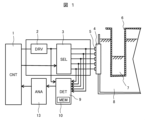
- FIG. 1 is a diagram showing part of the chemical analysis apparatus of this embodiment, showing a schematic configuration of an ultrasonic stirring mechanism.
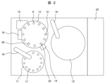
- FIG. 2 is a top view showing a schematic configuration of the chemical analysis apparatus of this embodiment.
- the chemical analyzer (also referred to as an automatic analyzer) of the present embodiment includes a specimen installation section 11, a reagent storage section 12, a reaction section 13, a stirring section 14, a measurement section 15, A cleaning unit 16 is provided, and detailed movements of each unit are controlled by an analyzer control unit 23 .
- the sample to be measured 17 installed on the sample installation unit 11 is dispensed by the sample dispensing mechanism 18 in the required amount to be used for analysis, and discharged into the reaction container 6 at the sample discharge position 20 .
- a necessary amount of reagent for analysis is dispensed from the reagent storage unit 12 by the reagent dispensing mechanism 19 and added to the reaction container 6 from which the sample to be measured 17 has been dispensed at the reagent dispensing position 21 .
- the sample and reagent discharged into the reaction container 6 move to the stirring position 22 and are stirred and mixed by the ultrasonic waves output from the piezoelectric element of the stirring section 14 . After that, the sample to be measured 17 sufficiently mixed by the stirring unit 14 undergoes component analysis in the measuring unit 15 . After the analysis is completed, the reaction container 6 is cleaned by the cleaning section 16 to prepare for another analysis.
- the stirring unit 14 includes, as main components, a stirring control unit 1, a power supply unit 2, an electrode selector 3, a piezoelectric element 4, an electrode 5, a detection unit 9, and a recording unit 10. and A plurality of electrodes 5 are arranged in the height direction of the reaction container 6 when the reaction container 6 is attached to the chemical analysis apparatus.
- the piezoelectric element 4 When a voltage is applied to the electrodes 5 of the piezoelectric element 4 from the power supply unit 2 controlled by the stirring control unit 1 via the electrode selector 3, the piezoelectric element 4 outputs ultrasonic waves, and the ultrasonic waves propagate.
- the ultrasonic wave propagates to the reaction vessel 6 through the medium 8, and the reaction liquid 7 in the reaction vessel 6 is stirred by the ultrasonic wave.
- a plurality of electrodes 5 of the piezoelectric element 4 are provided in the height direction of the reaction container 6 so that the presence or absence of the reaction liquid 7 in the reaction container 6 and the liquid level of the reaction liquid 7 can be detected.
- An electrode 5 to be measured is selected by the electrode selector 3, a voltage is applied to the selected electrode 5 from the power supply unit 2 via the electrode selector 3, and the piezoelectric element 4 outputs ultrasonic waves.
- the electric impedance of the piezoelectric element 4 is measured by the detection section 9 and the measurement result is recorded in the recording section 10 .
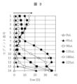
- FIG. 3 shows an example of electrical impedance measurement results.
- the vertical axis corresponds to each segment of the piezoelectric element (the position of the electrode 5 in the height direction of the reaction vessel 6), and the horizontal axis represents the electrical impedance Esw obtained from the electrical impedance Z.
- FIG. Esw is calculated by Equation (1).
- Esw is calculated by integrating the difference in the measurement results of electrical impedance for different amounts of reaction liquid over the frequency range of the measured ultrasonic waves (frequency f1 to frequency f2).
- the electrical impedance Z(f) is the measured value of each reaction liquid volume
- Zbase(f) is the measured value of a certain reaction liquid.
- FIG. 3 shows the result of calculating Zbase as the measured value when the reaction liquid volume is 0 ul.
- Segment 1 is the mouth side of reaction vessel 6 and segment 14 is the bottom side of reaction vessel 6 .
- the reaction liquid volume is 0 ul (the reaction container 6 is empty)
- the electrical impedance Esw is 0 ul in each segment because the reference and the measured value are the same.
- the electrical impedance Z changes due to the change in the acoustic impedance of the boundary where the ultrasonic wave is reflected.
- the applied electrical impedance Esw also changes.
- segment 14 As shown by the result of segment 14, as the amount of the reaction liquid increases, the amount of the reaction liquid that fills the boundary of the reflection of the ultrasonic wave also changes, and the amount of change in the electrical impedance Z changes stepwise. .
- the electrical impedance Esw changes even in the upper segment where the boundary of ultrasonic wave reflection is not filled with the reaction liquid. This is due to the fact that the apparent mass of the reaction container 6 changes due to the dispensing of the reaction liquid into the reaction container 6, and can be detected by using the formula (1).
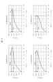
- Fig. 4 shows the relationship between the electrical impedance Z and the liquid volume. These are the results of segments 1 to 4 when there is no reaction liquid in the reaction container 6 (reaction container 6 is empty).
- the horizontal axis is the electrical impedance Esw, and the vertical axis is the liquid volume. It is a calibration curve up to 225 ul, and is the value when there is no reaction liquid in the reaction container 6 of segment 1 to segment 4.
- the correspondence between the electrical impedance Esw and the liquid volume may not be one to one. This is due to the vibration mode of the reaction vessel 6, which is a reflector of ultrasonic waves, and is because the electrical impedance Esw does not monotonically increase with an increase in the liquid volume.
- a candidate value for the liquid volume is obtained from the electrical impedance Esw measured in each segment, and the liquid volume is estimated by combining the liquid volume obtained from the candidate values. For example, a candidate value with a small variance or standard deviation is selected as the estimated fluid volume.
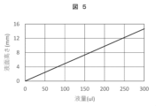
- Fig. 5 shows the relationship between the liquid volume and the liquid level. Since the reaction container 6 has a non-deformable structure such as a rectangular parallelepiped or cylindrical shape, it is possible to grasp the shape in advance, and prepare a calibration curve of the height of the liquid surface with respect to the liquid volume.
- FIG. 5 is a calibration curve of the liquid volume and the liquid level height using a cuboid reaction vessel structure as an example, and the liquid level height increases monotonically as the liquid volume increases. .
- Fig. 6 shows the estimation results of the liquid level.
- the measurement results of the electrical impedance Esw shown in FIG. 3 are displayed for each segment, the liquid volume is calculated using the relationship between the electrical impedance Esw and the liquid volume as shown in FIG. 4, and the calibration curve shown in FIG.
- the height of the liquid surface is calculated from the liquid volume and described as a candidate value.
- the frequency of the voltage applied from the power source 2 to the electrode 5 is swept, and the electrical impedance of the piezoelectric element 4 is measured by integrating the electrical impedance in the measurement range of the swept frequency. is also possible.
- “Sweep” refers to the operation of generating vibration while gradually changing the voltage frequency (frequency).
- the electrical impedance measured in advance when there is no reaction liquid 7 in the reaction vessel 6 is set as a reference value, and the electrical impedance is measured by integrating the difference between the electrical impedance measured by the detector 9 and the reference value. is also possible.
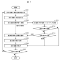
- FIG. 7 shows an operation example of the chemical analysis apparatus of this embodiment.
- step S701 a necessary amount of the sample 17 to be measured used for analysis is dispensed into the reaction container 6.
- step S702 the required amount of reagent used for analysis is dispensed into the reaction container 6.
- step S703 the sample 17 to be measured and the reaction container 6 into which the reagent has been dispensed are moved to the stirring section .
- step S711 After moving the reaction container 6 to the stirring unit 14, the electrical impedance of the piezoelectric element 4 is measured in step S711.
- step S712 the presence or absence of the reaction liquid 7 is diagnosed from the value of the electrical impedance measured in step S711, and the liquid level of the reaction liquid 7 is estimated.
- step S713 If the reaction liquid 7 is present in the reaction container 6 (yes), the process proceeds to step S713, and if there is no reaction liquid 7 (no), the process proceeds to step S706.
- step S713 the measured value of the electrical impedance is compared with a pre-measured normal value, and if normal, the process proceeds to step S704, and if abnormal, the process proceeds to step S706.
- step S704 the reaction container 6 is irradiated with ultrasonic waves to agitate the sample 17 to be measured and the reagent.
- step S705 the measurement unit 15 analyzes the components of the mixture (reaction liquid 7).
- step S706 the cleaning unit 16 cleans the reaction container 6 after the analysis is finished or after the abnormality diagnosis.
- step S707 it is confirmed whether other analysis items have been programmed, and it is determined whether to perform the next measurement or end it. If there are no other analysis items, the process is terminated, and if there are other analysis items, the process returns to step S701 and repeats the processes after step S701.
- the chemical analysis apparatus of this embodiment is a chemical analysis apparatus having an ultrasonic stirring mechanism (stirring unit 14), and the ultrasonic stirring mechanism (stirring unit 14) includes the piezoelectric element 4 and the A plurality of electrodes 5 arranged in the element 4, a power supply unit 2 that applies a voltage to the electrodes 5, a detection unit 9 that measures the electrical impedance for each of the plurality of electrodes 5 or an arbitrary combination of electrodes 5, and a detection unit It is equipped with an analysis part (stirring control part 1) that determines the liquid level in the reaction vessel 6 from the electrical impedance detected by 9, and the detection part 9 detects reactions in which two or more different amounts of liquid are dispensed.
- an analysis part (stirring control part 1) that determines the liquid level in the reaction vessel 6 from the electrical impedance detected by 9, and the detection part 9 detects reactions in which two or more different amounts of liquid are dispensed.
- the electrical impedance is measured with the container 6 facing the piezoelectric element 4, and the analysis unit (stirring control unit 1) measures the amount of change in the height direction of the reaction container 6 in the electrical impedance measured by the detection unit 9. The liquid level in the reaction container 6 is estimated.
- an electrode selector 3 connected between the power supply unit 2 and the electrodes 5 is provided, and a voltage is applied from the power supply unit 2 to the electrodes 5 selected by the electrode selector 3, The electrical impedance is measured for the electrode 5 selected by 3.
- the analysis unit (stirring control unit 1) estimates the liquid level in the reaction vessel 6 based on the preset relationship between the electrical impedance and the liquid level.
- the electrical impedance of the piezoelectric element 4 is measured and the measured value is processed, thereby using means such as a sensor for confirming the presence or absence of the reaction liquid 7 or visual observation. It is possible to estimate the presence or absence of the reaction liquid 7 and the liquid surface height without using it.
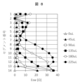
- FIG. 8 is a diagram showing an example of measurement results of electrical impedance in this example.
- the configuration of the chemical analysis apparatus and the chemical analysis method of this example are basically the same as in Example 1.
- failure diagnosis of the stirring unit 14 is further performed.
- segment 2 does not capture changes in electrical impedance with respect to changes in liquid volume. If the piezoelectric element 4 fails, the change in the liquid volume of the reaction liquid 7 in the reaction container 6 cannot be correctly detected. A failure mode in which the electrical impedance does not change.
- failure modes in which the amount of change in electrical impedance varies more than in normal conditions. In that case, failure is determined by comparison with the amount of change in electrical impedance of nearby segments.
- the timing of the failure diagnosis can be the same timing as the step of diagnosing the presence or absence of the reaction liquid 7 in step S712 of FIG. If the estimated value of the liquid level is significantly different from that of the surrounding (neighboring) segment based on the measurement result of the electrical impedance of the piezoelectric element 4, the corresponding segment is diagnosed as faulty. In this case, the presence or absence of the reaction liquid 7 is diagnosed based on the measurement results of the segments other than the segment diagnosed as faulty.
- the analysis unit (stirring control unit 1) diagnoses the failure of the piezoelectric element 4 based on the preset relationship between the electrical impedance and the liquid level.
- the electrical impedance of the piezoelectric element 4 is measured and the measured value is processed, thereby using means such as a sensor for confirming the presence or absence of the reaction liquid 7 or visual observation. It is possible to estimate the presence or absence of the reaction liquid 7 and the liquid surface height without using it. Furthermore, it is possible to easily perform abnormality diagnosis of the piezoelectric element 4 which is an ultrasonic element.
- the present invention is not limited to the above-described embodiments, and includes various modifications.
- the above-described embodiments have been described in detail in order to explain the present invention in an easy-to-understand manner, and are not necessarily limited to those having all the described configurations.
- it is possible to replace part of the configuration of one embodiment with the configuration of another embodiment and it is also possible to add the configuration of another embodiment to the configuration of one embodiment.
Landscapes
- Physics & Mathematics (AREA)
- Health & Medical Sciences (AREA)
- Life Sciences & Earth Sciences (AREA)
- Chemical & Material Sciences (AREA)
- Analytical Chemistry (AREA)
- Biochemistry (AREA)
- General Health & Medical Sciences (AREA)
- General Physics & Mathematics (AREA)
- Immunology (AREA)
- Pathology (AREA)
- Automatic Analysis And Handling Materials Therefor (AREA)
- Sampling And Sample Adjustment (AREA)
- Investigating Or Analyzing Materials By The Use Of Electric Means (AREA)
Abstract
L'invention concerne un appareil d'analyse chimique doté d'une fonction d'agitation permettant d'agiter, à l'aide d'un élément ultrasonore, un réactif ou autre et un échantillon à mesurer, et qui permet de déduire la présence ou l'absence d'un liquide de réaction et d'estimer la quantité de liquide de réaction sans utiliser de moyens tels qu'un capteur et une inspection visuelle. Cet appareil d'analyse chimique est doté d'un mécanisme d'agitation ultrasonore et est caractérisé par le fait que le mécanisme d'agitation ultrasonore comprend : un élément piézoélectrique; plusieurs électrodes connectées à l'élément piézoélectrique; une source d'énergie pour appliquer une tension aux électrodes; une unité de détection pour mesurer l'impédance électrique pour chacune des électrodes ou pour toute combinaison d'électrodes; et une unité d'analyse pour déterminer la quantité de liquide dans une cuve de réaction à partir de l'impédance électrique détectée par l'unité de détection. L'appareil d'analyse chimique est caractérisé par le fait que l'unité de détection mesure l'impédance électrique dans un état où une cuve de réaction contenant deux ou plusieurs quantités différentes de liquide fait face à l'élément piézoélectrique, et l'unité d'analyse estime la quantité de liquide dans la cuve de réaction sur la base de la variation de l'impédance électrique mesurée par l'unité de détection.
Applications Claiming Priority (2)
| Application Number | Priority Date | Filing Date | Title |
|---|---|---|---|
| JP2021-214289 | 2021-12-28 | ||
| JP2021214289A JP2023097912A (ja) | 2021-12-28 | 2021-12-28 | 化学分析装置、化学分析方法 |
Publications (1)
| Publication Number | Publication Date |
|---|---|
| WO2023127355A1 true WO2023127355A1 (fr) | 2023-07-06 |
Family
ID=86998849
Family Applications (1)
| Application Number | Title | Priority Date | Filing Date |
|---|---|---|---|
| PCT/JP2022/043104 WO2023127355A1 (fr) | 2021-12-28 | 2022-11-22 | Appareil et procédé d'analyse chimique |
Country Status (2)
| Country | Link |
|---|---|
| JP (1) | JP2023097912A (fr) |
| WO (1) | WO2023127355A1 (fr) |
Citations (6)
| Publication number | Priority date | Publication date | Assignee | Title |
|---|---|---|---|---|
| JP2000338113A (ja) * | 1999-05-27 | 2000-12-08 | Hitachi Ltd | 化学分析装置 |
| WO2009011314A1 (fr) * | 2007-07-18 | 2009-01-22 | Olympus Corporation | Appareil d'analyse et son procédé de suppression d'anomalies |
| JP2009036666A (ja) * | 2007-08-02 | 2009-02-19 | Olympus Corp | 液量検出装置及び自動分析装置 |
| JP2010096638A (ja) * | 2008-10-17 | 2010-04-30 | Hitachi High-Technologies Corp | 自動分析装置 |
| JP2019124608A (ja) * | 2018-01-17 | 2019-07-25 | 株式会社日立ハイテクノロジーズ | 化学分析装置、及び、当該化学分析装置に用いる音波攪拌機構 |
| WO2021256027A1 (fr) * | 2020-06-18 | 2021-12-23 | 株式会社日立ハイテク | Appareil d'analyse chimique automatique et dispositif de spectrométrie d'impédance électrique |
-
2021
- 2021-12-28 JP JP2021214289A patent/JP2023097912A/ja active Pending
-
2022
- 2022-11-22 WO PCT/JP2022/043104 patent/WO2023127355A1/fr active Search and Examination
Patent Citations (6)
| Publication number | Priority date | Publication date | Assignee | Title |
|---|---|---|---|---|
| JP2000338113A (ja) * | 1999-05-27 | 2000-12-08 | Hitachi Ltd | 化学分析装置 |
| WO2009011314A1 (fr) * | 2007-07-18 | 2009-01-22 | Olympus Corporation | Appareil d'analyse et son procédé de suppression d'anomalies |
| JP2009036666A (ja) * | 2007-08-02 | 2009-02-19 | Olympus Corp | 液量検出装置及び自動分析装置 |
| JP2010096638A (ja) * | 2008-10-17 | 2010-04-30 | Hitachi High-Technologies Corp | 自動分析装置 |
| JP2019124608A (ja) * | 2018-01-17 | 2019-07-25 | 株式会社日立ハイテクノロジーズ | 化学分析装置、及び、当該化学分析装置に用いる音波攪拌機構 |
| WO2021256027A1 (fr) * | 2020-06-18 | 2021-12-23 | 株式会社日立ハイテク | Appareil d'analyse chimique automatique et dispositif de spectrométrie d'impédance électrique |
Also Published As
| Publication number | Publication date |
|---|---|
| JP2023097912A (ja) | 2023-07-10 |
Similar Documents
| Publication | Publication Date | Title |
|---|---|---|
| JP5140497B2 (ja) | 分析装置及び分析方法 | |
| JP5277214B2 (ja) | 自動分析装置 | |
| JP2008058163A (ja) | 自動分析装置 | |
| US20100122586A1 (en) | Automatic analyzer and dispensing method | |
| EP2172779B1 (fr) | Appareil d'analyse et son procédé de suppression d'anomalies | |
| WO2021256027A1 (fr) | Appareil d'analyse chimique automatique et dispositif de spectrométrie d'impédance électrique | |
| JP5063620B2 (ja) | 自動分析装置 | |
| JP2010096638A (ja) | 自動分析装置 | |
| WO2023127355A1 (fr) | Appareil et procédé d'analyse chimique | |
| JP2009031203A (ja) | 自動分析装置 | |
| JP6224371B2 (ja) | 自動分析装置 | |
| JP2007040843A (ja) | 自動分析装置 | |
| US7802479B2 (en) | Stirring apparatus, abnormality determining method of same, and analyzer | |
| JP2001188070A (ja) | 自動分析装置及び自動分析方法 | |
| JP7296865B2 (ja) | 化学分析装置 | |
| JP5219461B2 (ja) | 攪拌判定方法及び分析装置 | |
| JP2009162585A (ja) | 分析装置及び分析方法 | |
| JP2010217050A (ja) | 自動分析装置とその液体試料の温度上昇抑制方法 | |
| JP4855978B2 (ja) | 自動分析装置 | |
| WO2023074358A1 (fr) | Dispositif d'analyse automatisé et procédé de détermination d'anomalie associé | |
| JP2008268079A (ja) | 液面検知装置及び自動分析装置 | |
| WO2022224604A1 (fr) | Dispositif d'analyse automatique et procédé d'analyse | |
| JP2018091743A (ja) | 臨床検査装置 | |
| JP2008286587A (ja) | 分注装置及び自動分析装置 | |
| JP2009042048A (ja) | 自動分析装置および自動分析装置の攪拌良否判定方法 |
Legal Events
| Date | Code | Title | Description |
|---|---|---|---|
| 121 | Ep: the epo has been informed by wipo that ep was designated in this application |
Ref document number: 22915586 Country of ref document: EP Kind code of ref document: A1 |
|
| DPE1 | Request for preliminary examination filed after expiration of 19th month from priority date (pct application filed from 20040101) |