WO2023127355A1 - 化学分析装置、化学分析方法 - Google Patents
化学分析装置、化学分析方法 Download PDFInfo
- Publication number
- WO2023127355A1 WO2023127355A1 PCT/JP2022/043104 JP2022043104W WO2023127355A1 WO 2023127355 A1 WO2023127355 A1 WO 2023127355A1 JP 2022043104 W JP2022043104 W JP 2022043104W WO 2023127355 A1 WO2023127355 A1 WO 2023127355A1
- Authority
- WO
- WIPO (PCT)
- Prior art keywords
- chemical analysis
- electrical impedance
- reaction vessel
- piezoelectric element
- measured
- Prior art date
Links
- 238000004458 analytical method Methods 0.000 title claims abstract description 69
- 239000000126 substance Substances 0.000 title claims abstract description 46
- 238000009614 chemical analysis method Methods 0.000 title claims description 19
- 238000006243 chemical reaction Methods 0.000 claims abstract description 83
- 239000007788 liquid Substances 0.000 claims abstract description 59
- 238000003756 stirring Methods 0.000 claims abstract description 55
- 239000003153 chemical reaction reagent Substances 0.000 claims abstract description 26
- 238000001514 detection method Methods 0.000 claims abstract description 17
- 238000005259 measurement Methods 0.000 claims description 16
- 238000003745 diagnosis Methods 0.000 claims description 6
- 239000012295 chemical reaction liquid Substances 0.000 abstract description 40
- 238000011179 visual inspection Methods 0.000 abstract 1
- 238000000034 method Methods 0.000 description 17
- 238000010586 diagram Methods 0.000 description 7
- 230000005856 abnormality Effects 0.000 description 5
- 238000004140 cleaning Methods 0.000 description 5
- 238000011088 calibration curve Methods 0.000 description 4
- 238000009434 installation Methods 0.000 description 3
- 230000000007 visual effect Effects 0.000 description 3
- 230000002159 abnormal effect Effects 0.000 description 2
- 238000005406 washing Methods 0.000 description 2
- 238000013019 agitation Methods 0.000 description 1
- 238000011109 contamination Methods 0.000 description 1
- 230000000694 effects Effects 0.000 description 1
- 238000005516 engineering process Methods 0.000 description 1
- 239000012530 fluid Substances 0.000 description 1
- 238000002847 impedance measurement Methods 0.000 description 1
- 230000001678 irradiating effect Effects 0.000 description 1
- 239000000203 mixture Substances 0.000 description 1
- 238000012986 modification Methods 0.000 description 1
- 230000004048 modification Effects 0.000 description 1
- 238000012544 monitoring process Methods 0.000 description 1
- 230000000644 propagated effect Effects 0.000 description 1
- XLYOFNOQVPJJNP-UHFFFAOYSA-N water Substances O XLYOFNOQVPJJNP-UHFFFAOYSA-N 0.000 description 1
Images

Classifications
-
- G—PHYSICS
- G01—MEASURING; TESTING
- G01N—INVESTIGATING OR ANALYSING MATERIALS BY DETERMINING THEIR CHEMICAL OR PHYSICAL PROPERTIES
- G01N1/00—Sampling; Preparing specimens for investigation
- G01N1/28—Preparing specimens for investigation including physical details of (bio-)chemical methods covered elsewhere, e.g. G01N33/50, C12Q
- G01N1/38—Diluting, dispersing or mixing samples
-
- G—PHYSICS
- G01—MEASURING; TESTING
- G01N—INVESTIGATING OR ANALYSING MATERIALS BY DETERMINING THEIR CHEMICAL OR PHYSICAL PROPERTIES
- G01N35/00—Automatic analysis not limited to methods or materials provided for in any single one of groups G01N1/00 - G01N33/00; Handling materials therefor
- G01N35/02—Automatic analysis not limited to methods or materials provided for in any single one of groups G01N1/00 - G01N33/00; Handling materials therefor using a plurality of sample containers moved by a conveyor system past one or more treatment or analysis stations
Definitions
- the present invention relates to the configuration of a chemical analysis apparatus and its failure diagnosis method, and more particularly to a chemical analysis apparatus having a stirring function for stirring a reagent or the like and a sample to be measured using ultrasonic waves generated by vibration of a piezoelectric element. It relates to technology that can be applied and effective.
- a stirring rod having a spatula-shaped tip is inserted into a reaction container for mixing the reagent and the sample as means for stirring the reagent and the sample to be measured.
- a method of rotating or reciprocating is used.
- These stirring means using ultrasonic waves use ultrasonic waves to generate fluidity in the specimen and the reagent to mix and stir the reaction solution without using a stirring rod or the like. It is a technique that can avoid carryover of specimens and reagents caused by such a phenomenon, and contamination of washing water into the reaction vessel.
- the piezoelectric element itself may be damaged due to the heat generated by the piezoelectric element.
- the non-operating time of the stirring mechanism is used to detect an abnormality in the piezoelectric element, predict a failure in advance, and issue a warning, thereby preventing an unexpected stoppage of the device.
- the temperature information of the piezoelectric element or the piezoelectric element drive circuit in the normal operation state is stored, and compared with the temperature information during the operation of the stirring mechanism, the piezoelectric element or the piezoelectric element is driven. The circuit is judged to be abnormal.
- Patent Literature 1 describes damage to the piezoelectric element when ultrasonic waves are oscillated in a state where the reaction vessel is not attached or the reaction vessel is empty as described above. , there is no mention of how to solve it.
- Patent Document 3 describes a method of estimating the surrounding situation before outputting a sound wave from the piezoelectric element and stopping the output of the sound wave when an abnormality is detected to improve the reliability of the piezoelectric element.
- a stirring unit that stirs a reagent discharged into a reaction container and a sample to be measured by sound waves using a piezoelectric element as a sound source, a power supply unit that can change the voltage and frequency for driving the piezoelectric element, and a reagent.
- the electric impedance is obtained from the voltage or current waveform that drives the piezoelectric element. It is described that the surrounding conditions of the piezoelectric element at the time of sound wave output are estimated by measuring .
- the piezoelectric element itself which is a sound source, is used as a sensor, so that sound waves can be emitted from the piezoelectric element without complicating the configuration. It is possible to confirm the presence or absence of the reaction container and the reaction liquid, or the presence or absence of the medium through which the sound wave propagates, when the sound is generated.
- Patent Document 3 is a method for detecting temperature changes in a medium through which sound waves propagate from electrical impedance changes in piezoelectric elements.
- Patent Document 3 since the acoustic impedance at the boundary of the ultrasonic reflector differs depending on the presence or absence of the reaction liquid in the reaction vessel, the frequency at which the electrical impedance becomes the minimum and the amount of change in the electrical impedance at that time are measured. It is possible to confirm the presence or absence of a reaction liquid or the presence or absence of a medium through which sound waves are transmitted. Also, it is described that the temperature change of the medium through which the sound wave propagates can be detected from the electrical impedance change of the piezoelectric element.
- Patent Document 4 does not describe damage to the piezoelectric element when ultrasonic waves are oscillated in a state where the reaction container is not attached or the reaction container is empty as described above.
- an object of the present invention is to provide a chemical analysis apparatus having a stirring function that uses an ultrasonic element to stir a reagent or the like and a sample to be measured.
- An object of the present invention is to provide a chemical analysis apparatus capable of estimating the presence/absence and the liquid level of a reaction liquid, and a chemical analysis method using the same.
- the present invention provides a chemical analysis apparatus having an ultrasonic stirring mechanism, wherein the ultrasonic stirring mechanism comprises a piezoelectric element, a plurality of electrodes arranged on the piezoelectric element, and a A power source that applies a voltage, a detector that measures electrical impedance for each of the plurality of electrodes or any combination of electrodes, and a liquid level in the reaction vessel that is determined from the electrical impedance detected by the detector. and an analysis unit that measures electrical impedance in a state in which two or more reaction containers dispensed with different amounts of liquid are opposed to the piezoelectric element, and the analysis unit measures the detection The liquid level in the reaction vessel is estimated based on the amount of change in electrical impedance measured in the section.
- the present invention includes the steps of: (a) dispensing a sample to be measured into a reaction vessel; (b) dispensing a reagent into the reaction vessel; (c) moving the reaction vessel to a stirring section; (d) measuring the electrical impedance with the container facing the piezoelectric element of the stirring unit; a step of estimating.
- a chemical analyzer equipped with a stirring function for stirring a reagent or the like and a sample to be measured using an ultrasonic element
- presence or absence of a reaction solution can be determined without using means such as a sensor or visual observation.
- a chemical analysis apparatus capable of estimating the liquid level of a reaction liquid and a chemical analysis method using the same can be realized.
- FIG. 1 is a schematic configuration diagram of an ultrasonic stirring mechanism according to Example 1 of the present invention
- FIG. 1 is a schematic configuration diagram of a chemical analysis apparatus according to Example 1 of the present invention
- FIG. 4 is a diagram showing an example of a measurement result of electrical impedance according to Example 1 of the present invention
- FIG. 4 is a diagram showing an example of the relationship between electrical impedance and liquid volume according to Example 1 of the present invention
- 4 is a flow chart showing an operation example of the chemical analysis apparatus according to Example 1 of the present invention
- FIG. 10 is a diagram showing an example of a measurement result of electrical impedance according to Example 2 of the present invention
- Example 1 of the present invention A chemical analysis apparatus and a chemical analysis method according to Example 1 of the present invention will be described with reference to FIGS.
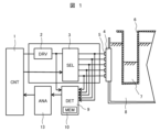
- FIG. 1 is a diagram showing part of the chemical analysis apparatus of this embodiment, showing a schematic configuration of an ultrasonic stirring mechanism.
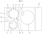
- FIG. 2 is a top view showing a schematic configuration of the chemical analysis apparatus of this embodiment.
- the chemical analyzer (also referred to as an automatic analyzer) of the present embodiment includes a specimen installation section 11, a reagent storage section 12, a reaction section 13, a stirring section 14, a measurement section 15, A cleaning unit 16 is provided, and detailed movements of each unit are controlled by an analyzer control unit 23 .
- the sample to be measured 17 installed on the sample installation unit 11 is dispensed by the sample dispensing mechanism 18 in the required amount to be used for analysis, and discharged into the reaction container 6 at the sample discharge position 20 .
- a necessary amount of reagent for analysis is dispensed from the reagent storage unit 12 by the reagent dispensing mechanism 19 and added to the reaction container 6 from which the sample to be measured 17 has been dispensed at the reagent dispensing position 21 .
- the sample and reagent discharged into the reaction container 6 move to the stirring position 22 and are stirred and mixed by the ultrasonic waves output from the piezoelectric element of the stirring section 14 . After that, the sample to be measured 17 sufficiently mixed by the stirring unit 14 undergoes component analysis in the measuring unit 15 . After the analysis is completed, the reaction container 6 is cleaned by the cleaning section 16 to prepare for another analysis.
- the stirring unit 14 includes, as main components, a stirring control unit 1, a power supply unit 2, an electrode selector 3, a piezoelectric element 4, an electrode 5, a detection unit 9, and a recording unit 10. and A plurality of electrodes 5 are arranged in the height direction of the reaction container 6 when the reaction container 6 is attached to the chemical analysis apparatus.
- the piezoelectric element 4 When a voltage is applied to the electrodes 5 of the piezoelectric element 4 from the power supply unit 2 controlled by the stirring control unit 1 via the electrode selector 3, the piezoelectric element 4 outputs ultrasonic waves, and the ultrasonic waves propagate.
- the ultrasonic wave propagates to the reaction vessel 6 through the medium 8, and the reaction liquid 7 in the reaction vessel 6 is stirred by the ultrasonic wave.
- a plurality of electrodes 5 of the piezoelectric element 4 are provided in the height direction of the reaction container 6 so that the presence or absence of the reaction liquid 7 in the reaction container 6 and the liquid level of the reaction liquid 7 can be detected.
- An electrode 5 to be measured is selected by the electrode selector 3, a voltage is applied to the selected electrode 5 from the power supply unit 2 via the electrode selector 3, and the piezoelectric element 4 outputs ultrasonic waves.
- the electric impedance of the piezoelectric element 4 is measured by the detection section 9 and the measurement result is recorded in the recording section 10 .
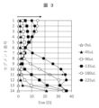
- FIG. 3 shows an example of electrical impedance measurement results.
- the vertical axis corresponds to each segment of the piezoelectric element (the position of the electrode 5 in the height direction of the reaction vessel 6), and the horizontal axis represents the electrical impedance Esw obtained from the electrical impedance Z.
- FIG. Esw is calculated by Equation (1).
- Esw is calculated by integrating the difference in the measurement results of electrical impedance for different amounts of reaction liquid over the frequency range of the measured ultrasonic waves (frequency f1 to frequency f2).
- the electrical impedance Z(f) is the measured value of each reaction liquid volume
- Zbase(f) is the measured value of a certain reaction liquid.
- FIG. 3 shows the result of calculating Zbase as the measured value when the reaction liquid volume is 0 ul.
- Segment 1 is the mouth side of reaction vessel 6 and segment 14 is the bottom side of reaction vessel 6 .
- the reaction liquid volume is 0 ul (the reaction container 6 is empty)
- the electrical impedance Esw is 0 ul in each segment because the reference and the measured value are the same.
- the electrical impedance Z changes due to the change in the acoustic impedance of the boundary where the ultrasonic wave is reflected.
- the applied electrical impedance Esw also changes.
- segment 14 As shown by the result of segment 14, as the amount of the reaction liquid increases, the amount of the reaction liquid that fills the boundary of the reflection of the ultrasonic wave also changes, and the amount of change in the electrical impedance Z changes stepwise. .
- the electrical impedance Esw changes even in the upper segment where the boundary of ultrasonic wave reflection is not filled with the reaction liquid. This is due to the fact that the apparent mass of the reaction container 6 changes due to the dispensing of the reaction liquid into the reaction container 6, and can be detected by using the formula (1).
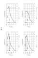
- Fig. 4 shows the relationship between the electrical impedance Z and the liquid volume. These are the results of segments 1 to 4 when there is no reaction liquid in the reaction container 6 (reaction container 6 is empty).
- the horizontal axis is the electrical impedance Esw, and the vertical axis is the liquid volume. It is a calibration curve up to 225 ul, and is the value when there is no reaction liquid in the reaction container 6 of segment 1 to segment 4.
- the correspondence between the electrical impedance Esw and the liquid volume may not be one to one. This is due to the vibration mode of the reaction vessel 6, which is a reflector of ultrasonic waves, and is because the electrical impedance Esw does not monotonically increase with an increase in the liquid volume.
- a candidate value for the liquid volume is obtained from the electrical impedance Esw measured in each segment, and the liquid volume is estimated by combining the liquid volume obtained from the candidate values. For example, a candidate value with a small variance or standard deviation is selected as the estimated fluid volume.
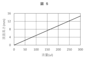
- Fig. 5 shows the relationship between the liquid volume and the liquid level. Since the reaction container 6 has a non-deformable structure such as a rectangular parallelepiped or cylindrical shape, it is possible to grasp the shape in advance, and prepare a calibration curve of the height of the liquid surface with respect to the liquid volume.
- FIG. 5 is a calibration curve of the liquid volume and the liquid level height using a cuboid reaction vessel structure as an example, and the liquid level height increases monotonically as the liquid volume increases. .
- Fig. 6 shows the estimation results of the liquid level.
- the measurement results of the electrical impedance Esw shown in FIG. 3 are displayed for each segment, the liquid volume is calculated using the relationship between the electrical impedance Esw and the liquid volume as shown in FIG. 4, and the calibration curve shown in FIG.
- the height of the liquid surface is calculated from the liquid volume and described as a candidate value.
- the frequency of the voltage applied from the power source 2 to the electrode 5 is swept, and the electrical impedance of the piezoelectric element 4 is measured by integrating the electrical impedance in the measurement range of the swept frequency. is also possible.
- “Sweep” refers to the operation of generating vibration while gradually changing the voltage frequency (frequency).
- the electrical impedance measured in advance when there is no reaction liquid 7 in the reaction vessel 6 is set as a reference value, and the electrical impedance is measured by integrating the difference between the electrical impedance measured by the detector 9 and the reference value. is also possible.
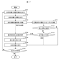
- FIG. 7 shows an operation example of the chemical analysis apparatus of this embodiment.
- step S701 a necessary amount of the sample 17 to be measured used for analysis is dispensed into the reaction container 6.
- step S702 the required amount of reagent used for analysis is dispensed into the reaction container 6.
- step S703 the sample 17 to be measured and the reaction container 6 into which the reagent has been dispensed are moved to the stirring section .
- step S711 After moving the reaction container 6 to the stirring unit 14, the electrical impedance of the piezoelectric element 4 is measured in step S711.
- step S712 the presence or absence of the reaction liquid 7 is diagnosed from the value of the electrical impedance measured in step S711, and the liquid level of the reaction liquid 7 is estimated.
- step S713 If the reaction liquid 7 is present in the reaction container 6 (yes), the process proceeds to step S713, and if there is no reaction liquid 7 (no), the process proceeds to step S706.
- step S713 the measured value of the electrical impedance is compared with a pre-measured normal value, and if normal, the process proceeds to step S704, and if abnormal, the process proceeds to step S706.
- step S704 the reaction container 6 is irradiated with ultrasonic waves to agitate the sample 17 to be measured and the reagent.
- step S705 the measurement unit 15 analyzes the components of the mixture (reaction liquid 7).
- step S706 the cleaning unit 16 cleans the reaction container 6 after the analysis is finished or after the abnormality diagnosis.
- step S707 it is confirmed whether other analysis items have been programmed, and it is determined whether to perform the next measurement or end it. If there are no other analysis items, the process is terminated, and if there are other analysis items, the process returns to step S701 and repeats the processes after step S701.
- the chemical analysis apparatus of this embodiment is a chemical analysis apparatus having an ultrasonic stirring mechanism (stirring unit 14), and the ultrasonic stirring mechanism (stirring unit 14) includes the piezoelectric element 4 and the A plurality of electrodes 5 arranged in the element 4, a power supply unit 2 that applies a voltage to the electrodes 5, a detection unit 9 that measures the electrical impedance for each of the plurality of electrodes 5 or an arbitrary combination of electrodes 5, and a detection unit It is equipped with an analysis part (stirring control part 1) that determines the liquid level in the reaction vessel 6 from the electrical impedance detected by 9, and the detection part 9 detects reactions in which two or more different amounts of liquid are dispensed.
- an analysis part (stirring control part 1) that determines the liquid level in the reaction vessel 6 from the electrical impedance detected by 9, and the detection part 9 detects reactions in which two or more different amounts of liquid are dispensed.
- the electrical impedance is measured with the container 6 facing the piezoelectric element 4, and the analysis unit (stirring control unit 1) measures the amount of change in the height direction of the reaction container 6 in the electrical impedance measured by the detection unit 9. The liquid level in the reaction container 6 is estimated.
- an electrode selector 3 connected between the power supply unit 2 and the electrodes 5 is provided, and a voltage is applied from the power supply unit 2 to the electrodes 5 selected by the electrode selector 3, The electrical impedance is measured for the electrode 5 selected by 3.
- the analysis unit (stirring control unit 1) estimates the liquid level in the reaction vessel 6 based on the preset relationship between the electrical impedance and the liquid level.
- the electrical impedance of the piezoelectric element 4 is measured and the measured value is processed, thereby using means such as a sensor for confirming the presence or absence of the reaction liquid 7 or visual observation. It is possible to estimate the presence or absence of the reaction liquid 7 and the liquid surface height without using it.
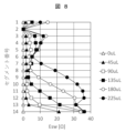
- FIG. 8 is a diagram showing an example of measurement results of electrical impedance in this example.
- the configuration of the chemical analysis apparatus and the chemical analysis method of this example are basically the same as in Example 1.
- failure diagnosis of the stirring unit 14 is further performed.
- segment 2 does not capture changes in electrical impedance with respect to changes in liquid volume. If the piezoelectric element 4 fails, the change in the liquid volume of the reaction liquid 7 in the reaction container 6 cannot be correctly detected. A failure mode in which the electrical impedance does not change.
- failure modes in which the amount of change in electrical impedance varies more than in normal conditions. In that case, failure is determined by comparison with the amount of change in electrical impedance of nearby segments.
- the timing of the failure diagnosis can be the same timing as the step of diagnosing the presence or absence of the reaction liquid 7 in step S712 of FIG. If the estimated value of the liquid level is significantly different from that of the surrounding (neighboring) segment based on the measurement result of the electrical impedance of the piezoelectric element 4, the corresponding segment is diagnosed as faulty. In this case, the presence or absence of the reaction liquid 7 is diagnosed based on the measurement results of the segments other than the segment diagnosed as faulty.
- the analysis unit (stirring control unit 1) diagnoses the failure of the piezoelectric element 4 based on the preset relationship between the electrical impedance and the liquid level.
- the electrical impedance of the piezoelectric element 4 is measured and the measured value is processed, thereby using means such as a sensor for confirming the presence or absence of the reaction liquid 7 or visual observation. It is possible to estimate the presence or absence of the reaction liquid 7 and the liquid surface height without using it. Furthermore, it is possible to easily perform abnormality diagnosis of the piezoelectric element 4 which is an ultrasonic element.
- the present invention is not limited to the above-described embodiments, and includes various modifications.
- the above-described embodiments have been described in detail in order to explain the present invention in an easy-to-understand manner, and are not necessarily limited to those having all the described configurations.
- it is possible to replace part of the configuration of one embodiment with the configuration of another embodiment and it is also possible to add the configuration of another embodiment to the configuration of one embodiment.
Landscapes
- Physics & Mathematics (AREA)
- Health & Medical Sciences (AREA)
- Life Sciences & Earth Sciences (AREA)
- Chemical & Material Sciences (AREA)
- Analytical Chemistry (AREA)
- Biochemistry (AREA)
- General Health & Medical Sciences (AREA)
- General Physics & Mathematics (AREA)
- Immunology (AREA)
- Pathology (AREA)
- Automatic Analysis And Handling Materials Therefor (AREA)
- Sampling And Sample Adjustment (AREA)
- Investigating Or Analyzing Materials By The Use Of Electric Means (AREA)
Abstract
超音波素子を利用して試薬等と被測定検体との攪拌を行う攪拌機能を備えた化学分析装置において、センサや目視等の手段を使用することなく反応液の有無および反応液の液面高さを推定可能な化学分析装置を提供する。超音波攪拌機構を有する化学分析装置であって、前記超音波攪拌機構は、圧電素子と、前記圧電素子に複数配置された電極と、前記電極に電圧を印加する電源部と、前記複数の電極毎または任意の組合せの電極に対して電気インピーダンスを測定する検出部と、前記検出部で検出した電気インピーダンスより反応容器内の液面高さを判断する分析部と、を備え、前記検出部は、2つ以上の異なる液量が分注された反応容器を前記圧電素子に対面させた状態で電気インピーダンスを測定し、前記分析部は、前記検出部で測定した電気インピーダンスの変化量に基づいて前記反応容器内の液面高さを推定することを特徴とする。
Description
本発明は、化学分析装置の構成とその故障診断方法に係り、特に、圧電素子の振動による超音波を利用して試薬等と被測定検体との攪拌を行う攪拌機能を備えた化学分析装置に適用して有効な技術に関する。
従来の化学分析装置では、試薬と被測定検体との攪拌手段として、試薬を検体に混合するためにへら状の先端を有する攪拌棒を試薬と検体を混合する反応容器内に挿入し、攪拌棒を回転または往復する方式が用いられている。
このような化学分析装置では、攪拌棒に付着した試薬または検体が、次の分析結果に影響を与えるキャリーオーバーと呼ばれる現象が起こり得るため、攪拌棒を洗浄する機構が必要である。
この問題を解決するため、例えば特許文献1から特許文献4のように、検体の分析に必要な試薬と検体を混合する攪拌手段に、超音波を反応容器内の反応液に照射する方法を用いた自動分析装置がある。
これらの超音波を用いた攪拌手段は、攪拌棒などを媒介せずに、超音波によって検体と試薬に流動を発生させて反応液を混合し攪拌する方式であるため、攪拌棒を用いることに起因する検体及び試薬のキャリーオーバーや、反応容器内への洗浄水の混入を回避することが可能な技術である。
上記特許文献1から特許文献4のように、攪拌手段に超音波を用いた場合、例えば、攪拌すべき反応容器が装着されていない状態や反応容器が空の状態で超音波を発振した際に、反応容器収納部の周辺部から反射される意図しない超音波により、超音波の発振源である圧電素子を損傷する可能性がある。
また、空気中に超音波を繰り返し発振すると、圧電素子の発熱により、圧電素子自体が損傷する可能性もある。
そこで、圧電素子から超音波を発振する際に、反応容器の有無或いは超音波が伝搬される媒体の有無を確認する方法として、反応容器や媒体を検知するセンサを設ける方法がある。
しかし、この方法では、機構の複雑化による信頼性の低下やコスト上昇が懸念される。
上記特許文献1では、攪拌機構の非動作時間を使用して、ピエゾ素子の異常を検出し、事前に故障の予想を行い警告することにより、装置の不測の停止を防止することができる。
また、上記特許文献2では、ピエゾ素子またはピエゾ素子駆動回路が正常動作の状態の、温度情報を記憶しておき、攪拌機構の動作中の温度情報と比較することにより、ピエゾ素子またはピエゾ素子駆動回路の異常判断している。
しかしながら、特許文献1及び特許文献2のいずれにも、上述したような反応容器が装着されていない状態や反応容器が空の状態で超音波を発振した際の圧電素子の損傷に関するする記載はなく、それを解決する方法についても触れられていない。
また、上記特許文献3には、圧電素子から音波を出力する前に周辺状況を推定し、異常を検出したときには音波の出力を停止して、圧電素子の信頼性を向上する方法の記載がある。
特許文献3では、圧電素子を音源とする音波により反応容器に吐出した試薬と被測定検体とを攪拌する攪拌部と、上記圧電素子を駆動する電圧及び周波数が変更可能な電源部と、試薬と被測定検 体を反応させて成分分析を行う分析部と、上記攪拌部,電源部、及び分析部を制御する制御部を有する自動分析装置において、圧電素子を駆動する電圧或いは電流波形から電気インピーダンスを測定することにより、音波出力時の圧電素子の周辺状況を推定することが記載されている。
すなわち、圧電素子の周辺状況をモニタするためのセンサを、圧電素子と別に設けるのではなく、音源となる圧電素子そのものをセンサとして利用することにより、構成を複雑化することなく圧電素子から音波を発生する際に反応容器及び反応液の有無、或いは音波が伝搬する媒体の有無を確認することができる。
また、特許文献3は、圧電素子の電気インピーダンス変化から、音波が伝搬する媒体の温度変化を検出することができるとする方法である。
特許文献3には、反応容器内の反応液の有無によって、超音波の反射体について境界の音響インピーダンスが異なることから、電気インピーダンスの最小となる周波数およびその時の電気インピーダンスの変化量を計測して反応液の有無、或いは音波が伝達する媒体の有無を確認することができる。また、圧電素子の電気インピーダンス変化から、音波が伝達する媒体の温度変化を検出できると記載されている。
しかし、圧電素子の損傷または破損が発生した状態では、電気インピーダンスは所望の計測を行うことができず、上記の反応液の有無の確認または温度変化の検出は行えない。
そのため、圧電素子の破損がないことを別の手段で確認する必要があった。
そのため、圧電素子の破損がないことを別の手段で確認する必要があった。
また、上記特許文献4にも、上述したような反応容器が装着されていない状態や反応容器が空の状態で超音波を発振した際の圧電素子の損傷に関する記載はない。
そこで、本発明の目的は、超音波素子を利用して試薬等と被測定検体との攪拌を行う攪拌機能を備えた化学分析装置において、センサや目視等の手段を使用することなく反応液の有無および反応液の液面高さを推定可能な化学分析装置とそれを用いた化学分析方法を提供することにある。
上記課題を解決するために、本発明は、超音波攪拌機構を有する化学分析装置であって、前記超音波攪拌機構は、圧電素子と、前記圧電素子に複数配置された電極と、前記電極に電圧を印加する電源部と、前記複数の電極毎または任意の組合せの電極に対して電気インピーダンスを測定する検出部と、前記検出部で検出した電気インピーダンスより反応容器内の液面高さを判断する分析部と、を備え、前記検出部は、2つ以上の異なる液量が分注された反応容器を前記圧電素子に対面させた状態で電気インピーダンスを測定し、前記分析部は、前記検出部で測定した電気インピーダンスの変化量に基づいて前記反応容器内の液面高さを推定することを特徴とする。
また、本発明は、(a)反応容器に被測定検体を分注するステップ、(b)前記反応容器に試薬を分注するステップ、(c)前記反応容器を攪拌部へ移動し、前記反応容器を前記攪拌部の圧電素子に対面させた状態で電気インピーダンスを測定するステップ、(d)前記(c)ステップで測定した電気インピーダンスの変化量に基づいて前記反応容器内の液面高さを推定するステップ、を含むことを特徴とする化学分析方法である。
本発明によれば、超音波素子を利用して試薬等と被測定検体との攪拌を行う攪拌機能を備えた化学分析装置において、センサや目視等の手段を使用することなく反応液の有無および反応液の液面高さを推定可能な化学分析装置とそれを用いた化学分析方法を実現することができる。
これにより、化学分析装置に搭載された超音波攪拌機能の異常診断を簡便に行うことができる。
上記した以外の課題、構成及び効果は、以下の実施形態の説明により明らかにされる。
以下、図面を用いて本発明の実施例を説明する。なお、実質的に同一又は類似の構成には同一の符号を付し、説明が重複する場合には、その説明を省略する場合がある。
図1から図7を参照して、本発明の実施例1に係る化学分析装置及び化学分析方法について説明する。
図1は、本実施例の化学分析装置の一部を示す図であり、超音波攪拌機構の概略構成を示している。図2は、本実施例の化学分析装置の概略構成を示す上面図である。
本実施例の化学分析装置(自動分析装置とも呼ぶ)は、図2に示すように、検体架設部11と、試薬格納部12と、反応部13と、攪拌部14と、測定部15と、洗浄部16とを備えており、分析装置制御部23により各部の詳細な動きが制御される。
検体架設部11に架設された被測定検体17は、分析に使用される必要量を検体分注機構18により分取され、検体吐出位置20にて反応容器6に吐出される。分析に必要な量の試薬が試薬分注機構19により試薬格納部12から分取され、試薬吐出位置21にて、被測定検体17が吐出された反応容器6に添加される。
反応容器6に吐出された検体と試薬は、攪拌位置22に移動して、攪拌部14の圧電素子から出力された超音波により攪拌されて混合される。その後、攪拌部14により充分に混合された被測定検体17は、測定部15において成分分析が行われる。分析終了後の反応容器6は、洗浄部16により洗浄が実施され、再び他の分析に備える。
攪拌部14は、図1に示すように、主要な構成として、攪拌制御部1と、電源部2と、電極セレクタ3と、圧電素子4と、電極5と、検出部9と、記録部10とを備えている。
電極5は、反応容器6を化学分析装置に装着した際の反応容器6の高さ方向に複数配置されている。
電極5は、反応容器6を化学分析装置に装着した際の反応容器6の高さ方向に複数配置されている。
攪拌制御部1により制御される電源部2から、電極セレクタ3を経由して、圧電素子4の電極5に対して電圧が印加されると、圧電素子4は超音波を出力し、超音波伝播媒体8を介して反応容器6に伝播され、反応容器6内の反応液7が超音波により攪拌される。
圧電素子4の電極5は、反応容器6内の反応液7の有無、及び反応液7の液面高さを検出できるように、反応容器6の高さ方向に複数設けられている。
電極セレクタ3により、測定すべき電極5を選択し、選択した電極5に対して、電源部2から電極セレクタ3を介して電圧が印加され、圧電素子4は超音波を出力する。
この際、検出部9により、圧電素子4の電気インピーダンスを測定し、その測定結果を記録部10に記録する。
図3に、電気インピーダンスの測定結果例を示す。縦軸は圧電素子の各セグメント(反応容器6の高さ方向の電極5の位置)に対応し、横軸は電気インピーダンスZより得られる電気インピーダースEswを示す。Eswは式(1)により算出される。

反応液量の異なる電気インピーダンスの測定結果の差分を、測定した超音波の周波数範囲(周波数f1から周波数f2)で積分することでEswを算出する。
電気インピーダンスZ(f)は各反応液量の測定値であり、Zbase(f)はある反応液の測定値である。図3は、反応液量0ulの場合の測定値をZbaseとして算出した結果である。
セグメント1が反応容器6の口側であり、セグメント14が反応容器6の底側である。
反応液量0ul(反応容器6が空)の状態では、基準と測定値が同一であるため、電気インピーダンスEswは各セグメントで0ulである。
反応液量0ul(反応容器6が空)の状態では、基準と測定値が同一であるため、電気インピーダンスEswは各セグメントで0ulである。
反応容器6内に反応液を分注すると、特許文献3に記載があるように、超音波が反射する境界の音響インピーダンスが変化することから電気インピーダンスZが変化するため、式(1)より算出される電気インピーダンスEswも変化する。その変化は、セグメント14の結果で示されるように、反応液の増加に伴い、超音波の反射の境界が反応液で満たされる量も変化し、段階的に電気インピーダンスZの変化量が変化する。
一方で、超音波の反射の境界が反応液で満たされていない上部のセグメントでも電気インピーダンスEswが変化している。これは、反応容器6に反応液が分注されることで見かけ上の反応容器6の質量が変化していることによる影響であり、式(1)を用いることによって検出が可能となる。
図4に、電気インピーダンスZと液量の関係を示す。反応容器6内に反応液がない状態(反応容器6が空)でのセグメント1からセグメント4の結果である。横軸が電気インピーダンスEswであり、縦軸は液量である。225ulまでの検量線であり、セグメント1からセグメント4の反応容器6内には反応液がない状態での値である。
超音波の反射領域に反応液が充填されることによる電気インピーダンスEswの変化とは異なる。電気インピーダンスが0Ωから8Ωまでは電気インピーダンスEswと反応液は1対1対応の関係にあり、電気インピーダンスEswを算出することで液量を算出することができる。
電気インピーダンスEswが8Ω以上の場合、電気インピーダンスEswと液量の対応が1対1にならない場合がある。これは、超音波の反射体である反応容器6の振動モードに起因するもので、液量の増加に対して電気インピーダンスEswの変化が単調に増加しないためである。
その場合、各セグメントで測定した電気インピーダンスEswより液量の候補値を求め、候補値から得られる液量を組合せて液量を推定する。例えば、分散や標準偏差の小さい候補値が液量の推定値として選択される。
図5に、液量と液面高さの関係を示す。反応容器6は直方体や円柱形などの変形しない構造であるため、予め形状を把握しておくことが可能であり、液量に対して、液面の高さの検量線を作成しておく。図5は、直方体の反応容器構造を例にした液量と液面高さの検量線であり、液量の増加に対して、液面高さは単調に増加している関係となっている。
図6に、液面高さの推定結果を示す。図3に示す電気インピーダンスEswの測定結果をセグメント毎に表示し、図4で示したような電気インピーダンスEswと液量の関係を用いて液量を算出し、図5に示す検量線を用いてその液量から液面の高さを算出し、候補値として記載している。
候補1と候補2のそれぞれの標準偏差を計算し、比較して標準偏差の値の小さい候補2を反応液量と推定し、候補値の平均値を最終推定値(10.0mm)として表示している。
本実施例の化学分析装置では、電源部2から電極5に印加される電圧の周波数掃引を行い、掃引した周波数の測定範囲の電気インピーダンスを積分することで圧電素子4の電気インピーダンスを測定することも可能である。
「掃引」とは、電圧の周波数(振動数)を徐々に変化させながら振動を発生させる動作を指す。
また、予め測定した反応容器6内に反応液7がない場合の電気インピーダンスを基準値として設定し、検出部9で測定した電気インピーダンスと基準値の差分を積分することで電気インピーダンスを測定することも可能である。
図7に、本実施例の化学分析装置の動作例を示す。
先ず、ステップS701において、反応容器6に分析に使用される必要量の被測定検体17を分注する。
次に、ステップS702において、反応容器6に分析に使用される必要量の試薬を分注する。
続いて、ステップS703において、被測定検体17と試薬が分注された反応容器6を攪拌部14へ移動する。
反応容器6を攪拌部14へ移動後、ステップS711において、圧電素子4の電気インピーダンスを測定する。
次に、ステップS712において、ステップS711で測定した電気インピーダンスの値より、反応液7の有無を診断し、反応液7の液面高さを推定する。
反応容器6内に反応液7がある場合(有)は、ステップS713へ移行し、反応液7がない場合(無)は、ステップS706へ移行する。
ステップS713では、電気インピーダンスの測定値を予め測定しておいた正常値と比較して、正常な場合はステップS704へ移行し、異常な場合はステップS706へ移行する。
ステップS704では、超音波を反応容器6に照射して被測定検体17と試薬を攪拌する。
続いて、ステップS705において、測定部15により混合液(反応液7)の成分を分析する。
次に、ステップS706において、洗浄部16により、分析終了後または異常診断後の反応容器6の洗浄を行う。
最後に、ステップS707において、他の分析項目がプログラムされているかを確認し、次の測定を行うか終了するか判断する。他の分析項目が無い場合は、処理を終了し、他の分析項目が有る場合は、ステップS701に戻り、ステップS701以降の処理を繰り返す。
なお、本発明を適用しない従来の化学分析装置では、ステップS711からステップS713を経ずに、ステップS703からステップS704へ移行する。(現行の処理)
以上説明したように、本実施例の化学分析装置は、超音波攪拌機構(攪拌部14)を有する化学分析装置であって、超音波攪拌機構(攪拌部14)は、圧電素子4と、圧電素子4に複数配置された電極5と、電極5に電圧を印加する電源部2と、複数の電極5毎または任意の組合せの電極5に対して電気インピーダンスを測定する検出部9と、検出部9で検出した電気インピーダンスより反応容器6内の液面高さを判断する分析部(攪拌制御部1)を備えており、検出部9は、2つ以上の異なる液量が分注された反応容器6を圧電素子4に対面させた状態で電気インピーダンスを測定し、分析部(攪拌制御部1)は、検出部9で測定した電気インピーダンスの反応容器6の高さ方向の変化量に基づいて反応容器6内の液面高さを推定する。
以上説明したように、本実施例の化学分析装置は、超音波攪拌機構(攪拌部14)を有する化学分析装置であって、超音波攪拌機構(攪拌部14)は、圧電素子4と、圧電素子4に複数配置された電極5と、電極5に電圧を印加する電源部2と、複数の電極5毎または任意の組合せの電極5に対して電気インピーダンスを測定する検出部9と、検出部9で検出した電気インピーダンスより反応容器6内の液面高さを判断する分析部(攪拌制御部1)を備えており、検出部9は、2つ以上の異なる液量が分注された反応容器6を圧電素子4に対面させた状態で電気インピーダンスを測定し、分析部(攪拌制御部1)は、検出部9で測定した電気インピーダンスの反応容器6の高さ方向の変化量に基づいて反応容器6内の液面高さを推定する。
また、電源部2と電極5との間に接続された電極セレクタ3を備えており、電極セレクタ3により選択した電極5に対して電源部2から電圧を印加し、検出部9は、電極セレクタ3により選択した電極5に対して電気インピーダンスを測定する。
また、分析部(攪拌制御部1)は、予め設定された電気インピーダンスと液面高さの関係に基づいて反応容器6内の液面高さを推定する。
本実施例の化学分析装置及び化学分析方法によれば、圧電素子4の電気インピーダンスを測定し、測定値を処理することで、反応液7の有無を確認するセンサや目視等の手段を使用することなく反応液7の有無および液面高さを推定することが可能になる。
図8を参照して、本発明の実施例2に係る化学分析装置及び化学分析方法について説明する。図8は、本実施例の電気インピーダンスの測定結果例を示す図である。
本実施例の化学分析装置の構成と化学分析方法は、基本的に実施例1と同様である。実施例2では、さらに攪拌部14の故障診断を行う。
図8に示す電気インピーダンスの測定結果において、セグメント2では、液量の変化に対して電気インピーダンスの変化を捉えられていない。圧電素子4が故障すると、反応容器6内の反応液7の液量の変化を正しく捉えることができない。電気インピーダンスが変化しない故障モードである。
電気インピーダンスの変化量が正常状態よりも大きく変化する故障モードも存在する。
その場合、近くのセグメントの電気インピーダンスの変化量との比較により故障を判断する。
その場合、近くのセグメントの電気インピーダンスの変化量との比較により故障を判断する。
故障診断を行うタイミングは、図7のステップS712で反応液7の有無を診断するステップと同じタイミングで行うことができる。圧電素子4の電気インピーダンスの測定結果より、周囲の(近傍の)セグメントとの液面高さの推定値が大きく異なる場合、該当セグメントの故障と診断する。この場合、反応液7の有無の診断は、故障と診断されたセグメント以外のセグメントでの測定結果で行う。
但し、圧電素子4の故障を検出しているため、その後はステップS706での反応容器6の洗浄に移行することが望ましい。
以上説明したように、本実施例の化学分析装置では、分析部(攪拌制御部1)は、予め設定された電気インピーダンスと液面高さの関係に基づいて圧電素子4の故障診断を行う。
本実施例の化学分析装置及び化学分析方法によれば、圧電素子4の電気インピーダンスを測定し、測定値を処理することで、反応液7の有無を確認するセンサや目視等の手段を使用することなく反応液7の有無および液面高さを推定することが可能になる。さらに、超音波素子である圧電素子4の異常診断を簡便に行うことが可能となる。
なお、本発明は上記した実施例に限定されるものではなく、様々な変形例が含まれる。例えば、上記した実施例は本発明を分かりやすく説明するために詳細に説明したものであり、必ずしも説明した全ての構成を備えるものに限定されるものではない。また、ある実施例の構成の一部を他の実施例の構成に置き換えることが可能であり、また、ある実施例の構成に他の実施例の構成を加えることも可能である。また、各実施例の構成の一部について、他の構成の追加・削除・置換をすることが可能である。
1…攪拌制御部、2…電源部、3…電極セレクタ、4…圧電素子、5…電極、6…反応容器、7…反応液、8…超音波伝播媒体、9…検出部、10…記録部、11…検体架設部、12…試薬格納部、13…反応部、14…攪拌部、15…測定部、16…洗浄部、17…被測定検体、18…検体分注機構、19…試薬分注機構、20…検体吐出位置、21…試薬吐出位置、22…攪拌位置、23…分析装置制御部
Claims (13)
- 超音波攪拌機構を有する化学分析装置であって、
前記超音波攪拌機構は、圧電素子と、
前記圧電素子に複数配置された電極と、
前記電極に電圧を印加する電源部と、
前記複数の電極毎または任意の組合せの電極に対して電気インピーダンスを測定する検出部と、
前記検出部で検出した電気インピーダンスより反応容器内の液面高さを判断する分析部と、を備え、
前記検出部は、2つ以上の異なる液量が分注された反応容器を前記圧電素子に対面させた状態で電気インピーダンスを測定し、
前記分析部は、前記検出部で測定した電気インピーダンスの変化量に基づいて前記反応容器内の液面高さを推定することを特徴とする化学分析装置。 - 請求項1に記載の化学分析装置であって、
前記電極は、前記反応容器を前記化学分析装置に装着した際の前記反応容器の高さ方向に複数配置されていることを特徴とする化学分析装置。 - 請求項1に記載の化学分析装置であって、
前記電源部と前記電極との間に接続された電極セレクタを備え、
前記電極セレクタにより選択した電極に対して前記電源部から電圧を印加し、
前記検出部は、前記電極セレクタにより選択した電極に対して電気インピーダンスを測定することを特徴とする化学分析装置。 - 請求項1に記載の化学分析装置であって、
前記分析部は、予め設定された電気インピーダンスと液面高さの関係に基づいて前記反応容器内の液面高さを推定することを特徴とする化学分析装置。 - 請求項1に記載の化学分析装置であって、
前記分析部は、予め設定された電気インピーダンスと液面高さの関係に基づいて前記圧電素子の故障診断を行うことを特徴とする化学分析装置。 - 請求項1に記載の化学分析装置であって、
前記電源部から前記電極に印加される電圧の周波数掃引を行い、
掃引した周波数の測定範囲の電気インピーダンスを積分することで電気インピーダンスを測定することを特徴とする化学分析装置。 - 請求項1に記載の化学分析装置であって、
予め測定した反応容器内に液がない場合の電気インピーダンスを基準値とし、
前記検出部で測定した電気インピーダンスと前記基準値の差分を積分することで電気インピーダンスを測定することを特徴とする化学分析装置。 - 以下のステップを含む化学分析方法;
(a)反応容器に被測定検体を分注するステップ、
(b)前記反応容器に試薬を分注するステップ、
(c)前記反応容器を攪拌部へ移動し、前記反応容器を前記攪拌部の圧電素子に対面させた状態で電気インピーダンスを測定するステップ、
(d)前記(c)ステップで測定した電気インピーダンスの変化量に基づいて前記反応容器内の液面高さを推定するステップ。 - 請求項8に記載の化学分析方法であって、
前記(c)ステップにおいて、前記反応容器の高さ方向の複数の位置で電気インピーダンスを測定することを特徴とする化学分析方法。 - 請求項8に記載の化学分析方法であって、
予め設定された電気インピーダンスと液面高さの関係に基づいて前記反応容器内の液面高さを推定することを特徴とする化学分析方法。 - 請求項8に記載の化学分析方法であって、
予め設定された電気インピーダンスと液面高さの関係に基づいて前記圧電素子の故障診断を行うことを特徴とする化学分析方法。 - 請求項8に記載の化学分析方法であって、
前記圧電素子に印加する電圧の周波数掃引を行い、
掃引した周波数の測定範囲の電気インピーダンスを積分することで電気インピーダンスを測定することを特徴とする化学分析方法。 - 請求項8に記載の化学分析方法であって、
予め測定した反応容器内に液がない場合の電気インピーダンスを基準値とし、
前記(c)ステップで測定した電気インピーダンスと前記基準値の差分を積分することで電気インピーダンスを測定することを特徴とする化学分析方法。
Applications Claiming Priority (2)
| Application Number | Priority Date | Filing Date | Title |
|---|---|---|---|
| JP2021-214289 | 2021-12-28 | ||
| JP2021214289A JP2023097912A (ja) | 2021-12-28 | 2021-12-28 | 化学分析装置、化学分析方法 |
Publications (1)
| Publication Number | Publication Date |
|---|---|
| WO2023127355A1 true WO2023127355A1 (ja) | 2023-07-06 |
Family
ID=86998849
Family Applications (1)
| Application Number | Title | Priority Date | Filing Date |
|---|---|---|---|
| PCT/JP2022/043104 WO2023127355A1 (ja) | 2021-12-28 | 2022-11-22 | 化学分析装置、化学分析方法 |
Country Status (2)
| Country | Link |
|---|---|
| JP (1) | JP2023097912A (ja) |
| WO (1) | WO2023127355A1 (ja) |
Citations (6)
| Publication number | Priority date | Publication date | Assignee | Title |
|---|---|---|---|---|
| JP2000338113A (ja) * | 1999-05-27 | 2000-12-08 | Hitachi Ltd | 化学分析装置 |
| WO2009011314A1 (ja) * | 2007-07-18 | 2009-01-22 | Olympus Corporation | 分析装置とその異常対処方法 |
| JP2009036666A (ja) * | 2007-08-02 | 2009-02-19 | Olympus Corp | 液量検出装置及び自動分析装置 |
| JP2010096638A (ja) * | 2008-10-17 | 2010-04-30 | Hitachi High-Technologies Corp | 自動分析装置 |
| JP2019124608A (ja) * | 2018-01-17 | 2019-07-25 | 株式会社日立ハイテクノロジーズ | 化学分析装置、及び、当該化学分析装置に用いる音波攪拌機構 |
| WO2021256027A1 (ja) * | 2020-06-18 | 2021-12-23 | 株式会社日立ハイテク | 自動化学分析装置および電気インピーダンススペクトル測定器 |
-
2021
- 2021-12-28 JP JP2021214289A patent/JP2023097912A/ja active Pending
-
2022
- 2022-11-22 WO PCT/JP2022/043104 patent/WO2023127355A1/ja active Search and Examination
Patent Citations (6)
| Publication number | Priority date | Publication date | Assignee | Title |
|---|---|---|---|---|
| JP2000338113A (ja) * | 1999-05-27 | 2000-12-08 | Hitachi Ltd | 化学分析装置 |
| WO2009011314A1 (ja) * | 2007-07-18 | 2009-01-22 | Olympus Corporation | 分析装置とその異常対処方法 |
| JP2009036666A (ja) * | 2007-08-02 | 2009-02-19 | Olympus Corp | 液量検出装置及び自動分析装置 |
| JP2010096638A (ja) * | 2008-10-17 | 2010-04-30 | Hitachi High-Technologies Corp | 自動分析装置 |
| JP2019124608A (ja) * | 2018-01-17 | 2019-07-25 | 株式会社日立ハイテクノロジーズ | 化学分析装置、及び、当該化学分析装置に用いる音波攪拌機構 |
| WO2021256027A1 (ja) * | 2020-06-18 | 2021-12-23 | 株式会社日立ハイテク | 自動化学分析装置および電気インピーダンススペクトル測定器 |
Also Published As
| Publication number | Publication date |
|---|---|
| JP2023097912A (ja) | 2023-07-10 |
Similar Documents
| Publication | Publication Date | Title |
|---|---|---|
| JP5140497B2 (ja) | 分析装置及び分析方法 | |
| JP5277214B2 (ja) | 自動分析装置 | |
| JP2008058163A (ja) | 自動分析装置 | |
| US20100122586A1 (en) | Automatic analyzer and dispensing method | |
| EP2172779B1 (en) | Analyzing apparatus and its abnormality eliminating method | |
| WO2021256027A1 (ja) | 自動化学分析装置および電気インピーダンススペクトル測定器 | |
| JP5063620B2 (ja) | 自動分析装置 | |
| JP2010096638A (ja) | 自動分析装置 | |
| WO2023127355A1 (ja) | 化学分析装置、化学分析方法 | |
| JP2009031203A (ja) | 自動分析装置 | |
| JP6224371B2 (ja) | 自動分析装置 | |
| JP2007040843A (ja) | 自動分析装置 | |
| US7802479B2 (en) | Stirring apparatus, abnormality determining method of same, and analyzer | |
| JP2001188070A (ja) | 自動分析装置及び自動分析方法 | |
| JP7296865B2 (ja) | 化学分析装置 | |
| JP5219461B2 (ja) | 攪拌判定方法及び分析装置 | |
| JP2009162585A (ja) | 分析装置及び分析方法 | |
| JP2010217050A (ja) | 自動分析装置とその液体試料の温度上昇抑制方法 | |
| JP4855978B2 (ja) | 自動分析装置 | |
| WO2023074358A1 (ja) | 自動分析装置及びその異常判定方法 | |
| JP2008268079A (ja) | 液面検知装置及び自動分析装置 | |
| WO2022224604A1 (ja) | 自動分析装置及び分析方法 | |
| JP2018091743A (ja) | 臨床検査装置 | |
| JP2008286587A (ja) | 分注装置及び自動分析装置 | |
| JP2009042048A (ja) | 自動分析装置および自動分析装置の攪拌良否判定方法 |
Legal Events
| Date | Code | Title | Description |
|---|---|---|---|
| 121 | Ep: the epo has been informed by wipo that ep was designated in this application |
Ref document number: 22915586 Country of ref document: EP Kind code of ref document: A1 |
|
| DPE1 | Request for preliminary examination filed after expiration of 19th month from priority date (pct application filed from 20040101) |