WO2021255851A1 - クーラント供給機構 - Google Patents
クーラント供給機構 Download PDFInfo
- Publication number
- WO2021255851A1 WO2021255851A1 PCT/JP2020/023733 JP2020023733W WO2021255851A1 WO 2021255851 A1 WO2021255851 A1 WO 2021255851A1 JP 2020023733 W JP2020023733 W JP 2020023733W WO 2021255851 A1 WO2021255851 A1 WO 2021255851A1
- Authority
- WO
- WIPO (PCT)
- Prior art keywords
- coolant
- hole
- cutting insert
- supply mechanism
- coolant supply
- Prior art date
- Legal status (The legal status is an assumption and is not a legal conclusion. Google has not performed a legal analysis and makes no representation as to the accuracy of the status listed.)
- Ceased
Links
Images





Classifications
-
- B—PERFORMING OPERATIONS; TRANSPORTING
- B23—MACHINE TOOLS; METAL-WORKING NOT OTHERWISE PROVIDED FOR
- B23B—TURNING; BORING
- B23B27/00—Tools for turning or boring machines; Tools of a similar kind in general; Accessories therefor
- B23B27/10—Cutting tools with special provision for cooling
-
- B—PERFORMING OPERATIONS; TRANSPORTING
- B23—MACHINE TOOLS; METAL-WORKING NOT OTHERWISE PROVIDED FOR
- B23B—TURNING; BORING
- B23B27/00—Tools for turning or boring machines; Tools of a similar kind in general; Accessories therefor
- B23B27/14—Cutting tools of which the bits or tips or cutting inserts are of special material
- B23B27/141—Specially shaped plate-like cutting inserts, i.e. length greater or equal to width, width greater than or equal to thickness
- B23B27/145—Specially shaped plate-like cutting inserts, i.e. length greater or equal to width, width greater than or equal to thickness characterised by having a special shape
-
- B—PERFORMING OPERATIONS; TRANSPORTING
- B23—MACHINE TOOLS; METAL-WORKING NOT OTHERWISE PROVIDED FOR
- B23B—TURNING; BORING
- B23B27/00—Tools for turning or boring machines; Tools of a similar kind in general; Accessories therefor
- B23B27/14—Cutting tools of which the bits or tips or cutting inserts are of special material
- B23B27/16—Cutting tools of which the bits or tips or cutting inserts are of special material with exchangeable cutting bits or cutting inserts, e.g. able to be clamped
- B23B27/1603—Cutting tools of which the bits or tips or cutting inserts are of special material with exchangeable cutting bits or cutting inserts, e.g. able to be clamped with specially shaped plate-like exchangeable cutting inserts, e.g. chip-breaking groove
- B23B27/1611—Cutting tools of which the bits or tips or cutting inserts are of special material with exchangeable cutting bits or cutting inserts, e.g. able to be clamped with specially shaped plate-like exchangeable cutting inserts, e.g. chip-breaking groove characterised by having a special shape
-
- B—PERFORMING OPERATIONS; TRANSPORTING
- B23—MACHINE TOOLS; METAL-WORKING NOT OTHERWISE PROVIDED FOR
- B23B—TURNING; BORING
- B23B2200/00—Details of cutting inserts
- B23B2200/04—Overall shape
- B23B2200/0428—Lozenge
- B23B2200/0433—Lozenge rounded
-
- B—PERFORMING OPERATIONS; TRANSPORTING
- B23—MACHINE TOOLS; METAL-WORKING NOT OTHERWISE PROVIDED FOR
- B23B—TURNING; BORING
- B23B2200/00—Details of cutting inserts
- B23B2200/04—Overall shape
- B23B2200/0447—Parallelogram
- B23B2200/0452—Parallelogram rounded
-
- B—PERFORMING OPERATIONS; TRANSPORTING
- B23—MACHINE TOOLS; METAL-WORKING NOT OTHERWISE PROVIDED FOR
- B23B—TURNING; BORING
- B23B2200/00—Details of cutting inserts
- B23B2200/16—Supporting or bottom surfaces
- B23B2200/163—Supporting or bottom surfaces discontinuous
-
- B—PERFORMING OPERATIONS; TRANSPORTING
- B23—MACHINE TOOLS; METAL-WORKING NOT OTHERWISE PROVIDED FOR
- B23B—TURNING; BORING
- B23B2205/00—Fixation of cutting inserts in holders
- B23B2205/12—Seats for cutting inserts
-
- B—PERFORMING OPERATIONS; TRANSPORTING
- B23—MACHINE TOOLS; METAL-WORKING NOT OTHERWISE PROVIDED FOR
- B23B—TURNING; BORING
- B23B2226/00—Materials of tools or workpieces not comprising a metal
- B23B2226/12—Boron nitride
- B23B2226/125—Boron nitride cubic [CBN]
-
- B—PERFORMING OPERATIONS; TRANSPORTING
- B23—MACHINE TOOLS; METAL-WORKING NOT OTHERWISE PROVIDED FOR
- B23B—TURNING; BORING
- B23B2226/00—Materials of tools or workpieces not comprising a metal
- B23B2226/31—Diamond
- B23B2226/315—Diamond polycrystalline [PCD]
-
- B—PERFORMING OPERATIONS; TRANSPORTING
- B23—MACHINE TOOLS; METAL-WORKING NOT OTHERWISE PROVIDED FOR
- B23B—TURNING; BORING
- B23B2260/00—Details of constructional elements
- B23B2260/134—Spacers or shims
Definitions
- This disclosure relates to the coolant supply mechanism.
- the cutting tool described in Patent Document 1 (International Publication No. 2018/143809) has a holder, a cutting insert, and a clamp member.
- the cutting insert is located on the holder pocket.
- the clamp member is attached to the holder by a screw.
- a flow path through which coolant flows is formed inside the clamp member.
- the flow path formed inside the clamp member opens at the tip of the clamp member and forms an outlet from which the coolant is ejected.
- the clamp member fixes the cutting insert to the holder by contacting the cutting insert on the tip side.
- the coolant supply mechanism of the present disclosure is a coolant supply mechanism attached to a cutting insert.
- the cutting insert has a first bottom surface, a first upper surface opposite to the first bottom surface, and a first side surface connected to the first bottom surface and the first upper surface.
- the first upper surface is located at the corner of the first upper surface in a plan view, and is a corner portion connected to the first side surface to form a cutting edge and a central portion next to a corner portion opposite to the cutting edge in a plan view.
- the first upper surface is recessed toward the first bottom surface in the central portion.
- the coolant supply mechanism has a second bottom surface that comes into contact with the central portion when attached to the cutting insert, a second upper surface that is opposite to the second bottom surface, and a second side surface that is continuous with the second bottom surface and the second upper surface. It has a main body.
- the second side surface includes a first portion that contacts the stepped surface between the corner portion and the central portion when attached to the cutting insert, and a second portion that is closer to the second upper surface side than the first portion. It has one side.
- a first coolant hole for ejecting coolant toward the cutting edge is formed in the second portion.
- FIG. 1 is a perspective view of the cutting tool 100.
- FIG. 2 is a plan view of the cutting insert 10.
- FIG. 3 is a bottom view of the cutting insert 10.
- FIG. 4 is a side view of the cutting insert 10.
- FIG. 5 is a perspective view of the cutting insert 10 according to the modified example.
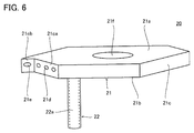
- FIG. 6 is a perspective view of the coolant supply mechanism 20.
- FIG. 7 is a plan view of the coolant supply mechanism 20.
- FIG. 8 is a side view of the coolant supply mechanism 20.
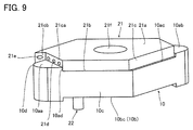
- FIG. 9 is a perspective view of the coolant supply mechanism 20 when attached to the cutting insert 10.
- FIG. 10 is a perspective view of the holder 30.
- the present disclosure provides a coolant supply mechanism capable of accurately supplying coolant to the cutting edge of a cutting insert.
- the coolant can be accurately supplied to the cutting edge of the cutting insert.
- the coolant supply mechanism is a coolant supply mechanism attached to the cutting insert.
- the cutting insert has a first bottom surface, a first upper surface opposite to the first bottom surface, and a first side surface connected to the first bottom surface and the first upper surface.
- the first upper surface is located at the corner of the first upper surface in a plan view, and is a corner portion connected to the first side surface to form a cutting edge and a central portion next to a corner portion opposite to the cutting edge in a plan view.
- the first upper surface is recessed toward the first bottom surface in the central portion.
- the coolant supply mechanism has a second bottom surface that comes into contact with the central portion when attached to the cutting insert, a second upper surface that is opposite to the second bottom surface, and a second side surface that is continuous with the second bottom surface and the second upper surface. It has a main body.
- the second side surface includes a first portion that contacts the stepped surface between the corner portion and the central portion when attached to the cutting insert, and a second portion that is closer to the second upper surface side than the first portion. It has one side.
- a first coolant hole for ejecting coolant toward the cutting edge is formed in the second portion.
- the coolant supply mechanism of (1) above when the first surface is attached to the cutting insert, the first surface comes into contact with the stepped surface, so that the first coolant hole is positioned with respect to the cutting edge. Therefore, according to the coolant supply mechanism of (1) above, the coolant can be accurately supplied to the cutting edge of the cutting insert.
- the coolant supply mechanism of (1) above extends from the second bottom surface to the second bottom surface in a direction intersecting the second bottom surface, and when attached to the cutting insert, it goes from the first upper surface to the second upper surface. It may further include a columnar portion to be inserted into a first through hole formed in the center so as to penetrate the cutting insert along the direction.
- the columnar portion is inserted into the first through hole, so that positioning with respect to the cutting insert can be performed more easily.
- the inside of the columnar portion may be hollow.
- the coolant may be ejected from the first coolant hole through the inside of the columnar portion.
- the cutting insert can be cooled by the coolant flowing inside the columnar portion.
- the main body penetrates the main body along the direction from the second upper surface to the second bottom surface, and when attached to the cutting insert, the first upper surface to the first.
- a third through hole at a position overlapping the second through hole formed in the central portion so as to penetrate the cutting insert along the direction toward the bottom surface may be formed.
- the columnar portion may be located between the first surface and the third through hole in a plan view.
- the coolant when the coolant flows inside the columnar portion, the coolant can cool the portion of the cutting insert located closer to the cutting edge. Therefore, according to the coolant supply mechanism of (4) above, the cooling effect on the cutting insert can be further enhanced.
- a second coolant hole for ejecting coolant toward the first side surface may be formed on the second side surface.
- the coolant can also be supplied to the flank side of the cutting edge.
- the second side surface may include a second surface facing the first side surface at a distance.
- the second coolant hole may be formed on the second surface.
- the inner diameter of the second coolant hole may be larger than the inner diameter of the first coolant hole.
- the center position of the second coolant hole may be closer to the second bottom surface than the center position of the first coolant hole.
- cutting tool 100 Structure of cutting tool according to the embodiment
- cutting tool 100 the configuration of the cutting tool (hereinafter referred to as “cutting tool 100”) according to the embodiment will be described.
- FIG. 1 is a perspective view of the cutting tool 100.
- the cutting tool 100 includes a cutting insert 10, a coolant supply mechanism 20, a holder 30, and a fixing member 40.
- the cutting insert 10 is formed of, for example, a cemented carbide.
- FIG. 2 is a plan view of the cutting insert 10.
- FIG. 3 is a bottom view of the cutting insert 10.
- FIG. 4 is a side view of the cutting insert 10.
- the cutting insert 10 has a top surface 10a, a bottom surface 10b, and a side surface 10c.
- the upper surface 10a is the opposite surface of the bottom surface 10b.
- the side surface 10c is connected to the upper surface 10a and the bottom surface 10b.
- the upper surface 10a has a corner portion 10aa, a corner portion 10ab, and a central portion 10ac in a plan view.
- the corner portion 10aa and the corner portion 10ab are located at the corner of the upper surface 10a in a plan view.
- the corner portion 10aa and the corner portion 10ab are in diagonal positions in a plan view.
- the ridgeline between the corner portion 10aa and the side surface 10c forms a cutting edge 10d
- the ridgeline between the corner portion 10ab and the side surface 10c forms a cutting edge 10e.
- the central portion 10ac is next to the corner portion 10aa on the opposite side of the cutting edge 10d in a plan view. From another point of view, the central portion 10ac is next to the corner portion 10ab on the opposite side of the cutting edge 10e.
- the upper surface 10a is recessed toward the bottom surface 10b in the central portion 10ac. As a result, a stepped surface 10ad exists between the central portion 10ac and the corner portion 10aa, and a stepped surface 10ae exists between the central portion 10ac and the corner portion 10ab.
- the bottom surface 10b has a corner portion 10ba, a corner portion 10bb, and a central portion 10bc in a plan view.
- the corner portion 10ba and the corner portion 10bb are located at the corner of the bottom surface 10b in a plan view.
- the corner portion 10ba and the corner portion 10bb are in diagonal positions in a plan view.
- the ridgeline between the corner portion 10ba and the side surface 10c forms a cutting edge 10f
- the ridgeline between the corner portion 10bb and the side surface 10c forms a cutting edge 10g.
- the central portion 10bc is next to the corner portion 10ba on the opposite side of the cutting edge 10f in a plan view. From another point of view, the central portion 10bc is next to the corner portion 10bb on the opposite side of the cutting edge 10g.
- the bottom surface 10b is recessed toward the top surface 10a in the central portion 10bc. As a result, a stepped surface 10b exists between the central portion 10bc and the corner portion 10ba, and a stepped surface 10be exists between the central portion 10bc and the corner portion 10bb.
- the distance between the corner portion 10aa (corner portion 10ab) and the central portion 10ac is defined as the distance DIS1.
- the distance between the corner portion 10ba (corner portion 10bb) and the central portion 10bc is defined as the distance DIS2.
- the distance DIS1 is, for example, equal to the distance DIS2.
- the cutting insert 10 is formed with a through hole 10h, a through hole 10i, and a through hole 10j.
- the through hole 10h, the through hole 10i, and the through hole 10j penetrate the cutting insert 10 along the direction from the upper surface 10a to the bottom surface 10b (along the thickness direction of the cutting insert 10).
- the through hole 10h, the through hole 10i and the through hole 10j are formed in the central portion 10ac (central portion 10bc).
- the through hole 10j is located at the center of the cutting insert 10 in a plan view.
- the through hole 10h, the through hole 10i, and the through hole 10j are on a diagonal line connecting the corner on the corner portion 10aa side and the corner on the corner portion 10ab side in a plan view.
- the through hole 10j is located between the through hole 10h and the through hole 10i in a plan view.
- the through hole 10h is closer to the corner on the corner portion 10aa side than the through hole 10j in a plan view.
- the through hole 10i is closer to the corner on the corner portion 10ab side than the through hole 10j in a plan view.
- the inner diameter of the through hole 10j is larger than the inner diameter of the through hole 10h and the inner diameter of the through hole 10i.
- the inner diameter of the through hole 10h is, for example, equal to the inner diameter of the through hole 10i.
- FIG. 5 is a perspective view of the cutting insert 10 according to the modified example.
- the cutting insert 10 may be composed of a base material 11, a cutting edge tip 12, a cutting edge tip 13, a cutting edge tip 14, and a cutting edge tip 15.
- a cutting edge 10d, a cutting edge 10e, a cutting edge 10f, and a cutting edge 10g are formed on the cutting edge tip 12, the cutting edge tip 13, the cutting edge tip 14, and the cutting edge tip 15, respectively.
- the base material 11 is formed of, for example, a cemented carbide.
- the cutting edge tip 12, the cutting edge tip 13, the cutting edge tip 14, and the cutting edge tip 15 are formed of, for example, a cubic boron nitride sintered body (sintered body containing cubic boron nitride particles and a binder).
- the cutting edge tip 12, the cutting edge tip 13, the cutting edge tip 14, and the cutting edge tip 15 may be formed of a polycrystalline diamond sintered body (sintered body containing diamond particles and a binder).
- FIG. 6 is a perspective view of the coolant supply mechanism 20.
- FIG. 7 is a plan view of the coolant supply mechanism 20.
- FIG. 8 is a side view of the coolant supply mechanism 20.
- the coolant supply mechanism 20 has a main body portion 21 and a columnar portion 22.
- the main body portion 21 and the columnar portion 22 are preferably formed of a material having excellent thermal conductivity.
- the main body portion 21 and the columnar portion 22 are formed of, for example, a metal material.
- the main body portion 21 has an upper surface 21a, a bottom surface 21b, and a side surface 21c.
- the upper surface 21a is the opposite surface of the bottom surface 21b.
- the distance between the upper surface 21a and the bottom surface 21b is defined as the distance DIS3.
- the distance DIS3 is larger than the distance DIS1 and the distance DIS2.
- the difference between the distance DIS3 and the distance DIS1 (distance DIS2) is, for example, less than 5 mm.
- the difference between the distance DIS3 and the distance DIS1 (distance DIS2) may be 1.5 mm or less.
- the side surface 21c is connected to the upper surface 21a and the bottom surface 21b.
- FIG. 9 is a perspective view of the coolant supply mechanism 20 when attached to the cutting insert 10. As shown in FIG. 9, the bottom surface 21b is in contact with the central portion 10ac when attached to the cutting insert 10. Although not shown, the bottom surface 21b may be in contact with the central portion 10bc when attached to the cutting insert 10.
- the side surface 21c has a first surface 21ca.
- the first surface 21ca is in contact with the stepped surface 10ad when it is attached to the cutting insert 10.
- the portion of the first surface 21ca that is in contact with the stepped surface 10ad when attached to the cutting insert 10 is the first portion, and the portion of the first surface 21ca that is not in contact with the stepped surface 10ad when attached to the cutting insert 10. Is the second part.
- the second portion of the first surface 21ca is on the upper surface 21a side of the first portion of the first surface 21ca.
- the first surface 21ca may come into contact with the stepped surface 10ae when attached to the cutting insert 10. Further, although not shown, when the bottom surface 21b is in contact with the central portion 10bc when attached to the cutting insert 10, the first surface 21ca is in contact with either the stepped surface 10bd or the stepped surface 10be. ..
- a coolant hole 21d is formed in the second part of the first surface 21ca.
- the number of coolant holes 21d may be plural. Since the central portion 10ac is next to the corner portion 10aa on the opposite side of the cutting edge 10d and the stepped surface 10ad is connected to the central portion 10ac and the corner portion 10aa, the first portion of the first surface 21ca contacts the stepped surface 10ad. By doing so, the coolant hole 21d faces the cutting edge 10d, and the coolant ejected from the coolant hole 21d is supplied to the cutting edge 10d from the corner portion 10aa side (that is, the rake face side connected to the cutting edge 10d).
- the side surface 21c further has a second surface 21cb.
- the second surface 21cc faces the side surface 10c at a distance.
- the second surface 21 cab is connected to the first surface 21 ca.
- the coolant hole 21e is formed on the second surface 21cc. Since the second surface 21cc faces the side surface 10c at a distance, the coolant ejected from the coolant hole 21e is supplied to the side surface 10c (that is, the flanks connected to the cutting edge 10d).
- the number of coolant holes 21e is smaller than, for example, the number of coolant holes 21d.
- the inner diameter of the coolant hole 21e is preferably larger than the inner diameter of the coolant hole 21d.
- the shapes of the coolant hole 21d and the coolant hole 21d are not circular, the inner diameters of the coolant hole 21d and the coolant hole 21e are measured along the direction from the upper surface 21a to the bottom surface 21b.
- the center position of the coolant hole 21e is preferably closer to the bottom surface 21b than the center position of the coolant hole 21d.
- a through hole 21f is formed in the main body portion 21.
- the through hole 21f penetrates the main body 21 along the direction from the upper surface 21a to the bottom surface 21b (along the thickness direction of the main body 21).
- the through hole 21f is located at a position overlapping the through hole 10j when attached to the cutting insert 10.
- the columnar portion 22 extends from the bottom surface 21b to the bottom surface along a direction intersecting 21b (preferably in a direction orthogonal to each other). When attached to the cutting insert 10, the columnar portion 22 is inserted into the through hole 10h. From another point of view, the columnar portion 22 is located between the first surface 21ca and the through hole 21f in a plan view. The tip of the columnar portion 22 protrudes from the bottom surface 10b (central portion 10bc) when attached to the cutting insert 10.
- the columnar portion 22 When the first portion of the first surface 21ca is in contact with the stepped surface 10ae, the columnar portion 22 is inserted into the through hole 10i. Further, when the bottom surface 21b is in contact with the central portion 10bc, the columnar portion 22 is inserted into the through hole 10h if the first portion of the first surface 21ca is in contact with the stepped surface 10bd, and the first surface 21ca is inserted. If the stepped surface 10be is in contact with the first portion of the above, it is inserted into the through hole 10i.
- the inside of the columnar portion 22 is preferably hollow. That is, a flow path 22a (indicated by a dotted line in FIGS. 6 and 8) through which the coolant flows is formed inside the columnar portion 22. A hollow portion 21 g (indicated by a dotted line in FIG. 7) is formed inside the main body portion 21.
- the flow path 22a is connected to the hollow portion 21g.
- the coolant hole 21d and the coolant hole 21e communicate with the hollow portion 21g. Therefore, the coolant flowing through the flow path 22a is ejected from the coolant hole 21d and the coolant hole 21e via the hollow portion 21g.
- FIG. 10 is a perspective view of the holder 30.
- the holder 30 has a pocket 31 at its tip.
- a convex portion 32 is formed on the bottom surface of the pocket 31.
- the convex portion 32 has a shape along the concave portion defined by the central portion 10bc, the stepped surface 10bd, and the stepped surface 10be. This recess is fitted into the protrusion 32 when the cutting insert 10 is attached to the holder 30.
- a flow path 33 is formed inside the holder 30. Coolant flows in the flow path 33. One end of the flow path 33 is open at the bottom surface of the pocket 31. Although not shown, the other end of the flow path 33 is connected to a coolant supply pipe. When the cutting insert 10 to which the coolant supply mechanism 20 is attached is attached to the holder 30, the tip of the columnar portion 22 is connected to one end of the flow path 33.
- a screw hole 34 is formed on the bottom surface of the pocket 31.
- the fixing member 40 is, for example, a screw.
- the fixing member 40 is inserted into the through hole 10j and the through hole 21f, and is screwed into the screw hole 34.
- the cutting insert 10 and the coolant supply mechanism 20 are fastened and fixed to the holder 30 (pocket 31).
- the coolant supply mechanism 20 when the coolant supply mechanism 20 is attached to the cutting insert 10, the first portion of the first surface 21ca comes into contact with the stepped surface 10ad, so that the first portion is formed on the second portion of the first surface 21ca.
- the coolant hole 21d is positioned with respect to the cutting edge 10d. Therefore, according to the cutting tool 100 using the coolant supply mechanism 20, the coolant can be accurately supplied to the cutting edge 10d.
- the coolant supply mechanism 20 is attached to the recesses defined by the central portion 10ac, the stepped surface 10ad, and the stepped surface 10ae, the amount of protrusion of the upper surface 21a from the corner portion 10aa can be reduced. As a result, according to the cutting tool 100 using the coolant supply mechanism 20, the coolant supply mechanism 20 and the work material are less likely to interfere with each other when the inner diameter is machined.
- the columnar portion 22 is inserted into the through hole 10h. Therefore, according to the cutting tool 100 using the coolant supply mechanism 20, positioning when the coolant supply mechanism 20 is attached to the cutting insert 10 becomes easier.
- the coolant flowing inside the columnar portion 22 cools the cutting insert 10. Therefore, according to the cutting tool 100 using the coolant supply mechanism 20, cooling of the cutting insert 10 can be promoted. Further, in the cutting tool 100, as a result of the columnar portion 22 being inserted into the through hole 10h, the coolant flowing through the flow path 22a passes through a position close to the cutting edge 10d. Therefore, according to the cutting tool 100 using the coolant supply mechanism 20, the cutting insert 10 can be cooled at a portion close to the cutting edge 10d.
- the coolant can also be supplied to the flank side of the cutting edge 10d. If the inner diameter of the coolant hole 21e is larger than the inner diameter of the coolant hole 21d, or if the center position of the coolant hole 21e is closer to the bottom surface 21b than the center position of the coolant hole 21d, the coolant is on the flank side of the cutting edge 10d. Will be easier to supply.
- the concave portion defined by the central portion 10bc, the stepped surface 10bd and the stepped surface 10be is fitted to the convex portion 32, so that the cutting tool 100 is used for cutting.
- the restraint strength of the insert 10 can be increased, and the accuracy of positioning the cutting insert 10 with respect to the holder 30 can be improved.
Landscapes
- Engineering & Computer Science (AREA)
- Mechanical Engineering (AREA)
- Cutting Tools, Boring Holders, And Turrets (AREA)
Priority Applications (5)
| Application Number | Priority Date | Filing Date | Title |
|---|---|---|---|
| EP20940809.5A EP4169642A4 (en) | 2020-06-17 | 2020-06-17 | Coolant supply mechanism |
| PCT/JP2020/023733 WO2021255851A1 (ja) | 2020-06-17 | 2020-06-17 | クーラント供給機構 |
| JP2022531163A JPWO2021255851A1 (https=) | 2020-06-17 | 2020-06-17 | |
| US18/009,995 US20230219143A1 (en) | 2020-06-17 | 2020-06-17 | Coolant supply mechanism |
| CN202080102126.3A CN115916436A (zh) | 2020-06-17 | 2020-06-17 | 冷却剂供给机构 |
Applications Claiming Priority (1)
| Application Number | Priority Date | Filing Date | Title |
|---|---|---|---|
| PCT/JP2020/023733 WO2021255851A1 (ja) | 2020-06-17 | 2020-06-17 | クーラント供給機構 |
Publications (1)
| Publication Number | Publication Date |
|---|---|
| WO2021255851A1 true WO2021255851A1 (ja) | 2021-12-23 |
Family
ID=79268701
Family Applications (1)
| Application Number | Title | Priority Date | Filing Date |
|---|---|---|---|
| PCT/JP2020/023733 Ceased WO2021255851A1 (ja) | 2020-06-17 | 2020-06-17 | クーラント供給機構 |
Country Status (5)
| Country | Link |
|---|---|
| US (1) | US20230219143A1 (https=) |
| EP (1) | EP4169642A4 (https=) |
| JP (1) | JPWO2021255851A1 (https=) |
| CN (1) | CN115916436A (https=) |
| WO (1) | WO2021255851A1 (https=) |
Cited By (2)
| Publication number | Priority date | Publication date | Assignee | Title |
|---|---|---|---|---|
| EP4309834A1 (en) * | 2022-07-22 | 2024-01-24 | Tungaloy Corporation | Cutting tool |
| JP7449504B1 (ja) | 2023-11-02 | 2024-03-14 | 株式会社タンガロイ | 切削工具とそのボディ |
Citations (6)
| Publication number | Priority date | Publication date | Assignee | Title |
|---|---|---|---|---|
| JPS5465084U (https=) * | 1977-10-18 | 1979-05-09 | ||
| JPH09155604A (ja) * | 1995-12-07 | 1997-06-17 | Sumitomo Electric Ind Ltd | 内部給油式クランプバイト |
| JP2010516482A (ja) * | 2007-01-18 | 2010-05-20 | ケンナメタル インコーポレイテッド | 切削液を効果的に供給する金属切削システム |
| JP2011115923A (ja) * | 2009-12-07 | 2011-06-16 | Ryokosha:Kk | 工具ホルダ |
| US20180161885A1 (en) * | 2015-06-30 | 2018-06-14 | Seco Tools Ab | Cutting tool with a nozzle with a coolant channel |
| WO2018143089A1 (ja) | 2017-01-31 | 2018-08-09 | 京セラ株式会社 | 切削工具及び切削加工物の製造方法 |
Family Cites Families (40)
| Publication number | Priority date | Publication date | Assignee | Title |
|---|---|---|---|---|
| US4535216A (en) * | 1983-10-14 | 1985-08-13 | Rockwell International Corporation | Metal-working tool using electrical heating |
| SE504431C2 (sv) * | 1994-06-29 | 1997-02-10 | Iggesund Tools Ab | Knivanordning |
| AU3323695A (en) * | 1994-08-09 | 1996-03-07 | Edison Materials Technology Center, The | Cryogenic machining |
| DE10208266A1 (de) * | 2001-07-26 | 2003-02-13 | Ceram Tec Ag Innovative Cerami | Spanabhebendes Schneidwerkzeug und Schneidplatte in Donut-Form |
| DE10239451A1 (de) * | 2002-08-28 | 2004-03-11 | Ceramtec Ag Innovative Ceramic Engineering | Schneidplatte mit Doppelmulde |
| JP2006055917A (ja) * | 2004-08-17 | 2006-03-02 | Tungaloy Corp | スローアウェイ式バイト |
| SE528615C2 (sv) * | 2005-05-02 | 2006-12-27 | Sandvik Intellectual Property | Gängskär med en nedåt öppen kanal i skärets undersida |
| US9101985B2 (en) * | 2007-01-18 | 2015-08-11 | Kennametal Inc. | Cutting insert assembly and components thereof |
| US8454274B2 (en) * | 2007-01-18 | 2013-06-04 | Kennametal Inc. | Cutting inserts |
| US7955032B2 (en) * | 2009-01-06 | 2011-06-07 | Kennametal Inc. | Cutting insert with coolant delivery and method of making the cutting insert |
| IL196439A (en) * | 2009-01-11 | 2013-04-30 | Iscar Ltd | Method of grooving superalloys and cutting insert therefor |
| SE533017C2 (sv) * | 2009-02-20 | 2010-06-08 | Seco Tools Ab | Skärverktyg och skär med fluidströmningsstrukturer |
| US8734062B2 (en) * | 2010-09-02 | 2014-05-27 | Kennametal Inc. | Cutting insert assembly and components thereof |
| US9180650B2 (en) * | 2010-10-08 | 2015-11-10 | Kennametal Inc. | Cutting tool including an internal coolant system and fastener for a cutting tool including an internal coolant system |
| JP6006588B2 (ja) * | 2012-09-04 | 2016-10-12 | 日本特殊陶業株式会社 | 切削工具用ホルダ及び切削工具 |
| EP2789415B1 (en) * | 2013-04-09 | 2022-06-08 | Seco Tools Ab | Toolholder with clamp having fluid flow passages, and tool including such a toolholder |
| US9427807B2 (en) * | 2013-05-13 | 2016-08-30 | Dennis P. Flolo | Clamp to hold a cutting insert on a tool holder |
| US9511421B2 (en) * | 2013-06-14 | 2016-12-06 | Kennametal Inc. | Cutting tool assembly having clamp assembly comprising a clamp and a coolant plate |
| US9895755B2 (en) * | 2014-12-09 | 2018-02-20 | Kennametal Inc. | Cutting insert with internal coolant passages and method of making same |
| DE102014119295B4 (de) * | 2014-12-19 | 2023-08-10 | Kennametal Inc. | Werkzeughalter für einen Schneideinsatz sowie Verfahren zur Herstellung des Werkzeughalters |
| HUE057756T2 (hu) * | 2015-01-09 | 2022-06-28 | Ceram Gmbh | Hordozószerszám |
| EP3408048B1 (en) * | 2016-01-29 | 2020-03-11 | Seco Tools Ab | A cutting tool |
| JP2018012172A (ja) * | 2016-07-21 | 2018-01-25 | 三菱マテリアル株式会社 | バイト |
| DE112017004162B4 (de) * | 2016-08-22 | 2024-11-14 | Kyocera Corporation | Schneidwerkzeughalter, Schneidwerkzeug und Verfahren des Herstellens eines maschinell-bearbeiteten Produkts unter Verwendung derselben |
| US11890684B2 (en) * | 2016-12-01 | 2024-02-06 | Seco Tools Ab | Anvil with curved passage for cutting tool |
| AT15967U1 (de) * | 2017-05-19 | 2018-10-15 | Ceratizit Austria Gmbh | Spannblock zur Aufnahme einer Stechklinge |
| TWI640376B (zh) * | 2017-06-30 | 2018-11-11 | Hsien-Jen Huang | 車刀架的改良結構 |
| EP3659732B1 (en) * | 2017-07-27 | 2023-07-05 | Sumitomo Electric Hardmetal Corp. | Cutting tool holder |
| JP6651136B2 (ja) * | 2017-10-25 | 2020-02-19 | 株式会社タンガロイ | 切削インサート、敷金及びホルダ |
| DE202018100594U1 (de) * | 2018-02-02 | 2018-03-05 | Zcc Cutting Tools Europe Gmbh | Werkzeug für die spanende Bearbeitung |
| KR102393186B1 (ko) * | 2018-03-28 | 2022-05-02 | 대구텍 유한책임회사 | 인서트 및 이를 포함하는 절삭 공구 조립체 |
| DE202018006125U1 (de) * | 2018-04-30 | 2019-07-31 | Hartmetall-Werkzeugfabrik Paul Horn Gmbh | Werkzeug zur spanenden Bearbeitung eines Werkstücks |
| EP3624972B1 (de) * | 2018-04-30 | 2021-01-06 | Hartmetall-Werkzeugfabrik Paul Horn GmbH | Werkzeug zur spanenden bearbeitung eines werkstücks |
| FI3693110T3 (fi) * | 2018-05-29 | 2023-03-20 | Ceram Gmbh | Työkalujärjestelmä |
| EP3623083B1 (en) * | 2018-09-11 | 2022-11-09 | Walter Ag | Turning tool |
| EP3867001A1 (de) * | 2018-10-17 | 2021-08-25 | Hartmetall-Werkzeugfabrik Paul Horn GmbH | Werkzeughalter und werkzeug mit einem solchen werkzeughalter |
| JP7418960B2 (ja) * | 2019-02-08 | 2024-01-22 | 国立大学法人東海国立大学機構 | 切削インサートおよび切削工具 |
| JP6726395B2 (ja) * | 2019-12-17 | 2020-07-22 | 株式会社タンガロイ | 切削工具 |
| US12202050B2 (en) * | 2021-12-29 | 2025-01-21 | Kennametal Inc. | Turning toolholder with enhanced coolant delivery system |
| US11826834B1 (en) * | 2022-07-21 | 2023-11-28 | Sumitomo Electric Hardmetal Corp. | Cutting tool |
-
2020
- 2020-06-17 US US18/009,995 patent/US20230219143A1/en not_active Abandoned
- 2020-06-17 WO PCT/JP2020/023733 patent/WO2021255851A1/ja not_active Ceased
- 2020-06-17 EP EP20940809.5A patent/EP4169642A4/en not_active Withdrawn
- 2020-06-17 JP JP2022531163A patent/JPWO2021255851A1/ja not_active Ceased
- 2020-06-17 CN CN202080102126.3A patent/CN115916436A/zh active Pending
Patent Citations (6)
| Publication number | Priority date | Publication date | Assignee | Title |
|---|---|---|---|---|
| JPS5465084U (https=) * | 1977-10-18 | 1979-05-09 | ||
| JPH09155604A (ja) * | 1995-12-07 | 1997-06-17 | Sumitomo Electric Ind Ltd | 内部給油式クランプバイト |
| JP2010516482A (ja) * | 2007-01-18 | 2010-05-20 | ケンナメタル インコーポレイテッド | 切削液を効果的に供給する金属切削システム |
| JP2011115923A (ja) * | 2009-12-07 | 2011-06-16 | Ryokosha:Kk | 工具ホルダ |
| US20180161885A1 (en) * | 2015-06-30 | 2018-06-14 | Seco Tools Ab | Cutting tool with a nozzle with a coolant channel |
| WO2018143089A1 (ja) | 2017-01-31 | 2018-08-09 | 京セラ株式会社 | 切削工具及び切削加工物の製造方法 |
Cited By (4)
| Publication number | Priority date | Publication date | Assignee | Title |
|---|---|---|---|---|
| EP4309834A1 (en) * | 2022-07-22 | 2024-01-24 | Tungaloy Corporation | Cutting tool |
| US12459148B2 (en) | 2022-07-22 | 2025-11-04 | Tungaloy Corporation | Cutting tool |
| JP7449504B1 (ja) | 2023-11-02 | 2024-03-14 | 株式会社タンガロイ | 切削工具とそのボディ |
| JP2025076562A (ja) * | 2023-11-02 | 2025-05-16 | 株式会社タンガロイ | 切削工具とそのボディ |
Also Published As
| Publication number | Publication date |
|---|---|
| JPWO2021255851A1 (https=) | 2021-12-23 |
| EP4169642A4 (en) | 2023-08-02 |
| US20230219143A1 (en) | 2023-07-13 |
| EP4169642A1 (en) | 2023-04-26 |
| CN115916436A (zh) | 2023-04-04 |
Similar Documents
| Publication | Publication Date | Title |
|---|---|---|
| JP6651136B2 (ja) | 切削インサート、敷金及びホルダ | |
| JP6499492B2 (ja) | 旋削工具ホルダ及び切削インサート | |
| US10307827B2 (en) | Tool holder | |
| KR101614568B1 (ko) | 인서트 착탈식 절삭 공구 | |
| US8092123B2 (en) | Metal cutting system for effective coolant delivery | |
| CN1833801B (zh) | 去屑加工的切削刀片、切削刀具和这种切削刀具的连接件 | |
| CN107708900B (zh) | 具有带内部冷却剂通道的喷嘴的切削刀具 | |
| TW201924813A (zh) | 切斷刀刃及其刀把 | |
| CN102378658A (zh) | 切削工具装置及其所用的刀柄 | |
| WO2021255851A1 (ja) | クーラント供給機構 | |
| JP2015000474A (ja) | クランプおよびクーラントプレートを含むクランプアセンブリを有する切削工具アセンブリ | |
| CN108698132B (zh) | 切削刀片、刀具夹具和用于机械加工工件的刀具 | |
| CN116133779A (zh) | 切槽工具 | |
| WO2018159525A1 (ja) | 切削工具用ホルダ、切削工具及び切削加工物の製造方法 | |
| US10562104B2 (en) | Cutting tool | |
| US8070396B2 (en) | Broach tool and a broach insert | |
| JP5309866B2 (ja) | スローアウェイ式回転切削工具およびスローアウェイチップのクランプ機構 | |
| JP2022155847A (ja) | ボーリングバー | |
| US20180304387A1 (en) | Cutting tool and cutting insert | |
| JP2021094679A (ja) | クーラント孔付きスロッティングカッターおよび該クーラント孔付きスロッティングカッターの取付部材 | |
| JP2007038330A (ja) | 切削カートリッジおよび切削工具 | |
| JP7407793B2 (ja) | ドリル工具 | |
| JP2007130739A (ja) | 穴加工工具 | |
| JP2025088576A (ja) | 切削インサート、刃先交換式切削工具 | |
| CN121104149A (zh) | 切削刀片以及切削工具 |
Legal Events
| Date | Code | Title | Description |
|---|---|---|---|
| 121 | Ep: the epo has been informed by wipo that ep was designated in this application |
Ref document number: 20940809 Country of ref document: EP Kind code of ref document: A1 |
|
| ENP | Entry into the national phase |
Ref document number: 2022531163 Country of ref document: JP Kind code of ref document: A |
|
| NENP | Non-entry into the national phase |
Ref country code: DE |
|
| ENP | Entry into the national phase |
Ref document number: 2020940809 Country of ref document: EP Effective date: 20230117 |