WO2021251432A1 - 負極電極、リチウムイオン二次電池、リチウムイオン二次電池用負極電極の製造方法、および、リチウムイオン二次電池用負極電極シートの製造方法 - Google Patents
負極電極、リチウムイオン二次電池、リチウムイオン二次電池用負極電極の製造方法、および、リチウムイオン二次電池用負極電極シートの製造方法 Download PDFInfo
- Publication number
- WO2021251432A1 WO2021251432A1 PCT/JP2021/021934 JP2021021934W WO2021251432A1 WO 2021251432 A1 WO2021251432 A1 WO 2021251432A1 JP 2021021934 W JP2021021934 W JP 2021021934W WO 2021251432 A1 WO2021251432 A1 WO 2021251432A1
- Authority
- WO
- WIPO (PCT)
- Prior art keywords
- negative electrode
- active material
- electrode active
- secondary battery
- ion secondary
- Prior art date
Links
- HBBGRARXTFLTSG-UHFFFAOYSA-N Lithium ion Chemical compound [Li+] HBBGRARXTFLTSG-UHFFFAOYSA-N 0.000 title claims abstract description 140
- 229910001416 lithium ion Inorganic materials 0.000 title claims abstract description 140
- 238000004519 manufacturing process Methods 0.000 title claims description 73
- 239000007773 negative electrode material Substances 0.000 claims abstract description 251
- 150000003839 salts Chemical class 0.000 claims abstract description 57
- 229920002125 Sokalan® Polymers 0.000 claims abstract description 54
- 239000004584 polyacrylic acid Substances 0.000 claims abstract description 53
- 229920003048 styrene butadiene rubber Polymers 0.000 claims abstract description 46
- 239000001768 carboxy methyl cellulose Substances 0.000 claims abstract description 38
- 229920002134 Carboxymethyl cellulose Polymers 0.000 claims abstract description 36
- 235000010948 carboxy methyl cellulose Nutrition 0.000 claims abstract description 36
- 239000008112 carboxymethyl-cellulose Substances 0.000 claims abstract description 36
- 238000009413 insulation Methods 0.000 claims abstract description 34
- 239000000463 material Substances 0.000 claims abstract description 28
- 239000011810 insulating material Substances 0.000 claims abstract description 13
- 239000002002 slurry Substances 0.000 claims description 152
- 239000011230 binding agent Substances 0.000 claims description 149
- 238000000034 method Methods 0.000 claims description 78
- VYPSYNLAJGMNEJ-UHFFFAOYSA-N Silicium dioxide Chemical compound O=[Si]=O VYPSYNLAJGMNEJ-UHFFFAOYSA-N 0.000 claims description 41
- 239000007774 positive electrode material Substances 0.000 claims description 35
- 239000002245 particle Substances 0.000 claims description 32
- 239000000126 substance Substances 0.000 claims description 28
- 239000007784 solid electrolyte Substances 0.000 claims description 23
- 239000011343 solid material Substances 0.000 claims description 21
- 239000000377 silicon dioxide Substances 0.000 claims description 20
- 238000001035 drying Methods 0.000 claims description 16
- CPLXHLVBOLITMK-UHFFFAOYSA-N Magnesium oxide Chemical compound [Mg]=O CPLXHLVBOLITMK-UHFFFAOYSA-N 0.000 claims description 14
- GWEVSGVZZGPLCZ-UHFFFAOYSA-N Titan oxide Chemical compound O=[Ti]=O GWEVSGVZZGPLCZ-UHFFFAOYSA-N 0.000 claims description 14
- MCMNRKCIXSYSNV-UHFFFAOYSA-N Zirconium dioxide Chemical compound O=[Zr]=O MCMNRKCIXSYSNV-UHFFFAOYSA-N 0.000 claims description 14
- 239000011149 active material Substances 0.000 claims description 13
- 239000004925 Acrylic resin Substances 0.000 claims description 12
- 229920000178 Acrylic resin Polymers 0.000 claims description 12
- PNEYBMLMFCGWSK-UHFFFAOYSA-N aluminium oxide Inorganic materials [O-2].[O-2].[O-2].[Al+3].[Al+3] PNEYBMLMFCGWSK-UHFFFAOYSA-N 0.000 claims description 11
- 238000009826 distribution Methods 0.000 claims description 10
- 238000013507 mapping Methods 0.000 claims description 10
- 239000007787 solid Substances 0.000 claims description 9
- 230000001186 cumulative effect Effects 0.000 claims description 8
- 239000003792 electrolyte Substances 0.000 claims description 8
- 238000001878 scanning electron micrograph Methods 0.000 claims description 8
- ODINCKMPIJJUCX-UHFFFAOYSA-N Calcium oxide Chemical compound [Ca]=O ODINCKMPIJJUCX-UHFFFAOYSA-N 0.000 claims description 7
- 229910001593 boehmite Inorganic materials 0.000 claims description 7
- 239000000292 calcium oxide Substances 0.000 claims description 7
- 235000012255 calcium oxide Nutrition 0.000 claims description 7
- FAHBNUUHRFUEAI-UHFFFAOYSA-M hydroxidooxidoaluminium Chemical compound O[Al]=O FAHBNUUHRFUEAI-UHFFFAOYSA-M 0.000 claims description 7
- VTHJTEIRLNZDEV-UHFFFAOYSA-L magnesium dihydroxide Chemical compound [OH-].[OH-].[Mg+2] VTHJTEIRLNZDEV-UHFFFAOYSA-L 0.000 claims description 7
- 239000000347 magnesium hydroxide Substances 0.000 claims description 7
- 229910001862 magnesium hydroxide Inorganic materials 0.000 claims description 7
- 239000000395 magnesium oxide Substances 0.000 claims description 7
- 230000000052 comparative effect Effects 0.000 description 76
- 239000011248 coating agent Substances 0.000 description 28
- 238000000576 coating method Methods 0.000 description 28
- 239000000523 sample Substances 0.000 description 25
- 239000002131 composite material Substances 0.000 description 22
- -1 polyethylene Polymers 0.000 description 18
- 239000011347 resin Substances 0.000 description 18
- 229920005989 resin Polymers 0.000 description 18
- 239000002174 Styrene-butadiene Substances 0.000 description 16
- 239000002904 solvent Substances 0.000 description 12
- OKTJSMMVPCPJKN-UHFFFAOYSA-N Carbon Chemical compound [C] OKTJSMMVPCPJKN-UHFFFAOYSA-N 0.000 description 11
- 238000012546 transfer Methods 0.000 description 11
- 238000002149 energy-dispersive X-ray emission spectroscopy Methods 0.000 description 10
- 239000008151 electrolyte solution Substances 0.000 description 8
- 239000012752 auxiliary agent Substances 0.000 description 7
- 230000004888 barrier function Effects 0.000 description 7
- 229910002804 graphite Inorganic materials 0.000 description 7
- 239000010439 graphite Substances 0.000 description 7
- 238000002156 mixing Methods 0.000 description 7
- 238000011156 evaluation Methods 0.000 description 6
- 229910052744 lithium Inorganic materials 0.000 description 6
- PXHVJJICTQNCMI-UHFFFAOYSA-N Nickel Chemical compound [Ni] PXHVJJICTQNCMI-UHFFFAOYSA-N 0.000 description 5
- 230000000694 effects Effects 0.000 description 5
- 239000011888 foil Substances 0.000 description 5
- 229910003002 lithium salt Inorganic materials 0.000 description 5
- 159000000002 lithium salts Chemical class 0.000 description 5
- 230000035515 penetration Effects 0.000 description 5
- RYGMFSIKBFXOCR-UHFFFAOYSA-N Copper Chemical compound [Cu] RYGMFSIKBFXOCR-UHFFFAOYSA-N 0.000 description 4
- WHXSMMKQMYFTQS-UHFFFAOYSA-N Lithium Chemical compound [Li] WHXSMMKQMYFTQS-UHFFFAOYSA-N 0.000 description 4
- QTBSBXVTEAMEQO-UHFFFAOYSA-N acetic acid Substances CC(O)=O QTBSBXVTEAMEQO-UHFFFAOYSA-N 0.000 description 4
- 229910052782 aluminium Inorganic materials 0.000 description 4
- 238000012790 confirmation Methods 0.000 description 4
- 238000007599 discharging Methods 0.000 description 4
- 238000007789 sealing Methods 0.000 description 4
- XLYOFNOQVPJJNP-UHFFFAOYSA-N water Substances O XLYOFNOQVPJJNP-UHFFFAOYSA-N 0.000 description 4
- WEVYAHXRMPXWCK-UHFFFAOYSA-N Acetonitrile Chemical compound CC#N WEVYAHXRMPXWCK-UHFFFAOYSA-N 0.000 description 3
- RTZKZFJDLAIYFH-UHFFFAOYSA-N Diethyl ether Chemical compound CCOCC RTZKZFJDLAIYFH-UHFFFAOYSA-N 0.000 description 3
- ZMXDDKWLCZADIW-UHFFFAOYSA-N N,N-Dimethylformamide Chemical compound CN(C)C=O ZMXDDKWLCZADIW-UHFFFAOYSA-N 0.000 description 3
- MUBZPKHOEPUJKR-UHFFFAOYSA-N Oxalic acid Chemical compound OC(=O)C(O)=O MUBZPKHOEPUJKR-UHFFFAOYSA-N 0.000 description 3
- RTAQQCXQSZGOHL-UHFFFAOYSA-N Titanium Chemical compound [Ti] RTAQQCXQSZGOHL-UHFFFAOYSA-N 0.000 description 3
- XAGFODPZIPBFFR-UHFFFAOYSA-N aluminium Chemical compound [Al] XAGFODPZIPBFFR-UHFFFAOYSA-N 0.000 description 3
- 239000006229 carbon black Substances 0.000 description 3
- 229910052802 copper Inorganic materials 0.000 description 3
- 239000010949 copper Substances 0.000 description 3
- 230000002542 deteriorative effect Effects 0.000 description 3
- 238000010586 diagram Methods 0.000 description 3
- JBTWLSYIZRCDFO-UHFFFAOYSA-N ethyl methyl carbonate Chemical compound CCOC(=O)OC JBTWLSYIZRCDFO-UHFFFAOYSA-N 0.000 description 3
- 239000000203 mixture Substances 0.000 description 3
- 229910052759 nickel Inorganic materials 0.000 description 3
- 239000012466 permeate Substances 0.000 description 3
- 229920003229 poly(methyl methacrylate) Polymers 0.000 description 3
- 239000004926 polymethyl methacrylate Substances 0.000 description 3
- 239000010935 stainless steel Substances 0.000 description 3
- 229910001220 stainless steel Inorganic materials 0.000 description 3
- 239000010936 titanium Substances 0.000 description 3
- 229910052719 titanium Inorganic materials 0.000 description 3
- ZZXUZKXVROWEIF-UHFFFAOYSA-N 1,2-butylene carbonate Chemical compound CCC1COC(=O)O1 ZZXUZKXVROWEIF-UHFFFAOYSA-N 0.000 description 2
- VAYTZRYEBVHVLE-UHFFFAOYSA-N 1,3-dioxol-2-one Chemical compound O=C1OC=CO1 VAYTZRYEBVHVLE-UHFFFAOYSA-N 0.000 description 2
- YEJRWHAVMIAJKC-UHFFFAOYSA-N 4-Butyrolactone Chemical compound O=C1CCCO1 YEJRWHAVMIAJKC-UHFFFAOYSA-N 0.000 description 2
- 229910000838 Al alloy Inorganic materials 0.000 description 2
- OIFBSDVPJOWBCH-UHFFFAOYSA-N Diethyl carbonate Chemical compound CCOC(=O)OCC OIFBSDVPJOWBCH-UHFFFAOYSA-N 0.000 description 2
- XTHFKEDIFFGKHM-UHFFFAOYSA-N Dimethoxyethane Chemical compound COCCOC XTHFKEDIFFGKHM-UHFFFAOYSA-N 0.000 description 2
- IAZDPXIOMUYVGZ-UHFFFAOYSA-N Dimethylsulphoxide Chemical compound CS(C)=O IAZDPXIOMUYVGZ-UHFFFAOYSA-N 0.000 description 2
- KMTRUDSVKNLOMY-UHFFFAOYSA-N Ethylene carbonate Chemical compound O=C1OCCO1 KMTRUDSVKNLOMY-UHFFFAOYSA-N 0.000 description 2
- ZHNUHDYFZUAESO-UHFFFAOYSA-N Formamide Chemical compound NC=O ZHNUHDYFZUAESO-UHFFFAOYSA-N 0.000 description 2
- 229910015044 LiB Inorganic materials 0.000 description 2
- 239000002033 PVDF binder Substances 0.000 description 2
- 239000004698 Polyethylene Substances 0.000 description 2
- PPBRXRYQALVLMV-UHFFFAOYSA-N Styrene Chemical compound C=CC1=CC=CC=C1 PPBRXRYQALVLMV-UHFFFAOYSA-N 0.000 description 2
- WYURNTSHIVDZCO-UHFFFAOYSA-N Tetrahydrofuran Chemical compound C1CCOC1 WYURNTSHIVDZCO-UHFFFAOYSA-N 0.000 description 2
- PFYQFCKUASLJLL-UHFFFAOYSA-N [Co].[Ni].[Li] Chemical compound [Co].[Ni].[Li] PFYQFCKUASLJLL-UHFFFAOYSA-N 0.000 description 2
- KLARSDUHONHPRF-UHFFFAOYSA-N [Li].[Mn] Chemical compound [Li].[Mn] KLARSDUHONHPRF-UHFFFAOYSA-N 0.000 description 2
- SOXUFMZTHZXOGC-UHFFFAOYSA-N [Li].[Mn].[Co].[Ni] Chemical compound [Li].[Mn].[Co].[Ni] SOXUFMZTHZXOGC-UHFFFAOYSA-N 0.000 description 2
- OHOIHSTWKIMQNC-UHFFFAOYSA-N [Li].[P]=O Chemical class [Li].[P]=O OHOIHSTWKIMQNC-UHFFFAOYSA-N 0.000 description 2
- ZYXUQEDFWHDILZ-UHFFFAOYSA-N [Ni].[Mn].[Li] Chemical compound [Ni].[Mn].[Li] ZYXUQEDFWHDILZ-UHFFFAOYSA-N 0.000 description 2
- DPXJVFZANSGRMM-UHFFFAOYSA-N acetic acid;2,3,4,5,6-pentahydroxyhexanal;sodium Chemical compound [Na].CC(O)=O.OCC(O)C(O)C(O)C(O)C=O DPXJVFZANSGRMM-UHFFFAOYSA-N 0.000 description 2
- NIXOWILDQLNWCW-UHFFFAOYSA-N acrylic acid group Chemical group C(C=C)(=O)O NIXOWILDQLNWCW-UHFFFAOYSA-N 0.000 description 2
- 229910045601 alloy Inorganic materials 0.000 description 2
- 239000000956 alloy Substances 0.000 description 2
- 229910021393 carbon nanotube Inorganic materials 0.000 description 2
- 239000002041 carbon nanotube Substances 0.000 description 2
- CKFRRHLHAJZIIN-UHFFFAOYSA-N cobalt lithium Chemical compound [Li].[Co] CKFRRHLHAJZIIN-UHFFFAOYSA-N 0.000 description 2
- 239000011889 copper foil Substances 0.000 description 2
- FKRCODPIKNYEAC-UHFFFAOYSA-N ethyl propionate Chemical compound CCOC(=O)CC FKRCODPIKNYEAC-UHFFFAOYSA-N 0.000 description 2
- GAEKPEKOJKCEMS-UHFFFAOYSA-N gamma-valerolactone Chemical compound CC1CCC(=O)O1 GAEKPEKOJKCEMS-UHFFFAOYSA-N 0.000 description 2
- 238000010191 image analysis Methods 0.000 description 2
- 238000007561 laser diffraction method Methods 0.000 description 2
- 239000007788 liquid Substances 0.000 description 2
- AMXOYNBUYSYVKV-UHFFFAOYSA-M lithium bromide Chemical compound [Li+].[Br-] AMXOYNBUYSYVKV-UHFFFAOYSA-M 0.000 description 2
- KWGKDLIKAYFUFQ-UHFFFAOYSA-M lithium chloride Chemical compound [Li+].[Cl-] KWGKDLIKAYFUFQ-UHFFFAOYSA-M 0.000 description 2
- RSNHXDVSISOZOB-UHFFFAOYSA-N lithium nickel Chemical compound [Li].[Ni] RSNHXDVSISOZOB-UHFFFAOYSA-N 0.000 description 2
- 229910052751 metal Inorganic materials 0.000 description 2
- 239000002184 metal Substances 0.000 description 2
- VNWKTOKETHGBQD-UHFFFAOYSA-N methane Chemical compound C VNWKTOKETHGBQD-UHFFFAOYSA-N 0.000 description 2
- TZIHFWKZFHZASV-UHFFFAOYSA-N methyl formate Chemical compound COC=O TZIHFWKZFHZASV-UHFFFAOYSA-N 0.000 description 2
- 229910021382 natural graphite Inorganic materials 0.000 description 2
- TWNQGVIAIRXVLR-UHFFFAOYSA-N oxo(oxoalumanyloxy)alumane Chemical compound O=[Al]O[Al]=O TWNQGVIAIRXVLR-UHFFFAOYSA-N 0.000 description 2
- 229920000573 polyethylene Polymers 0.000 description 2
- 229920000139 polyethylene terephthalate Polymers 0.000 description 2
- 239000005020 polyethylene terephthalate Substances 0.000 description 2
- 229920001343 polytetrafluoroethylene Polymers 0.000 description 2
- 239000004810 polytetrafluoroethylene Substances 0.000 description 2
- 229920002981 polyvinylidene fluoride Polymers 0.000 description 2
- RUOJZAUFBMNUDX-UHFFFAOYSA-N propylene carbonate Chemical compound CC1COC(=O)O1 RUOJZAUFBMNUDX-UHFFFAOYSA-N 0.000 description 2
- 238000000790 scattering method Methods 0.000 description 2
- 238000007086 side reaction Methods 0.000 description 2
- 235000019812 sodium carboxymethyl cellulose Nutrition 0.000 description 2
- 229920001027 sodium carboxymethylcellulose Polymers 0.000 description 2
- HXJUTPCZVOIRIF-UHFFFAOYSA-N sulfolane Chemical class O=S1(=O)CCCC1 HXJUTPCZVOIRIF-UHFFFAOYSA-N 0.000 description 2
- PYOKUURKVVELLB-UHFFFAOYSA-N trimethyl orthoformate Chemical compound COC(OC)OC PYOKUURKVVELLB-UHFFFAOYSA-N 0.000 description 2
- WNXJIVFYUVYPPR-UHFFFAOYSA-N 1,3-dioxolane Chemical compound C1COCO1 WNXJIVFYUVYPPR-UHFFFAOYSA-N 0.000 description 1
- IZXIZTKNFFYFOF-UHFFFAOYSA-N 2-Oxazolidone Chemical class O=C1NCCO1 IZXIZTKNFFYFOF-UHFFFAOYSA-N 0.000 description 1
- PPDFQRAASCRJAH-UHFFFAOYSA-N 2-methylthiolane 1,1-dioxide Chemical class CC1CCCS1(=O)=O PPDFQRAASCRJAH-UHFFFAOYSA-N 0.000 description 1
- VWIIJDNADIEEDB-UHFFFAOYSA-N 3-methyl-1,3-oxazolidin-2-one Chemical compound CN1CCOC1=O VWIIJDNADIEEDB-UHFFFAOYSA-N 0.000 description 1
- SBUOHGKIOVRDKY-UHFFFAOYSA-N 4-methyl-1,3-dioxolane Chemical compound CC1COCO1 SBUOHGKIOVRDKY-UHFFFAOYSA-N 0.000 description 1
- 229920003026 Acene Polymers 0.000 description 1
- DKPFZGUDAPQIHT-UHFFFAOYSA-N Butyl acetate Natural products CCCCOC(C)=O DKPFZGUDAPQIHT-UHFFFAOYSA-N 0.000 description 1
- XMWRBQBLMFGWIX-UHFFFAOYSA-N C60 fullerene Chemical compound C12=C3C(C4=C56)=C7C8=C5C5=C9C%10=C6C6=C4C1=C1C4=C6C6=C%10C%10=C9C9=C%11C5=C8C5=C8C7=C3C3=C7C2=C1C1=C2C4=C6C4=C%10C6=C9C9=C%11C5=C5C8=C3C3=C7C1=C1C2=C4C6=C2C9=C5C3=C12 XMWRBQBLMFGWIX-UHFFFAOYSA-N 0.000 description 1
- 229920000049 Carbon (fiber) Polymers 0.000 description 1
- 229910000881 Cu alloy Inorganic materials 0.000 description 1
- 241000984084 Helianthemum nummularium subsp. grandiflorum Species 0.000 description 1
- 229910000733 Li alloy Inorganic materials 0.000 description 1
- 229910010238 LiAlCl 4 Inorganic materials 0.000 description 1
- 229910015015 LiAsF 6 Inorganic materials 0.000 description 1
- 229910013075 LiBF Inorganic materials 0.000 description 1
- 229910013372 LiC 4 Inorganic materials 0.000 description 1
- 229910013684 LiClO 4 Inorganic materials 0.000 description 1
- 229910013870 LiPF 6 Inorganic materials 0.000 description 1
- 229910012513 LiSbF 6 Inorganic materials 0.000 description 1
- RJUFJBKOKNCXHH-UHFFFAOYSA-N Methyl propionate Chemical compound CCC(=O)OC RJUFJBKOKNCXHH-UHFFFAOYSA-N 0.000 description 1
- 239000004677 Nylon Substances 0.000 description 1
- 229910019142 PO4 Inorganic materials 0.000 description 1
- OAICVXFJPJFONN-UHFFFAOYSA-N Phosphorus Chemical compound [P] OAICVXFJPJFONN-UHFFFAOYSA-N 0.000 description 1
- 239000005062 Polybutadiene Substances 0.000 description 1
- 239000004743 Polypropylene Substances 0.000 description 1
- XBDQKXXYIPTUBI-UHFFFAOYSA-M Propionate Chemical compound CCC([O-])=O XBDQKXXYIPTUBI-UHFFFAOYSA-M 0.000 description 1
- 229910004298 SiO 2 Inorganic materials 0.000 description 1
- 229910010413 TiO 2 Inorganic materials 0.000 description 1
- RLJDSHNOFWICBY-UHFFFAOYSA-N [P]=O.[Fe].[Li] Chemical compound [P]=O.[Fe].[Li] RLJDSHNOFWICBY-UHFFFAOYSA-N 0.000 description 1
- KXKVLQRXCPHEJC-UHFFFAOYSA-N acetic acid trimethyl ester Natural products COC(C)=O KXKVLQRXCPHEJC-UHFFFAOYSA-N 0.000 description 1
- 239000006230 acetylene black Substances 0.000 description 1
- HSFWRNGVRCDJHI-UHFFFAOYSA-N alpha-acetylene Natural products C#C HSFWRNGVRCDJHI-UHFFFAOYSA-N 0.000 description 1
- 229910003481 amorphous carbon Inorganic materials 0.000 description 1
- 239000006183 anode active material Substances 0.000 description 1
- 229910021383 artificial graphite Inorganic materials 0.000 description 1
- QVGXLLKOCUKJST-UHFFFAOYSA-N atomic oxygen Chemical compound [O] QVGXLLKOCUKJST-UHFFFAOYSA-N 0.000 description 1
- 230000015572 biosynthetic process Effects 0.000 description 1
- 229910052796 boron Inorganic materials 0.000 description 1
- 229910052799 carbon Inorganic materials 0.000 description 1
- 239000004917 carbon fiber Substances 0.000 description 1
- 239000003575 carbonaceous material Substances 0.000 description 1
- 150000004649 carbonic acid derivatives Chemical class 0.000 description 1
- 238000006243 chemical reaction Methods 0.000 description 1
- 229910052804 chromium Inorganic materials 0.000 description 1
- 150000001875 compounds Chemical class 0.000 description 1
- 238000004590 computer program Methods 0.000 description 1
- 229920001940 conductive polymer Polymers 0.000 description 1
- 238000004132 cross linking Methods 0.000 description 1
- 235000014113 dietary fatty acids Nutrition 0.000 description 1
- 238000009792 diffusion process Methods 0.000 description 1
- IEJIGPNLZYLLBP-UHFFFAOYSA-N dimethyl carbonate Chemical compound COC(=O)OC IEJIGPNLZYLLBP-UHFFFAOYSA-N 0.000 description 1
- 229920001971 elastomer Polymers 0.000 description 1
- 239000007772 electrode material Substances 0.000 description 1
- 239000000839 emulsion Substances 0.000 description 1
- 150000002170 ethers Chemical class 0.000 description 1
- 125000001495 ethyl group Chemical group [H]C([H])([H])C([H])([H])* 0.000 description 1
- 239000000194 fatty acid Substances 0.000 description 1
- 229930195729 fatty acid Natural products 0.000 description 1
- 239000000945 filler Substances 0.000 description 1
- 229910003472 fullerene Inorganic materials 0.000 description 1
- 229910052733 gallium Inorganic materials 0.000 description 1
- 239000000499 gel Substances 0.000 description 1
- 238000001879 gelation Methods 0.000 description 1
- 230000020169 heat generation Effects 0.000 description 1
- FUZZWVXGSFPDMH-UHFFFAOYSA-N hexanoic acid Chemical compound CCCCCC(O)=O FUZZWVXGSFPDMH-UHFFFAOYSA-N 0.000 description 1
- 230000001771 impaired effect Effects 0.000 description 1
- 239000011256 inorganic filler Substances 0.000 description 1
- 229910003475 inorganic filler Inorganic materials 0.000 description 1
- 230000009545 invasion Effects 0.000 description 1
- 150000002500 ions Chemical class 0.000 description 1
- 229910052742 iron Inorganic materials 0.000 description 1
- XEEYBQQBJWHFJM-UHFFFAOYSA-N iron Substances [Fe] XEEYBQQBJWHFJM-UHFFFAOYSA-N 0.000 description 1
- 239000003273 ketjen black Substances 0.000 description 1
- 150000002596 lactones Chemical class 0.000 description 1
- 239000001989 lithium alloy Substances 0.000 description 1
- 230000033001 locomotion Effects 0.000 description 1
- 239000011777 magnesium Substances 0.000 description 1
- 229910052749 magnesium Inorganic materials 0.000 description 1
- 229910052748 manganese Inorganic materials 0.000 description 1
- 239000011572 manganese Substances 0.000 description 1
- 238000005259 measurement Methods 0.000 description 1
- 239000007769 metal material Substances 0.000 description 1
- 150000002739 metals Chemical class 0.000 description 1
- 229940017219 methyl propionate Drugs 0.000 description 1
- 229910052750 molybdenum Inorganic materials 0.000 description 1
- 230000003472 neutralizing effect Effects 0.000 description 1
- 229910052758 niobium Inorganic materials 0.000 description 1
- QJGQUHMNIGDVPM-UHFFFAOYSA-N nitrogen group Chemical group [N] QJGQUHMNIGDVPM-UHFFFAOYSA-N 0.000 description 1
- LYGJENNIWJXYER-UHFFFAOYSA-N nitromethane Chemical compound C[N+]([O-])=O LYGJENNIWJXYER-UHFFFAOYSA-N 0.000 description 1
- 229920001778 nylon Polymers 0.000 description 1
- 239000010450 olivine Substances 0.000 description 1
- 229910052609 olivine Inorganic materials 0.000 description 1
- 235000006408 oxalic acid Nutrition 0.000 description 1
- MHYFEEDKONKGEB-UHFFFAOYSA-N oxathiane 2,2-dioxide Chemical compound O=S1(=O)CCCCO1 MHYFEEDKONKGEB-UHFFFAOYSA-N 0.000 description 1
- 239000001301 oxygen Substances 0.000 description 1
- 229910052760 oxygen Inorganic materials 0.000 description 1
- 239000003002 pH adjusting agent Substances 0.000 description 1
- 239000010452 phosphate Substances 0.000 description 1
- 229910052698 phosphorus Inorganic materials 0.000 description 1
- 239000011574 phosphorus Substances 0.000 description 1
- 229920001197 polyacetylene Polymers 0.000 description 1
- 229920002857 polybutadiene Polymers 0.000 description 1
- 239000002861 polymer material Substances 0.000 description 1
- 229920000098 polyolefin Polymers 0.000 description 1
- 229920001155 polypropylene Polymers 0.000 description 1
- 229920000128 polypyrrole Polymers 0.000 description 1
- 239000000843 powder Substances 0.000 description 1
- 230000002265 prevention Effects 0.000 description 1
- 239000001294 propane Substances 0.000 description 1
- 239000005060 rubber Substances 0.000 description 1
- 229910052814 silicon oxide Inorganic materials 0.000 description 1
- 239000002210 silicon-based material Substances 0.000 description 1
- 239000011734 sodium Substances 0.000 description 1
- 150000003462 sulfoxides Chemical class 0.000 description 1
- 238000012360 testing method Methods 0.000 description 1
- YLQBMQCUIZJEEH-UHFFFAOYSA-N tetrahydrofuran Natural products C=1C=COC=1 YLQBMQCUIZJEEH-UHFFFAOYSA-N 0.000 description 1
- 150000007984 tetrahydrofuranes Chemical class 0.000 description 1
- 239000002562 thickening agent Substances 0.000 description 1
- 230000007704 transition Effects 0.000 description 1
- 229910052723 transition metal Inorganic materials 0.000 description 1
- 229910000314 transition metal oxide Inorganic materials 0.000 description 1
- 229910052720 vanadium Inorganic materials 0.000 description 1
- 238000004804 winding Methods 0.000 description 1
- 230000037303 wrinkles Effects 0.000 description 1
- 229910052725 zinc Inorganic materials 0.000 description 1
Images


Classifications
-
- H—ELECTRICITY
- H01—ELECTRIC ELEMENTS
- H01M—PROCESSES OR MEANS, e.g. BATTERIES, FOR THE DIRECT CONVERSION OF CHEMICAL ENERGY INTO ELECTRICAL ENERGY
- H01M50/00—Constructional details or processes of manufacture of the non-active parts of electrochemical cells other than fuel cells, e.g. hybrid cells
- H01M50/40—Separators; Membranes; Diaphragms; Spacing elements inside cells
- H01M50/409—Separators, membranes or diaphragms characterised by the material
- H01M50/431—Inorganic material
- H01M50/434—Ceramics
-
- H—ELECTRICITY
- H01—ELECTRIC ELEMENTS
- H01M—PROCESSES OR MEANS, e.g. BATTERIES, FOR THE DIRECT CONVERSION OF CHEMICAL ENERGY INTO ELECTRICAL ENERGY
- H01M4/00—Electrodes
- H01M4/02—Electrodes composed of, or comprising, active material
- H01M4/36—Selection of substances as active materials, active masses, active liquids
- H01M4/362—Composites
- H01M4/366—Composites as layered products
-
- H—ELECTRICITY
- H01—ELECTRIC ELEMENTS
- H01M—PROCESSES OR MEANS, e.g. BATTERIES, FOR THE DIRECT CONVERSION OF CHEMICAL ENERGY INTO ELECTRICAL ENERGY
- H01M10/00—Secondary cells; Manufacture thereof
- H01M10/05—Accumulators with non-aqueous electrolyte
- H01M10/052—Li-accumulators
- H01M10/0525—Rocking-chair batteries, i.e. batteries with lithium insertion or intercalation in both electrodes; Lithium-ion batteries
-
- H—ELECTRICITY
- H01—ELECTRIC ELEMENTS
- H01M—PROCESSES OR MEANS, e.g. BATTERIES, FOR THE DIRECT CONVERSION OF CHEMICAL ENERGY INTO ELECTRICAL ENERGY
- H01M10/00—Secondary cells; Manufacture thereof
- H01M10/05—Accumulators with non-aqueous electrolyte
- H01M10/056—Accumulators with non-aqueous electrolyte characterised by the materials used as electrolytes, e.g. mixed inorganic/organic electrolytes
- H01M10/0561—Accumulators with non-aqueous electrolyte characterised by the materials used as electrolytes, e.g. mixed inorganic/organic electrolytes the electrolyte being constituted of inorganic materials only
- H01M10/0562—Solid materials
-
- H—ELECTRICITY
- H01—ELECTRIC ELEMENTS
- H01M—PROCESSES OR MEANS, e.g. BATTERIES, FOR THE DIRECT CONVERSION OF CHEMICAL ENERGY INTO ELECTRICAL ENERGY
- H01M4/00—Electrodes
- H01M4/02—Electrodes composed of, or comprising, active material
- H01M4/04—Processes of manufacture in general
- H01M4/0402—Methods of deposition of the material
- H01M4/0404—Methods of deposition of the material by coating on electrode collectors
-
- H—ELECTRICITY
- H01—ELECTRIC ELEMENTS
- H01M—PROCESSES OR MEANS, e.g. BATTERIES, FOR THE DIRECT CONVERSION OF CHEMICAL ENERGY INTO ELECTRICAL ENERGY
- H01M4/00—Electrodes
- H01M4/02—Electrodes composed of, or comprising, active material
- H01M4/13—Electrodes for accumulators with non-aqueous electrolyte, e.g. for lithium-accumulators; Processes of manufacture thereof
- H01M4/139—Processes of manufacture
-
- H—ELECTRICITY
- H01—ELECTRIC ELEMENTS
- H01M—PROCESSES OR MEANS, e.g. BATTERIES, FOR THE DIRECT CONVERSION OF CHEMICAL ENERGY INTO ELECTRICAL ENERGY
- H01M4/00—Electrodes
- H01M4/02—Electrodes composed of, or comprising, active material
- H01M4/62—Selection of inactive substances as ingredients for active masses, e.g. binders, fillers
- H01M4/621—Binders
- H01M4/622—Binders being polymers
-
- H—ELECTRICITY
- H01—ELECTRIC ELEMENTS
- H01M—PROCESSES OR MEANS, e.g. BATTERIES, FOR THE DIRECT CONVERSION OF CHEMICAL ENERGY INTO ELECTRICAL ENERGY
- H01M50/00—Constructional details or processes of manufacture of the non-active parts of electrochemical cells other than fuel cells, e.g. hybrid cells
- H01M50/40—Separators; Membranes; Diaphragms; Spacing elements inside cells
- H01M50/409—Separators, membranes or diaphragms characterised by the material
- H01M50/411—Organic material
- H01M50/414—Synthetic resins, e.g. thermoplastics or thermosetting resins
- H01M50/42—Acrylic resins
-
- H—ELECTRICITY
- H01—ELECTRIC ELEMENTS
- H01M—PROCESSES OR MEANS, e.g. BATTERIES, FOR THE DIRECT CONVERSION OF CHEMICAL ENERGY INTO ELECTRICAL ENERGY
- H01M4/00—Electrodes
- H01M4/02—Electrodes composed of, or comprising, active material
- H01M2004/021—Physical characteristics, e.g. porosity, surface area
-
- H—ELECTRICITY
- H01—ELECTRIC ELEMENTS
- H01M—PROCESSES OR MEANS, e.g. BATTERIES, FOR THE DIRECT CONVERSION OF CHEMICAL ENERGY INTO ELECTRICAL ENERGY
- H01M4/00—Electrodes
- H01M4/02—Electrodes composed of, or comprising, active material
- H01M2004/026—Electrodes composed of, or comprising, active material characterised by the polarity
- H01M2004/027—Negative electrodes
-
- H—ELECTRICITY
- H01—ELECTRIC ELEMENTS
- H01M—PROCESSES OR MEANS, e.g. BATTERIES, FOR THE DIRECT CONVERSION OF CHEMICAL ENERGY INTO ELECTRICAL ENERGY
- H01M2300/00—Electrolytes
- H01M2300/0017—Non-aqueous electrolytes
- H01M2300/0025—Organic electrolyte
-
- H—ELECTRICITY
- H01—ELECTRIC ELEMENTS
- H01M—PROCESSES OR MEANS, e.g. BATTERIES, FOR THE DIRECT CONVERSION OF CHEMICAL ENERGY INTO ELECTRICAL ENERGY
- H01M2300/00—Electrolytes
- H01M2300/0017—Non-aqueous electrolytes
- H01M2300/0065—Solid electrolytes
- H01M2300/0068—Solid electrolytes inorganic
-
- H—ELECTRICITY
- H01—ELECTRIC ELEMENTS
- H01M—PROCESSES OR MEANS, e.g. BATTERIES, FOR THE DIRECT CONVERSION OF CHEMICAL ENERGY INTO ELECTRICAL ENERGY
- H01M2300/00—Electrolytes
- H01M2300/0085—Immobilising or gelification of electrolyte
-
- Y—GENERAL TAGGING OF NEW TECHNOLOGICAL DEVELOPMENTS; GENERAL TAGGING OF CROSS-SECTIONAL TECHNOLOGIES SPANNING OVER SEVERAL SECTIONS OF THE IPC; TECHNICAL SUBJECTS COVERED BY FORMER USPC CROSS-REFERENCE ART COLLECTIONS [XRACs] AND DIGESTS
- Y02—TECHNOLOGIES OR APPLICATIONS FOR MITIGATION OR ADAPTATION AGAINST CLIMATE CHANGE
- Y02E—REDUCTION OF GREENHOUSE GAS [GHG] EMISSIONS, RELATED TO ENERGY GENERATION, TRANSMISSION OR DISTRIBUTION
- Y02E60/00—Enabling technologies; Technologies with a potential or indirect contribution to GHG emissions mitigation
- Y02E60/10—Energy storage using batteries
Definitions
- the present invention relates to a method for manufacturing a negative electrode, a lithium ion secondary battery, a negative electrode for a lithium ion secondary battery, and a method for manufacturing a negative electrode sheet for a lithium ion secondary battery.
- the lithium ion secondary battery includes a negative electrode, a positive electrode, and a separator interposed between the negative electrode and the positive electrode.
- Patent Document 1 discloses a non-aqueous secondary battery in which a negative electrode having a negative electrode mixture layer containing a negative electrode active material and a binder, a positive electrode, a separator, and a non-aqueous electrolytic solution are housed in an exterior body. This Patent Document 1 describes that a porous film is used as a separator and a heat-resistant porous layer containing a heat-resistant inorganic filler is formed on the surface thereof.
- Patent Document 2 describes a method for manufacturing a lithium ion secondary battery that does not include a separator.
- the manufacturing method described in Patent Document 1 has a laminated structure in which an electrode active material layer and an insulating layer are arranged in this order, and the active material layer material is applied to at least one surface of an electrode current collector. After forming the coating film 1 and coating the insulating layer material on the first coating film to form the second coating film, the first coating film and the second coating film are dried at the same time. There is.
- the active material layer is used.
- the insulating layer material penetrates into the material, resulting in the formation of a mixed layer between the active material layer and the insulating layer.
- the adhesion strength between the active material layer and the insulating layer becomes high.
- the insulating material permeates too much into the active material, the active material layer may be exposed on the surface of the insulating layer. In this case, the insulation performance of the insulating layer deteriorates.
- the present invention has been made in view of the above circumstances, and an object thereof is to form an insulating layer (high resistance layer) on an active material layer, the active material layer and the insulating layer (high resistance layer). ), While preventing the insulation performance of the insulating layer (high resistance layer) from deteriorating.
- the first aspect relates to a negative electrode for a lithium ion secondary battery.
- the negative electrode for the first lithium ion secondary battery according to the first aspect is On the current collector, A negative electrode for a lithium ion secondary battery in which a negative electrode active material layer containing at least a negative electrode active material and a binder is formed.
- An insulating layer containing at least an insulating substance and a binder is further provided on the surface of the negative electrode active material layer.
- the binder contained in the insulating layer contains at least styrene-butadiene rubber and at least one selected from carboxymethyl cellulose and a salt thereof.
- the binder contained in the negative electrode active material layer is at least one selected from polyacrylic acid and salts thereof.
- the negative electrode for the second lithium ion secondary battery according to the first aspect is Negative electrode for all-solid-state lithium-ion secondary battery
- a negative electrode for a lithium ion secondary battery in which a negative electrode active material layer containing at least a negative electrode active material and a binder is formed.
- a high resistance layer containing at least a solid electrolyte and a binder is further provided on the surface of the negative electrode active material layer.
- the binder contained in the high resistance layer contains at least styrene-butadiene rubber and at least one selected from carboxymethyl cellulose and a salt thereof.
- the binder contained in the negative electrode active material layer is at least one selected from polyacrylic acid and salts thereof.
- the second aspect relates to lithium ion secondary batteries.
- the first lithium ion secondary battery according to the second aspect is A lithium ion secondary battery including a positive electrode having a positive electrode active material layer formed on a current collector, a negative electrode, and an electrolyte.
- the negative electrode is a negative electrode for a lithium ion secondary battery according to the first aspect.
- the second lithium ion secondary battery according to the second aspect is An all-solid-state lithium-ion secondary battery including a positive electrode having a positive electrode active material layer formed on a current collector, a negative electrode, and a solid electrolyte. It is a negative electrode for a solid lithium ion secondary battery.
- the third aspect relates to a method for manufacturing a negative electrode for a lithium ion secondary battery.
- the method for manufacturing the negative electrode for the first lithium ion secondary battery according to the third aspect is as follows. On a sheet-shaped current collector, (A) A step of applying a negative electrode active material slurry containing at least a negative electrode active material and a binder, and (B) A step of applying an insulating layer slurry containing at least an insulating substance and a binder on the surface of the negative electrode active material slurry. (C) A step of simultaneously drying the slurry applied in the step (A) and the step (B), and A method for manufacturing a negative electrode for a lithium ion secondary battery, which comprises at least in this order.
- the binder contained in the insulating layer slurry contains at least styrene-butadiene rubber and at least one selected from carboxymethyl cellulose and a salt thereof.
- the binder contained in the negative electrode active material slurry is at least one selected from polyacrylic acid and salts thereof.
- the method for manufacturing the negative electrode for the second lithium ion secondary battery according to the third aspect is as follows.
- a method for manufacturing a negative electrode for an all-solid-state lithium-ion secondary battery On a sheet-shaped current collector, (A) A step of applying a negative electrode active material slurry containing at least a negative electrode active material and a binder, and (B) A step of applying a high resistance layer slurry containing at least a solid electrolyte and a binder on the surface of the negative electrode active material slurry. (C) A step of simultaneously drying the slurry applied in the step (A) and the step (B), and A method for manufacturing a negative electrode for an all-solid-state lithium-ion secondary battery, which comprises at least in this order.
- the binder contained in the high resistance layer slurry contains at least styrene-butadiene rubber and at least one selected from carboxymethyl cellulose and a salt thereof.
- the binder contained in the negative electrode active material slurry is at least one selected from polyacrylic acid and salts thereof.
- the fourth aspect relates to a method for manufacturing a negative electrode sheet for a lithium ion secondary battery.
- the method for manufacturing the negative electrode sheet for the first lithium ion secondary battery according to the fourth aspect is as follows.
- the negative electrode active material slurry containing at least the negative electrode active material and the binder, and the insulating layer slurry containing at least the insulating material and the binder are continuous in the direction in which the current collector sheet is continuously conveyed. Includes the step of being applied.
- the method for manufacturing the negative electrode sheet for the second lithium ion secondary battery according to the fourth aspect is as follows.
- the negative electrode active material slurry containing at least the negative electrode active material and the binder, and the high resistance layer slurry containing at least the solid electrolyte and the binder are continuous in the direction in which the current collector sheet is continuously conveyed. Includes the step of being applied.
- the various components of the present invention do not necessarily have to be individually independent, and a plurality of components are formed as one member, and one component is formed of a plurality of members. It may be that a certain component is a part of another component, a part of a certain component overlaps with a part of another component, and the like.
- the order of description does not limit the order in which the plurality of procedures are executed. Therefore, when the method of the present invention is carried out, the order of the plurality of procedures can be changed within a range that does not hinder the contents.
- the plurality of procedures of the method of the present invention are not limited to being executed at different timings. Therefore, another procedure may occur during the execution of a certain procedure, a part or all of the execution timing of the certain procedure and the execution timing of the other procedure may overlap, and the like.
- FIG. 2 is a cross-sectional view taken along the line AA'in FIG. It is a figure for demonstrating the apparatus which manufactures a negative electrode sheet. It is a figure for demonstrating the process of manufacturing a negative electrode sheet by the apparatus shown in FIG.
- the results of the cross section of the sample of the example or the comparative example are shown.
- the results of the cross section of the sample of the example or the comparative example are shown.
- ordinal numbers such as “first”, “second”, “third”, etc. are added only for the purpose of distinguishing the configurations having similar names unless otherwise specified. , Does not mean a particular feature of the configuration (eg, order or importance).
- FIG. 1 is a top view of the lithium ion secondary battery 10 according to the embodiment.
- FIG. 2 is a diagram in which the first lead 150, the second lead 250, and the exterior material 400 are removed from FIG. In other words, FIG. 2 is a top view of the laminated body 12.
- FIG. 3 is a cross-sectional view taken along the line AA'of FIG.
- the first direction X indicates the length direction of the lithium ion secondary battery 10 (laminated body 12).
- the negative direction of the first direction X (the direction indicated by the arrow indicating the first direction X) is the direction from the first lead 150 to the second lead 250.
- the negative direction of the first direction X (the direction opposite to the direction indicated by the arrow indicating the first direction X) is the direction from the second lead 250 to the first lead 150.
- the second direction Y indicates the width direction of the lithium ion secondary battery 10 (laminated body 12).
- the negative direction of the second direction Y (the direction indicated by the arrow indicating the second direction Y) is the lithium ion secondary battery 10 (stacked body 12) when the lithium ion secondary battery 10 is viewed from the positive direction of the first direction X. ) To the left.
- the positive direction of the second direction Y (the direction opposite to the direction indicated by the arrow indicating the second direction Y) is the lithium ion secondary battery 10 (the direction opposite to the direction indicated by the arrow indicating the second direction Y) when the lithium ion secondary battery 10 is viewed from the positive direction of the first direction X. It is to the right of the laminated body 12).
- the third direction Z is the thickness (height) direction of the lithium ion secondary battery 10 (laminated body 12).
- the negative direction of the third direction Z (the direction indicated by the arrow indicating the third direction Z) is the upward direction of the lithium ion secondary battery 10 (laminated body 12).
- the positive direction of the third direction Z (the direction opposite to the direction indicated by the arrow indicating the third direction Z) is the downward direction of the lithium ion secondary battery 10 (laminated body 12).
- a negative electrode active material layer 120 containing at least a negative electrode active material and a binder is formed on the negative electrode current collector 110. Further, on the surface of the negative electrode active material layer 120, there is an insulating layer 300 containing at least an insulating material and a binder.
- the binder contained in the insulating layer 300 includes at least styrene-butadiene rubber and at least one selected from carboxymethyl cellulose and salts thereof.
- the binder contained in the negative electrode active material layer 120 is at least one selected from polyacrylic acid and salts thereof.
- the lithium ion secondary battery 10 will be described with reference to FIGS. 1 and 2.
- the lithium ion secondary battery 10 includes a laminate 12, a first lead 150, a second lead 250, and an exterior material 400.
- the first lead 150 is electrically connected to the negative electrode 100 (for example, FIG. 3).
- the first lead 150 may be formed of, for example, copper or a copper alloy or a nickel-plated one thereof.
- the second lead 250 is electrically connected to the positive electrode 200 (for example, FIG. 3).
- the second lead 250 may be formed of, for example, aluminum or an aluminum alloy.
- the exterior material 400 has a rectangular shape having four sides.
- the second lead 250 is provided on the side of the exterior material 400 located on the positive side of the first direction X
- the first lead 150 is the first direction X of the exterior material 400. It is provided on the side located on the negative direction side.
- the second lead 250 and the first lead 150 may be provided on a common side of the exterior material 400 (for example, a side located on the negative direction side or the positive direction side of the first direction X).
- Each cell of the lithium ion secondary battery 10 includes a negative electrode 100, a positive electrode 200, and an electrolyte (not shown).
- the electrolyte state may be either liquid, gel, or solid.
- the state of the electrolyte of the lithium ion secondary battery 10 is a liquid, which will be described as an “electrolyte solution”. The manufacturing process when a solid electrolyte is used will be described later.
- the exterior material 400 contains the laminated body 12 together with the electrolytic solution (not shown).
- the exterior material 400 may include, for example, a heat-sealing resin layer and a barrier layer, and may be, for example, a laminated film including a heat-sealing resin layer and a barrier layer.
- the resin material forming the heat-sealing resin layer may be, for example, polyethylene (PE), polypropylene, nylon, polyethylene terephthalate (PET) or the like.
- the thickness of the heat-bondable resin layer is, for example, 20 ⁇ m or more and 200 ⁇ m or less.
- the barrier layer has a barrier property such as prevention of leakage of electrolytic solution or invasion of moisture from the outside, and for example, a metal such as stainless steel (SUS) foil, aluminum foil, aluminum alloy foil, copper foil, titanium foil and the like. It may be a barrier layer formed by.
- the thickness of the barrier layer is, for example, 10 ⁇ m or more and 100 ⁇ m or less.
- the heat-sealing resin layer of the laminated film may be one layer or two or more layers.
- the barrier layer of the laminated film may be one layer or two or more layers.
- the electrolytic solution is, for example, a non-aqueous electrolytic solution.
- This non-aqueous electrolytic solution may contain a lithium salt and a solvent for dissolving the lithium salt.
- Lithium salt for example, LiClO 4, LiBF 6, LiPF 6, LiCF 3 SO 3, LiCF 3 CO 2, LiAsF 6, LiSbF 6, LiB 10 Cl 10, LiAlCl 4, LiCl, LiBr, LiB (C 2 H 5) 4 , CF 3 SO 3 Li, CH 3 SO 3 Li, LiC 4 F 9 SO 3 , Li (CF 3 SO 2 ) 2 N, lower fatty acid lithium carboxylate and the like may be used.
- the solvent for dissolving the lithium salt is, for example, ethylene carbonate (EC), propylene carbonate (PC), butylene carbonate (BC), dimethyl carbonate (DMC), ethyl methyl carbonate (EMC), diethyl carbonate (DEC), methyl ethyl carbonate.
- EC ethylene carbonate
- PC propylene carbonate
- BC butylene carbonate
- DMC dimethyl carbonate
- EMC ethyl methyl carbonate
- DEC diethyl carbonate
- DEC diethyl carbonate
- MEC vinylene carbonate
- VC vinylene carbonate
- ⁇ -butyrolactone ⁇ -valerolactone and other lactones
- trimethoxymethane 1,2-dimethoxyethane, diethyl ether, tetrahydrofuran, 2-methyltetraester and other ethers Classes
- Sulfoxides such as dimethylsulfoxide
- Oxolanes such as 1,3-dioxolane and 4-methyl-1,3-dioxolane
- Nitrogen-containing solvents such as acetonitrile, nitromethane, formamide and dimethylformamide
- Methyl formate methyl acetate
- acetic acid Organic acid esters such as ethyl, butyl acetate, methyl propionate, ethyl propionate
- phosphate triesters and jiglimes triglimes
- sulfolanes such as sulfolanes and methylsulf
- the laminated body 12 will be described with reference to FIG.
- the laminated body 12 has a plurality of negative electrode electrodes 100 coated with an insulating layer 300 and a plurality of positive electrode electrodes 200.
- the negative electrode 100 and the positive electrode 200 coated with the insulating layer 300 are alternately laminated in the third direction Z.
- Each insulating layer 300 is located between the positive electrode 200 and the negative electrode 100 adjacent to each other in the third direction Z.
- the laminate 12 may have only one negative electrode 100 coated with the insulating layer 300 and only one positive electrode 200.
- the laminated body 12 has a structure in which the negative electrode 100 and the positive electrode 200 are “laminated” via a separator (may be one layer), and the negative electrode 100 and the positive electrode 200 are laminated via a long separator. It is possible to take at least one of a "winding" structure in which the negative electrode 100 and the positive electrode 200 are wound and wound into a spiral shape, and a "slip-folding" structure in which the negative electrode 100 and the positive electrode 200 are sequentially folded via a long separator. Further, the laminated body 12 may have a structure in which a plurality of laminated bodies 12 having a “laminated” structure are further wound with a long separator or a zigzag structure.
- the separator is folded back along the first direction X on the outside of the negative electrode 100 or the positive electrode 200 coated with the insulating layer 300 in the first direction X, and is adjacent to the negative electrode 100 when they are adjacent to each other. It may be stretched in a zigzag manner so as to pass between the positive electrode 200.
- the negative electrode electrode 100 has a negative electrode current collector 110 and a negative electrode active material layer 120.
- the negative electrode current collector 110 of the negative electrode electrode 100 has a first surface 112 and a second surface 114.
- the first surface 112 of the negative electrode current collector 110 is the upper surface of the negative electrode current collector 110.
- the second surface 114 of the negative electrode current collector 110 is on the opposite side of the first surface 112 of the negative electrode current collector 110, and is the lower surface of the negative electrode current collector 110.
- the negative electrode active material layer 120 is located on the first surface 112 of the negative electrode current collector 110. Another negative electrode active material layer 120 is located on the second surface 114 of the negative electrode current collector 110. However, the negative electrode active material layer 120 may be located only on one of the first surface 112 and the second surface 114 of the negative electrode current collector 110.
- the end of the negative electrode current collector 110 on the negative direction side of the first direction X is connected to the first lead 150 (FIG. 1).
- the negative direction of the first direction X of the negative electrode current collector 110 may be bent towards the first lead 150.
- the negative electrode current collector 110 may be formed of, for example, copper, stainless steel, nickel, titanium, or an alloy thereof.
- the shape of the negative electrode current collector 110 may be, for example, a foil, a flat plate, or a mesh.
- the thickness of the negative electrode current collector 110 in the third direction Z (third direction Z) is, for example, 1 ⁇ m or more and 50 ⁇ m or less.
- the negative electrode active material layer 120 contains a negative electrode active material and a binder resin.
- the negative electrode active material layer 120 may further contain a conductive auxiliary agent, if necessary.
- the negative electrode active material is not particularly limited as long as it is a normal negative electrode active material that can be used for the negative electrode electrode 100 of the lithium ion secondary battery 10.
- carbon materials such as graphite, amorphous carbon, diamond-like carbon, fullerene, carbon nanotubes, and carbon nanohorns that store lithium
- lithium-based metal materials such as lithium metal and lithium alloy
- conductive polymer materials such as polyacene, polyacetylene, and polypyrrole.
- the negative electrode active material may be used alone or in combination of two or more.
- the negative electrode active material layer 120 contains, for example, 90 parts by mass or more and 99 parts by mass or less of the negative electrode active material with respect to 100 parts by mass of the total mass of the negative electrode active material layer 120.
- the average particle size of the negative electrode active material is preferably 1 ⁇ m or more, more preferably 2 ⁇ m or more, from the viewpoint of suppressing side reactions during charging and discharging and suppressing a decrease in charging / discharging efficiency, in terms of input / output characteristics and manufacturing of the negative electrode electrode 100. From the viewpoint (smoothness of the surface of the negative electrode 100, etc.), 100 ⁇ m or less is preferable, and 50 ⁇ m or less is more preferable.
- the average particle size means the particle size (median diameter: D50) at an integrated value of 50% in the particle size distribution (volume basis) by the laser diffraction / scattering method.
- the density of the negative electrode active material layer 120 is, for example, 1.2 g / cm 3 or more and 2.0 g / cm 3 or less.
- the thickness (third direction Z) of the negative electrode active material layer 120 on one of both surfaces (first surface 112 and second surface 114) of the negative electrode current collector 110 can be appropriately determined.
- the thickness is, for example, 80 ⁇ m or less.
- the total thickness (third direction Z) of the negative electrode active material layer 120 on both surfaces (first surface 112 and second surface 114) of the negative electrode current collector 110 can be appropriately determined.
- the thickness is, for example, 160 ⁇ m or less.
- the binder resin contained in the negative electrode active material layer 120 may be, for example, a rubber-based binder (for example, SBR (styrene-butadiene rubber)) or an acrylic-based binder resin. can.
- a rubber-based binder for example, SBR (styrene-butadiene rubber)
- acrylic-based binder resin may be in the form of an emulsion.
- an aqueous binder and a thickener such as CMC (carboxymethyl cellulose) in combination.
- the amount of binder resin contained in the negative electrode active material layer 120 can be appropriately determined.
- the negative electrode active material layer 120 contains, for example, 1.0 part by mass or more and 10.0 parts by mass or less of a binder resin with respect to 100 parts by mass of the total mass of the negative electrode active material layer 120, and more preferably 3 parts by mass. It contains a binder resin of 6 parts by mass or more and 6 parts by mass or less.
- the total weight of the solid material constituting the negative electrode active material layer 120 is 3% by weight. It is 6% by weight or less.
- the positive electrode 200 has a positive electrode current collector 210 and a positive electrode active material layer 220.
- the positive electrode current collector 210 of the positive electrode 200 has a third surface 212 and a fourth surface 214.
- the third surface 212 of the positive electrode current collector 210 is the lower surface of the positive electrode current collector 210.
- the fourth surface 214 of the positive electrode current collector 210 is on the opposite side of the third surface 212 of the positive electrode current collector 210, and is the upper surface of the positive electrode current collector 210.
- the positive electrode active material layer 220 is located on the third surface 212 of the positive electrode current collector 210. Another positive electrode active material layer 220 is located on the fourth surface 214 of the positive electrode current collector 210. However, the positive electrode active material layer 220 may be located only on one of the third surface 212 and the fourth surface 214 of the positive electrode current collector 210.
- the end of the positive electrode current collector 210 on the positive direction side of the first direction X is connected to the second lead 250 (FIG. 1).
- the positive direction of the positive electrode current collector 210 in the first direction X may be bent towards the second lead 250.
- the positive electrode current collector 210 may be formed of, for example, aluminum, stainless steel, nickel, titanium, or an alloy thereof.
- the shape of the positive electrode current collector 210 may be, for example, a foil, a flat plate, or a mesh.
- the thickness of the positive electrode current collector 210 (third direction Z) is, for example, 1 ⁇ m or more and 50 ⁇ m or less.
- the positive electrode active material layer 220 contains a positive electrode active material, a binder resin, and a conductive auxiliary agent.
- the positive electrode active material is not particularly limited as long as it is a normal positive electrode active material that can be used for the positive electrode electrode 200 of the lithium ion secondary battery 10.
- the olivine-type lithium phosphorus oxide is, for example, at least one element in the group consisting of Mn, Cr, Co, Cu, Ni, V, Mo, Ti, Zn, Al, Ga, Mg, B, Nb and Fe. It contains lithium, phosphorus, and oxygen. These compounds may be those in which some elements are partially replaced with other elements in order to improve their properties.
- these positive electrode active materials have a large capacity and a large energy density.
- the positive electrode active material only one kind may be used alone, or two or more kinds may be used in combination.
- the positive electrode active material layer 220 contains, for example, 90 parts by mass or more and 99 parts by mass or less of the positive electrode active material with respect to 100 parts by mass of the total mass of the positive electrode active material layer 220.
- the average particle size of the positive electrode active material contained in the positive electrode active material layer 220 is preferably 1 ⁇ m or more, more preferably 2 ⁇ m or more, and input / output characteristics, from the viewpoint of suppressing side reactions during charging / discharging and suppressing a decrease in charging / discharging efficiency. From the viewpoint of manufacturing the positive electrode 200 and the smoothness of the surface of the positive electrode 200, 100 ⁇ m or less is preferable, and 50 ⁇ m or less is more preferable.
- the average particle size means the particle size (median diameter: D50) at an integrated value of 50% in the particle size distribution (volume basis) by the laser diffraction / scattering method.
- the density of the positive electrode active material layer 220 is, for example, 2.0 g / cm 3 or more and 4.0 g / cm 3 or less.
- the thickness (third direction Z) of the positive electrode active material layer 220 on one of both surfaces (third surface 212 and fourth surface 214) of the positive electrode current collector 210 can be appropriately determined.
- the thickness is, for example, 100 ⁇ m or less.
- the total thickness (third direction Z) of the positive electrode active material layer 220 on both surfaces (third surface 212 and fourth surface 214) of the positive electrode current collector 210 can be appropriately determined.
- the thickness is, for example, 200 ⁇ m or less.
- the binder resin contained in the positive electrode active material layer 220 is, for example, polytetrafluoroethylene (PTFE) or polyvinylidene fluoride (PVDF).
- PTFE polytetrafluoroethylene
- PVDF polyvinylidene fluoride
- the amount of binder resin contained in the positive electrode active material layer 220 can be appropriately determined.
- the positive electrode active material layer 220 contains, for example, a binder resin of 0.1 parts by mass or more and 10.0 parts by mass or less with respect to 100 parts by mass of the total mass of the positive electrode active material layer 220.
- the conductive auxiliary agent contained in the positive electrode active material layer 220 is, for example, carbon fiber such as carbon black, ketjen black, acetylene black, natural graphite, artificial graphite, and carbon nanotube.
- the graphite may be, for example, scaly graphite or spheroidal graphite. These substances may be used alone or in combination.
- the amount of the conductive auxiliary agent contained in the positive electrode active material layer 220 can be appropriately determined.
- the positive electrode active material layer 220 contains, for example, a conductive auxiliary agent of 0.01 parts by mass or more and 8.0 parts by mass or less with respect to 100 parts by mass of the total mass of the positive electrode active material layer 220.
- the positive electrode active material layer 220 may appropriately contain a pH adjuster (for example, oxalic acid) for neutralizing the alkaline component contained in the positive electrode active material for the reason of preventing gelation of the slurry.
- a pH adjuster for example, oxalic acid
- the insulating layer 300 has a fifth surface 312 and a sixth surface 314.
- the fifth surface 312 of the insulating layer 300 faces the negative electrode 100.
- the sixth surface 314 of the insulating layer 300 faces the positive electrode 200.
- the insulating layer 300 has a function of electrically insulating the negative electrode 100 and the positive electrode 200 and allowing ions (for example, lithium ions) to pass therethrough.
- the insulating layer 300 is preferably formed on at least the entire surface of the negative electrode active material layer 120 surface 122 of the negative electrode electrode 100 facing the region where the active material layer of the positive electrode 200 is formed.
- the shape of the insulating layer 300 can be appropriately determined according to the shape of the negative electrode 100 or the positive electrode 200, and can be, for example, a rectangle.
- the insulating layer 300 contains at least an insulating substance and a binder.
- the insulating substance contained in the insulating layer 300 is at least one selected from, for example, aluminum oxide (for example, ⁇ -alumina), silica, acrylic resin, magnesia, calcia, titania, zirconia, boehmite, and magnesium hydroxide. including.
- the binder contained in the insulating layer 300 includes at least styrene-butadiene rubber and at least one selected from carboxymethyl cellulose and salts thereof.
- the D50 particle size at which the cumulative volume in the particle size distribution of the insulating substance is 50% is 0.2 ⁇ m or more and 0.8 ⁇ m or less.
- the weight of the styrene-butadiene rubber contained in the insulating layer 300 is 3% by weight or more and 6% by weight or less.
- the thickness of the insulating layer 300 (third direction Z) can be appropriately determined, and can be, for example, 1.0 ⁇ m or more and 45.0 ⁇ m or less.
- a separator different from the insulating layer 300 formed on the negative electrode active material layer 120 of the negative electrode electrode 100 is located between the positive electrode 200 and the negative electrode 100. Not placed in.
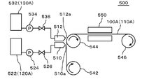
- FIG. 4 is a diagram for explaining an apparatus 500 for manufacturing a negative electrode sheet 100A.
- FIG. 5 is a diagram for explaining a process in which the negative electrode sheet 100A is manufactured by the apparatus 500 shown in FIG.
- the device 500 includes a first discharge head 510, a second discharge head 512, a first tank 522, a first pump 524, a first valve 526, a second tank 532, a second pump 534, and a second valve 536. It includes a first transfer roller 542, a second transfer roller 544, a third transfer roller 546, and a dryer 550.
- the first discharge head 510 and the second discharge head 512 have a discharge port 510a and a discharge port 512a, respectively.
- the first discharge head 510 and the second discharge head 512 may be configured by one discharge head.
- One discharge head may have at least a discharge port 510a and a discharge port 512a.
- the first transfer roller 542, the second transfer roller 544, and the third transfer roller 546 are in the direction of the arrows attached to the first transfer roller 542, the second transfer roller 544, and the third transfer roller 546 (clockwise). It is rotating around). Therefore, the negative electrode current collector sheet 110A is fed from the lower side to the upper side from the first transport roller 542 to the second transport roller 544, and is fed from the left side to the right side from the second transport roller 544 to the third transport roller 546. Has been done.
- This method (A) A step of applying a negative electrode active material slurry (hereinafter, also referred to as a first slurry 120A) containing at least a negative electrode active material and a binder on the first surface 112 of the negative electrode electrode sheet 100A. (B) A step of applying an insulating layer slurry (hereinafter, also referred to as a second slurry 130A) containing at least an insulating substance and a binder on the surface 122 of the negative electrode active material layer 120 (first slurry 120A). When, (C) The steps of simultaneously drying the first slurry 120A and the second slurry 130A applied in the above step (A) and the above step (B) are included in at least this order.
- a negative electrode active material slurry hereinafter, also referred to as a first slurry 120A
- an insulating layer slurry hereinafter, also referred to as a second slurry 130A
- the first slurry 120A wets and spreads along the first surface 112 of the negative electrode current collector sheet 110A and is applied to the first surface 112 of the negative electrode current collector sheet 110A (FIG. 5 (FIG. 5). a) See).
- the second slurry 130A wets and spreads along the surface 122 of the negative electrode active material layer 120 formed by the first slurry 120A applied in the step (A), and spreads wet and spreads along the surface 122 of the negative electrode active material layer 120. Is applied to the surface 122 of (see FIG. 5 (b)).
- a mixed layer 320 of the negative electrode active material layer 120 (first slurry 120A) and the insulating layer 300 (second slurry 130A) is located at the interface between the negative electrode active material layer 120 and the insulating layer 300. Is formed.
- the thickness of the mixed layer 320 is thinner than the thickness of the negative electrode active material layer 120.
- the first slurry 120A is housed in the first tank 522.
- the second slurry 130A is housed in the second tank 532.
- the first slurry 120A housed in the first tank 522 is supplied to the discharge head 510 via the first pump 524 and the first valve 526.
- the second slurry 130A housed in the second tank 532 is supplied to the discharge head 510 via the second pump 534 and the second valve 536.
- the first slurry 120A supplied to the discharge head 510 is discharged from the discharge port 510a of the first discharge head 510 toward the first surface 112 of the negative electrode current collector sheet 110A.
- the pressure of the first slurry 120A discharged to the first surface 112 of the negative electrode current collector sheet 110A is adjusted by, for example, the first pump 524.
- the flow rate of the first slurry 120A discharged to the first surface 112 of the negative electrode current collector sheet 110A is adjusted by, for example, the first valve 526.
- the second slurry 130A supplied to the discharge head 510 is discharged from the discharge port 512a of the second discharge head 512 toward the first surface 112 of the negative electrode current collector sheet 110A.
- the pressure of the second slurry 130A discharged to the first surface 112 of the negative electrode current collector sheet 110A is adjusted by, for example, the second pump 534.
- the flow rate of the second slurry 130A discharged to the first surface 112 of the negative electrode current collector sheet 110A is adjusted by, for example, the second valve 536.
- the first slurry 120A and the second slurry 130A are sequentially discharged from the discharge port 510a of the first discharge head 510 and the discharge port 512a of the second discharge head 512, respectively. Therefore, the second slurry 130A further wets and spreads along the upper surface 122 of the negative electrode active material layer 120 formed by the first slurry 120A that wets and spreads along the first surface 112.
- the first slurry 120A and the second slurry 130A are continuously applied in the direction in which the negative electrode current collector sheet 110A is conveyed. Therefore, the first slurry 120A and the second slurry 130A applied to the negative electrode current collector sheet 110A are continuously stretched along the direction in which the negative electrode current collector sheet 110A is conveyed.
- At least the discharge port 510a of the first discharge head 510 and the discharge port 512a of the second discharge head 512 are provided so as to be aligned in the direction in which the negative electrode current collector sheet 110A is conveyed.
- the first slurry 120A is discharged from the discharge port 510a of the first discharge head 510
- the second slurry 130A is discharged from the discharge port 512a of the second discharge head 512.
- the distance between the discharge port 510a of the first discharge head 510 and the discharge port 512a of the second discharge head 512 can be appropriately set.
- the first slurry 120A contains a material to be the negative electrode active material layer 120 and a solvent.
- the solvent contained in the first slurry 120A is, for example, water.
- the second slurry 130A contains a material to be the insulating layer 300 and a solvent.
- the solvent contained in the second slurry 130A is, for example, water.
- the solid content concentration of the first slurry 120A is 40% or more and 80% or less.
- the solid content concentration of the second slurry 130A is 20% or more and 80% or less.
- the negative electrode current collector sheet 110A is sent to the dryer 550.
- the first slurry 120A and the second slurry 130A are dried by the dryer 550.
- the first slurry 120A and the second slurry 130A are formed on the negative electrode active material layer 120 and the insulating layer 300, respectively, by drying the dryer 550.
- the negative electrode active material layer 120 (first slurry) is located at the interface between the negative electrode active material layer 120 formed by the first slurry 120A and the insulating layer 300 formed by the second slurry 130A.
- a mixed layer 320 of the insulating layer 300 (second slurry 130A) and the insulating layer 300 (120A) is formed.
- the thickness of the mixed layer 320 is thinner than that of the negative electrode active material layer 120.
- the thickness of the mixed layer 320 is evaluated by the following method.
- the direction from the surface 122 of the negative electrode active material layer 120 toward the current collector 110 is the Z direction.
- a scanning electron microscope (SEM) is used to analyze an SEM image obtained by photographing a cross section of the negative electrode electrode 100.
- element mapping is performed using an energy dispersive X-ray spectroscopy (EDX) method.
- EDX energy dispersive X-ray spectroscopy
- Z B be the average thickness of the negative electrode active material layer 120 in the Z direction. At this time, Z A / Z B is 11% or less.
- the maximum value Z A of Z-direction thickness is preferably at 35 ⁇ m or less, more preferably 25 ⁇ m or less.
- the negative electrode electrode 100 has an insulating material and a binder on the surface 122 of the negative electrode active material layer 120 formed on the first surface 112 of the sheet-shaped current collector 110. It has an insulating layer 300 including at least.
- the binder contained in the insulating layer 300 includes at least one selected from styrene-butadiene rubber and carboxymethyl cellulose and a salt thereof, and the negative electrode active material layer 120 contains at least one.
- the binder contained may be at least one selected from polyacrylic acid and salts thereof. This makes it possible to manufacture the negative electrode 100 in which the negative electrode active material layer 120 and the insulating layer 300 are not excessively mixed.
- the insulating layer 300 is applied after the negative electrode active material layer 120 is coated, dried, and pressed, a thin mixed layer is formed between the negative electrode active material layer 120 and the insulating layer 300. 320 is not formed. Therefore, the peel strength between the negative electrode active material layer 120 and the insulating layer 300 is low, and similarly, it cannot be said that the insulating function between the positive electrode and the negative electrode is sufficient.
- the insulating layer 300 cannot be uniformly applied due to the unevenness and wrinkles of the pressed surface to be coated, and the alliance cannot be obtained due to the gloss of the surface to be coated. Therefore, the negative electrode active material layer 120 may not be completely covered by the insulating layer 300, or the insulating layer 300 may be coated on a portion where the insulating layer 300 should not be coated.
- the solvents used for the slurry of the negative electrode active material layer 120 and the insulating layer 300 are not the same, the affinity Is low, so the mixed layer 320 is not formed.
- the negative electrode current collector sheet 110A is mounted on the negative electrode current collector sheet 110A.
- step (C) A step of simultaneously drying the slurry applied in the step (A) and the step (B), and Is included at least in this order, so that the above-mentioned problems of the sequential coating and drying method are solved, and when the insulating layer 300 is formed on the negative electrode active material layer 120, between the negative electrode active material layer 120 and the insulating layer 300. It is possible to improve the adhesion of the insulating layer 300 and prevent the insulating performance of the insulating layer 300 from deteriorating.
- the simultaneous drying method even if the solvent used for the slurry of the negative electrode active material layer 120 and the insulating layer 300 is the same, if the combination of the binder used for each slurry is not appropriate, the insulating layer slurry (second slurry) There was excessive penetration of 130A) into the negative electrode active material layer 120.
- the manufacturing method of the present embodiment by using the binder used for each slurry in an appropriate combination, it is possible to prevent the insulating layer slurry (second slurry 130A) from excessively permeating into the negative electrode active material layer 120. , It is possible to prevent the insulation performance of the insulating layer from deteriorating.
- the thickness of the mixed layer 320 of the negative electrode active material layer 120 and the insulating layer 300 formed at the interface between the negative electrode active material layer 120 and the insulating layer 300 is the thickness of the negative electrode active material layer 120. Thinner than thick.
- the active material is not exposed on the surface of the insulating layer 300, and the insulating function is impaired. There is no such thing. As a result, the insulating functions of the positive electrode and the negative electrode of the lithium ion secondary battery can be appropriately maintained.
- the maximum depth Z A at which the insulating material is detected in the negative electrode active material layer 120 is Z A / Z B , where Z B is the average thickness of the negative electrode active material layer in the Z direction. Is 11% or less, so that the diffusion of the insulating substance into the negative electrode active material layer 120 is not excessive.
- the particle size of the insulating substance is limited to 0.2 ⁇ m or more and 0.8 ⁇ m or less. This can prevent the problem that the insulating substance is not covered if the particle size is too small, and the problem that the number of particles is smaller than the film thickness and the insulating property is lowered if the particle size is too large. That is, it promotes a suitable coating, and since the particles are contained in an appropriate ratio with respect to the film thickness, it is possible to maintain an appropriate insulating property.
- the amount of the binder (binder) of the insulating layer 300 by limiting the amount of the binder (binder) of the insulating layer 300, it is possible to solve the problem that the adhesion deteriorates if the amount of the binder is too small. Further, when the amount of the binder is large, the gap in the insulating layer becomes small, the movement of the lithium salt between the positive and negative electrodes is hindered, and the problem that the resistance of the battery increases can be solved.
- the binder (binder) of the negative electrode active material layer 120 by limiting the amount of the binder (binder) of the negative electrode active material layer 120, a sufficient amount of the negative electrode active material is secured, and there is no excessive binder having high electrical resistance. The effect that a high-capacity and high-output electrode can be obtained can be obtained.
- the separator arranged between the positive electrode 200 and the negative electrode 100 becomes unnecessary.
- the lithium ion secondary battery can be made thinner, and a short circuit between the positive electrode and the negative electrode of the lithium ion secondary battery can be prevented.
- the negative electrode active material slurry (first slurry 120A) containing at least the negative electrode active material, the binder, and the solid electrolyte is applied.
- the solid electrolyte is, for example, Li 7 La 3 Zr 2 O 12 (LLZ).
- a high resistance layer slurry (second slurry 130A) containing at least a solid electrolyte and a binder is applied on the surface 122 of the negative electrode active material layer 120.
- the solid electrolyte is, for example, Li 7 La 3 Zr 2 O 12 (LLZ).
- the slurry applied in the step (A) and the step (B) is dried at the same time.
- the insulating substance contained in the insulating layer 300 is, for example, aluminum oxide (for example, ⁇ -alumina), silica, acrylic resin, magnesia, calcia, titania, zirconia, boehmite, and the like. And at least one selected from magnesium hydroxide.
- the high resistance layer is a solid electrolyte and does not necessarily have to contain the insulating substance contained in the above-mentioned insulating layer 300. That is, in the case of an all-solid-state battery, the high resistance layer (high resistance layer slurry) may contain at least a solid electrolyte.
- Table 1 shows the production conditions and evaluation results of the negative electrode 100 of Examples 1 to 11. Details of the sample production conditions will be described below.
- the negative electrode active material constituting the negative electrode active material layer 120 natural graphite coated with amorphous graphite manufactured by Hitachi Kasei Co., Ltd. was used.
- the negative electrode active material layer 120 contained a conductive auxiliary agent, and carbon black was used as the conductive auxiliary agent.
- carbon black C65 was set to 0.4% by weight based on the total weight of the solid material constituting the negative electrode active material layer 120.
- binder (binder) constituting the negative electrode active material layer 120 Aqua Charge manufactured by Sumitomo Seika Chemical Co., Ltd. was used as polyacrylic acid (PAA).
- any one of alumina, an acrylic resin (PolyMethylMethacrylate resin (PMMA)), and silica was used.
- alumina Alumina AKP-3000 manufactured by Sumitomo Chemical Co., Ltd. was used.
- acrylic resin (PMMA) a part number (grade) MX-80H3wT (average particle diameter 0.8 ⁇ m, degree of cross-linking: high) of the cross-linked acrylic monodisperse particle MX series manufactured by Soken Chemical Co., Ltd. was used.
- silica SFP-20M (0.3 ⁇ m) or SFP-30M (0.6 ⁇ m) of Super Fine Powder (submicron silica) manufactured by Denka Co., Ltd. was used.
- binder that constitutes the insulating layer 300 a mixture of sodium carboxymethyl cellulose (CMC-Na: Sodium Carboxymethyl Cellulose) and styrene butadiene rubber (SBR: Styrene-Butadiene Rubber) was used.
- CMC MAC-350HC of MAC series of Sunrose (registered trademark) manufactured by Nippon Paper Industries Co., Ltd. was used.
- SBR BM-451B manufactured by Nippon Zeon Corporation was used.
- the viscosity of each slurry was 8000 ⁇ 2000 mPa ⁇ s (conditions: B-type viscometer, 20 ° C., shear rate 2.04s-1). Simultaneous coating was performed using the two first discharge heads 510 and the second discharge head 512 of FIG. Simultaneous coating will be described later.
- the unit weight, the anode active material layer 120 is 11 mg / cm 2
- the insulating layer 300 was 2 mg / cm 2.
- some Examples and Comparative Examples prepared samples in which the basis weight of the insulating layer 300 was changed.
- the negative electrode 100 produced by the following method was evaluated. (1) Continuity confirmation by tester Samples of Examples 1 to 11 and Comparative Examples 1 to 14 were performed. The results are shown in Tables 1 and 2. (2) Photographs of the electrode surface were taken and the whiteness was measured. The samples of Example 1, Comparative Examples 1, 5 and 9 were taken. The results will be described later.
- the slurry applied in the following steps (A) and (B) was dried at the same time.
- the coating steps (A) and (B) are sequentially performed, and drying the two types of slurry at the same time is called simultaneous coating.
- the sequential coating after the following step (A), the slurry applied in the step (A) was dried, and then the following step (B) was performed to dry the slurry applied in the step (B).
- B) Insulation containing at least an insulating material and a binder on the surface of the negative electrode active material layer Process of applying layer slurry
- Continuity confirmation by tester was a digital multimeter (CDM-2000) manufactured by Custom Co., Ltd. The resistance range was measured at 30 M ⁇ .
- the negative electrode electrode sheet 100A includes a copper foil (current collector sheet), a negative electrode active material layer 120, and an insulating layer 300.
- the continuity confirmation method was set to "insulation” if the measurement limit (open range) was applied by applying the tip of the test lead of the tester from the front and back surfaces of the 10 cm square sample. Continuity was confirmed for 10 samples, and the ratio of the number of insulated samples (the number of samples for which continuity was not obtained) was calculated. If all 10 are insulated, it is 100%.
- the insulation rate was 100% in all of Examples 1 to 11. In other words, in any of Examples 1 to 11, it is shown that good insulation was obtained in all 10 samples.
- the binder contained in the insulating layer 300 includes at least one selected from styrene-butadiene rubber and carboxymethyl cellulose and a salt thereof, and the negative electrode active material layer 120.
- the binder (binder) contained in was at least one selected from polyacrylic acid and salts thereof.
- the binder contained in the insulating layer 300 is a mixture of CMC and SBR, and the binder contained in the negative electrode active material layer 120 is a binder. PAA was used.
- the D50 particle size in which the cumulative volume in the particle size distribution of the insulating substance constituting the insulating layer 300 is 50% is in the range of 0.2 ⁇ m or more and 0.8 ⁇ m or less.
- Example 10 is 0.3 ⁇ m (small)
- Example 11 is 0.6 ⁇ m (large)
- Examples 1 to 8 are 0.7 ⁇ m (large)
- Example 9 is 0.8 ⁇ m (large). I used the one. No effect of the D50 particle size of the insulating material on the insulation rate was observed.
- the weight of SBR contained in the insulating layer 300 was set to 3% by weight or more and 6% by weight or less in the total weight of the solid materials constituting the insulating layer 300.
- Examples 1 to 3, 6 to 8 and 11 were 3% by weight
- Examples 4 to 5 and 10 were 4% by weight
- Example 9 was 6% by weight.
- the total content of CMC and SBR of the binder of the insulating layer 300 is 7% by weight in Examples 1 to 2, 6 to 8 and 10, 6% by weight in Examples 3 and 11, and 9% by weight in Example 4.
- Example 5 10% by weight was used, and in Example 9, 12% by weight was used. No effect on the insulation rate was observed due to the total contents of CMC and SBR of the binder of the insulating layer 300.
- Example 1 In each of Examples 1 to 11, of the total weight of the solid material constituting the negative electrode active material layer 120, the polyacrylic acid contained in the negative electrode active material layer 120 and the binder of the salt thereof, the polyacrylic acid. And the total weight of the salt was 3% by weight or more and 6% by weight or less. Specifically, the weight of the PAA of the binder was set to 3% by weight in Examples 1 to 6 and 9 to 11, 4% by weight in Example 7, and 6% by weight in Example 8. This is included in the range of 3% by weight or more and 6% by weight or less. No effect on the insulation rate was observed due to the PAA content of the binder of the negative electrode active material layer 120.
- the insulating substance constituting the insulating layer 300 is at least one selected from alumina, silica, acrylic resin, magnesia, calcia, titania, zirconia, boehmite, and magnesium hydroxide. It was included. Specifically, Alumina was used in Examples 1 to 8, acrylic resin was used in Example 9, and silica was used in Examples 10 to 11.
- Example 2 was a 2.6 mg / cm 2 larger than the 2.0 mg / cm 2 of basis weight of the insulating layer 300 in Example 1. No effect on the insulation rate was observed due to the basis weight of the insulating layer 300.
- silica was added to the negative electrode active material, and the PAA content of the binder was changed.
- silica was 2.9% by weight (small)
- PAA was 3% by weight
- silica was 9.6% by weight (small) in the total weight of the solid material constituting the negative electrode active material layer 120.
- PAA was 4% by weight
- silica was 37.4% by weight (large)
- PAA was 6% by weight in Example 8.
- the content of PAA was 3% by weight or more and 6% by weight or less.
- the addition of silica to the negative electrode active material did not affect the insulation rate.
- Table 2 shows the production conditions and evaluation results of the negative electrode 100 of Comparative Examples 1 to 14.
- the binder contained in the insulating layer 300 did not contain at least one selected from styrene-butadiene rubber and carboxymethyl cellulose and a salt thereof, and PAA was used. PAA was used as the binder contained in the negative electrode active material layer 120.
- the basis weight of the insulating layer 300 was 2.6 mg / cm 2 , which was larger than that of Comparative Example 1.
- the mixing ratio of PAA of the binder (binder) contained in the insulating layer 300 was made larger than that of Comparative Example 1.
- Comparative Example 4 silica was added to the graphite of Example 1 as the negative electrode active material, and the weight of the PAA of the binder contained in the negative electrode active material layer 120 out of the total weight of the solid materials constituting the negative electrode active material layer 120. was 4% by weight, which was higher than that of Comparative Example 1.
- Comparative Examples 1 to 4 show that insulation was obtained in 2 out of 10 samples, but good insulation was not obtained in 8 of them.
- the binder contained in the insulating layer 300 does not contain at least one selected from styrene-butadiene rubber and carboxymethyl cellulose and a salt thereof, and has good insulating properties in Comparative Examples 1 to 4. Was not obtained.
- the negative electrode active material Even if the amount of the insulating layer 300 is increased (Comparative Example 2) or the mixing ratio of PAA of the binder (binder) contained in the insulating layer 300 is increased (Comparative Example 3), the negative electrode active material. Even if silica was added to (Comparative Example 4) or the mixing ratio of PAA in the binder of the negative electrode active material layer 120 was increased (Comparative Example 4), the insulating property was 20% and was not affected by these conditions. ..
- Comparative Examples 5 to 8 CMC and SBR, which are not at least one selected from polyacrylic acid and salts thereof, were used as the binder contained in the negative electrode active material layer 120.
- the basis weight of the insulating layer 300 was 2.6 mg / cm 2 , which was larger than that of Comparative Example 5.
- the mixing ratio of CMC and SBR of the binder of the negative electrode active material layer 120 was made larger than that of Comparative Example 5.
- the total weight of the binder CMC and SBR contained in the negative electrode active material layer 120 was 4% by weight, which was larger than that of Comparative Example 5 among the total weight of the solid material constituting the negative electrode active material layer 120.
- Comparative Example 8 silica is added to the graphite of Comparative Example 5 as the negative electrode active material, and the weight of the PAA of the binder contained in the negative electrode active material layer 120 out of the total weight of the solid material constituting the negative electrode active material layer 120. was 4% by weight, which was higher than that of Comparative Example 5.
- Comparative Examples 5 to 8 show that good insulation was not obtained for all 10 samples.
- the binder contained in the negative electrode active material layer is not at least one selected from polyacrylic acid and a salt thereof, and the binder contained in the insulating layer 300 is styrene.
- Comparative Examples 5 to 8 containing at least one selected from butadiene rubber and carboxymethyl cellulose and a salt thereof good insulating properties were not obtained.
- Comparative Examples 9 to 11 CMC and SBR were used for the binders of both the negative electrode active material layer 120 and the insulating layer 300.
- the basis weight of the insulating layer 300 was 2.6 mg / cm 2 , which was larger than that of Comparative Example 9.
- the mixing ratio of CMC and SBR of the binder of the negative electrode active material layer 120 was made larger than that of Comparative Example 9.
- Comparative Examples 9 to 11 show that good insulation was not obtained for all 10 samples.
- the binder contained in the negative electrode active material layer 120 did not have good insulating properties in Comparative Examples 9 to 11, which are not at least one selected from polyacrylic acid and salts thereof.
- the insulating property is 0%. , Was not affected by these conditions.
- the insulating substance constituting the insulating layer 300 was an acrylic resin.
- both the binder of the negative electrode active material layer 120 and the insulating layer 300 are PAA
- Comparative Example 13 the binder of the negative electrode active material layer 120 is CMC and SBR
- the binder of the insulating layer 300 is PAA
- Comparative Example 14 is.
- the negative electrode active material layer 120 and the insulating layer 300 binder were both CMC and SBR.
- the insulation rate was 10%, and the insulation rate of Comparative Examples 13 and 14 was 0%. That is, even if an acrylic resin is used for the insulating layer 300, the binder contained in the negative electrode active material layer is not at least one selected from polyacrylic acid and a salt thereof, and is contained in the insulating layer 300. In Comparative Examples 5 to 8 in which the binder (binder) contained at least one selected from styrene-butadiene rubber, carboxymethyl cellulose and a salt thereof, good insulating properties could not be obtained.
- the whiteness of the negative electrode active material layer 120 alone is 11.7, and the whiteness of the insulating layer 300 alone is 79.7. That is, in Comparative Example 5, it can be seen that the insulating layer 300 has substantially penetrated into the negative electrode active material layer 120 and has substantially the same whiteness as in the case of only the negative electrode active material layer 120. In Comparative Example 5, the insulation rate is also 0%.
- Comparative Example 1 and Comparative Example 9 it can be seen that a certain degree of the insulating layer 300 permeates the negative electrode active material layer 120, and the value is lower than the whiteness in the case of only the insulating layer 300. In Comparative Example 1 and Comparative Example 9, the insulation rate is as low as 0 to 20%.
- Example 1 the whiteness was slightly lower than that of the case where only the insulating layer 300 was used, and the insulation rate was 100%. That is, it can be seen that the insulating layer 300 permeates the negative electrode active material layer 120 by a certain amount while maintaining the insulating property.
- FIGS. 6 and 7 show the results of cross-sections of the samples of Example 1, Comparative Examples 1, 5, and 9.
- the SEM image and the element mapping image using the EDX method are arranged in the order of left and right.
- the upper image of FIG. 6 is the sample of Example 1
- the lower image of FIG. 6 is the sample of Comparative Example 9
- the upper image of FIG. 7 is the sample of Comparative Example 1
- the lower image of FIG. 7 is the sample of Comparative Example 1.
- the results of the sample of Comparative Example 5 are shown.
- the uppermost layer is the insulating layer 300
- the lowermost layer is the negative electrode current collector 110
- the center is the negative electrode active material layer 120.
- the negative electrode of the second slurry 130A constituting the insulating layer 300 at the interface between the insulating layer 300 and the negative electrode active material layer 120 of the sample of Example 1 It can be seen that the penetration into the active material layer 120 is the least.
- a mixed layer 320 of the negative electrode active material layer 120 and the insulating layer 300 which is thinner than the thickness of the negative electrode active material layer 120, is formed. ..
- Z A / Z B was 6.1%, which was 11% or less.
- Z A was 6.3 ⁇ m.
- the insulation rate of the sample of Example 1 was 100%.
- the second slurry 130A constituting the insulating layer 300 It can be seen that the penetration into the negative electrode active material layer 120 is the largest.
- the above-mentioned Z A / Z B was 79%, which was 11% or more.
- the insulation rate of the sample of Comparative Example 9 was 0%.
- the sample of Comparative Example 1 (upper side of FIG. 7) has the insulating layer 300 and the negative electrode active material layer more than the sample of Comparative Example 5 (lower side of FIG. 7). It can be seen that at the interface between 120, the penetration of the second slurry 130A constituting the insulating layer 300 into the negative electrode active material layer 120 is small.
- the above-mentioned Z A / Z B of the samples of Comparative Example 1 and Comparative Example 5 were 44% and 36%, respectively, and both were 11% or more.
- the insulation rate of the sample of Comparative Example 1 is 20%, which is higher than the insulation rate of the sample of Comparative Example 5 of 0%.
- a negative electrode for a lithium ion secondary battery in which a negative electrode active material layer containing at least a negative electrode active material and a binder is formed.
- An insulating layer containing at least an insulating substance and a binder is further provided on the surface of the negative electrode active material layer.
- the binder contained in the insulating layer contains at least styrene-butadiene rubber and at least one selected from carboxymethyl cellulose and a salt thereof.
- the binder contained in the negative electrode active material layer is a negative electrode for a lithium ion secondary battery, which is at least one selected from polyacrylic acid and a salt thereof. 2.
- the negative active not detected from material, said insulation and Z a maximum value of Z direction elements to be detected is detected from the material, the average thickness of the Z direction of the negative electrode active material layer when was the Z B, Z a / Z B is less than 11%, 1. 1. Or 2. Negative electrode for lithium ion secondary battery according to. 4. Maximum value Z A of the thickness of the Z-direction is 35 ⁇ m or less, 3. 3. Negative electrode for lithium ion secondary battery according to. 5. The D50 particle size at which the cumulative volume in the particle size distribution of the insulating substance is 50% is 0.2 ⁇ m or more and 0.8 ⁇ m or less. 1. 1. From 4. The negative electrode for the lithium ion secondary battery according to any one of the above. 6.
- the weight of the styrene-butadiene rubber contained in the insulating layer is 3% by weight or more and 6% by weight or less. 1. 1. From 5.
- the total weight of polyacrylic acid and its salt among the binders of polyacrylic acid and its salt contained in the negative electrode active material layer is 3 weight. % Or more and 6% by weight or less, 1. 1. From 6.
- the insulating material comprises at least one selected from alumina, silica, acrylic resin, magnesia, calcia, titania, zirconia, boehmite, and magnesium hydroxide.
- alumina silica
- acrylic resin magnesia
- calcia calcia
- titania zirconia
- boehmite magnesium hydroxide.
- a lithium ion secondary battery including a positive electrode having a positive electrode active material layer formed on a current collector, a negative electrode, and an electrolyte, wherein the negative electrode is 1. From 8. The negative electrode according to any one of the above. Lithium-ion secondary battery. 10. The insulating layer is formed on at least the entire surface of the negative electrode active material layer of the negative electrode facing the region where the active material layer of the positive electrode is formed. 9. Lithium ion secondary battery described in. 11. A separator different from the insulating layer formed on the negative electrode active material layer of the negative electrode is not arranged between the positive electrode and the negative electrode. 9. Or 10. Lithium ion secondary battery described in.
- a step of applying a negative electrode active material slurry containing at least a negative electrode active material and a binder and
- B A step of applying an insulating layer slurry containing at least an insulating substance and a binder on the surface of the negative electrode active material slurry.
- C A step of simultaneously drying the slurry applied in the step (A) and the step (B), and A method for manufacturing a negative electrode for a lithium ion secondary battery, which comprises at least in this order.
- the binder contained in the insulating layer slurry contains at least styrene-butadiene rubber and at least one selected from carboxymethyl cellulose and a salt thereof.
- a method for manufacturing a negative electrode for a lithium ion secondary battery wherein the binder contained in the negative electrode active material slurry is at least one selected from polyacrylic acid and a salt thereof. 13.
- the negative electrode active material slurry containing at least the negative electrode active material and the binder, and the insulating layer slurry containing at least the insulating material and the binder are continuous in the direction in which the current collector sheet is continuously conveyed.
- a method for manufacturing a negative electrode sheet for a lithium ion secondary battery which is specifically applied. 14.
- the negative electrode active material slurry is discharged from the first discharge port, and the insulating layer is used. Discharge the slurry from the second discharge port.
- the solid content concentration of the negative electrode active material slurry is 40% or more and 80% or less, and the solid content concentration of the insulating layer slurry is 20% or more and 80% or less. 13.
- the viscosity of the negative electrode active material slurry at a shear rate of 2.04s-1 at 20 ° C. by a B-type viscometer is 6 Pa ⁇ S or more and 10 Pa ⁇ S or less, and at 20 ° C. by a B-type viscometer of the insulating layer slurry.
- the viscosity at a shear rate of 2.04s-1 is 6 Pa ⁇ S or more and 10 Pa ⁇ S or less.
- the D50 particle diameter at which the cumulative volume in the particle size distribution of the insulating substance contained in the insulating layer slurry is 50% is 0.2 ⁇ m or more and 0.8 ⁇ m or less. 13.
- the polyacrylic acid and the total weight of the salt is 3% by weight or more and 6% by weight or less. 13. From 18. The method for manufacturing a negative electrode sheet for a lithium ion secondary battery according to any one of the above. 20.
- the insulating substance contains at least one selected from alumina, silica, acrylic resin, magnesia, calcia, titania, zirconia, boehmite, and magnesium hydroxide. 13. From 19. The method for manufacturing a negative electrode sheet for a lithium ion secondary battery according to any one of the above.
- a negative electrode for a lithium ion secondary battery in which a negative electrode active material layer containing at least a negative electrode active material and a binder is formed.
- a high resistance layer containing at least a solid electrolyte and a binder is further provided on the surface of the negative electrode active material layer.
- the binder contained in the high resistance layer contains at least styrene-butadiene rubber and at least one selected from carboxymethyl cellulose and a salt thereof.
- the binder contained in the negative electrode active material layer is a negative electrode for an all-solid-state lithium ion secondary battery, which is at least one selected from polyacrylic acid and a salt thereof. 22.
- Negative electrode for all-solid-state lithium-ion secondary battery according to. 23. When elemental mapping is performed using the EDX method in the cross-sectional SEM image of the cross section of the negative electrode, the direction of the negative electrode active material layer from the surface of the negative electrode active material layer on the side not in contact with the current collector toward the current collector side.
- the maximum value in the Z direction in which elements that are not detected in the negative electrode active material and are detected in the solid electrolyte are detected is Z A
- the average thickness of the negative electrode active material layer in the Z direction is defined as Z A.
- Z B Z A / Z B is 11% or less.
- Negative electrode for all-solid-state lithium-ion secondary battery according to. 24 Maximum value Z A of the thickness of the Z-direction is 35 ⁇ m or less, 23.
- the D50 particle size at which the cumulative volume in the particle size distribution of the solid electrolyte is 50% is 0.2 ⁇ m or more and 0.8 ⁇ m or less. 21. From 24.
- the weight of the styrene-butadiene rubber contained in the high resistance layer is 3% by weight or more and 6% by weight or less. 21. From 25.
- the total weight of polyacrylic acid and its salt among the binders of polyacrylic acid and its salt contained in the negative electrode active material layer is 3 weight. % Or more and 6% by weight or less, 21. From 26.
- An all-solid-state lithium-ion secondary battery including a positive electrode having a positive electrode active material layer formed on a current collector, a negative electrode, and a solid electrolyte, wherein the negative electrode is 21. From 27. The negative electrode according to any one of the above. All-solid-state lithium-ion secondary battery.
- a step of applying a negative electrode active material slurry containing at least a negative electrode active material and a binder A step of applying a high resistance layer slurry containing at least a solid electrolyte and a binder on the surface of the negative electrode active material slurry.
- C A step of simultaneously drying the slurry applied in the step (A) and the step (B), and A method for manufacturing a negative electrode for an all-solid-state lithium-ion secondary battery, which comprises at least in this order.
- the binder contained in the high resistance layer slurry contains at least styrene-butadiene rubber and at least one selected from carboxymethyl cellulose and a salt thereof.
- a method for manufacturing a negative electrode for an all-solid-state lithium ion secondary battery wherein the binder contained in the negative electrode active material slurry is at least one selected from polyacrylic acid and a salt thereof.
- a method for manufacturing a negative electrode sheet for an all-solid-state lithium-ion secondary battery for manufacturing a negative electrode for an all-solid-state lithium-ion secondary battery by the manufacturing method described in 1.
- the negative electrode active material slurry containing at least the negative electrode active material and the binder, and the high resistance layer slurry containing at least the solid electrolyte and the binder are continuous in the direction in which the collector sheet is continuously conveyed.
- a method for manufacturing a negative electrode sheet for an all-solid-state lithium-ion secondary battery are continuous in the direction in which the collector sheet is continuously conveyed.
- Lithium ion secondary battery 12 Laminated body 150 1st lead 250 2nd lead 400 Exterior material 100 Negative electrode 100A Negative electrode electrode sheet 110 Negative electrode current collector 110A Negative electrode current collector sheet 112 1st surface 114 2nd surface 120 Negative electrode active material Layer 122 Surface 200 Positive Electrode 210 Positive Electrode Collector 212 Third Surface 214 Fourth Surface 220 Positive Active Material Layer 300 Insulation Layer 312 Fifth Surface 314 Sixth Surface 320 Mixed Layer 120A First Slurry 130A Second Slurry 500 Device 510 1 Discharge head 510a Discharge port 512 2nd discharge head 512a Discharge port 522 1st tank 524 1st pump 526 1st valve 532 2nd tank 534 2nd pump 536 2nd valve 542 1st transfer roller 544 2nd transfer roller 546 3 Conveying roller 550 dryer
Abstract
リチウムイオン二次電池用の負極電極(100)は、集電体(110)上に、負極活物質と、結着材と、を少なくとも含む負極活物質層(120)が形成されたリチウムイオン二次電池用の負極電極(100)であって、負極活物質層(120)の表面上に、絶縁性物質と、結着材と、を少なくとも含む絶縁層(300)をさらに有し、絶縁層(300)に含まれる結着材は、スチレンブタジエンゴムと、カルボキシメチルセルロースおよびその塩から選ばれる少なくとも1種と、を少なくとも含み、負極活物質層(120)に含まれる結着材は、ポリアクリル酸およびその塩から選ばれる少なくとも1種である。
Description
本発明は、負極電極、リチウムイオン二次電池、リチウムイオン二次電池用負極電極の製造方法、および、リチウムイオン二次電池用負極電極シートの製造方法に関する。
リチウムイオン二次電池は、負極電極と、正極電極と、負極電極と正極電極の間に介在するセパレータとを含んでいる。特許文献1には、負極活物質およびバインダを含有する負極合剤層を有する負極、正極、セパレータおよび非水電解液が外装体内に収容された非水二次電池が開示されている。この特許文献1には、セパレータには多孔質膜を使用し、その表面に、耐熱性の無機フィラーを含有する耐熱性の多孔質層を形成することが記載されている。
特許文献1に記載されている構造では、電極とセパレータ上の耐熱層が一体化していないため、発熱時に基材が収縮すると、基材側に接着した耐熱層も付随して動くため、正極と負極の絶縁機能として十分とは言えなかった。
特許文献2には、セパレータを含まないリチウムイオン二次電池の製造方法が記載されている。特許文献1に記載の製造方法では、電極活物質層と、絶縁層とをこの順に配置された積層構造を有し、電極集電体の少なくとも一方の面に活物質層材料を塗布して第1の塗膜を形成し、第1の塗膜の上に絶縁層材料を塗膜して第2の塗膜を形成した後、第1の塗膜と第2の塗膜を同時に乾燥している。
第1の塗膜の上に絶縁層材料を塗膜して第2の塗膜を形成した後、第1の塗膜と第2の塗膜を同時に乾燥する同時乾燥方式の場合、活物質層材料の中に絶縁層材料が浸透し、その結果、活物質層と絶縁層との間に混合層が形成される。この混合層が形成されると、活物質層と絶縁層の密着強度は高くなる。しかし、活物質材料の中に絶縁材料が浸透しすぎると、絶縁層の表面に活物質層が露出する可能性が出てくる。この場合、絶縁層の絶縁性能は低下してしまう。
本発明は上記事情に鑑みてなされたものであり、その目的とするところは、活物質層の上に絶縁層(高抵抗層)を形成する場合において、活物質層と絶縁層(高抵抗層)の間の密着性を高めつつ、絶縁層(高抵抗層)の絶縁性能が低下しないようにすることにある。
本発明の各側面では、上述した課題を解決するために、それぞれ以下の構成を採用する。
第一の側面は、リチウムイオン二次電池用の負極電極に関する。
第一の側面に係る第1のリチウムイオン二次電池用の負極電極は、
集電体上に、
負極活物質と、結着材と、を少なくとも含む負極活物質層が形成されたリチウムイオン二次電池用の負極電極であって、
前記負極活物質層の表面上に、絶縁性物質と、結着材と、を少なくとも含む絶縁層をさらに有し、
前記絶縁層に含まれる結着材は、スチレンブタジエンゴムと、カルボキシメチルセルロースおよびその塩から選ばれる少なくとも1種と、を少なくとも含み、
前記負極活物質層に含まれる結着材は、ポリアクリル酸およびその塩から選ばれる少なくとも1種である。
第一の側面に係る第1のリチウムイオン二次電池用の負極電極は、
集電体上に、
負極活物質と、結着材と、を少なくとも含む負極活物質層が形成されたリチウムイオン二次電池用の負極電極であって、
前記負極活物質層の表面上に、絶縁性物質と、結着材と、を少なくとも含む絶縁層をさらに有し、
前記絶縁層に含まれる結着材は、スチレンブタジエンゴムと、カルボキシメチルセルロースおよびその塩から選ばれる少なくとも1種と、を少なくとも含み、
前記負極活物質層に含まれる結着材は、ポリアクリル酸およびその塩から選ばれる少なくとも1種である。
第一の側面に係る第2のリチウムイオン二次電池用の負極電極は、
全固体リチウムイオン二次電池用の負極電極であって、
集電体上に、
負極活物質と、結着材と、を少なくとも含む負極活物質層が形成されたリチウムイオン二次電池用の負極電極であって、
前記負極活物質層の表面上に、固体電解質と、結着材と、を少なくとも含む高抵抗層をさらに有し、
前記高抵抗層に含まれる結着材は、スチレンブタジエンゴムと、カルボキシメチルセルロースおよびその塩から選ばれる少なくとも1種と、を少なくとも含み、
前記負極活物質層に含まれる結着材は、ポリアクリル酸およびその塩から選ばれる少なくとも1種である。
全固体リチウムイオン二次電池用の負極電極であって、
集電体上に、
負極活物質と、結着材と、を少なくとも含む負極活物質層が形成されたリチウムイオン二次電池用の負極電極であって、
前記負極活物質層の表面上に、固体電解質と、結着材と、を少なくとも含む高抵抗層をさらに有し、
前記高抵抗層に含まれる結着材は、スチレンブタジエンゴムと、カルボキシメチルセルロースおよびその塩から選ばれる少なくとも1種と、を少なくとも含み、
前記負極活物質層に含まれる結着材は、ポリアクリル酸およびその塩から選ばれる少なくとも1種である。
第二の側面は、リチウムイオン二次電池に関する。
第二の側面に係る第1のリチウムイオン二次電池は、
集電体上に正極活物質層の形成された正極電極と、負極電極と、電解質とを備えるリチウムイオン二次電池であって、
前記負極電極は、上記第一の側面に係るリチウムイオン二次電池用の負極電極である。
第二の側面に係る第1のリチウムイオン二次電池は、
集電体上に正極活物質層の形成された正極電極と、負極電極と、電解質とを備えるリチウムイオン二次電池であって、
前記負極電極は、上記第一の側面に係るリチウムイオン二次電池用の負極電極である。
第二の側面に係る第2のリチウムイオン二次電池は、
集電体上に正極活物質層の形成された正極電極と、負極電極と、固体電解質とを備える全固体リチウムイオン二次電池であって、前記負極電極は、上記第一の側面に係る全固体リチウムイオン二次電池用の負極電極である。
集電体上に正極活物質層の形成された正極電極と、負極電極と、固体電解質とを備える全固体リチウムイオン二次電池であって、前記負極電極は、上記第一の側面に係る全固体リチウムイオン二次電池用の負極電極である。
第三の側面は、リチウムイオン二次電池用負極電極の製造方法に関する。
第三の側面に係る第1のリチウムイオン二次電池用負極電極の製造方法は、
シート状の集電体上に、
(A)負極活物質と、結着材と、を少なくとも含む負極活物質スラリを塗布する工程と、
(B)前記負極活物質スラリの表面上に、絶縁性物質と、結着材と、を少なくとも含む絶縁層スラリを塗布する工程と、
(C)前記工程(A)および前記工程(B)で塗布されたスラリを同時に乾燥する工程と、
を少なくともこの順番で含むリチウムイオン二次電池用負極電極の製造方法であって、
前記絶縁層スラリに含まれる結着材は、スチレンブタジエンゴムと、カルボキシメチルセルロースおよびその塩から選ばれる少なくとも1種、とを少なくとも含み、
前記負極活物質スラリに含まれる結着材は、ポリアクリル酸およびその塩から選ばれる少なくとも1種である。
第三の側面に係る第2のリチウムイオン二次電池用負極電極の製造方法は、
全固体リチウムイオン二次電池用の負極電極の製造方法であって、
シート状の集電体上に、
(A)負極活物質と、結着材と、を少なくとも含む負極活物質スラリを塗布する工程と、
(B)前記負極活物質スラリの表面上に、固体電解質と、結着材と、を少なくとも含む高抵抗層スラリを塗布する工程と、
(C)前記工程(A)および前記工程(B)で塗布されたスラリを同時に乾燥する工程と、
を少なくともこの順番で含む全固体リチウムイオン二次電池用負極電極の製造方法であって、
前記高抵抗層スラリに含まれる結着材は、スチレンブタジエンゴムと、カルボキシメチルセルロースおよびその塩から選ばれる少なくとも1種、とを少なくとも含み、
前記負極活物質スラリに含まれる結着材は、ポリアクリル酸およびその塩から選ばれる少なくとも1種である。
第四の側面は、リチウムイオン二次電池用負極電極シートの製造方法に関する。
第四の側面に係る第1のリチウムイオン二次電池用負極電極シートの製造方法は、
第三の側面に係る製造方法によりリチウムイオン二次電池用負極電極を製造するためのリチウムイオン二次電池用負極電極シートの製造方法であって、
負極活物質と、結着材と、を少なくとも含む負極活物質スラリと、絶縁性物質と、結着材と、を少なくとも含む絶縁層スラリとは、集電体シートが連続搬送される方向に連続的に塗布される工程を含む。
第四の側面に係る第1のリチウムイオン二次電池用負極電極シートの製造方法は、
第三の側面に係る製造方法によりリチウムイオン二次電池用負極電極を製造するためのリチウムイオン二次電池用負極電極シートの製造方法であって、
負極活物質と、結着材と、を少なくとも含む負極活物質スラリと、絶縁性物質と、結着材と、を少なくとも含む絶縁層スラリとは、集電体シートが連続搬送される方向に連続的に塗布される工程を含む。
第四の側面に係る第2のリチウムイオン二次電池用負極電極シートの製造方法は、
第三の側面に係る製造方法により全固体リチウムイオン二次電池用負極電極を製造するための全固体リチウムイオン二次電池用負極電極シートの製造方法であって、
負極活物質と、結着材と、を少なくとも含む負極活物質スラリと、固体電解質と、結着材と、を少なくとも含む高抵抗層スラリとは、集電体シートが連続搬送される方向に連続的に塗布される工程を含む。
第三の側面に係る製造方法により全固体リチウムイオン二次電池用負極電極を製造するための全固体リチウムイオン二次電池用負極電極シートの製造方法であって、
負極活物質と、結着材と、を少なくとも含む負極活物質スラリと、固体電解質と、結着材と、を少なくとも含む高抵抗層スラリとは、集電体シートが連続搬送される方向に連続的に塗布される工程を含む。
なお、以上の構成要素の任意の組合せ、本発明の表現を方法、装置、システム、記録媒体、コンピュータプログラムなどの間で変換したものもまた、本発明の態様として有効である。
また、本発明の各種の構成要素は、必ずしも個々に独立した存在である必要はなく、複数の構成要素が一個の部材として形成されていること、一つの構成要素が複数の部材で形成されていること、ある構成要素が他の構成要素の一部であること、ある構成要素の一部と他の構成要素の一部とが重複していること、等でもよい。
また、本発明の方法には複数の手順を順番に記載してあるが、その記載の順番は複数の手順を実行する順番を限定するものではない。このため、本発明の方法を実施するときには、その複数の手順の順番は内容的に支障のない範囲で変更することができる。
さらに、本発明の方法の複数の手順は個々に相違するタイミングで実行されることに限定されない。このため、ある手順の実行中に他の手順が発生すること、ある手順の実行タイミングと他の手順の実行タイミングとの一部ないし全部が重複していること、等でもよい。
本発明の上述した態様によれば、リチウムイオン二次電池の正極と負極の絶縁性能に優れた絶縁層または高抵抗層を提供することができる。
以下、本発明の実施の形態について、図面を用いて説明する。尚、すべての図面において、同様な構成要素には同様の符号を付し、適宜説明を省略する。
本明細書において、「第1」、「第2」、「第3」等の序数詞は、特に断りのない限り、同様の名称が付された構成を単に区別するために付されたものであり、構成の特定の特徴(例えば、順番または重要度)を意味するものではない。
図1は、実施形態に係るリチウムイオン二次電池10の上面図である。図2は、図1から第1リード150、第2リード250および外装材400を取り除いた図である。言い換えると、図2は、積層体12の上面図である。図3は、図2のA-A´断面図である。
図1から図3において、第1方向Xは、リチウムイオン二次電池10(積層体12)の長さ方向を示している。第1方向Xの負方向(第1方向Xを示す矢印によって示される方向)は、第1リード150から第2リード250に向かう方向である。第1方向Xの負方向(第1方向Xを示す矢印によって示される方向の反対方向)は、第2リード250から第1リード150に向かう方向である。第2方向Yは、リチウムイオン二次電池10(積層体12)の幅方向を示している。第2方向Yの負方向(第2方向Yを示す矢印によって示される方向)は、リチウムイオン二次電池10を第1方向Xの正方向から見て、リチウムイオン二次電池10(積層体12)の左方向である。第2方向Yの正方向(第2方向Yを示す矢印によって示される方向の反対方向)は、リチウムイオン二次電池10を第1方向Xの正方向から見て、リチウムイオン二次電池10(積層体12)の右方向である。第3方向Zは、リチウムイオン二次電池10(積層体12)の厚さ(高さ)方向である。第3方向Zの負方向(第3方向Zを示す矢印によって示される方向)は、リチウムイオン二次電池10(積層体12)の上方向である。第3方向Zの正方向(第3方向Zを示す矢印によって示される方向の反対方向)は、リチウムイオン二次電池10(積層体12)の下方向である。
図3を用いて、本実施形態に係る負極電極100の概要を説明する。
負極電極100は、負極集電体110上に、負極活物質と、結着材と、を少なくとも含む負極活物質層120が形成される。さらに、負極活物質層120の表面上に、絶縁性物質と、結着材と、を少なくとも含む絶縁層300を有する。絶縁層300に含まれる結着材は、スチレンブタジエンゴムと、カルボキシメチルセルロースおよびその塩から選ばれる少なくとも1種と、を少なくとも含む。負極活物質層120に含まれる結着材は、ポリアクリル酸およびその塩から選ばれる少なくとも1種である。
負極電極100は、負極集電体110上に、負極活物質と、結着材と、を少なくとも含む負極活物質層120が形成される。さらに、負極活物質層120の表面上に、絶縁性物質と、結着材と、を少なくとも含む絶縁層300を有する。絶縁層300に含まれる結着材は、スチレンブタジエンゴムと、カルボキシメチルセルロースおよびその塩から選ばれる少なくとも1種と、を少なくとも含む。負極活物質層120に含まれる結着材は、ポリアクリル酸およびその塩から選ばれる少なくとも1種である。
図1および図2を用いて、リチウムイオン二次電池10について説明する。
リチウムイオン二次電池10は、積層体12、第1リード150、第2リード250および外装材400を備えている。
第1リード150は、負極電極100(例えば、図3)に電気的に接続されている。第1リード150は、例えば、銅若しくは銅合金またはそれらにニッケルメッキを施したもので形成させてもよい。
第2リード250は、正極電極200(例えば、図3)に電気的に接続されている。第2リード250は、例えば、アルミニウムまたはアルミニウム合金で形成させてもよい。
外装材400は、4辺を有する矩形形状を有している。本実施形態において、第2リード250は、外装材400のうち第1方向Xの正方向側に位置する辺に設けられており、第1リード150は、外装材400のうち第1方向Xの負方向側に位置する辺に設けられている。ただし、第2リード250および第1リード150は、外装材400の共通の辺(例えば、第1方向Xの負方向側または正方向側に位置する辺)に設けられていてもよい。
リチウムイオン二次電池10の各セルは、負極電極100と、正極電極200と、電解質(不図示)とを含んでいる。電解質の状態は、液体、ゲル、および固体のいずれかであってもよい。本実施形態では、リチウムイオン二次電池10の電解質の状態は液体であり、「電解液」として説明する。固体電解質を用いる場合の製造工程については後述する。
外装材400は、積層体12を電解液(不図示)とともに収容している。
外装材400は、積層体12を電解液(不図示)とともに収容している。
外装材400は、例えば、熱融着性樹脂層およびバリア層を含み、例えば、熱融着性樹脂層およびバリア層を含む積層フィルムにしてもよい。
熱融着性樹脂層を形成する樹脂材料は、例えば、ポリエチレン(PE)、ポリプロピレン、ナイロン、ポリエチレンテレフタレート(PET)等にしてもよい。熱融着性樹脂層の厚さは、例えば、20μm以上200μm以下である。
バリア層は、例えば、電解液の漏出または外部からの水分の侵入防止といったバリア性を有しており、例えば、ステンレス(SUS)箔、アルミニウム箔、アルミニウム合金箔、銅箔、チタン箔等の金属により形成されたバリア層にしてもよい。バリア層の厚さは、例えば、10μm以上100μm以下である。
積層フィルムの熱融着性樹脂層は、1層であってもよいし、または2層以上であってもよい。同様にして、積層フィルムのバリア層は、1層であってもよいし、または2層以上であってもよい。
電解液は、例えば、非水電解液である。この非水電解液は、リチウム塩およびリチウム塩を溶解する溶媒を含んでいてもよい。
リチウム塩は、例えば、LiClO4、LiBF6、LiPF6、LiCF3SO3、LiCF3CO2、LiAsF6、LiSbF6、LiB10Cl10、LiAlCl4、LiCl、LiBr、LiB(C2H5)4、CF3SO3Li、CH3SO3Li、LiC4F9SO3、Li(CF3SO2)2N、低級脂肪酸カルボン酸リチウム等にしてもよい。
リチウム塩を溶解する溶媒は、例えば、エチレンカーボネート(EC)、プロピレンカーボネート(PC)、ブチレンカーボネート(BC)、ジメチルカーボネート(DMC)、エチルメチルカーボネート(EMC)、ジエチルカーボネート(DEC)、メチルエチルカーボネート(MEC)、ビニレンカーボネート(VC)等のカーボネート類;γ-ブチロラクトン、γ-バレロラクトン等のラクトン類;トリメトキシメタン、1,2-ジメトキシエタン、ジエチルエーテル、テトラヒドロフラン、2-メチルテトラヒドロフラン等のエーテル類;ジメチルスルホキシド等のスルホキシド類;1,3-ジオキソラン、4-メチル-1,3-ジオキソラン等のオキソラン類;アセトニトリル、ニトロメタン、ホルムアミド、ジメチルホルムアミド等の含窒素溶媒;ギ酸メチル、酢酸メチル、酢酸エチル、酢酸ブチル、プロピオン酸メチル、プロピオン酸エチル等の有機酸エステル類;リン酸トリエステルやジグライム類;トリグライム類;スルホラン、メチルスルホラン等のスルホラン類;3-メチル-2-オキサゾリジノン等のオキサゾリジノン類;1,3-プロパンスルトン、1,4-ブタンスルトン、ナフタスルトン等のスルトン類等にしてもよい。これらの物質は、単独で使用されてもよいし、または組み合わせて使用されてもよい。
図3を用いて、積層体12について説明する。
積層体12は、絶縁層300を塗布した複数の負極電極100と複数の正極電極200とを有している。絶縁層300を塗布した各負極電極100および各正極電極200は、第3方向Zに交互に積層されている。各絶縁層300は、第3方向Zに隣り合う正極電極200と負極電極100との間に位置している。ただし、積層体12は、絶縁層300を塗布した1つのみの負極電極100、および1つのみの正極電極200を有していてもよい。
ただし、積層体12は、一般的なポリオレフィン系のフィルム状セパレータを組み合わせる構成も排除されない。この場合、積層体12は、負極電極100と正極電極200とをセパレータを介して「積層」した構造(一層でもよい)、負極電極100と正極電極200とを長尺のセパレータを介して重ねて巻き取って巻回状にした「巻回」構造、および負極電極100と正極電極200とを長尺のセパレータを介してつづら折りにした「つづら折り」構造の少なくともいずれかの構造をとることができる。さらに、積層体12は、「積層」構造の複数の積層体12を、さらに、長尺のセパレータで巻回した構造や、つづら折りにした構造であってもよい。
一例として、上記「つづら折り」構造では、セパレータは、絶縁層300を塗布した負極電極100または正極電極200の第1方向Xにおける外側において第1方向X沿って折り返しながら、隣り合うと負極電極100と正極電極200の間を通過するように、つづら折りに延伸していてもよい。
負極電極100の詳細を説明する。負極電極100は、負極集電体110、および負極活物質層120を有している。
負極電極100の負極集電体110は、第1面112および第2面114を有している。負極集電体110の第1面112は、負極集電体110の上面である。負極集電体110の第2面114は、負極集電体110の第1面112の反対側にあり、負極集電体110の下面である。
負極集電体110の第1面112上には、負極活物質層120が位置している。負極集電体110の第2面114上には、他の負極活物質層120が位置している。ただし、負極活物質層120は、負極集電体110の第1面112および第2面114のうちの一方上のみに位置していてもよい。
負極集電体110の第1方向Xの負方向側の端部は、第1リード150(図1)に接続されている。例えば、第3方向Zにおいて、負極集電体110の第1方向Xの負方向側の端部と第1リード150とがずれているとき、負極集電体110の第1方向Xの負方向側の端部は、第1リード150に向けて曲がっていてもよい。
負極集電体110は、例えば、銅、ステンレス鋼、ニッケル、チタンまたはこれらの合金で形成させてもよい。負極集電体110の形状は、例えば、箔、平板またはメッシュにしてもよい。負極集電体110の第3方向Zにおける厚さ(第3方向Z)は、例えば、1μm以上50μm以下である。
負極活物質層120は、負極活物質と、バインダ樹脂と、を含んでいる。負極活物質層120は、必要に応じて、導電助剤をさらに含んでいてもよい。
負極活物質としては、リチウムイオン二次電池10の負極電極100に使用可能な通常の負極活物質であれば特に限定されない。例えば、リチウムを吸蔵する黒鉛、非晶質炭素、ダイヤモンド状炭素、フラーレン、カーボンナノチューブ、カーボンナノホーン等の炭素材料;リチウム金属、リチウム合金等のリチウム系金属材料;Si、SiO2、SiOx(0<x≦2)、Si含有複合材料等のSi系材料;ポリアセン、ポリアセチレン、ポリピロール等の導電性ポリマー材料等が挙げられる。負極活物質は1種単独で使用してもよいし、2種以上を組み合わせて使用してもよい。
負極活物質層120は、負極活物質層120の総質量100質量部に対して、例えば、90質量部以上99質量部以下の負極活物質を含んでいる。
負極活物質の平均粒径は、充放電時の副反応を抑えて充放電効率の低下を抑える点から、1μm以上が好ましく、2μm以上がより好ましく、入出力特性や負極電極100の作製上の観点(負極電極100の表面の平滑性等)から、100μm以下が好ましく、50μm以下がより好ましい。ここで、平均粒径は、レーザ回折散乱法による粒度分布(体積基準)における積算値50%での粒子径(メジアン径:D50)を意味する。
負極活物質層120の密度は、例えば、1.2g/cm3以上2.0g/cm3以下である。
負極集電体110の両面(第1面112および第2面114)のうちの一方の面上の負極活物質層120の厚さ(第3方向Z)は、適宜決定することができる。当該厚さは、例えば、80μm以下である。
負極集電体110の両面(第1面112および第2面114)上の負極活物質層120の厚さ(第3方向Z)の合計は、適宜決定することができる。当該厚さは、例えば、160μm以下である。
負極活物質層120に含まれるバインダ樹脂は、スラリを得るための溶媒として水を用いた場合、例えば、ゴム系バインダ(例えば、SBR(スチレン・ブタジエンゴム))またはアクリル系バインダ樹脂にすることができる。このような水系バインダ樹脂は、エマルジョン形態にしてもよい。溶媒として水を用いる場合、水系バインダおよびCMC(カルボキシメチルセルロース)等の増粘剤を併用することが好ましい。
負極活物質層120に含まれるバインダ樹脂の量は、適宜決定することができる。負極活物質層120は、負極活物質層120の総質量100質量部に対して、例えば、1.0質量部以上10.0質量部以下のバインダ樹脂を含んでおり、より好ましくは、3質量部以上6質量部以下のバインダ樹脂を含んでいる。
負極活物質層120を構成する固形材料の総重量のうち、負極活物質層120に含まれるポリアクリル酸およびその塩の結着材のうち、ポリアクリル酸およびその塩の総重量が3重量%以上6重量%以下である。
正極電極200の詳細を説明する。正極電極200は、正極集電体210、および正極活物質層220を有している。
正極電極200の正極集電体210は、第3面212および第4面214を有している。正極集電体210の第3面212は、正極集電体210の下面である。正極集電体210の第4面214は、正極集電体210の第3面212の反対側にあり、正極集電体210の上面である。
正極集電体210の第3面212上には、正極活物質層220が位置している。正極集電体210の第4面214上には、他の正極活物質層220が位置している。ただし、正極活物質層220は、正極集電体210の第3面212および第4面214のうちの一方上のみに位置していてもよい。
正極集電体210の第1方向Xの正方向側の端部は、第2リード250(図1)に接続されている。例えば、第3方向Zにおいて、正極集電体210の第1方向Xの正方向側の端部と第2リード250とがずれているとき、正極集電体210の第1方向Xの正方向側の端部は、第2リード250に向けて曲がっていてもよい。
正極集電体210は、例えば、アルミニウム、ステンレス鋼、ニッケル、チタンまたはこれらの合金で形成させてもよい。正極集電体210の形状は、例えば、箔、平板またはメッシュにしてもよい。正極集電体210の厚さ(第3方向Z)は、例えば、1μm以上50μm以下である。
正極活物質層220は、正極活物質と、バインダ樹脂と、導電助剤と、を含んでいる。
正極活物質としてはリチウムイオン二次電池10の正極電極200に使用可能な通常の正極活物質であれば特に限定されない。例えば、リチウム-ニッケル複合酸化物、リチウム-コバルト複合酸化物、リチウム-マンガン複合酸化物、リチウム-ニッケル-マンガン複合酸化物、リチウム-ニッケル-コバルト複合酸化物、リチウム-ニッケル-アルミニウム複合酸化物、リチウム-ニッケル-コバルト-アルミニウム複合酸化物、リチウム-ニッケル-マンガン-コバルト複合酸化物、リチウム-ニッケル-マンガン-アルミニウム複合酸化物、リチウム-ニッケル-コバルト-マンガン-アルミニウム複合酸化物等のリチウムと遷移金属との複合酸化物;TiS2、FeS、MoS2等の遷移金属硫化物;MnO、V2O5、V6O13、TiO2等の遷移金属酸化物、オリビン型リチウムリン酸化物等が挙げられる。オリビン型リチウムリン酸化物は、例えば、Mn、Cr、Co、Cu、Ni、V、Mo、Ti、Zn、Al、Ga、Mg、B、NbおよびFeよりなる群のうちの少なくとも1種の元素と、リチウムと、リンと、酸素と、を含んでいる。これらの化合物はその特性を向上させるために一部の元素を部分的に他の元素に置換したものであってもよい。これらの中でも、オリビン型リチウム鉄リン酸化物、リチウム-ニッケル複合酸化物、リチウム-コバルト複合酸化物、リチウム-マンガン複合酸化物、リチウム-ニッケル-マンガン複合酸化物、リチウム-ニッケル-コバルト複合酸化物、リチウム-ニッケル-アルミニウム複合酸化物、リチウム-ニッケル-コバルト-アルミニウム複合酸化物、リチウム-ニッケル-マンガン-コバルト複合酸化物、リチウム-ニッケル-マンガン-アルミニウム複合酸化物、リチウム-ニッケル-コバルト-マンガン-アルミニウム複合酸化物が好ましい。これらの正極活物質は作用電位が高いことに加えて容量も大きく、大きなエネルギー密度を有する。正極活物質は、1種のみを単独で用いてもよく、二種以上を組み合わせて用いてもよい。
正極活物質層220は、正極活物質層220の総質量100質量部に対して、例えば、90質量部以上99質量部以下の正極活物質を含んでいる。
正極活物質層220に含まれる正極活物質の平均粒径は、充放電時の副反応を抑えて充放電効率の低下を抑える点から、1μm以上が好ましく、2μm以上がより好ましく、入出力特性や正極電極200の作製上の観点(正極電極200の表面の平滑性等)から、100μm以下が好ましく、50μm以下がより好ましい。ここで、平均粒径は、レーザ回折散乱法による粒度分布(体積基準)における積算値50%での粒子径(メジアン径:D50)を意味する。
正極活物質層220の密度は、例えば、2.0g/cm3以上4.0g/cm3以下である。
正極集電体210の両面(第3面212および第4面214)のうちの一方の面上の正極活物質層220の厚さ(第3方向Z)は、適宜決定することができる。当該厚さは、例えば、100μm以下である。正極集電体210の両面(第3面212および第4面214)上の正極活物質層220の厚さ(第3方向Z)の合計は、適宜決定することができる。当該厚さは、例えば、200μm以下である。
正極活物質層220に含まれるバインダ樹脂は、例えば、ポリテトラフルオロエチレン(PTFE)またはポリフッ化ビニリデン(PVDF)である。
正極活物質層220に含まれるバインダ樹脂の量は、適宜決定することができる。正極活物質層220は、正極活物質層220の総質量100質量部に対して、例えば、0.1質量部以上10.0質量部以下のバインダ樹脂を含んでいる。
正極活物質層220に含まれる導電助剤は、例えば、カーボンブラック、ケッチェンブラック、アセチレンブラック、天然黒鉛、人工黒鉛、カーボンナノチューブ等の炭素繊維等である。黒鉛は、例えば、鱗片状黒鉛または球状黒鉛であってもよい。これらの物質は、単独で使用されてもよいし、または組み合わせて使用されてもよい。
正極活物質層220に含まれる導電助剤の量は、適宜決定することができる。正極活物質層220は、正極活物質層220の総質量100質量部に対して、例えば、0.01質量部以上8.0質量部以下の導電助剤を含んでいる。
正極活物質層220は、スラリのゲル化防止等の理由で正極活物質に含まれるアルカリ成分を中和するためのpH調整剤(例えば、シュウ酸)を適宜含んでいてもよい。
絶縁層300の詳細を説明する。
絶縁層300は、第5面312および第6面314を有している。絶縁層300の第5面312は、負極電極100に対向している。絶縁層300の第6面314は、正極電極200に対向している。
絶縁層300は、第5面312および第6面314を有している。絶縁層300の第5面312は、負極電極100に対向している。絶縁層300の第6面314は、正極電極200に対向している。
絶縁層300は、負極電極100および正極電極200を電気的に絶縁させ、イオン(例えば、リチウムイオン)を透過させる機能を有している。
絶縁層300は、少なくとも正極電極200の活物質層が形成された領域と対向する負極電極100の負極活物質層120表面122上の全面に形成されるのが好ましい。
絶縁層300の形状は、負極電極100または正極電極200の形状に応じて適宜決定することができ、例えば、矩形にすることができる。
絶縁層300は、絶縁性物質と、結着材とを少なくとも含む。
絶縁層300に含まれる絶縁性物質は、例えば、酸化アルミニウム(例えば、α-アルミナ)、シリカ、アクリル樹脂、マグネシア、カルシア、チタニア、ジルコニア、ベーマイト、および水酸化マグネシウムの中から選ばれる少なくとも1種を含む。
絶縁層300に含まれる結着材は、スチレンブタジエンゴムと、カルボキシメチルセルロースおよびその塩から選ばれる少なくとも1種と、を少なくとも含む。
絶縁層300に含まれる絶縁性物質は、例えば、酸化アルミニウム(例えば、α-アルミナ)、シリカ、アクリル樹脂、マグネシア、カルシア、チタニア、ジルコニア、ベーマイト、および水酸化マグネシウムの中から選ばれる少なくとも1種を含む。
絶縁層300に含まれる結着材は、スチレンブタジエンゴムと、カルボキシメチルセルロースおよびその塩から選ばれる少なくとも1種と、を少なくとも含む。
絶縁性物質の粒子径の粒度分布における累積体積が50%となるD50粒子径が、0.2μm以上0.8μm以下である。
絶縁層300を構成する固形材料の総重量のうち、絶縁層300に含まれるスチレンブタジエンゴムの重量が3重量%以上6重量%以下である。
絶縁層300の厚さ(第3方向Z)は、適宜決定することができ、例えば、1.0μm以上45.0μm以下にすることができる。
図3および図5に示すように、リチウムイオン二次電池10において、負極電極100の負極活物質層120上に形成された絶縁層300とは異なるセパレータが、正極電極200と負極電極100の間に配置されていない。
図4は、負極電極シート100Aを製造する装置500を説明するための図である。図5は、図4に示した装置500により負極電極シート100Aが製造される過程を説明するための図である。
図4において、装置500は、第1吐出ヘッド510、第2吐出ヘッド512、第1タンク522、第1ポンプ524、第1バルブ526、第2タンク532、第2ポンプ534、第2バルブ536、第1搬送ローラ542、第2搬送ローラ544、第3搬送ローラ546および乾燥機550を備えている。
第1吐出ヘッド510および第2吐出ヘッド512は、それぞれ吐出口510aおよび吐出口512aを有している。ただし、第1吐出ヘッド510および第2吐出ヘッド512は、1つの吐出ヘッドにより構成されてもよい。1つの吐出ヘッドが、少なくとも吐出口510aおよび吐出口512aを有していればよい。
図4において、第1搬送ローラ542、第2搬送ローラ544および第3搬送ローラ546は、第1搬送ローラ542、第2搬送ローラ544および第3搬送ローラ546にそれぞれ付された矢印の方向(時計回り)に回転している。したがって、負極集電体シート110Aは、第1搬送ローラ542から第2搬送ローラ544にかけて下方から上方に向けて送られ、第2搬送ローラ544から第3搬送ローラ546にかけて左側から右側に向けて送られている。
図5を用いて、本実施形態に係る負極電極シート100Aの製造方法の概要を説明する。
この方法は、
(A)負極電極シート100Aの第1面112上に、負極活物質と、結着材と、を少なくとも含む負極活物質スラリ(以後、第1スラリ120Aとも呼ぶ)を塗布する工程と、
(B)負極活物質層120(第1スラリ120A)の表面122上に、絶縁性物質と、結着材と、を少なくとも含む絶縁層スラリ(以後、第2スラリ130Aとも呼ぶ)を塗布する工程と、
(C)上記工程(A)および上記工程(B)で塗布された第1スラリ120Aおよび第2スラリ130Aを同時に乾燥する工程と、を少なくともこの順番で含んでいる。
この方法は、
(A)負極電極シート100Aの第1面112上に、負極活物質と、結着材と、を少なくとも含む負極活物質スラリ(以後、第1スラリ120Aとも呼ぶ)を塗布する工程と、
(B)負極活物質層120(第1スラリ120A)の表面122上に、絶縁性物質と、結着材と、を少なくとも含む絶縁層スラリ(以後、第2スラリ130Aとも呼ぶ)を塗布する工程と、
(C)上記工程(A)および上記工程(B)で塗布された第1スラリ120Aおよび第2スラリ130Aを同時に乾燥する工程と、を少なくともこの順番で含んでいる。
はじめに、工程(A)において、第1スラリ120Aは、負極集電体シート110Aの第1面112に沿って濡れ広がって負極集電体シート110Aの第1面112に塗布される(図5(a)参照)。
次に、工程(B)において、第2スラリ130Aは、工程(A)で塗布された第1スラリ120Aにより形成された負極活物質層120の表面122に沿って濡れ広がって負極活物質層120の表面122に塗布される(図5(b)参照)。
図5(c)に示すように、負極活物質層120と絶縁層300との界面に、負極活物質層120(第1スラリ120A)と絶縁層300(第2スラリ130A)との混合層320が形成される。この混合層320の厚さは、負極活物質層120の厚さより薄い。
図4および図5を用いて、本実施形態に係る方法の詳細を説明する。
第1タンク522には、第1スラリ120Aが収容されている。第2タンク532には、第2スラリ130Aが収容されている。第1タンク522に収容された第1スラリ120Aは、第1ポンプ524および第1バルブ526を経由して吐出ヘッド510に供給される。第2タンク532に収容された第2スラリ130Aは、第2ポンプ534および第2バルブ536を経由して吐出ヘッド510に供給される。
吐出ヘッド510に供給された第1スラリ120Aは、第1吐出ヘッド510の吐出口510aから負極集電体シート110Aの第1面112に向けて吐出される。負極集電体シート110Aの第1面112に吐出される第1スラリ120Aの圧力は、例えば、第1ポンプ524によって調整される。負極集電体シート110Aの第1面112に吐出される第1スラリ120Aの流量は、例えば、第1バルブ526によって調整される。
吐出ヘッド510に供給された第2スラリ130Aは、第2吐出ヘッド512の吐出口512aから負極集電体シート110Aの第1面112に向けて吐出される。負極集電体シート110Aの第1面112に吐出される第2スラリ130Aの圧力は、例えば、第2ポンプ534によって調整される。負極集電体シート110Aの第1面112に吐出される第2スラリ130Aの流量は、例えば、第2バルブ536によって調整される。
本実施形態において、第1スラリ120Aおよび第2スラリ130Aは、それぞれ、第1吐出ヘッド510の吐出口510aおよび第2吐出ヘッド512の吐出口512aから順次吐出されている。したがって、第1面112に沿って濡れ広がる第1スラリ120Aによって形成される負極活物質層120の上面122に沿って、さらに第2スラリ130Aが濡れ広がる。
本実施形態において、第1スラリ120Aおよび第2スラリ130Aは、負極集電体シート110Aが搬送される方向に連続的に塗布される。このため、負極集電体シート110Aに塗布された第1スラリ120Aおよび第2スラリ130Aは、負極集電体シート110Aが搬送される方向に沿って連続的に延伸するようになる。
本実施形態では、少なくとも第1吐出ヘッド510の吐出口510aおよび第2吐出ヘッド512の吐出口512aは、負極集電体シート110Aが搬送される方向に並ぶように設けられている。第1吐出ヘッド510の吐出口510aから第1スラリ120Aが吐出され、第2吐出ヘッド512の吐出口512aから第2スラリ130Aが吐出される。
第1吐出ヘッド510の吐出口510aと、第2吐出ヘッド512の吐出口512aと、の間の間隔は、適宜設定可能である。
第1スラリ120Aは、負極活物質層120となる材料と、溶媒と、を含んでいる。第1スラリ120Aに含まれる溶媒は、例えば、水である。
第2スラリ130Aは、絶縁層300となる材料と、溶媒と、を含んでいる。第2スラリ130Aに含まれる溶媒は、例えば、水、である。
第1スラリ120Aの固形分濃度は、40%以上80%以下である。第2スラリ130Aの固形分濃度が20%以上80%以下である。
第1スラリ120Aおよび第2スラリ130Aが吐出ヘッド510から負極集電体シート110Aに供給された後、負極集電体シート110Aは、乾燥機550に送られる。これによって、第1スラリ120Aおよび第2スラリ130Aは、乾燥機550によって乾燥される。第1スラリ120Aおよび第2スラリ130Aは、乾燥機550の乾燥によって、それぞれ、負極活物質層120および絶縁層300に形成される。
図5(c)に示すように、第1スラリ120Aにより形成される負極活物質層120と、第2スラリ130Aにより形成される絶縁層300との界面に、負極活物質層120(第1スラリ120A)と絶縁層300(第2スラリ130A)との混合層320が形成される。この混合層320は、負極活物質層120の厚さよりも厚さが薄くなっている。
混合層320の厚さの評価は以下の方法で行う。
負極活物質層120の表面122から集電体110側に向かう方向をZ方向とする。
走査電子顕微鏡(SEM:Scanning Electron Microscope)を用いて、負極電極100の断面を撮影したSEM画像を分析する。画像分析は、エネルギー分散型X線分析(EDX:Energy Dispersive X-ray spectroscopy)法を用いて元素マッピングを行う。
負極活物質からは検出されず、絶縁性物質からは検出される元素が検出されるZ方向の最大値をZAとする。負極活物質層120のZ方向の平均厚さをZBとする。
このとき、ZA/ZBは、11%以下である。
負極活物質層120の表面122から集電体110側に向かう方向をZ方向とする。
走査電子顕微鏡(SEM:Scanning Electron Microscope)を用いて、負極電極100の断面を撮影したSEM画像を分析する。画像分析は、エネルギー分散型X線分析(EDX:Energy Dispersive X-ray spectroscopy)法を用いて元素マッピングを行う。
負極活物質からは検出されず、絶縁性物質からは検出される元素が検出されるZ方向の最大値をZAとする。負極活物質層120のZ方向の平均厚さをZBとする。
このとき、ZA/ZBは、11%以下である。
さらに、Z方向の厚さの最大値ZAは、35μm以下であるのが好ましく、より好ましくは25μm以下である。
本実施形態によれば、負極電極100は、シート状の集電体110の第1面112の上に形成された負極活物質層120の表面122上に、絶縁性物質と、結着材と、を少なくとも含む絶縁層300を有する。そして、本実施形態の負極電極100において、絶縁層300に含まれる結着材は、スチレンブタジエンゴムと、カルボキシメチルセルロースおよびその塩から選ばれる少なくとも1種と、を少なくとも含み、負極活物質層120に含まれる結着材は、ポリアクリル酸およびその塩から選ばれる少なくとも1種とする。これにより、負極活物質層120と絶縁層300が過剰に混じり合わない負極電極100を製造することができる。
また、負極活物質層120を塗工、乾燥、およびプレスして形成した後に絶縁層300を塗布する逐次乾燥方式の場合には、負極活物質層120と絶縁層300との間に薄い混合層320が形成されない。そのため、負極活物質層120と絶縁層300の剥離強度が低く、同様に正極と負極の絶縁機能として十分とは言えなかった。
また、逐次乾燥方式では、プレスされた被塗工面の凹凸や皺のために絶縁層300が均一に塗れない、被塗工面の光沢のためにアライアンスが取れない。そのため、負極活物質層120を絶縁層300が被覆しきれなかったり、本来絶縁層300を塗工すべきでない箇所に塗工したりするおそれがあった。
また、負極活物質層120を塗工した直後に絶縁層300を塗布し、同時に乾燥させて形成する方式では、負極活物質層120と絶縁層300のスラリに用いる溶媒が同じでない場合、親和性が低いため、混合層320は形成されない。
本実施形態のリチウムイオン二次電池用負極電極の製造方法によれば、負極集電体シート110A上に、
(A)負極活物質と、結着材と、を少なくとも含む負極活物質スラリ(第1スラリ120A)を塗布する工程と、
(B)負極活物質層120の表面122上に、絶縁性物質と、結着材と、を少なくとも含む絶縁層スラリ(第2スラリ130A)を塗布する工程と、
(C)工程(A)および工程(B)で塗布されたスラリを同時に乾燥する工程と、
を少なくともこの順番で含むので、上記した逐次塗工および乾燥方式の問題が解決され、負極活物質層120の上に絶縁層300を形成する場合において、負極活物質層120と絶縁層300の間の密着性を高めつつ、絶縁層300の絶縁性能が低下しないようにすることができる。
(A)負極活物質と、結着材と、を少なくとも含む負極活物質スラリ(第1スラリ120A)を塗布する工程と、
(B)負極活物質層120の表面122上に、絶縁性物質と、結着材と、を少なくとも含む絶縁層スラリ(第2スラリ130A)を塗布する工程と、
(C)工程(A)および工程(B)で塗布されたスラリを同時に乾燥する工程と、
を少なくともこの順番で含むので、上記した逐次塗工および乾燥方式の問題が解決され、負極活物質層120の上に絶縁層300を形成する場合において、負極活物質層120と絶縁層300の間の密着性を高めつつ、絶縁層300の絶縁性能が低下しないようにすることができる。
また、同時乾燥方式において、負極活物質層120と絶縁層300のスラリに用いる溶媒が同じであっても、それぞれのスラリに用いる結着材の組み合わせが適切でないと、絶縁層スラリ(第2スラリ130A)の負極活物質層120への過剰な浸透があった。本実施形態の製造方法によれば、それぞれのスラリに用いる結着材を適切な組み合わせで使用することで、絶縁層スラリ(第2スラリ130A)の負極活物質層120への過剰な浸透を防ぎ、絶縁層の絶縁性能が低下しないようにすることができる。
本実施形態によれば、負極活物質層120と絶縁層300との界面に、形成される、負極活物質層120と絶縁層300との混合層320の厚さは、負極活物質層120の厚さよりも薄い。このように、本実施形態によれば、絶縁層300を形成する第2スラリ130Aの負極活物質層120への過剰な浸透を防ぐことができる。また、負極活物質層120を形成する第1スラリ120Aの絶縁層300への過剰な浸透も防ぐことができるので、絶縁層300の表面に、活物質が露出することもなく、絶縁機能を損なうこともない。これにより、リチウムイオン二次電池の正極と負極の絶縁機能を適切に保つことができる。
本実施形態によれば、絶縁性物質が負極活物質層120で検出される最大深さZAは、負極活物質層のZ方向の平均厚さをZBとしたとき、ZA/ZBが11%以下となるので、負極活物質層120への絶縁性物質の拡散が過剰にならない。
本実施形態によれば、絶縁性物質の粒径は、0.2μm以上0.8μm以下に制限される。これにより、絶縁性物質の粒径が小さすぎると被覆しない問題と、粒径が大きすぎると膜厚に対し粒子が少なくなり絶縁性が低下するという問題を防ぐことができる。つまり、好適な被覆を促すとともに、膜厚に対して粒子が適切な割合で含まれるので適切な絶縁性を保つことができる。
本実施形態によれば、絶縁層300の結着材(バインダ)の量を制限することで、結着材の量が小さすぎると密着性劣化してしまう問題を解決できる。また、結着材の量が大きい場合には、絶縁層内の空隙が小さくなり、リチウム塩の正負極間の移動が阻害され、電池の抵抗が上昇してしまうという問題点を解決できる。
本実施形態によれば、負極活物質層120の結着材(バインダ)の量を制限することで、十分な負極活物質量が確保され、また、電気抵抗の高いバインダが過剰に存在しないため、高容量で高出力の電極を得ることができるという効果が得られる。
本実施形態によれば、セパレータの機能を有する絶縁層300が負極活物質層120の上に形成されるので、正極電極200と負極電極100の間に配置されるセパレータが不要となる。これにより、リチウムイオン二次電池の薄型化できるとともに、リチウムイオン二次電池の正極と負極間の短絡を防止できる。
以上、図面を参照して本発明の実施形態について述べたが、これらは本発明の例示であり、上記以外の様々な構成を採用することもできる。
例えば、上記実施形態では、電池セルは電解液を含む構成について説明した。電解質がゲル状のものも実施形態と同様の工程で製造することができる。一方、電解質が固体である全固体電池の場合、負極電極100の製造方法が下記に説明するようになる。
例えば、上記実施形態では、電池セルは電解液を含む構成について説明した。電解質がゲル状のものも実施形態と同様の工程で製造することができる。一方、電解質が固体である全固体電池の場合、負極電極100の製造方法が下記に説明するようになる。
工程(A)において、負極活物質と、結着材と、固体電解質と、を少なくとも含む負極活物質スラリ(第1スラリ120A)を塗布する。固体電解質は、例えば、Li7La3Zr2O12(LLZ)である。
工程(B)において、負極活物質層120の表面122上に、固体電解質と、結着材と、を少なくとも含む高抵抗層スラリ(第2スラリ130A)を塗布する。固体電解質は、例えば、Li7La3Zr2O12(LLZ)である。
そして、工程(C)において、工程(A)および工程(B)で塗布されたスラリを同時に乾燥する。
工程(B)において、負極活物質層120の表面122上に、固体電解質と、結着材と、を少なくとも含む高抵抗層スラリ(第2スラリ130A)を塗布する。固体電解質は、例えば、Li7La3Zr2O12(LLZ)である。
そして、工程(C)において、工程(A)および工程(B)で塗布されたスラリを同時に乾燥する。
上記したように、全固体電池以外の場合、絶縁層300に含まれる絶縁性物質は、例えば、酸化アルミニウム(例えば、α-アルミナ)、シリカ、アクリル樹脂、マグネシア、カルシア、チタニア、ジルコニア、ベーマイト、および水酸化マグネシウムの中から選ばれる少なくとも1種を含む。一方、全固体電池の場合、高抵抗層(高抵抗層スラリ)は、固体電解質であり、上記した絶縁層300に含まれる絶縁性物質は必ずしも含まなくてもよい。つまり、全固体電池の場合、高抵抗層(高抵抗層スラリ)には、少なくとも固体電解質が含まれていればよい。
表1は、実施例1~11の負極電極100の作製条件と評価結果を示している。サンプルの製作条件の詳細は下記にて説明する。

<作製方法および条件>
負極活物質層120を構成する負極活物質は、日立化成株式会社製の非晶質黒鉛を被覆した天然黒鉛を使用した。
負極活物質層120には導電助剤を含み、導電助剤は、カーボンブラックを使用した。すべての実施例および比較例において、負極活物質層120を構成する固形材料の総重量のうち、カーボンブラックC65は、0.4重量%とした。
負極活物質層120を構成する負極活物質は、日立化成株式会社製の非晶質黒鉛を被覆した天然黒鉛を使用した。
負極活物質層120には導電助剤を含み、導電助剤は、カーボンブラックを使用した。すべての実施例および比較例において、負極活物質層120を構成する固形材料の総重量のうち、カーボンブラックC65は、0.4重量%とした。
負極活物質層120を構成する結着材(バインダ)は、ポリアクリル酸(PAA:Polyacrylic Acid)として住友精化株式会社製のアクアチャージを使用した。
絶縁層300を構成する絶縁性物質(フィラー)として、アルミナ、アクリル樹脂(ポリメタクリル酸メチル樹脂(PMMA:Poly Methyl Methacrylate))、およびシリカのいずれかを使用した。アルミナは、住友化学株式会社製のアルミナAKP-3000を使用した。アクリル樹脂(PMMA)は、綜研化学株式会社製の架橋アクリル単分散粒子MXシリーズの品番(グレード)MX-80H3wT(平均粒子径0.8μm、架橋度:高)を使用した。シリカは、デンカ株式会社製のSuper Fine Powder(サブミクロンシリカ)のSFP-20M(0.3μm)、またはSFP-30M(0.6μm)を使用した。
絶縁層300を構成する結着材(バインダ)は、カルボキシメチルセルロースナトリウム(CMC-Na:Sodium Carboxymethyl Cellulose)とスチレンブタジエンゴム(SBR:Styrene-Butadiene Rubber)とを混合したものを使用した。CMCは、日本製紙株式会社製のサンローズ(登録商標)のMACシリーズのMAC-350HCを使用した。SBRは、日本ゼオン株式会社製のBM-451Bを使用した。
各スラリ粘度は、8000±2000mPa・s(条件:B型粘度計、20℃、せん断速度2.04s-1)であった。
図4の2つの第1吐出ヘッド510および第2吐出ヘッド512を用いて同時塗工を行った。同時塗工について後述する。目付量は、負極活物質層120は11mg/cm2、絶縁層300は2mg/cm2とした。ただし、各表に示すように、一部の実施例および比較例は絶縁層300の目付量を変更したサンプルを作製した。
図4の2つの第1吐出ヘッド510および第2吐出ヘッド512を用いて同時塗工を行った。同時塗工について後述する。目付量は、負極活物質層120は11mg/cm2、絶縁層300は2mg/cm2とした。ただし、各表に示すように、一部の実施例および比較例は絶縁層300の目付量を変更したサンプルを作製した。
<評価方法>
以下の方法で作製された負極電極100を評価した。
(1)テスタによる導通確認
実施例1~11および比較例1~14のサンプルについて行った。結果は表1および表2に示す。
(2)電極表面写真を撮影し、白色度を計測
実施例1、比較例1、5、9のサンプルについて行った。結果は後述する。
以下の方法で作製された負極電極100を評価した。
(1)テスタによる導通確認
実施例1~11および比較例1~14のサンプルについて行った。結果は表1および表2に示す。
(2)電極表面写真を撮影し、白色度を計測
実施例1、比較例1、5、9のサンプルについて行った。結果は後述する。
(3)断面観察
走査電子顕微鏡(SEM:Scanning Electron Microscope)を用いて、負極電極100の断面を撮影したSEM画像を分析する。画像分析は、エネルギー分散型X線分析(EDX:Energy Dispersive X-ray spectroscopy)法を用いて元素マッピングを行う。
実施例1、比較例1、5、9のサンプルについて行った。結果は図6および図7を用いて後述する。
走査電子顕微鏡(SEM:Scanning Electron Microscope)を用いて、負極電極100の断面を撮影したSEM画像を分析する。画像分析は、エネルギー分散型X線分析(EDX:Energy Dispersive X-ray spectroscopy)法を用いて元素マッピングを行う。
実施例1、比較例1、5、9のサンプルについて行った。結果は図6および図7を用いて後述する。
(4)同時塗工と逐次塗工の界面剥離強度の評価
実施例1のサンプルの材料を使用して、本発明の同時塗工により製作されたサンプルと、逐次塗工により製作されたサンプルとを用いて比較した。結果は後述する。
実施例1のサンプルの材料を使用して、本発明の同時塗工により製作されたサンプルと、逐次塗工により製作されたサンプルとを用いて比較した。結果は後述する。
同時塗工では、下記の工程(A)および工程(B)で塗布されたスラリを同時に乾燥した。ここでは、塗工工程(A)と(B)は順次行い、2種類のスラリを同時に乾燥することを同時塗工と呼ぶ。
逐次塗工では、下記の工程(A)の後、工程(A)で塗布されたスラリを乾燥した後、下記の工程(B)を行い、工程(B)で塗布されたスラリを乾燥した。
(A)負極活物質と、結着材と、を少なくとも含む負極活物質スラリを塗布する工程
(B)前記負極活物質層表面上に、絶縁性物質と、結着材と、を少なくとも含む絶縁層スラリを塗布する工程
逐次塗工では、下記の工程(A)の後、工程(A)で塗布されたスラリを乾燥した後、下記の工程(B)を行い、工程(B)で塗布されたスラリを乾燥した。
(A)負極活物質と、結着材と、を少なくとも含む負極活物質スラリを塗布する工程
(B)前記負極活物質層表面上に、絶縁性物質と、結着材と、を少なくとも含む絶縁層スラリを塗布する工程
<評価結果>
(1)テスタによる導通確認
テスタは、株式会社カスタム社製のデジタルマルチメータ(CDM-2000)を使用した。抵抗のレンジは30MΩで測定した。負極電極シート100Aは、銅箔(集電体シート)、負極活物質層120、および絶縁層300を含む。導通確認方法は、10cm角のサンプルの表裏面からテスタのテストリード先端をあてて、測定限界(オープンレンジ)であれば「絶縁」とした。サンプルを10個について導通確認を行い、絶縁された個数(導通が得られなかった個数)の割合を算出した。10個全て絶縁であれば100%である。
(1)テスタによる導通確認
テスタは、株式会社カスタム社製のデジタルマルチメータ(CDM-2000)を使用した。抵抗のレンジは30MΩで測定した。負極電極シート100Aは、銅箔(集電体シート)、負極活物質層120、および絶縁層300を含む。導通確認方法は、10cm角のサンプルの表裏面からテスタのテストリード先端をあてて、測定限界(オープンレンジ)であれば「絶縁」とした。サンプルを10個について導通確認を行い、絶縁された個数(導通が得られなかった個数)の割合を算出した。10個全て絶縁であれば100%である。
導通確認の結果、実施例1~11のいずれにおいても、絶縁率は100%であった。言い換えると、実施例1~11のいずれにおいても、10個のサンプル全てで良好な絶縁性が得られたことを示す。
実施例1~11はいずれも、絶縁層300に含まれる結着材(バインダ)は、スチレンブタジエンゴムと、カルボキシメチルセルロースおよびその塩から選ばれる少なくとも1種と、を少なくとも含み、負極活物質層120に含まれる結着材(バインダ)は、ポリアクリル酸およびその塩から選ばれる少なくとも1種であった。具体的には、実施例1~11は絶縁層300に含まれる結着材(バインダ)は、CMCとSBRの混合物を使用し、負極活物質層120に含まれる結着材(バインダ)は、PAAを使用した。
実施例1~11はいずれも、絶縁層300を構成する絶縁性物質の粒子径の粒度分布における累積体積が50%となるD50粒子径は、0.2μm以上0.8μm以下の範囲のものを使用した。具体的には、実施例10は0.3μm(小)、実施例11は0.6μm(大)、実施例1~8は0.7μm(大)、実施例9は0.8μm(大)のものを使用した。絶縁性物質のD50粒子径による絶縁率への影響は見られなかった。
実施例1~11はいずれも、絶縁層300を構成する固形材料の総重量のうち、絶縁層300に含まれるSBRの重量は3重量%以上6重量%以下とした。具体的には、実施例1~3、6~8、11は3重量%、実施例4~5、10は4重量%、実施例9は6重量%とした。また、絶縁層300のバインダのCMCとSBRの総含有量は、実施例1~2、6~8、10は7重量%、実施例3、11は6重量%、実施例4は9重量%、実施例5は10重量%、実施例9は12重量%とした。絶縁層300のバインダのCMCとSBRの総含有量による絶縁率への影響は見られなかった。
実施例1~11はいずれも、負極活物質層120を構成する固形材料の総重量のうち、負極活物質層120に含まれるポリアクリル酸およびその塩の前記結着材のうち、ポリアクリル酸およびその塩の総重量が3重量%以上6重量%以下とした。具体的には、バインダのPAAの重量を、実施例1~6、9~11は3重量%、実施例7は4重量%、実施例8は6重量%とした。これは、3重量%以上6重量%以下の範囲内に含まれている。負極活物質層120のバインダのPAAの含有量による絶縁率への影響は見られなかった。
実施例1~11はいずれも、絶縁層300を構成する絶縁性物質は、アルミナ、シリカ、アクリル樹脂、マグネシア、カルシア、チタニア、ジルコニア、ベーマイト、および水酸化マグネシウムの中から選ばれる少なくとも1種を含んでいた。具体的には、実施例1~8はアルミナを使用し、実施例9はアクリル樹脂を使用し、実施例10~11はシリカを使用した。
実施例1を標準条件として、表1に示すように、各実施例は以下の条件を変更した。
実施例2は、実施例1の絶縁層300の目付の2.0mg/cm2に対して大きい2.6mg/cm2とした。絶縁層300の目付量による絶縁率への影響は見られなかった。
実施例2は、実施例1の絶縁層300の目付の2.0mg/cm2に対して大きい2.6mg/cm2とした。絶縁層300の目付量による絶縁率への影響は見られなかった。
実施例6~8は、負極活物質にシリカを追加するとともに、バインダのPAAの含有量を変更した。実施例6では、負極活物質層120を構成する固形材料の総重量のうち、シリカは2.9重量%(小)、PAAは3重量%、実施例7ではシリカは9.6重量%(中)、PAAは4重量%、実施例8ではシリカは37.4重量%(大)、PAAは6重量%であった。PAAの含有量は、3重量%以上6重量%以下であった。負極活物質にシリカを追加しても絶縁率への影響は見られなかった。
(比較例)
表2は、比較例1~14の負極電極100の作製条件と評価結果を示している。

表2は、比較例1~14の負極電極100の作製条件と評価結果を示している。
比較例1~3は、絶縁層300に含まれる結着材(バインダ)は、スチレンブタジエンゴムと、カルボキシメチルセルロースおよびその塩から選ばれる少なくとも1種と、を少なくとも含まず、PAAを使用した。なお、負極活物質層120に含まれる結着材(バインダ)は、PAAを使用した。
比較例2は、絶縁層300の目付を2.6mg/cm2と比較例1より大きくした。比較例3は、絶縁層300に含まれる結着材(バインダ)のPAAの混合比を比較例1より多くした。比較例4は、負極活物質として実施例1の黒鉛にシリカを追加するとともに、負極活物質層120を構成する固形材料の総重量のうち、負極活物質層120に含まれるバインダのPAAの重量を4重量%と比較例1より多くした。
比較例2は、絶縁層300の目付を2.6mg/cm2と比較例1より大きくした。比較例3は、絶縁層300に含まれる結着材(バインダ)のPAAの混合比を比較例1より多くした。比較例4は、負極活物質として実施例1の黒鉛にシリカを追加するとともに、負極活物質層120を構成する固形材料の総重量のうち、負極活物質層120に含まれるバインダのPAAの重量を4重量%と比較例1より多くした。
比較例1~4の導通確認の結果は、絶縁率が20%であった。つまり、比較例1~4は、10個のサンプル中、2個で絶縁性が得られたが、8個は良好な絶縁性は得られなかったことを示している。言い換えると、絶縁層300に含まれる結着材(バインダ)は、スチレンブタジエンゴムと、カルボキシメチルセルロースおよびその塩から選ばれる少なくとも1種と、を少なくとも含まない比較例1~4では、良好な絶縁性が得られなかった。また、絶縁層300の目付量を多くしても(比較例2)、絶縁層300に含まれる結着材(バインダ)のPAAの混合比を多くしても(比較例3)、負極活物質にシリカを加えても(比較例4)、負極活物質層120のバインダのPAAの混合比を多くしても(比較例4)、絶縁性は20%で、これらの条件に左右されなかった。
比較例5~8は、負極活物質層120に含まれる結着材(バインダ)は、ポリアクリル酸およびその塩から選ばれる少なくとも1種ではない、CMCとSBRを使用した。
比較例6は、絶縁層300の目付を2.6mg/cm2と比較例5より大きくした。比較例7は、負極活物質層120のバインダのCMCとSBRの混合比を比較例5より多くした。比較例7は、負極活物質層120を構成する固形材料の総重量のうち、負極活物質層120に含まれるバインダのCMCとSBRの総重量を4重量%と比較例5より多くした。比較例8は、負極活物質として比較例5の黒鉛にシリカを追加するとともに、負極活物質層120を構成する固形材料の総重量のうち、負極活物質層120に含まれるバインダのPAAの重量を4重量%と比較例5より多くした。
比較例6は、絶縁層300の目付を2.6mg/cm2と比較例5より大きくした。比較例7は、負極活物質層120のバインダのCMCとSBRの混合比を比較例5より多くした。比較例7は、負極活物質層120を構成する固形材料の総重量のうち、負極活物質層120に含まれるバインダのCMCとSBRの総重量を4重量%と比較例5より多くした。比較例8は、負極活物質として比較例5の黒鉛にシリカを追加するとともに、負極活物質層120を構成する固形材料の総重量のうち、負極活物質層120に含まれるバインダのPAAの重量を4重量%と比較例5より多くした。
比較例5~8の導通確認の結果は、絶縁率が0%であった。つまり、比較例5~7は、10個のサンプルすべて、良好な絶縁性は得られなかったことを示している。言い換えると、負極活物質層に含まれる結着材(バインダ)は、ポリアクリル酸およびその塩から選ばれる少なくとも1種ではなく、かつ、絶縁層300に含まれる結着材(バインダ)は、スチレンブタジエンゴムと、カルボキシメチルセルロースおよびその塩から選ばれる少なくとも1種と、を少なくとも含まない比較例5~8では、良好な絶縁性が得られなかった。また、絶縁層300の目付量を多くしても(比較例6)、負極活物質層120のバインダのCMCとSBRの混合比を多くしても(比較例7、8)、負極活物質にシリカを加えても(比較例8)、絶縁性は0%で、これらの条件に左右されなかった。
比較例9~11は、負極活物質層120と絶縁層300の両方のバインダに、CMCとSBRを使用した。比較例10は、絶縁層300の目付を2.6mg/cm2と比較例9より大きくした。比較例11は、負極活物質層120のバインダのCMCとSBRの混合比を比較例9より多くした。
比較例9~11の導通確認の結果は、絶縁率が0%であった。つまり、比較例9~11は、10個のサンプルすべて、良好な絶縁性は得られなかったことを示している。言い換えると、負極活物質層120に含まれる結着材(バインダ)は、ポリアクリル酸およびその塩から選ばれる少なくとも1種ではない比較例9~11では、良好な絶縁性が得られなかった。また、絶縁層300の目付量を多くしても(比較例10)、負極活物質層120のバインダのCMCとSBRの混合比を多くしても(比較例11)、絶縁性は0%で、これらの条件に左右されなかった。
比較例12~14は、絶縁層300を構成する絶縁性物質をアクリル樹脂とした。比較例12は、負極活物質層120と絶縁層300のバインダはともにPAA、比較例13は、負極活物質層120のバインダはCMCとSBR、絶縁層300のバインダはPAA、比較例14は、負極活物質層120と絶縁層300バインダはともにCMCとSBRとした。
比較例12の導通確認の結果は、絶縁率10%、比較例13、14の絶縁率は0%であった。つまり、絶縁層300にアクリル樹脂を用いても、負極活物質層に含まれる結着材(バインダ)は、ポリアクリル酸およびその塩から選ばれる少なくとも1種ではなく、かつ、絶縁層300に含まれる結着材(バインダ)は、スチレンブタジエンゴムと、カルボキシメチルセルロースおよびその塩から選ばれる少なくとも1種と、を少なくとも含まない比較例5~8では、良好な絶縁性が得られなかった。
(2)電極表面写真を撮影し、白色度を計測
実施例1、比較例1、5、9のサンプルについて行った結果は以下の表3の通りとなった。

実施例1、比較例1、5、9のサンプルについて行った結果は以下の表3の通りとなった。
負極活物質層120のみのときの白色度は11.7、絶縁層300のみのときの白色度は79.7である。つまり、比較例5では、絶縁層300が負極活物質層120にほぼ浸透し、負極活物質層120のみの場合とほぼ同じ白色度になっていることが分かる。比較例5では、絶縁率も0%となっている。
比較例1および比較例9は、一定程度の絶縁層300が負極活物質層120に浸透し、絶縁層300のみの場合の白色度より低い値となっていることが分かる。比較例1および比較例9では、絶縁率も0~20%と低くなっている。
実施例1では、絶縁層300のみの場合の白色度から少し低い値となり、絶縁率は100%であった。つまり、絶縁性は保ちつつ、絶縁層300は負極活物質層120に一定量浸透していることが分かる。
(3)断面観察
図6および図7は、実施例1、比較例1、5、および9のサンプルの断面の結果を示している。それぞれSEM画像とEDX法を用いた元素マッピング画像とを左右の順に並べてある。図6の上側の画像は実施例1のサンプル、図6の下側の画像は比較例9のサンプル、図7の上側の画像は、比較例1のサンプル、図7の下側の画像は、比較例5のサンプルの結果を示している。
図6および図7は、実施例1、比較例1、5、および9のサンプルの断面の結果を示している。それぞれSEM画像とEDX法を用いた元素マッピング画像とを左右の順に並べてある。図6の上側の画像は実施例1のサンプル、図6の下側の画像は比較例9のサンプル、図7の上側の画像は、比較例1のサンプル、図7の下側の画像は、比較例5のサンプルの結果を示している。
各図のSEM画像は、最上層が絶縁層300、最下層が負極集電体110、中央が負極活物質層120である。図6の上側のEDX法を用いた元素マッピング画像を見ると、実施例1のサンプルの絶縁層300と負極活物質層120の間の界面において、絶縁層300を構成する第2スラリ130Aの負極活物質層120への浸透が最も少ないことが分かる。明らかに、負極活物質層120と絶縁層300との界面に、負極活物質層120の厚さよりも厚さの薄い、負極活物質層120と絶縁層300との混合層320が形成されている。
さらに、上記したZA/ZBは、6.1%であり、11%以下であった。ZAは、6.3μmであった。この実施例1のサンプルの絶縁率は100%であった。
図7の下側のEDX法を用いた元素マッピング画像を見ると、比較例9のサンプルの絶縁層300と負極活物質層120の間の界面において、絶縁層300を構成する第2スラリ130Aの負極活物質層120への浸透が最も多いことが分かる。上記したZA/ZBは、79%であり、11%以上であった。この比較例9のサンプルの絶縁率は0%であった。
図7のEDX法を用いた元素マッピング画像を見ると、比較例1のサンプル(図7の上側)は比較例5のサンプル(図7の下側)よりも、絶縁層300と負極活物質層120の間の界面において、絶縁層300を構成する第2スラリ130Aの負極活物質層120への浸透が少ないことが分かる。比較例1と比較例5のサンプルの上記したZA/ZBは、それぞれ44%と36%であり、両者とも11%以上であった。比較例1のサンプルの絶縁率は20%であり、比較例5のサンプルの絶縁率0%より高くなっている。
(4)同時塗工と逐次塗工の界面剥離強度の評価
テープをサンプルの負極電極シート100Aの絶縁層300の表面に貼り付けた後、シート表面に対して180度の方向に引っ張って剥がした。同時塗工のサンプルでは、テープに絶縁層300の表面の粉が薄ら付着しただけであった。逐次塗工のサンプルでは、絶縁層300と負極活物質層120の界面から剥がれた絶縁層300が縞状にテープに転写した。
この結果から、界面剥離強度は、同時塗工により作製されたサンプルの方が、逐次塗工により作製されたサンプルより強く、ほぼ剥離しないことが分かる。
テープをサンプルの負極電極シート100Aの絶縁層300の表面に貼り付けた後、シート表面に対して180度の方向に引っ張って剥がした。同時塗工のサンプルでは、テープに絶縁層300の表面の粉が薄ら付着しただけであった。逐次塗工のサンプルでは、絶縁層300と負極活物質層120の界面から剥がれた絶縁層300が縞状にテープに転写した。
この結果から、界面剥離強度は、同時塗工により作製されたサンプルの方が、逐次塗工により作製されたサンプルより強く、ほぼ剥離しないことが分かる。
以上、実施形態および実施例を参照して本願発明を説明したが、本願発明は上記実施形態および実施例に限定されるものではない。本願発明の構成や詳細には、本願発明のスコープ内で当業者が理解し得る様々な変更をすることができる。
以下、参考形態の例を付記する。
1. 集電体上に、
負極活物質と、結着材と、を少なくとも含む負極活物質層が形成されたリチウムイオン二次電池用の負極電極であって、
前記負極活物質層の表面上に、絶縁性物質と、結着材と、を少なくとも含む絶縁層をさらに有し、
前記絶縁層に含まれる結着材は、スチレンブタジエンゴムと、カルボキシメチルセルロースおよびその塩から選ばれる少なくとも1種と、を少なくとも含み、
前記負極活物質層に含まれる結着材は、ポリアクリル酸およびその塩から選ばれる少なくとも1種である、リチウムイオン二次電池用の負極電極。
2. 前記負極活物質層と前記絶縁層との界面に、前記負極活物質層の厚さよりも厚さの薄い、負極活物質層と前記絶縁層との混合層が形成された、
1.に記載のリチウムイオン二次電池用の負極電極。
3. 前記負極電極の断面の断面SEM画像においてEDX法を用いて元素マッピングを行ったときに、前記負極活物質層の、前記集電体と接していない側の表面から前記集電体側に向かう方向をZ方向とし、前記負極活物質からは検出されず、前記絶縁性物質からは検出される元素が検出されるZ方向の最大値をZAと、前記負極活物質層のZ方向の平均厚さをZBとしたとき、ZA/ZBが11%以下である、
1.または2.に記載のリチウムイオン二次電池用の負極電極。
4. 前記Z方向の厚さの最大値ZAは、35μm以下である、
3.に記載のリチウムイオン二次電池用の負極電極。
5. 前記絶縁性物質の粒子径の粒度分布における累積体積が50%となるD50粒子径が、0.2μm以上0.8μm以下である、
1.から4.のいずれか一つに記載のリチウムイオン二次電池用の負極電極。
6. 前記絶縁層を構成する固形材料の総重量のうち、前記絶縁層に含まれるスチレンブタジエンゴムの重量が3重量%以上6重量%以下である、
1.から5.のいずれか一つに記載のリチウムイオン二次電池用の負極電極。
7. 前記負極活物質層を構成する固形材料の総重量のうち、前記負極活物質層に含まれるポリアクリル酸およびその塩の前記結着材のうち、ポリアクリル酸およびその塩の総重量が3重量%以上6重量%以下である、
1.から6.のいずれか一つに記載のリチウムイオン二次電池用の負極電極。
8. 前記絶縁性物質は、アルミナ、シリカ、アクリル樹脂、マグネシア、カルシア、チタニア、ジルコニア、ベーマイト、および水酸化マグネシウムの中から選ばれる少なくとも1種を含む、
1.から7.のいずれか一つに記載のリチウムイオン二次電池用の負極電極。
9. 集電体上に正極活物質層の形成された正極電極と、負極電極と、電解質とを備えるリチウムイオン二次電池であって、前記負極電極は、1.から8.のいずれか一つに記載の負極電極である、
リチウムイオン二次電池。
10. 前記絶縁層は、少なくとも前記正極電極の活物質層が形成された領域と対向する前記負極電極の前記負極活物質層の表面上の全面に形成されている、
9.に記載のリチウムイオン二次電池。
11. 前記負極電極の前記負極活物質層上に形成された絶縁層とは異なるセパレータが、前記正極電極と前記負極電極の間に配置されていない、
9.または10.に記載のリチウムイオン二次電池。
リチウムイオン二次電池。
10. 前記絶縁層は、少なくとも前記正極電極の活物質層が形成された領域と対向する前記負極電極の前記負極活物質層の表面上の全面に形成されている、
9.に記載のリチウムイオン二次電池。
11. 前記負極電極の前記負極活物質層上に形成された絶縁層とは異なるセパレータが、前記正極電極と前記負極電極の間に配置されていない、
9.または10.に記載のリチウムイオン二次電池。
12. シート状の集電体上に、
(A)負極活物質と、結着材と、を少なくとも含む負極活物質スラリを塗布する工程と、
(B)前記負極活物質スラリの表面上に、絶縁性物質と、結着材と、を少なくとも含む絶縁層スラリを塗布する工程と、
(C)前記工程(A)および前記工程(B)で塗布されたスラリを同時に乾燥する工程と、
を少なくともこの順番で含むリチウムイオン二次電池用負極電極の製造方法であって、
前記絶縁層スラリに含まれる結着材は、スチレンブタジエンゴムと、カルボキシメチルセルロースおよびその塩から選ばれる少なくとも1種、とを少なくとも含み、
前記負極活物質スラリに含まれる結着材は、ポリアクリル酸およびその塩から選ばれる少なくとも1種である、リチウムイオン二次電池用負極電極の製造方法。
13. 12.に記載の製造方法によりリチウムイオン二次電池用負極電極を製造するためのリチウムイオン二次電池用負極電極シートの製造方法であって、
負極活物質と、結着材と、を少なくとも含む負極活物質スラリと、絶縁性物質と、結着材と、を少なくとも含む絶縁層スラリとは、集電体シートが連続搬送される方向に連続的に塗布される、リチウムイオン二次電池用負極電極シートの製造方法。
14. 前記集電体シートが搬送される方向に並ぶ、少なくとも第1吐出口とおよび第2吐出口を有する吐出ヘッドを用いて、前記負極活物質スラリを前記第1吐出口から吐出し、前記絶縁層スラリを前記第2吐出口から吐出する、
13.に記載のリチウムイオン二次電池用負極電極シートの製造方法。
15. 前記負極活物質スラリの固形分濃度は、40%以上80%以下であり、前記絶縁層スラリの固形分濃度は、20%以上80%以下である、
13.または14.に記載のリチウムイオン二次電池用負極電極シートの製造方法。
16. 前記負極活物質スラリのB型粘度計による20℃での、せん断速度2.04s-1における粘度が6Pa・S以上10Pa・S以下であり、前記絶縁層スラリのB型粘度計による20℃での、せん断速度2.04s-1における粘度が6Pa・S以上10Pa・S以下である、
15.に記載のリチウムイオン二次電池用負極電極シートの製造方法。
17. 前記絶縁層スラリに含まれる前記絶縁性物質の粒子径の粒度分布における累積体積が50%となるD50粒子径が、0.2μm以上0.8μm以下である、
13.から16.のいずれか一つに記載のリチウムイオン二次電池用負極電極シートの製造方法。
18. 前記絶縁層スラリにより形成される絶縁層を構成する固形材料の総重量のうち、前記絶縁層に含まれるスチレンブタジエンゴムの総重量が3重量%以上6重量%以下である、
13.から17.のいずれか一つに記載のリチウムイオン二次電池用負極電極シートの製造方法。
19. 前記負極活物質スラリにより形成される負極活物質層を構成する固形材料の総重量のうち、前記負極活物質層に含まれるポリアクリル酸およびその塩の前記結着材のうち、ポリアクリル酸およびその塩の総重量が3重量%以上6重量%以下である、
13.から18.のいずれか一つに記載のリチウムイオン二次電池用負極電極シートの製造方法。
20. 前記絶縁性物質が、アルミナ、シリカ、アクリル樹脂、マグネシア、カルシア、チタニア、ジルコニア、ベーマイト、水酸化マグネシウムの中から選ばれる少なくとも1種を含む、
13.から19.のいずれか一つに記載のリチウムイオン二次電池用負極電極シートの製造方法。
21. 集電体上に、
負極活物質と、結着材と、を少なくとも含む負極活物質層が形成されたリチウムイオン二次電池用の負極電極であって、
前記負極活物質層の表面上に、固体電解質と、結着材と、を少なくとも含む高抵抗層をさらに有し、
前記高抵抗層に含まれる結着材は、スチレンブタジエンゴムと、カルボキシメチルセルロースおよびその塩から選ばれる少なくとも1種と、を少なくとも含み、
前記負極活物質層に含まれる結着材は、ポリアクリル酸およびその塩から選ばれる少なくとも1種である、全固体リチウムイオン二次電池用の負極電極。
22. 前記負極活物質層と前記高抵抗層との界面に、前記負極活物質層の厚さよりも厚さの薄い、負極活物質層と前記高抵抗層との混合層が形成された、
21.に記載の全固体リチウムイオン二次電池用の負極電極。
23. 前記負極電極の断面の断面SEM画像においてEDX法を用いて元素マッピングを行ったときに、前記負極活物質層の、前記集電体と接していない側の表面から前記集電体側に向かう方向をZ方向とし、前記負極活物質からは検出されず、前記固体電解質からは検出される元素が検出されるZ方向の最大値をZAと、前記負極活物質層のZ方向の平均厚さをZBとしたとき、ZA/ZBが11%以下である、
21.または22.に記載の全固体リチウムイオン二次電池用の負極電極。
24. 前記Z方向の厚さの最大値ZAは、35μm以下である、
23.に記載の全固体リチウムイオン二次電池用の負極電極。
25. 前記固体電解質の粒子径の粒度分布における累積体積が50%となるD50粒子径が、0.2μm以上0.8μm以下である、
21.から24.のいずれか一つに記載の全固体リチウムイオン二次電池用の負極電極。
26. 前記高抵抗層を構成する固形材料の総重量のうち、前記高抵抗層に含まれるスチレンブタジエンゴムの重量が3重量%以上6重量%以下である、
21.から25.のいずれか一つに記載の全固体リチウムイオン二次電池用の負極電極。
27. 前記負極活物質層を構成する固形材料の総重量のうち、前記負極活物質層に含まれるポリアクリル酸およびその塩の前記結着材のうち、ポリアクリル酸およびその塩の総重量が3重量%以上6重量%以下である、
21.から26.のいずれか一つに記載の全固体リチウムイオン二次電池用の負極電極。
28. 集電体上に正極活物質層の形成された正極電極と、負極電極と、固体電解質とを備える全固体リチウムイオン二次電池であって、前記負極電極は、21.から27.のいずれか一つに記載の負極電極である、
全固体リチウムイオン二次電池。
29. シート状の集電体上に、
(A)負極活物質と、結着材と、を少なくとも含む負極活物質スラリを塗布する工程と、
(B)前記負極活物質スラリの表面上に、固体電解質と、結着材と、を少なくとも含む高抵抗層スラリを塗布する工程と、
(C)前記工程(A)および前記工程(B)で塗布されたスラリを同時に乾燥する工程と、
を少なくともこの順番で含む全固体リチウムイオン二次電池用負極電極の製造方法であって、
前記高抵抗層スラリに含まれる結着材は、スチレンブタジエンゴムと、カルボキシメチルセルロースおよびその塩から選ばれる少なくとも1種、とを少なくとも含み、
前記負極活物質スラリに含まれる結着材は、ポリアクリル酸およびその塩から選ばれる少なくとも1種である、全固体リチウムイオン二次電池用負極電極の製造方法。
30. 29.に記載の製造方法により全固体リチウムイオン二次電池用負極電極を製造するための全固体リチウムイオン二次電池用負極電極シートの製造方法であって、
負極活物質と、結着材と、を少なくとも含む負極活物質スラリと、固体電解質と、結着材と、を少なくとも含む高抵抗層スラリとは、集電体シートが連続搬送される方向に連続的に塗布される、全固体リチウムイオン二次電池用負極電極シートの製造方法。
この出願は、2020年6月11日に出願された日本出願特願2020-101806号を基礎とする優先権を主張し、その開示の全てをここに取り込む。
10 リチウムイオン二次電池
12 積層体
150 第1リード
250 第2リード
400 外装材
100 負極電極
100A 負極電極シート
110 負極集電体
110A 負極集電体シート
112 第1面
114 第2面
120 負極活物質層
122 面
200 正極電極
210 正極集電体
212 第3面
214 第4面
220 正極活物質層
300 絶縁層
312 第5面
314 第6面
320 混合層
120A 第1スラリ
130A 第2スラリ
500 装置
510 第1吐出ヘッド
510a 吐出口
512 第2吐出ヘッド
512a 吐出口
522 第1タンク
524 第1ポンプ
526 第1バルブ
532 第2タンク
534 第2ポンプ
536 第2バルブ
542 第1搬送ローラ
544 第2搬送ローラ
546 第3搬送ローラ
550 乾燥機
Claims (30)
- 集電体上に、
負極活物質と、結着材と、を少なくとも含む負極活物質層が形成されたリチウムイオン二次電池用の負極電極であって、
前記負極活物質層の表面上に、絶縁性物質と、結着材と、を少なくとも含む絶縁層をさらに有し、
前記絶縁層に含まれる結着材は、スチレンブタジエンゴムと、カルボキシメチルセルロースおよびその塩から選ばれる少なくとも1種と、を少なくとも含み、
前記負極活物質層に含まれる結着材は、ポリアクリル酸およびその塩から選ばれる少なくとも1種である、リチウムイオン二次電池用の負極電極。 - 前記負極活物質層と前記絶縁層との界面に、前記負極活物質層の厚さよりも厚さの薄い、負極活物質層と前記絶縁層との混合層が形成された、
請求項1に記載のリチウムイオン二次電池用の負極電極。 - 前記負極電極の断面の断面SEM画像においてEDX法を用いて元素マッピングを行ったときに、前記負極活物質層の、前記集電体と接していない側の表面から前記集電体側に向かう方向をZ方向とし、前記負極活物質からは検出されず、前記絶縁性物質からは検出される元素が検出されるZ方向の最大値をZAと、前記負極活物質層のZ方向の平均厚さをZBとしたとき、ZA/ZBが11%以下である、
請求項1または2に記載のリチウムイオン二次電池用の負極電極。 - 前記Z方向の厚さの最大値ZAは、35μm以下である、
請求項3に記載のリチウムイオン二次電池用の負極電極。 - 前記絶縁性物質の粒子径の粒度分布における累積体積が50%となるD50粒子径が、0.2μm以上0.8μm以下である、
請求項1から4のいずれか一項に記載のリチウムイオン二次電池用の負極電極。 - 前記絶縁層を構成する固形材料の総重量のうち、前記絶縁層に含まれるスチレンブタジエンゴムの重量が3重量%以上6重量%以下である、
請求項1から5のいずれか一項に記載のリチウムイオン二次電池用の負極電極。 - 前記負極活物質層を構成する固形材料の総重量のうち、前記負極活物質層に含まれるポリアクリル酸およびその塩の前記結着材のうち、ポリアクリル酸およびその塩の総重量が3重量%以上6重量%以下である、
請求項1から6のいずれか一項に記載のリチウムイオン二次電池用の負極電極。 - 前記絶縁性物質は、アルミナ、シリカ、アクリル樹脂、マグネシア、カルシア、チタニア、ジルコニア、ベーマイト、および水酸化マグネシウムの中から選ばれる少なくとも1種を含む、
請求項1から7のいずれか一項に記載のリチウムイオン二次電池用の負極電極。 - 集電体上に正極活物質層の形成された正極電極と、負極電極と、電解質とを備えるリチウムイオン二次電池であって、前記負極電極は、請求項1から8のいずれか一項に記載の負極電極である、
リチウムイオン二次電池。 - 前記絶縁層は、少なくとも前記正極電極の活物質層が形成された領域と対向する前記負極電極の前記負極活物質層の表面上の全面に形成されている、
請求項9に記載のリチウムイオン二次電池。 - 前記負極電極の前記負極活物質層上に形成された絶縁層とは異なるセパレータが、前記正極電極と前記負極電極の間に配置されていない、
請求項9または10に記載のリチウムイオン二次電池。 - シート状の集電体上に、
(A)負極活物質と、結着材と、を少なくとも含む負極活物質スラリを塗布する工程と、
(B)前記負極活物質スラリの表面上に、絶縁性物質と、結着材と、を少なくとも含む絶縁層スラリを塗布する工程と、
(C)前記工程(A)および前記工程(B)で塗布されたスラリを同時に乾燥する工程と、
を少なくともこの順番で含むリチウムイオン二次電池用負極電極の製造方法であって、
前記絶縁層スラリに含まれる結着材は、スチレンブタジエンゴムと、カルボキシメチルセルロースおよびその塩から選ばれる少なくとも1種、とを少なくとも含み、
前記負極活物質スラリに含まれる結着材は、ポリアクリル酸およびその塩から選ばれる少なくとも1種である、リチウムイオン二次電池用負極電極の製造方法。 - 請求項12に記載の製造方法によりリチウムイオン二次電池用負極電極を製造するためのリチウムイオン二次電池用負極電極シートの製造方法であって、
負極活物質と、結着材と、を少なくとも含む負極活物質スラリと、絶縁性物質と、結着材と、を少なくとも含む絶縁層スラリとは、集電体シートが連続搬送される方向に連続的に塗布される、リチウムイオン二次電池用負極電極シートの製造方法。 - 前記集電体シートが搬送される方向に並ぶ、少なくとも第1吐出口とおよび第2吐出口を有する吐出ヘッドを用いて、前記負極活物質スラリを前記第1吐出口から吐出し、前記絶縁層スラリを前記第2吐出口から吐出する、
請求項13に記載のリチウムイオン二次電池用負極電極シートの製造方法。 - 前記負極活物質スラリの固形分濃度は、40%以上80%以下であり、前記絶縁層スラリの固形分濃度は、20%以上80%以下である、
請求項13または14に記載のリチウムイオン二次電池用負極電極シートの製造方法。 - 前記負極活物質スラリのB型粘度計による20℃での、せん断速度2.04s-1における粘度が6Pa・S以上10Pa・S以下であり、前記絶縁層スラリのB型粘度計による20℃での、せん断速度2.04s-1における粘度が6Pa・S以上10Pa・S以下である、
請求項15に記載のリチウムイオン二次電池用負極電極シートの製造方法。 - 前記絶縁層スラリに含まれる前記絶縁性物質の粒子径の粒度分布における累積体積が50%となるD50粒子径が、0.2μm以上0.8μm以下である、
請求項13から16のいずれか一項に記載のリチウムイオン二次電池用負極電極シートの製造方法。 - 前記絶縁層スラリにより形成される絶縁層を構成する固形材料の総重量のうち、前記絶縁層に含まれるスチレンブタジエンゴムの総重量が3重量%以上6重量%以下である、
請求項13から17のいずれか一項に記載のリチウムイオン二次電池用負極電極シートの製造方法。 - 前記負極活物質スラリにより形成される負極活物質層を構成する固形材料の総重量のうち、前記負極活物質層に含まれるポリアクリル酸およびその塩の前記結着材のうち、ポリアクリル酸およびその塩の総重量が3重量%以上6重量%以下である、
請求項13から18のいずれか一項に記載のリチウムイオン二次電池用負極電極シートの製造方法。 - 前記絶縁性物質が、アルミナ、シリカ、アクリル樹脂、マグネシア、カルシア、チタニア、ジルコニア、ベーマイト、水酸化マグネシウムの中から選ばれる少なくとも1種を含む、
請求項13から19のいずれか一項に記載のリチウムイオン二次電池用負極電極シートの製造方法。 - 集電体上に、
負極活物質と、結着材と、を少なくとも含む負極活物質層が形成されたリチウムイオン二次電池用の負極電極であって、
前記負極活物質層の表面上に、固体電解質と、結着材と、を少なくとも含む高抵抗層をさらに有し、
前記高抵抗層に含まれる結着材は、スチレンブタジエンゴムと、カルボキシメチルセルロースおよびその塩から選ばれる少なくとも1種と、を少なくとも含み、
前記負極活物質層に含まれる結着材は、ポリアクリル酸およびその塩から選ばれる少なくとも1種である、全固体リチウムイオン二次電池用の負極電極。 - 前記負極活物質層と前記高抵抗層との界面に、前記負極活物質層の厚さよりも厚さの薄い、負極活物質層と前記高抵抗層との混合層が形成された、
請求項21に記載の全固体リチウムイオン二次電池用の負極電極。 - 前記負極電極の断面の断面SEM画像においてEDX法を用いて元素マッピングを行ったときに、前記負極活物質層の、前記集電体と接していない側の表面から前記集電体側に向かう方向をZ方向とし、前記負極活物質からは検出されず、前記固体電解質からは検出される元素が検出されるZ方向の最大値をZAと、前記負極活物質層のZ方向の平均厚さをZBとしたとき、ZA/ZBが11%以下である、
請求項21または22に記載の全固体リチウムイオン二次電池用の負極電極。 - 前記Z方向の厚さの最大値ZAは、35μm以下である、
請求項23に記載の全固体リチウムイオン二次電池用の負極電極。 - 前記固体電解質の粒子径の粒度分布における累積体積が50%となるD50粒子径が、0.2μm以上0.8μm以下である、
請求項21から24のいずれか一項に記載の全固体リチウムイオン二次電池用の負極電極。 - 前記高抵抗層を構成する固形材料の総重量のうち、前記高抵抗層に含まれるスチレンブタジエンゴムの重量が3重量%以上6重量%以下である、
請求項21から25のいずれか一項に記載の全固体リチウムイオン二次電池用の負極電極。 - 前記負極活物質層を構成する固形材料の総重量のうち、前記負極活物質層に含まれるポリアクリル酸およびその塩の前記結着材のうち、ポリアクリル酸およびその塩の総重量が3重量%以上6重量%以下である、
請求項21から26のいずれか一項に記載の全固体リチウムイオン二次電池用の負極電極。 - 集電体上に正極活物質層の形成された正極電極と、負極電極と、固体電解質とを備える全固体リチウムイオン二次電池であって、前記負極電極は、請求項21から27のいずれか一項に記載の負極電極である、
全固体リチウムイオン二次電池。 - シート状の集電体上に、
(A)負極活物質と、結着材と、を少なくとも含む負極活物質スラリを塗布する工程と、
(B)前記負極活物質スラリの表面上に、固体電解質と、結着材と、を少なくとも含む高抵抗層スラリを塗布する工程と、
(C)前記工程(A)および前記工程(B)で塗布されたスラリを同時に乾燥する工程と、
を少なくともこの順番で含む全固体リチウムイオン二次電池用負極電極の製造方法であって、
前記高抵抗層スラリに含まれる結着材は、スチレンブタジエンゴムと、カルボキシメチルセルロースおよびその塩から選ばれる少なくとも1種、とを少なくとも含み、
前記負極活物質スラリに含まれる結着材は、ポリアクリル酸およびその塩から選ばれる少なくとも1種である、全固体リチウムイオン二次電池用負極電極の製造方法。 - 請求項29に記載の製造方法により全固体リチウムイオン二次電池用負極電極を製造するための全固体リチウムイオン二次電池用負極電極シートの製造方法であって、
負極活物質と、結着材と、を少なくとも含む負極活物質スラリと、固体電解質と、結着材と、を少なくとも含む高抵抗層スラリとは、集電体シートが連続搬送される方向に連続的に塗布される、全固体リチウムイオン二次電池用負極電極シートの製造方法。
Priority Applications (3)
| Application Number | Priority Date | Filing Date | Title |
|---|---|---|---|
| EP21822812.0A EP4167309A4 (en) | 2020-06-11 | 2021-06-09 | NEGATIVE ELECTRODE, LITHIUM-ION SECONDARY BATTERY, METHOD FOR MANUFACTURING NEGATIVE ELECTRODE FOR LITHIUM-ION SECONDARY BATTERY, AND METHOD FOR MANUFACTURING NEGATIVE ELECTRODE SHEET FOR LITHIUM-ION SECONDARY BATTERY |
| CN202180041865.0A CN115715429A (zh) | 2020-06-11 | 2021-06-09 | 负极电极、锂离子二次电池、锂离子二次电池用负极电极的制造方法、以及锂离子二次电池用负极电极片的制造方法 |
| US18/001,038 US20230223652A1 (en) | 2020-06-11 | 2021-06-09 | Negative electrode, lithium ion secondary battery, manufacturing method of negative electrode for lithium ion secondary battery, and manufacturing method of negative electrode sheet for lithium ion secondary battery |
Applications Claiming Priority (2)
| Application Number | Priority Date | Filing Date | Title |
|---|---|---|---|
| JP2020-101806 | 2020-06-11 | ||
| JP2020101806A JP2021197249A (ja) | 2020-06-11 | 2020-06-11 | 負極電極、リチウムイオン二次電池、リチウムイオン二次電池用負極電極の製造方法、および、リチウムイオン二次電池用負極電極シートの製造方法 |
Publications (1)
| Publication Number | Publication Date |
|---|---|
| WO2021251432A1 true WO2021251432A1 (ja) | 2021-12-16 |
Family
ID=78846071
Family Applications (1)
| Application Number | Title | Priority Date | Filing Date |
|---|---|---|---|
| PCT/JP2021/021934 WO2021251432A1 (ja) | 2020-06-11 | 2021-06-09 | 負極電極、リチウムイオン二次電池、リチウムイオン二次電池用負極電極の製造方法、および、リチウムイオン二次電池用負極電極シートの製造方法 |
Country Status (5)
| Country | Link |
|---|---|
| US (1) | US20230223652A1 (ja) |
| EP (1) | EP4167309A4 (ja) |
| JP (1) | JP2021197249A (ja) |
| CN (1) | CN115715429A (ja) |
| WO (1) | WO2021251432A1 (ja) |
Citations (7)
| Publication number | Priority date | Publication date | Assignee | Title |
|---|---|---|---|---|
| JP2013114882A (ja) * | 2011-11-29 | 2013-06-10 | Nissan Motor Co Ltd | リチウムイオン二次電池 |
| JP2016170945A (ja) | 2015-03-12 | 2016-09-23 | 日立マクセル株式会社 | 非水二次電池 |
| JP2017123220A (ja) * | 2016-01-04 | 2017-07-13 | 信越化学工業株式会社 | 非水電解質二次電池用負極活物質、非水電解質二次電池用負極、及び非水電解質二次電池、並びに非水電解質二次電池用負極活物質の製造方法 |
| JP2017147148A (ja) | 2016-02-18 | 2017-08-24 | 積水化学工業株式会社 | リチウムイオン二次電池用電極の製造方法 |
| JP2017152122A (ja) * | 2016-02-23 | 2017-08-31 | Tdk株式会社 | リチウムイオン二次電池用負極活物質、リチウムイオン二次電池用負極およびリチウムイオン二次電池 |
| WO2019107033A1 (ja) * | 2017-11-29 | 2019-06-06 | パナソニックIpマネジメント株式会社 | リチウムイオン電池 |
| JP2020101806A (ja) | 2005-03-31 | 2020-07-02 | 株式会社半導体エネルギー研究所 | 表示装置 |
Family Cites Families (3)
| Publication number | Priority date | Publication date | Assignee | Title |
|---|---|---|---|---|
| JP4957680B2 (ja) * | 2008-08-26 | 2012-06-20 | ソニー株式会社 | 非水電解質二次電池用の多孔性保護膜層付き電極、及び非水電解質二次電池 |
| WO2015080305A1 (ko) * | 2013-11-27 | 2015-06-04 | 주식회사 엘지화학 | 전극조립체 및 이를 포함하는 전기화학소자 |
| CN110476280A (zh) * | 2017-03-24 | 2019-11-19 | 日产自动车株式会社 | 非水电解质二次电池用负极和使用了该负极的非水电解质二次电池 |
-
2020
- 2020-06-11 JP JP2020101806A patent/JP2021197249A/ja active Pending
-
2021
- 2021-06-09 EP EP21822812.0A patent/EP4167309A4/en active Pending
- 2021-06-09 CN CN202180041865.0A patent/CN115715429A/zh active Pending
- 2021-06-09 WO PCT/JP2021/021934 patent/WO2021251432A1/ja unknown
- 2021-06-09 US US18/001,038 patent/US20230223652A1/en active Pending
Patent Citations (7)
| Publication number | Priority date | Publication date | Assignee | Title |
|---|---|---|---|---|
| JP2020101806A (ja) | 2005-03-31 | 2020-07-02 | 株式会社半導体エネルギー研究所 | 表示装置 |
| JP2013114882A (ja) * | 2011-11-29 | 2013-06-10 | Nissan Motor Co Ltd | リチウムイオン二次電池 |
| JP2016170945A (ja) | 2015-03-12 | 2016-09-23 | 日立マクセル株式会社 | 非水二次電池 |
| JP2017123220A (ja) * | 2016-01-04 | 2017-07-13 | 信越化学工業株式会社 | 非水電解質二次電池用負極活物質、非水電解質二次電池用負極、及び非水電解質二次電池、並びに非水電解質二次電池用負極活物質の製造方法 |
| JP2017147148A (ja) | 2016-02-18 | 2017-08-24 | 積水化学工業株式会社 | リチウムイオン二次電池用電極の製造方法 |
| JP2017152122A (ja) * | 2016-02-23 | 2017-08-31 | Tdk株式会社 | リチウムイオン二次電池用負極活物質、リチウムイオン二次電池用負極およびリチウムイオン二次電池 |
| WO2019107033A1 (ja) * | 2017-11-29 | 2019-06-06 | パナソニックIpマネジメント株式会社 | リチウムイオン電池 |
Non-Patent Citations (1)
| Title |
|---|
| See also references of EP4167309A4 |
Also Published As
| Publication number | Publication date |
|---|---|
| EP4167309A1 (en) | 2023-04-19 |
| CN115715429A (zh) | 2023-02-24 |
| JP2021197249A (ja) | 2021-12-27 |
| EP4167309A4 (en) | 2024-03-20 |
| US20230223652A1 (en) | 2023-07-13 |
Similar Documents
| Publication | Publication Date | Title |
|---|---|---|
| JP6903260B2 (ja) | リチウムイオン二次電池用負極及びリチウムイオン二次電池 | |
| CN110495024B (zh) | 制造二次电池用电极的方法和制造二次电池的方法 | |
| JP5444781B2 (ja) | リチウムイオン二次電池用電極及びリチウムイオン二次電池 | |
| JP6995738B2 (ja) | リチウムイオン二次電池用正極およびリチウムイオン二次電池 | |
| CN107534129B (zh) | 电极、电极组及非水电解质电池 | |
| US20220209240A1 (en) | Negative electrode and secondary battery including the same | |
| KR20210060191A (ko) | 음극 및 이를 포함하는 이차전지 | |
| JP2023520192A (ja) | 二次電池 | |
| KR20200109141A (ko) | 음극 및 이를 포함하는 이차전지 | |
| JP7102831B2 (ja) | 正極及びリチウムイオン二次電池 | |
| JP6903263B2 (ja) | リチウムイオン電池用電極およびリチウムイオン電池 | |
| JP7466981B2 (ja) | 負極及びこれを含む二次電池 | |
| JP2024503357A (ja) | 負極及びこれを含む二次電池 | |
| US20220367855A1 (en) | Composite negative electrode active material, method of preparing the same, negative electrode and secondary battery comprising the same | |
| KR20210095504A (ko) | 음극의 제조방법 | |
| CN111697227A (zh) | 锂离子二次电池及其制造方法 | |
| WO2021251432A1 (ja) | 負極電極、リチウムイオン二次電池、リチウムイオン二次電池用負極電極の製造方法、および、リチウムイオン二次電池用負極電極シートの製造方法 | |
| KR20200126205A (ko) | 리튬 이차전지용 양극 슬러리, 이의 제조방법, 및 이를 포함하는 리튬 이차전지 | |
| JP2023066395A (ja) | 正極活物質及びこれを含むリチウム二次電池 | |
| JP7270833B2 (ja) | 高ニッケル電極シートおよびその製造方法 | |
| WO2021111968A1 (ja) | 正極電極、リチウムイオン二次電池及び正極電極シートの製造方法 | |
| JP2023539172A (ja) | セパレータ及びこれを含む二次電池 | |
| JP2022531337A (ja) | 二次電池の製造方法 | |
| JP6607388B2 (ja) | リチウムイオン二次電池用正極及びその製造方法 | |
| US20230395780A1 (en) | Positive electrode for non-aqueous electrolyte secondary battery, method for manufacturing the same, method for inspecting the same, non-aqueous electrolyte secondary battery, and method for manufacturing the same |
Legal Events
| Date | Code | Title | Description |
|---|---|---|---|
| 121 | Ep: the epo has been informed by wipo that ep was designated in this application |
Ref document number: 21822812 Country of ref document: EP Kind code of ref document: A1 |
|
| NENP | Non-entry into the national phase |
Ref country code: DE |
|
| ENP | Entry into the national phase |
Ref document number: 2021822812 Country of ref document: EP Effective date: 20230111 |