WO2021251007A1 - 内燃機関用のスパークプラグ - Google Patents
内燃機関用のスパークプラグ Download PDFInfo
- Publication number
- WO2021251007A1 WO2021251007A1 PCT/JP2021/016127 JP2021016127W WO2021251007A1 WO 2021251007 A1 WO2021251007 A1 WO 2021251007A1 JP 2021016127 W JP2021016127 W JP 2021016127W WO 2021251007 A1 WO2021251007 A1 WO 2021251007A1
- Authority
- WO
- WIPO (PCT)
- Prior art keywords
- housing
- discharge
- end portion
- plug
- ground electrode
- Prior art date
Links
Images


Classifications
-
- H—ELECTRICITY
- H01—ELECTRIC ELEMENTS
- H01T—SPARK GAPS; OVERVOLTAGE ARRESTERS USING SPARK GAPS; SPARKING PLUGS; CORONA DEVICES; GENERATING IONS TO BE INTRODUCED INTO NON-ENCLOSED GASES
- H01T13/00—Sparking plugs
- H01T13/54—Sparking plugs having electrodes arranged in a partly-enclosed ignition chamber
-
- H—ELECTRICITY
- H01—ELECTRIC ELEMENTS
- H01T—SPARK GAPS; OVERVOLTAGE ARRESTERS USING SPARK GAPS; SPARKING PLUGS; CORONA DEVICES; GENERATING IONS TO BE INTRODUCED INTO NON-ENCLOSED GASES
- H01T13/00—Sparking plugs
- H01T13/02—Details
- H01T13/16—Means for dissipating heat
-
- H—ELECTRICITY
- H01—ELECTRIC ELEMENTS
- H01T—SPARK GAPS; OVERVOLTAGE ARRESTERS USING SPARK GAPS; SPARKING PLUGS; CORONA DEVICES; GENERATING IONS TO BE INTRODUCED INTO NON-ENCLOSED GASES
- H01T13/00—Sparking plugs
- H01T13/20—Sparking plugs characterised by features of the electrodes or insulation
- H01T13/32—Sparking plugs characterised by features of the electrodes or insulation characterised by features of the earthed electrode
-
- H—ELECTRICITY
- H01—ELECTRIC ELEMENTS
- H01T—SPARK GAPS; OVERVOLTAGE ARRESTERS USING SPARK GAPS; SPARKING PLUGS; CORONA DEVICES; GENERATING IONS TO BE INTRODUCED INTO NON-ENCLOSED GASES
- H01T13/00—Sparking plugs
- H01T13/20—Sparking plugs characterised by features of the electrodes or insulation
- H01T13/34—Sparking plugs characterised by features of the electrodes or insulation characterised by the mounting of electrodes in insulation, e.g. by embedding
-
- Y—GENERAL TAGGING OF NEW TECHNOLOGICAL DEVELOPMENTS; GENERAL TAGGING OF CROSS-SECTIONAL TECHNOLOGIES SPANNING OVER SEVERAL SECTIONS OF THE IPC; TECHNICAL SUBJECTS COVERED BY FORMER USPC CROSS-REFERENCE ART COLLECTIONS [XRACs] AND DIGESTS
- Y02—TECHNOLOGIES OR APPLICATIONS FOR MITIGATION OR ADAPTATION AGAINST CLIMATE CHANGE
- Y02T—CLIMATE CHANGE MITIGATION TECHNOLOGIES RELATED TO TRANSPORTATION
- Y02T10/00—Road transport of goods or passengers
- Y02T10/10—Internal combustion engine [ICE] based vehicles
- Y02T10/12—Improving ICE efficiencies
Definitions
- This disclosure relates to spark plugs for internal combustion engines.
- Patent Document 1 There is a spark plug with a plug cover at the tip of the housing to form an auxiliary combustion chamber.
- a configuration in which a discharge gap is formed on the proximal end side of the tip of the housing is disclosed in Patent Document 1.
- the spark plug disclosed in Patent Document 1 can reduce the distance from the housing to the tip of the plug cover by providing the discharge gap at the position as described above, and improve the heat drawability of the plug cover. be able to.
- the ground electrode is penetrated and attached to the through hole provided in the side wall of the housing.
- the present disclosure seeks to provide spark plugs for internal combustion engines that enable simplification of the manufacturing process.
- One aspect of the present disclosure is a tubular insulating insulator and A center electrode that is held on the inner peripheral side of the insulating insulator and protrudes from the insulating insulator to the tip side, A cylindrical housing that holds the insulator on the inner circumference side, and On the inner peripheral side of the housing, a ground electrode that forms a discharge gap with the center electrode and It has a plug cover provided at the tip of the housing so as to cover the auxiliary combustion chamber in which the discharge gap is arranged. The plug cover is provided with a jet hole for communicating the auxiliary combustion chamber to the outside.
- the ground electrode has a discharge-side end facing the discharge gap and a joint-side end joined to the housing.
- the discharge side end portion is in a spark plug for an internal combustion engine, which is arranged on the proximal end side in the axial direction with respect to the joint side end portion.
- the ground electrode is arranged so that the discharge side end portion is closer to the base end portion in the axial direction than the junction side end portion. Therefore, the discharge gap can be formed on the proximal end side of the tip portion of the housing while joining the junction side end portion of the ground electrode to or near the tip end portion of the housing. As a result, the manufacturing process of the spark plug having the discharge gap on the inner peripheral side of the housing can be simplified.
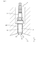
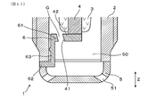
- FIG. 1 is a cross-sectional view taken along the axial direction near the tip of the spark plug in the first embodiment.
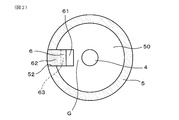
- FIG. 2 is a cross-sectional view taken along the line II-II of FIG.
- FIG. 3 is a front view of the spark plug attached to the internal combustion engine according to the first embodiment.
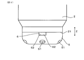
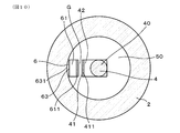
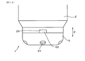
- FIG. 4 is a front view of the vicinity of the tip of the spark plug in the first embodiment.
- FIG. 5 is a cross-sectional explanatory view showing the state of airflow and electric discharge in the first embodiment.
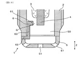
- FIG. 6 is a cross-sectional view taken along the axial direction near the tip of the spark plug in the second embodiment.
- FIG. 7 is a cross-sectional view of an example of the ground electrode in the second embodiment.
- FIG. 8 is a cross-sectional view of the ground electrode attached to the housing in the modified form of the second embodiment.
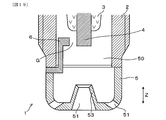
- FIG. 9 is a cross-sectional view taken along the axial direction near the tip of the spark plug in the third embodiment.
- FIG. 10 is a cross-sectional view taken along the line XX of FIG.
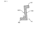
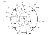
- FIG. 11 is an explanatory view of the spark plug seen from the tip side in the fourth embodiment.
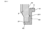
- FIG. 12 is a cross-sectional explanatory view of the ground electrode in the fourth embodiment, which is a view corresponding to the XII-XII cross section of FIG. FIG.
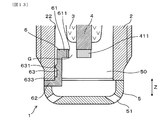
- FIG. 13 is a cross-sectional view taken along the axial direction near the tip of the spark plug in the fifth embodiment.
- FIG. 14 is a front view of the vicinity of the tip of the spark plug in the sixth embodiment.
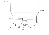
- FIG. 15 is a front view of the vicinity of the tip of another spark plug in the sixth embodiment.
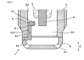
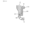
- FIG. 16 is a cross-sectional view showing a state in which the ground electrode is attached to the housing in the seventh embodiment.
- FIG. 17 is a cross-sectional view taken along the axial direction near the tip of the spark plug in the eighth embodiment.
- FIG. 18 is a cross-sectional view taken along the axial direction near the tip of the spark plug in the ninth embodiment.
- FIG. 19 is a cross-sectional view taken along the axial direction near the tip of the spark plug in the tenth embodiment.
- the spark plug 1 for an internal combustion engine of this embodiment has a tubular insulating insulator 3, a center electrode 4, a tubular housing 2, a ground electrode 6, and a plug cover 5. ..
- the center electrode 4 is held on the inner peripheral side of the insulating insulator 3 and protrudes from the insulating insulator 3 to the tip side.
- the housing 2 holds the insulating insulator 3 on the inner peripheral side.
- the ground electrode 6 forms a discharge gap G with the center electrode 4 on the inner peripheral side of the housing 2.
- the plug cover 5 is provided at the tip of the housing 2 so as to cover the auxiliary combustion chamber 50 in which the discharge gap G is arranged.
- the plug cover 5 is provided with a jet hole 51 for communicating the auxiliary combustion chamber 50 to the outside.
- the ground electrode 6 has a discharge side end portion 61 facing the discharge gap G and a joint side end portion 62 joined to the housing 2. As shown in FIG. 1, the discharge side end portion 61 is arranged on the base end side in the axial direction Z with respect to the joint side end portion 62.
- the spark plug 1 of this embodiment can be used as an ignition means in an internal combustion engine such as an automobile or a cogeneration engine, for example. Then, as shown in FIG. 3, one end of the spark plug 1 in the axial direction Z is arranged in the combustion chamber of the internal combustion engine.
- the combustion chamber of this internal combustion engine is referred to as a "main combustion chamber 11" as opposed to the above-mentioned "secondary combustion chamber 50".
- the side exposed to the main combustion chamber 11 is referred to as the distal end side, and the opposite side thereof is referred to as the proximal end side.
- the plug cover 5 is joined to the tip of the housing 2 by welding or the like. In a state where the spark plug 1 is attached to the internal combustion engine, the plug cover 5 separates the sub-combustion chamber 50 from the main combustion chamber 11.
- the plug cover 5 is formed with a plurality of injection holes 51. Each injection hole 51 is inclined toward the outer peripheral side toward the tip side. The flame generated in the sub-combustion chamber 50 is ejected from the injection hole 51 to the main combustion chamber 11.
- the ground electrode 6 has a relay portion 63 that connects the joint side end portion 62 and the discharge side end portion 61 in the axial direction Z.
- the joint side end portion 62 is joined to the tip surface 21 of the housing 2.
- the relay portion 63 is arranged along the inner peripheral surface 22 of the housing 2.
- the relay unit 63 is erected in the axial direction Z.
- the ground electrode 6 is composed of, for example, a metal member made of a nickel-based alloy.
- the discharge side end portion 61 projects from the base end portion of the relay portion 63 in a direction orthogonal to the axial direction Z.
- the joint side end portion 62 projects from the tip end portion of the relay portion 63 in a direction orthogonal to the axial direction Z and to the side opposite to the joint side end portion 62.
- the ground electrode 6 is attached so that the direction from the joint side end portion 62 toward the discharge side end portion 61 is toward the plug central axis in the plug radial direction when viewed from the axial direction Z. ing.
- the central axis of the plug means the central axis of the spark plug 1
- the radial direction of the plug means the direction along a straight line orthogonal to the central axis of the plug.
- the ground electrode 6 is joined in a state where the base end side surface 621 of the joining side end portion 62 is in surface contact with the tip surface of the housing 2.
- the discharge side end 61 of the ground electrode 6 is arranged to face the center electrode 4 from the plug radial direction.
- the discharge side end portion 61 is arranged to face the outer peripheral surface of the tip end portion of the center electrode 4.
- a discharge gap G is formed between the discharge side end portion 61 and the outer peripheral surface of the center electrode 4. That is, the end surface of the discharge side end portion 61 on the plug central axis side faces the outer peripheral surface of the center electrode 4 to form a discharge surface.
- the joint side end portion 62 is arranged in the base end notch portion 52 provided in the plug cover 5.
- the plug cover 5 is joined to the tip end portion of the housing 2, and the base end notch 52 is formed at a part of the end edge on the joint side.
- a joint-side end 62 of the ground electrode 6 is arranged between the base end notch 52 and the front end surface of the housing 2. It is also possible that the joint side end portion 62 and the plug cover 5 are joined to each other by welding or the like. However, the joint side end portion 62 may be configured not to be joined to the plug cover 5.
- the ground electrode 6 has the joint side end 62 arranged on the tip side of the tip of the housing 2 and the discharge side end 61 arranged on the proximal end side of the tip of the housing 2. There is. Along with this, the discharge gap G is formed on the proximal end side of the housing 2 with respect to the distal end end. Further, the tip of the center electrode 4 is arranged on the proximal end side of the tip of the housing 2.
- Housing 2 is made of a metal such as low carbon steel. As shown in FIGS. 1 and 3, the housing 2 has a mounting screw portion 23 on the outer peripheral surface. As shown in FIG. 3, the spark plug 1 is attached to the internal combustion engine by screwing the mounting screw portion 23 into the female screw portion of the plug hole 12 provided in the engine head or the like of the internal combustion engine. The spark plug 1 is attached to an internal combustion engine with a part of the tip side exposed to the main combustion chamber 11.
- the ground electrode 6 has a discharge side end portion 61 arranged on the base end side in the axial direction Z with respect to the joint side end portion 62. Therefore, the discharge gap G can be formed closer to the base end side than the tip end portion of the housing 2 while joining the joining side end portion 62 of the ground electrode 6 to the tip end portion of the housing 2. As a result, the manufacturing process of the spark plug 1 provided with the discharge gap G on the inner peripheral side of the housing 2 can be simplified.
- the plug cover 5 In the spark plug 1 in which the auxiliary combustion chamber 50 is formed by providing the plug cover 5 at the tip of the housing 2, the plug cover 5 is exposed to the main combustion chamber 11 as shown in FIG. Therefore, the temperature of the plug cover 5 tends to rise. If the temperature of the plug cover 5 rises too much, problems such as pre-ignition are likely to occur. Therefore, it is required to reduce the amount of protrusion of the plug cover 5 to the main combustion chamber 11 as much as possible. Therefore, as shown in FIG. 1, by arranging the discharge gap G on the inner peripheral side of the housing 2, that is, on the proximal end side of the tip of the housing 2, as shown in FIG. 3, the plug cover 5 from the housing 2 It is possible to reduce the amount of protrusion. As a result, the heat of the plug cover 5 is easily released to the engine head via the housing 2, and the temperature rise of the plug cover 5 is easily suppressed.
- a strong flame jet can be injected into the main combustion chamber 11 by sufficiently growing the flame generated in the sub-combustion chamber 50 and then ejecting the flame from the injection hole 51. From this point of view, there is also a request to increase the distance in the axial direction Z between the discharge gap G and the injection hole 51. In order to meet both the request and the request to reduce the protrusion amount of the plug cover 5, it is required to form the discharge gap G on the proximal end side of the housing 2 with respect to the distal end end.
- the process of attaching the ground electrode to the housing 2 becomes complicated.
- a step of forming a through hole in the housing 2 is required, which complicates the manufacturing process.
- the housing 2 is provided with a through hole at the position where the mounting screw portion 23 is formed, a part of the mounting screw portion 23 is missing, which affects the fastening state of the spark plug 1 to the engine head. Is also a concern.
- the ground electrode 6 is configured such that the discharge side end portion 61 is arranged on the base end side in the axial direction Z with respect to the joint side end portion 62. This makes it easy to join the ground electrode 6 to the tip end portion of the housing 2 and form the discharge gap G on the proximal end side of the housing 2 tip end without providing a particularly complicated process.
- the discharge side end portion 61 of the ground electrode 6 is arranged to face the center electrode 4 from the plug radial direction.
- the airflow A in the auxiliary combustion chamber 50 tends to stretch the discharge S generated in the discharge gap G.
- the ignitability in the sub-combustion chamber 50 can be improved, and by extension, the ignitability in the main combustion chamber 11 can be improved.
- an air flow is introduced from the injection hole 51 into the auxiliary combustion chamber 50 in the compression stroke of the internal combustion engine or the like. It is conceivable that this airflow A forms a tumble flow in the auxiliary combustion chamber 50. That is, it is conceivable that after being introduced from a part of the injection holes 51, an air flow A is once formed toward the proximal end side of the discharge gap G and then toward the distal end side in the axial direction Z. In this case, by providing the discharge gap G at a position facing the outer peripheral surface of the center electrode 4 from the plug radial direction, the discharge S generated in the discharge gap G is easily stretched toward the tip side. Then, a flame is formed in the auxiliary combustion chamber 50, and it becomes easy to grow. As a result, the ignitability can be improved.
- the ground electrode 6 has a relay unit 63. Then, the end portion 62 on the joining side is joined to the tip surface 21 of the housing 2, and the relay portion 63 is arranged along the inner peripheral surface 22 of the housing 2. Thereby, the ground electrode 6 can be more easily and accurately joined to the tip end portion of the housing 2, and the discharge side end portion 61 can be opposed to the center electrode 4 on the inner peripheral side of the housing 2. By increasing the length of the relay portion 63 in the axial direction Z, it becomes easier to form the discharge gap G on the proximal end side. Further, by arranging the relay unit 63 along the inner peripheral surface 22 of the housing 2, it is possible to prevent the relay unit 63 from hindering the air flow and flame growth in the auxiliary combustion chamber 50.
- the spark plug 1 of the present embodiment can improve the ignitability. That is, in this case, the airflow passing through the discharge gap G extends the discharge along the peripheral direction of the plug.
- a tapered surface is provided on the inner peripheral side surface 632 of the relay portion 63 of the ground electrode 6 as in the fourth embodiment (see FIGS. 11 and 12) described later. It is also effective to form.
- a tumble flow is generated in the auxiliary combustion chamber 50, it is also effective to incline the pair of discharge surfaces as in the eighth embodiment (see FIG. 17) described later.
- the relay portion 63 has a protrusion 631 protruding toward the inner peripheral surface 22 of the housing 2.
- the protrusion 631 is formed at a position on the distal end side of the discharge side end portion 61 and on the proximal end side of the joint side end portion 62 in the axial direction Z.
- the protrusion 631 is in contact with the inner peripheral surface 22 of the housing 2.
- the relay portion 63 is provided with a protrusion 631. Therefore, when the ground electrode 6 is attached to the housing 2, it is easy to accurately position the ground electrode 6 in the radial direction of the plug. That is, by appropriately setting the protrusion height of the protrusion 631 in advance, when the protrusion 631 is brought into contact with the inner peripheral surface 22 of the housing 2, the position of the discharge side end portion 61 in the plug radial direction can be determined. You can decide exactly. Then, a discharge gap G having an appropriate size can be easily and accurately formed.
- the discharge side end portion 61 becomes the center electrode. Move to the 4 side. That is, in the stage before fixing the ground electrode 6, the size of the discharge gap G can be finely adjusted by sliding the joint side end portion 62 in the plug radial direction with the protrusion 631 as a fulcrum. It becomes. As a result, the discharge gap G arranged on the proximal end side of the housing 2 can be easily finely adjusted. In addition, it has the same effect as that of the first embodiment.
- the angle ⁇ formed between the joint side end portion 62 and the relay portion 63 an acute angle. Be done.
- the protrusion 631 can be pressed against the inner peripheral surface 22 of the housing 2 to elastically deform the ground electrode 6 so that the angle ⁇ is widened.
- the angle ⁇ at this time, the position of the discharge side end portion 61 of the ground electrode 6 can be adjusted, and the size of the discharge gap G can be adjusted.
- a protrusion 221 protruding toward the relay portion 63 of the ground electrode 6 can be provided on the inner peripheral surface 22 of the housing 2. Also in this case, the same effect as the above-mentioned effect can be obtained. However, from the viewpoint of productivity and the like, it is preferable that the ground electrode 6 is provided with the protrusion 631.
- the center electrode 4 has a flat discharge surface 41 on the discharge gap G side.
- an extension portion 42 is provided at the tip end portion of the center electrode 4.
- the extending portion 42 projects toward the ground electrode 6 side and outward from the base material 40 of the center electrode 4 in the plug radial direction.
- the extending portion 42 is joined to the tip surface of the base material 40 as a separate member from the base material 40 of the center electrode 4.
- the extending portion 42 can be a member having a substantially rectangular shape.
- the flat surface provided on the extending portion 42 faces the discharge side end portion 61 of the ground electrode 6. That is, the flat surface on the discharge gap G side of the extending portion 42 becomes the above-mentioned flat discharge surface 41.
- the chip 411 is provided on the flat discharge surface 41 in the extending portion 42.
- the chip 611 is also provided at the discharge side end portion 61 of the ground electrode 6.
- the chips 411 and 611 can be made of, for example, a noble metal such as iridium or platinum or an alloy thereof.
- the chip 411 in the center electrode 4 and the chip 611 in the ground electrode 6 may not be provided. Others are the same as in the second embodiment.
- the surface of the center electrode 4 facing the discharge gap G a flat flat discharge surface 41, it is possible to suppress the expansion of the discharge gap G due to electrode wear. That is, if the side surface of the columnar center electrode 4 is a discharge surface as in the first embodiment, the discharge gap G tends to expand due to electrode wear due to discharge. On the other hand, by providing the flat discharge surface 41, it is possible to suppress the expansion of the discharge gap G.
- the chip 411 on the flat discharge surface 41, the expansion of the discharge gap G is further suppressed. In addition, it has the same effect as that of the second embodiment.
- this embodiment is configured so that a swirl flow is formed in the auxiliary combustion chamber 50. That is, in the plug cover 5, the injection hole 51 is formed so that the swirl flow is formed in the auxiliary combustion chamber 50.
- the inner peripheral side surface 632 of the relay portion 63 is inclined toward the plug central axis side from the upstream side to the downstream side of the swirl flow As.
- the swirl flow As is a spiral flow centered on the plug central axis PC.
- the plug cover 5 has a plurality of injection holes 51.
- the injection hole extension line 51L of each injection hole 51 is formed so as to deviate from the plug central axis PC.
- the angle ⁇ between the virtual straight line VL extending in the plug radial direction passing through the injection hole 51 and the plug central axis PC and the injection hole extension line 51L is an acute angle.
- the angles ⁇ with respect to each injection hole 51 are equivalent to each other.
- the inner peripheral side surface 632 of the relay portion 63 of the ground electrode 6 is a tapered surface.
- the inner peripheral side surface 632 may be curved as long as it is inclined toward the plug central axis PC side from the upstream side to the downstream side of the swirl flow As.
- the inner peripheral side surface 632 is preferably a concave curved surface, but may also be a convex curved surface. Others are the same as in the third embodiment.
- the inner peripheral side surface 632 of the relay unit 63 can guide the swirl flow As.
- the airflow passing near the discharge gap G is gradually guided to the plug central axis PC side while flowing along the plug circumferential direction as a swirl flow As.
- the discharge formed in the discharge gap G is more likely to be extended from the central portion in the sub-combustion chamber 50.
- a flame can be generated at a position further away from the side wall of the auxiliary combustion chamber 50, that is, the inner peripheral surface 22 of the housing 2.
- the flame jet ejected from the sub-combustion chamber 50 to the main combustion chamber 11 can be strengthened.
- it has the same effect as that of the third embodiment.
- an additional protrusion 633 protruding from the relay portion 63 in the same direction as the protrusion 631 is provided at a position on the tip side of the relay portion 63 of the ground electrode 6 with respect to the protrusion 631. Is.
- the additional protrusion 633 is formed between the relay portion 63 and the joint side end portion 62.
- the chip 411 is bonded to the tip surface of the center electrode 4. Further, the chip 611 is also bonded to the discharge side end portion 61 of the ground electrode 6.
- the tip 411 of the center electrode 4 and the tip 611 of the ground electrode 6 face each other in the plug radial direction.
- a discharge gap G is formed between the tip 411 of the center electrode 4 and the tip 611 of the ground electrode 6 facing each other in the radial direction of the plug. Others are the same as in the second embodiment.
- the relay portion 63 of the ground electrode 6 can be brought into contact with the inner peripheral surface 22 of the housing 2 at both the protrusion 631 and the additional protrusion 633. Therefore, when the ground electrode 6 is assembled to the housing 2, the mounting posture of the ground electrode 6 can be stabilized. As a result, it is easy to accurately form the size of the discharge gap G. In addition, it has the same effect as that of the second embodiment.
- the joint side end portion 62 of the ground electrode 6 is arranged in the tip notch portion 24 provided at the tip end of the housing 2.
- the plug cover 5 is not provided with a notch. That is, in the present embodiment, the plug cover 5 does not have the base end notch 52 shown in the first embodiment.
- the housing 2 is provided with a tip notch 24, and the plug cover 5 is also provided with a base end notch 52.
- the housing 2 and the plug cover 5 are joined to each other so that the tip notch 24 and the proximal notch 52 overlap each other in the axial direction Z.
- the joint side end portion 62 of the ground electrode 6 is arranged in the space including the tip notch portion 24 and the proximal end notch portion 52. Others are the same as those in the first embodiment.
- the tip notch 24 exerts a positioning function when the ground electrode 6 is assembled to the housing 2. This makes it possible to easily assemble the ground electrode 6 to the housing 2. Further, in the case of the spark plug 1 shown in FIG. 14, the structure of the plug cover 5 can be simplified. In addition, it has the same effect as that of the first embodiment.
- the joint side end portion 62 of the ground electrode 6 is not exposed to the outer peripheral side of the housing 2 and the plug cover 5. That is, the joint side end portion 62 of the ground electrode 6 is arranged inside the outer peripheral surface of the housing 2 and inside the outer peripheral surface of the plug cover 5. The joint side end portion 62 is engaged with a part of the tip surface 21 of the housing 2 on the inner peripheral side. Others are the same as those in the first embodiment. Also in the case of this embodiment, the same action and effect as in the first embodiment are obtained.
- this embodiment is a form in which a pair of discharge surfaces facing each other via the discharge gap G are inclined so as to be toward the tip end side in the axial direction Z and toward the plug central axis side. That is, the end surface of the discharge side end 61 of the ground electrode 6 facing the discharge gap G is inclined toward the plug center axis side toward the tip end side in the axial direction Z. Further, the flat discharge surface 41 of the center electrode 4 is also inclined toward the plug center axis side toward the tip end side in the axial direction Z.
- neither the ground electrode 6 nor the center electrode 4 is provided with a tip.
- chips may be provided on one or both of the ground electrode 6 and the center electrode 4. Others are the same as in the third embodiment.
- this embodiment is a form in which a jet hole 51 penetrating in the axial direction Z is provided at a position overlapping the plug central axis in the plug cover 5.
- the injection hole 51 in the axial direction Z is formed at a position overlapping the center electrode 4 in the axial direction Z.
- Others are the same as those in the first embodiment. Also in this embodiment, the same effect as that of the first embodiment can be obtained.
- this embodiment is a form of a spark plug 1 having a protruding tubular body 53 protruding from the tip of the plug cover 5 toward the auxiliary combustion chamber 50.
- the projecting tubular body 53 has a substantially conical shape in the axial direction Z so that the diameter decreases toward the proximal end side from the tip end portion, and penetrates in the axial direction Z.
- the through space inside the protruding cylindrical body 53 is one of the injection holes 51.
- Others are the same as those in the first embodiment. Also in this embodiment, it has the same effect as that of the first embodiment.
Landscapes
- Spark Plugs (AREA)
Abstract
スパークプラグ(1)は、筒状の絶縁碍子(3)と、絶縁碍子(3)の内周側に保持されると共に絶縁碍子(3)から先端側に突出する中心電極(4)と、絶縁碍子(3)を内周側に保持する筒状のハウジング(2)と、ハウジング(2)の内周側において、中心電極(4)との間に放電ギャップ(G)を形成する接地電極(6)と、放電ギャップ(G)が配される副燃焼室(50)を覆うようハウジング(2)の先端部に設けられたプラグカバー(5)と、を有する。プラグカバー(5)には、副燃焼室(50)を外部に連通させる噴孔(51)が設けられている。接地電極(6)は、放電ギャップ(G)に面する放電側端部(61)と、ハウジング(2)に接合された接合側端部(62)とを有する。放電側端部(61)が、接合側端部(62)よりも、軸方向Zの基端側に配置されている。
Description
本出願は、2020年6月9日に出願された日本出願番号2020-100406号に基づくもので、ここにその記載内容を援用する。
本開示は、内燃機関用のスパークプラグに関する。
ハウジングの先端部にプラグカバーを設けて副燃焼室を形成したスパークプラグがある。かかるスパークプラグにおいて、放電ギャップをハウジングの先端よりも基端側に形成した構成が、特許文献1に開示されている。特許文献1に開示されたスパークプラグは、放電ギャップを上記のような位置に設けることで、ハウジングからプラグカバーの先端までの距離を小さくすることが可能となり、プラグカバーの熱引き性を向上させることができる。このような構成を実現すべく、上記スパークプラグにおいては、ハウジングの側壁に設けた貫通孔に、接地電極を貫通させて取り付けてある。
特許文献1に開示されたスパークプラグにおいては、ハウジングの側壁に貫通孔を設けると共に、貫通孔に接地電極を貫通させて接合する必要がある。それゆえ、スパークプラグの製造工程が複雑となる。
本開示は、製造工程の簡素化を可能とする、内燃機関用のスパークプラグを提供しようとするものである。
本開示の一態様は、筒状の絶縁碍子と、
該絶縁碍子の内周側に保持されると共に該絶縁碍子から先端側に突出する中心電極と、
上記絶縁碍子を内周側に保持する筒状のハウジングと、
該ハウジングの内周側において、上記中心電極との間に放電ギャップを形成する接地電極と、
上記放電ギャップが配される副燃焼室を覆うよう上記ハウジングの先端部に設けられたプラグカバーと、を有し、
上記プラグカバーには、上記副燃焼室を外部に連通させる噴孔が設けられており、
上記接地電極は、上記放電ギャップに面する放電側端部と、上記ハウジングに接合された接合側端部とを有し、
上記放電側端部が、上記接合側端部よりも、軸方向の基端側に配置されている、内燃機関用のスパークプラグにある。
上記内燃機関用のスパークプラグにおいて、接地電極は、上記放電側端部が上記接合側端部よりも、軸方向の基端側に配置されている。それゆえ、ハウジングの先端部又はその近傍に、接地電極の接合側端部を接合しつつ、放電ギャップをハウジングの先端部よりも基端側に形成することができる。その結果、ハウジングの内周側に放電ギャップを備えたスパークプラグの製造工程を、簡素化することができる。
以上のごとく、上記態様によれば、製造工程の簡素化を可能とする、内燃機関用のスパークプラグを提供することができる。
本開示についての上記目的およびその他の目的、特徴や利点は、添付の図面を参照しながら下記の詳細な記述により、より明確になる。その図面は、
図1は、実施形態1における、スパークプラグの先端部付近の、軸方向に沿った断面図であり、
図2は、図1のII-II線矢視断面図であり、
図3は、実施形態1における、内燃機関に取り付けられたスパークプラグの正面図であり、
図4は、実施形態1における、スパークプラグの先端部付近の正面図であり、
図5は、実施形態1における、気流と放電の様子を示す断面説明図であり、
図6は、実施形態2における、スパークプラグの先端部付近の、軸方向に沿った断面図であり、
図7は、実施形態2における、接地電極の一例の断面図であり、
図8は、実施形態2の変形形態における、ハウジングに取り付けられた接地電極の断面図であり、
図9は、実施形態3における、スパークプラグの先端部付近の、軸方向に沿った断面図であり、
図10は、図9のX-X線矢視断面図であり、
図11は、実施形態4における、先端側から見たスパークプラグの説明図であり、
図12は、実施形態4における、接地電極の断面説明図であって、図9のXII-XII断面相当の図であり、
図13は、実施形態5における、スパークプラグの先端部付近の、軸方向に沿った断面図であり、
図14は、実施形態6における、スパークプラグの先端部付近の正面図であり、
図15は、実施形態6における、他のスパークプラグの先端部付近の正面図であり、
図16は、実施形態7における、ハウジングに対する接地電極の取り付け状態を示す断面図であり、
図17は、実施形態8における、スパークプラグの先端部付近の、軸方向に沿った断面図であり、
図18は、実施形態9における、スパークプラグの先端部付近の、軸方向に沿った断面図であり、
図19は、実施形態10における、スパークプラグの先端部付近の、軸方向に沿った断面図である。
(実施形態1)
内燃機関用のスパークプラグに係る実施形態について、図1~図5を参照して説明する。
本形態の内燃機関用のスパークプラグ1は、図1に示すごとく、筒状の絶縁碍子3と、中心電極4と、筒状のハウジング2と、接地電極6と、プラグカバー5と、を有する。
内燃機関用のスパークプラグに係る実施形態について、図1~図5を参照して説明する。
本形態の内燃機関用のスパークプラグ1は、図1に示すごとく、筒状の絶縁碍子3と、中心電極4と、筒状のハウジング2と、接地電極6と、プラグカバー5と、を有する。
中心電極4は、絶縁碍子3の内周側に保持されると共に絶縁碍子3から先端側に突出している。ハウジング2は、絶縁碍子3を内周側に保持する。図1、図2に示すごとく、接地電極6は、ハウジング2の内周側において、中心電極4との間に放電ギャップGを形成する。プラグカバー5は、放電ギャップGが配される副燃焼室50を覆うようハウジング2の先端部に設けられている。
プラグカバー5には、副燃焼室50を外部に連通させる噴孔51が設けられている。接地電極6は、放電ギャップGに面する放電側端部61と、ハウジング2に接合された接合側端部62とを有する。図1に示すごとく、放電側端部61が、接合側端部62よりも、軸方向Zの基端側に配置されている。
本形態のスパークプラグ1は、例えば、自動車、コージェネレーション等の内燃機関における着火手段として用いることができる。そして、図3に示すごとく、スパークプラグ1の軸方向Zの一端を、内燃機関の燃焼室に配置する。この内燃機関の燃焼室を、上述の「副燃焼室50」に対して、「主燃焼室11」という。スパークプラグ1の軸方向Zにおいて、主燃焼室11に露出する側を先端側、その反対側を基端側というものとする。
図1に示すごとく、プラグカバー5は、ハウジング2の先端部に溶接等によって接合されている。スパークプラグ1が内燃機関に取り付けられた状態において、プラグカバー5は、副燃焼室50を主燃焼室11と区画している。本形態において、プラグカバー5には、複数の噴孔51が形成されている。各噴孔51は、先端側へ向かうほど外周側へ向かうように傾斜している。副燃焼室50にて生じた火炎は、噴孔51から主燃焼室11へ噴出する。
図1に示すごとく、接地電極6は、接合側端部62と放電側端部61とを軸方向Zに繋ぐ中継部63を有する。接合側端部62は、ハウジング2の先端面21に接合されている。中継部63は、ハウジング2の内周面22に沿って配置されている。中継部63は、軸方向Zに立設している。
接地電極6は、例えば、ニッケル基合金からなる金属部材によって構成される。放電側端部61は、中継部63の基端部から軸方向Zに直交する方向に突出している。接合側端部62は、中継部63の先端部から、軸方向Zに直交する方向であって、接合側端部62と反対側へ突出している。図2に示すごとく、軸方向Zから見て、接合側端部62から放電側端部61へ向かう向きが、プラグ径方向においてプラグ中心軸に向う向きとなるように、接地電極6が取り付けられている。なお、プラグ中心軸は、スパークプラグ1の中心軸を意味し、プラグ径方向は、プラグ中心軸に直交する直線に沿った方向を意味するものとする。
図1、図4に示すごとく、接地電極6は、接合側端部62における基端側面621が、ハウジング2の先端面に面接触する状態にて接合されている。そして、接地電極6の放電側端部61は、中心電極4に対してプラグ径方向から対向配置されている。放電側端部61が、中心電極4の先端部の外周面に対向配置されている。放電側端部61と中心電極4の外周面との間に、放電ギャップGが形成されている。すなわち、放電側端部61におけるプラグ中心軸側の端面が、中心電極4の外周面に対向して、放電面を構成している。
本形態において、接合側端部62は、プラグカバー5に設けた基端切欠部52に配置されている。上述のように、プラグカバー5は、ハウジング2の先端部に接合されているが、その接合側の端縁の一部に、基端切欠部52が形成されている。この基端切欠部52とハウジング2の先端面との間に、接地電極6の接合側端部62が配置されている。接合側端部62とプラグカバー5とは、互いに溶接等にて接合されているものとすることもできる。ただし、接合側端部62は、プラグカバー5に対して接合されていない構成とすることもできる。
このように、本形態において、接地電極6は、接合側端部62がハウジング2の先端よりも先端側に配置され、放電側端部61がハウジング2の先端よりも基端側に配置されている。これに伴い、放電ギャップGはハウジング2の先端よりも基端側に形成されている。また、中心電極4の先端は、ハウジング2の先端よりも基端側に配置されている。
ハウジング2は、例えば低炭素鋼等の金属からなる。ハウジング2は、図1、図3に示すごとく、外周面に取付ネジ部23を有する。図3に示すごとく、取付ネジ部23が内燃機関のエンジンヘッド等に設けられたプラグホール12の雌ネジ部に螺合することで、内燃機関にスパークプラグ1が取り付けられる。スパークプラグ1は、先端側の一部を主燃焼室11に露出させた状態にて、内燃機関に取り付けられる。
次に、本形態の作用効果につき説明する。
上記内燃機関用のスパークプラグ1において、接地電極6は、放電側端部61が接合側端部62よりも、軸方向Zの基端側に配置されている。それゆえ、ハウジング2の先端部に接地電極6の接合側端部62を接合しつつ、放電ギャップGをハウジング2の先端部よりも基端側に形成することができる。その結果、ハウジング2の内周側に放電ギャップGを備えたスパークプラグ1の製造工程を、簡素化することができる。
上記内燃機関用のスパークプラグ1において、接地電極6は、放電側端部61が接合側端部62よりも、軸方向Zの基端側に配置されている。それゆえ、ハウジング2の先端部に接地電極6の接合側端部62を接合しつつ、放電ギャップGをハウジング2の先端部よりも基端側に形成することができる。その結果、ハウジング2の内周側に放電ギャップGを備えたスパークプラグ1の製造工程を、簡素化することができる。
ハウジング2の先端部にプラグカバー5を設けて副燃焼室50を形成したスパークプラグ1においては、図3に示すごとく、プラグカバー5が主燃焼室11に露出する。そのため、プラグカバー5の温度が上昇しやすい。プラグカバー5の温度が上昇しすぎると、プレイグニッション等の不具合を招きやすくなるため、極力、主燃焼室11へのプラグカバー5の突出量を小さくすることが求められる。そこで、図1に示すごとく、放電ギャップGをハウジング2の内周側、すなわち、ハウジング2の先端よりも基端側に配置することで、図3に示すごとく、ハウジング2からのプラグカバー5の突出量を小さくすることが可能となる。これにより、プラグカバー5の熱がハウジング2を介してエンジンヘッドに放出されやすくなり、プラグカバー5の温度上昇を抑制しやすくなる。
その一方で、副燃焼室50において生じた火炎を充分に成長させた後に、噴孔51から火炎を噴出させることにより、強い火炎ジェットを主燃焼室11に噴射させることができる。かかる観点から、放電ギャップGと噴孔51との間の軸方向Zの距離を大きくしたいという要請もある。かかる要請と、上述のプラグカバー5の突出量を小さくしたいという要請との双方に対応するためには、ハウジング2の先端よりも基端側に放電ギャップGを形成することが求められる。
ところが、放電ギャップGをハウジング2の先端よりも基端側に形成する場合、ハウジング2に対する接地電極の取付工程が複雑となる。例えば、ハウジング2にプラグ径方向の貫通孔を設けて、その貫通孔に接地電極を貫通させてハウジング2に取り付けることが考えられる。しかし、かかる場合には、ハウジング2に貫通孔を形成する工程が必要になり、製造工程が複雑となる。また、取付ネジ部23が形成された位置においてハウジング2に貫通孔を設ける場合には、取付ネジ部23の一部が欠損することとなり、エンジンヘッドへのスパークプラグ1の締結状態に影響することも懸念される。
したがって、ハウジング2の先端よりも基端側に放電ギャップGを備えたスパークプラグ1を、簡素な製造工程にて製造することが求められる。そこで、上述のように、接地電極6を、放電側端部61が接合側端部62よりも、軸方向Zの基端側に配置される構成とした。これにより、特に複雑な工程を設けることなく、接地電極6をハウジング2の先端部に接合して、ハウジング2の先端よりも基端側に放電ギャップGを形成することが容易となる。
また、接地電極6の放電側端部61は、中心電極4に対してプラグ径方向から対向配置されている。これにより、図5に示すごとく、副燃焼室50における気流Aが、放電ギャップGにおいて生じた放電Sを引き伸ばしやすくなる。これにより、副燃焼室50における着火性を向上させ、ひいては、主燃焼室11における着火性を向上させることができる。
例えば、図5に示すごとく、内燃機関の圧縮行程等において、噴孔51から副燃焼室50に気流が導入される。この気流Aが、副燃焼室50において、タンブル流を形成することが考えられる。つまり、一部の噴孔51から導入された後、一旦、放電ギャップGよりも基端側に向かい、さらにその後、軸方向Zの先端側へ向かう気流Aが形成されることが考えられる。この場合、中心電極4の外周面にプラグ径方向から対向する位置に、放電ギャップGを設けることで、放電ギャップGに生じた放電Sが先端側へ引き伸ばされやすくなる。そうすると、副燃焼室50において火炎が形成され、成長しやすくなる。その結果、着火性を向上させることができる。
また、図1に示すごとく、接地電極6は中継部63を有する。そして、接合側端部62がハウジング2の先端面21に接合され、中継部63がハウジング2の内周面22に沿って配置されている。これにより、一層容易かつ正確に、接地電極6をハウジング2の先端部に接合しつつ、放電側端部61をハウジング2の内周側において中心電極4に対向させることができる。そして、中継部63の軸方向Zの長さを長くすることで、より基端側に放電ギャップGを形成することも容易となる。また、中継部63がハウジング2の内周面22に沿って配置されることで、中継部63が副燃焼室50における気流や火炎成長の妨げになることを抑制することができる。
なお、上述の図5及びこれを用いた説明においては、副燃焼室50にタンブル流が形成される場合について説明したが、副燃焼室50にスワール流(図11の矢印As参照)が形成される場合においても、本形態のスパークプラグ1は、着火性を向上させることができる。すなわち、この場合、放電ギャップGを通過する気流によって、プラグ周方向に沿って放電が引き伸ばされることとなる。
なお、副燃焼室50にスワール流を生じさせる場合には、後述する実施形態4(図11、図12参照)のように、接地電極6の中継部63の内周側面632に、テーパ面を形成することも有効である。
一方、副燃焼室50にタンブル流を生じさせる場合には、後述する実施形態8(図17参照)のように、一対の放電面を傾斜させることも有効である。
一方、副燃焼室50にタンブル流を生じさせる場合には、後述する実施形態8(図17参照)のように、一対の放電面を傾斜させることも有効である。
以上のごとく、本形態によれば、製造工程の簡素化を可能とする、内燃機関用のスパークプラグを提供することができる。
(実施形態2)
本形態は、図6に示すごとく、中継部63が、ハウジング2の内周面22に向って突出する突起部631を有する形態である。
突起部631は、軸方向Zにおいて、放電側端部61よりも先端側であり、接合側端部62よりも基端側の位置に、形成されている。突起部631は、ハウジング2の内周面22に当接している。
本形態は、図6に示すごとく、中継部63が、ハウジング2の内周面22に向って突出する突起部631を有する形態である。
突起部631は、軸方向Zにおいて、放電側端部61よりも先端側であり、接合側端部62よりも基端側の位置に、形成されている。突起部631は、ハウジング2の内周面22に当接している。
その他は、実施形態1と同様である。なお、実施形態2以降において用いた符号のうち、既出の実施形態において用いた符号と同一のものは、特に示さない限り、既出の実施形態におけるものと同様の構成要素等を表す。
本形態においては、中継部63に突起部631が設けられている。そのため、接地電極6をハウジング2に取り付ける際、プラグ径方向の位置決めを正確に行いやすい。すなわち、予め突起部631の突出高さを適切に設定しておくことで、突起部631をハウジング2の内周面22に当接させたとき、放電側端部61のプラグ径方向の位置を正確に決めることができる。そうすると、適切な大きさの放電ギャップGを、容易かつ正確に形成することができる。
また、接地電極6がある程度変形可能な場合、突起部631をハウジング2の内周面22に当接させながら、接合側端部62を外周側へ移動させると、放電側端部61が中心電極4側に移動する。つまり、接地電極6を固定する前の段階においては、突起部631を支点として、接合側端部62をプラグ径方向にスライドさせることで、放電ギャップGの大きさの微調整を行うことも可能となる。これにより、ハウジング2の先端よりも基端側に配される放電ギャップGの微調整を、容易に行うことができる。
その他、実施形態1と同様の作用効果を有する。
その他、実施形態1と同様の作用効果を有する。
なお、ハウジング2に取り付ける前の状態の接地電極6の形状として、図7に示すごとく、接合側端部62と中継部63との間のなす角度αが鋭角となる形状にしておくことも考えられる。この場合には、ハウジング2に取り付ける際に、突起部631をハウジング2の内周面22に押し付けて、上記角度αが広がるように、接地電極6を弾性変形させることができる。このときの角度αの調整により、接地電極6の放電側端部61の位置を調整し、放電ギャップGの大きさを調整することができる。
また、本形態の変形形態として、図8に示すごとく、ハウジング2の内周面22に、接地電極6の中継部63へ向かって突出した突起部221を設けることもできる。この場合にも、上述した作用効果と同様の作用効果を得ることができる。ただし、生産性等の観点では、接地電極6に突起部631を設けた形態が好ましい。
(実施形態3)
本形態は、図9、図10に示すごとく、中心電極4が、放電ギャップG側に、平坦面状の平坦放電面41を有する形態である。
本形態においては、中心電極4の先端部に、延設部42を設けている。延設部42は、接地電極6側へ、中心電極4の母材40からプラグ径方向の外側へ突出している。延設部42は、中心電極4の母材40とは別部材として、母材40の先端面に接合してなる。この延設部42は、略直方形状の部材とすることができる。
本形態は、図9、図10に示すごとく、中心電極4が、放電ギャップG側に、平坦面状の平坦放電面41を有する形態である。
本形態においては、中心電極4の先端部に、延設部42を設けている。延設部42は、接地電極6側へ、中心電極4の母材40からプラグ径方向の外側へ突出している。延設部42は、中心電極4の母材40とは別部材として、母材40の先端面に接合してなる。この延設部42は、略直方形状の部材とすることができる。
延設部42に設けた平坦面が、接地電極6の放電側端部61に対向している。つまり、延設部42における放電ギャップG側の平坦面が、上述の平坦放電面41となる。
本形態において、延設部42における平坦放電面41には、チップ411が設けてある。
本形態において、延設部42における平坦放電面41には、チップ411が設けてある。
また、本形態においては、接地電極6の放電側端部61にも、チップ611が設けてある。チップ411、611は、例えば、イリジウム、白金等の貴金属又はその合金にて構成することができる。
ただし、中心電極4におけるチップ411及び接地電極6におけるチップ611の、いずれか一方若しくは双方を設けない構成とすることもできる。
その他は、実施形態2と同様である。
その他は、実施形態2と同様である。
本形態においては、中心電極4における放電ギャップGに対向する面を、平坦な平坦放電面41とすることにより、電極消耗による放電ギャップGの拡大を抑制することができる。すなわち、実施形態1のように、円柱状の中心電極4の側面を、放電面とすると、放電による電極消耗によって、放電ギャップGが拡大しやすい。これに対して、平坦放電面41を設けることで、放電ギャップGの拡大を抑制することができる。
また、本形態においては、平坦放電面41にチップ411を設けることで、一層、放電ギャップGの拡大が抑制される。
その他、実施形態2と同様の作用効果を有する。
その他、実施形態2と同様の作用効果を有する。
(実施形態4)
本形態は、図11、図12に示すごとく、副燃焼室50にスワール流が形成されるように構成した形態である。
すなわち、プラグカバー5において、副燃焼室50にスワール流が形成されるように、噴孔51を形成してある。そして、中継部63の内周側面632は、スワール流Asの上流側から下流側に向うほどプラグ中心軸側に向うように傾斜している。
本形態は、図11、図12に示すごとく、副燃焼室50にスワール流が形成されるように構成した形態である。
すなわち、プラグカバー5において、副燃焼室50にスワール流が形成されるように、噴孔51を形成してある。そして、中継部63の内周側面632は、スワール流Asの上流側から下流側に向うほどプラグ中心軸側に向うように傾斜している。
図11、図12に示すごとく、スワール流Asは、プラグ中心軸PCを略中心とした螺旋状に流れる気流である。
プラグカバー5は、複数の噴孔51を有する。そして、図11に示すごとく、それぞれの噴孔51の噴孔延長線51Lは、プラグ中心軸PCからずれるよう形成されている。Z方向から見たとき、噴孔51とプラグ中心軸PCとを通過するプラグ径方向に延びる仮想直線VLと、噴孔延長線51Lとの間の角度βは、鋭角である。本形態において、各噴孔51に関する角度βは、互いに同等である。
プラグカバー5は、複数の噴孔51を有する。そして、図11に示すごとく、それぞれの噴孔51の噴孔延長線51Lは、プラグ中心軸PCからずれるよう形成されている。Z方向から見たとき、噴孔51とプラグ中心軸PCとを通過するプラグ径方向に延びる仮想直線VLと、噴孔延長線51Lとの間の角度βは、鋭角である。本形態において、各噴孔51に関する角度βは、互いに同等である。
本形態において、接地電極6の中継部63の内周側面632は、テーパ面となっている。ただし、内周側面632は、スワール流Asの上流側から下流側に向うほどプラグ中心軸PC側に向うように傾斜していれば、曲面状とすることもできる。この場合において、内周側面632は、凹状の曲面とすることが望ましいが、凸状の曲面とすることもできる。
その他は、実施形態3と同様である。
その他は、実施形態3と同様である。
本形態の場合、中継部63の内周側面632が、スワール流Asをガイドすることができる。これにより、放電ギャップG付近を通過する気流は、スワール流Asとしてプラグ周方向に沿って流れつつ、徐々にプラグ中心軸PC側に導かれる。これにより、放電ギャップGにて形成された放電は、副燃焼室50における中心部よりに伸ばされやすくなる。その結果、副燃焼室50の側壁、すなわちハウジング2の内周面22から、より離れた位置において火炎を生じさせることができる。その結果、冷損を抑制して、副燃焼室50における火炎成長を促すことができる。これにより、副燃焼室50から主燃焼室11へ噴出する火炎ジェットを強力にすることができる。
その他、実施形態3と同様の作用効果を有する。
その他、実施形態3と同様の作用効果を有する。
(実施形態5)
本形態は、図13に示すごとく、接地電極6の中継部63における突起部631よりも先端側の位置に、中継部63から突起部631と同じ方向に突出した追加突起部633を設けた形態である。
本形態において、追加突起部633は、中継部63と接合側端部62との間に形成されている。
本形態は、図13に示すごとく、接地電極6の中継部63における突起部631よりも先端側の位置に、中継部63から突起部631と同じ方向に突出した追加突起部633を設けた形態である。
本形態において、追加突起部633は、中継部63と接合側端部62との間に形成されている。
また、本形態においては、中心電極4の先端面にチップ411が接合されている。また、接地電極6の放電側端部61にもチップ611が接合されている。中心電極4のチップ411と接地電極6のチップ611とが、互いにプラグ径方向に対向している。このようにプラグ径方向に対向した中心電極4のチップ411と接地電極6のチップ611との間に、放電ギャップGが形成されている。
その他は、実施形態2と同様である。
その他は、実施形態2と同様である。
本形態においては、突起部631と追加突起部633との双方において、接地電極6の中継部63をハウジング2の内周面22に当接させることができる。それゆえ、ハウジング2への接地電極6の組付け時において、接地電極6の取付姿勢を安定させることができる。その結果、放電ギャップGの大きさを精度よく形成しやすい。
その他、実施形態2と同様の作用効果を有する。
その他、実施形態2と同様の作用効果を有する。
(実施形態6)
本形態は、図14、図15に示すごとく、ハウジング2の先端に設けた先端切欠部24に、接地電極6の接合側端部62を配置した形態である。
図14に示すスパークプラグ1においては、プラグカバー5には、切欠部を設けていない。つまり、本形態において、プラグカバー5は、実施形態1に示した基端切欠部52を有していない。
本形態は、図14、図15に示すごとく、ハウジング2の先端に設けた先端切欠部24に、接地電極6の接合側端部62を配置した形態である。
図14に示すスパークプラグ1においては、プラグカバー5には、切欠部を設けていない。つまり、本形態において、プラグカバー5は、実施形態1に示した基端切欠部52を有していない。
図15に示すスパークプラグ1においては、ハウジング2に先端切欠部24を設けると共に、プラグカバー5にも基端切欠部52を設けている。そして、先端切欠部24と基端切欠部52とが軸方向Zに重なるように、ハウジング2とプラグカバー5とが互いに接合されている。また、先端切欠部24と基端切欠部52とからなる空間に、接地電極6の接合側端部62が配置されている。
その他は、実施形態1と同様である。
その他は、実施形態1と同様である。
本形態の場合には、接地電極6をハウジング2に組み付ける際に、先端切欠部24が位置決め機能を発揮する。これにより、ハウジング2への接地電極6の組付けを容易にすることができる。また、図14に示すスパークプラグ1の場合、プラグカバー5の構造を簡素化することができる。
その他、実施形態1と同様の作用効果を有する。
その他、実施形態1と同様の作用効果を有する。
(実施形態7)
本形態は、図16に示すごとく、接地電極6の接合側端部62が、ハウジング2及びプラグカバー5の外周側へ露出していない形態である。
すなわち、接地電極6の接合側端部62は、ハウジング2の外周面よりも内側であり、プラグカバー5の外周面よりも内側に配されている。接合側端部62は、ハウジング2の先端面21のうち、内周側の一部に係合している。
その他は、実施形態1と同様である。本形態の場合にも、実施形態1と同様の作用効果を奏する。
本形態は、図16に示すごとく、接地電極6の接合側端部62が、ハウジング2及びプラグカバー5の外周側へ露出していない形態である。
すなわち、接地電極6の接合側端部62は、ハウジング2の外周面よりも内側であり、プラグカバー5の外周面よりも内側に配されている。接合側端部62は、ハウジング2の先端面21のうち、内周側の一部に係合している。
その他は、実施形態1と同様である。本形態の場合にも、実施形態1と同様の作用効果を奏する。
(実施形態8)
本形態は、図17に示すごとく、放電ギャップGを介して対向する一対の放電面を、軸方向Zの先端側へ向かうほど、プラグ中心軸側に向かうように傾斜させた形態である。
すなわち、接地電極6の放電側端部61における、放電ギャップGに面する端面が、軸方向Zの先端側へ向かうほど、プラグ中心軸側に向かうように傾斜している。また、中心電極4における平坦放電面41も、軸方向Zの先端側へ向かうほど、プラグ中心軸側に向かうように傾斜している。
本形態は、図17に示すごとく、放電ギャップGを介して対向する一対の放電面を、軸方向Zの先端側へ向かうほど、プラグ中心軸側に向かうように傾斜させた形態である。
すなわち、接地電極6の放電側端部61における、放電ギャップGに面する端面が、軸方向Zの先端側へ向かうほど、プラグ中心軸側に向かうように傾斜している。また、中心電極4における平坦放電面41も、軸方向Zの先端側へ向かうほど、プラグ中心軸側に向かうように傾斜している。
また、図17に示すスパークプラグ1おいては、接地電極6にも中心電極4にも、チップを設けていない。ただし、接地電極6と中心電極4との一方又は双方にチップを設けることもできる。
その他は、実施形態3と同様である。
その他は、実施形態3と同様である。
本形態においては、例えば、副燃焼室50においてタンブル流(図5の矢印A参照)が生じた場合に、放電ギャップGを軸方向に対して傾斜した気流が通過することが考えられる。この流れに沿った放電ギャップGの形状とすることで、放電が引き伸ばされやすくすることができる。
その他、実施形態3と同様の作用効果を有する。
その他、実施形態3と同様の作用効果を有する。
(実施形態9)
本形態は、図18に示すごとく、プラグカバー5におけるプラグ中心軸と重なる位置に、軸方向Zに貫通した噴孔51を設けた形態である。
この軸方向Zの噴孔51は、中心電極4と軸方向Zに重なる位置に形成されている。
その他は、実施形態1と同様である。
本形態においても、実施形態1と同様の作用効果を得ることができる。
本形態は、図18に示すごとく、プラグカバー5におけるプラグ中心軸と重なる位置に、軸方向Zに貫通した噴孔51を設けた形態である。
この軸方向Zの噴孔51は、中心電極4と軸方向Zに重なる位置に形成されている。
その他は、実施形態1と同様である。
本形態においても、実施形態1と同様の作用効果を得ることができる。
(実施形態10)
本形態は、図19に示すごとく、プラグカバー5の先端から副燃焼室50側へ突出した突出筒状体53を有するスパークプラグ1の形態である。
突出筒状体53は、軸方向Zにおいて、先端部から基端側へ向かうほど縮径するような略円錐形状を有すると共に、軸方向Zに貫通している。この突出筒状体53の内側の貫通空間が、噴孔51の一つとなる。
その他は、実施形態1と同様である。
本形態においても、実施形態1と同様の作用効果を有する。
本形態は、図19に示すごとく、プラグカバー5の先端から副燃焼室50側へ突出した突出筒状体53を有するスパークプラグ1の形態である。
突出筒状体53は、軸方向Zにおいて、先端部から基端側へ向かうほど縮径するような略円錐形状を有すると共に、軸方向Zに貫通している。この突出筒状体53の内側の貫通空間が、噴孔51の一つとなる。
その他は、実施形態1と同様である。
本形態においても、実施形態1と同様の作用効果を有する。
本開示は上記各実施形態に限定されるものではなく、その要旨を逸脱しない範囲において種々の実施形態に適用することが可能である。
本開示は、実施形態に準拠して記述されたが、本開示は当該実施形態や構造に限定されるものではないと理解される。本開示は、様々な変形例や均等範囲内の変形をも包含する。加えて、様々な組み合わせや形態、さらには、それらに一要素のみ、それ以上、あるいはそれ以下、を含む他の組み合わせや形態をも、本開示の範疇や思想範囲に入るものである。
Claims (6)
- 筒状の絶縁碍子(3)と、
該絶縁碍子の内周側に保持されると共に該絶縁碍子から先端側に突出する中心電極(4)と、
上記絶縁碍子を内周側に保持する筒状のハウジング(2)と、
該ハウジングの内周側において、上記中心電極との間に放電ギャップ(G)を形成する接地電極(6)と、
上記放電ギャップが配される副燃焼室(50)を覆うよう上記ハウジングの先端部に設けられたプラグカバー(5)と、を有し、
上記プラグカバーには、上記副燃焼室を外部に連通させる噴孔(51)が設けられており、
上記接地電極は、上記放電ギャップに面する放電側端部(61)と、上記ハウジングに接合された接合側端部(62)とを有し、
上記放電側端部が、上記接合側端部よりも、軸方向(Z)の基端側に配置されている、内燃機関用のスパークプラグ(1)。 - 上記接地電極の上記放電側端部は、上記中心電極に対してプラグ径方向から対向配置されている、請求項1に記載の内燃機関用のスパークプラグ。
- 上記中心電極は、上記放電ギャップ側に、平坦面状の平坦放電面(41)を有する、請求項1又は2に記載の内燃機関用のスパークプラグ。
- 上記接地電極は、上記接合側端部と上記放電側端部とを軸方向に繋ぐ中継部(63)を有し、上記接合側端部は、上記ハウジングの先端面に接合され、上記中継部は、上記ハウジングの内周面に沿って配置されている、請求項1~3のいずれか一項に記載の内燃機関用のスパークプラグ。
- 上記中継部は、上記ハウジングの内周面に向って突出する突起部(631)を有する、請求項4に記載の内燃機関用のスパークプラグ。
- 上記プラグカバーは、上記副燃焼室にスワール流が形成されるように、上記噴孔を形成してなり、上記中継部の内周側面は、上記スワール流の上流側から下流側に向うほどプラグ中心軸側に向うように傾斜している、請求項4又は5に記載の内燃機関用のスパークプラグ。
Priority Applications (2)
| Application Number | Priority Date | Filing Date | Title |
|---|---|---|---|
| DE112021003172.4T DE112021003172T5 (de) | 2020-06-09 | 2021-04-21 | Zündkerze für eine Maschine mit interner Verbrennung |
| US18/074,722 US11973323B2 (en) | 2020-06-09 | 2022-12-05 | Spark plug for internal combustion engine |
Applications Claiming Priority (2)
| Application Number | Priority Date | Filing Date | Title |
|---|---|---|---|
| JP2020-100406 | 2020-06-09 | ||
| JP2020100406A JP7452269B2 (ja) | 2020-06-09 | 2020-06-09 | 内燃機関用のスパークプラグ |
Related Child Applications (1)
| Application Number | Title | Priority Date | Filing Date |
|---|---|---|---|
| US18/074,722 Continuation US11973323B2 (en) | 2020-06-09 | 2022-12-05 | Spark plug for internal combustion engine |
Publications (1)
| Publication Number | Publication Date |
|---|---|
| WO2021251007A1 true WO2021251007A1 (ja) | 2021-12-16 |
Family
ID=78845569
Family Applications (1)
| Application Number | Title | Priority Date | Filing Date |
|---|---|---|---|
| PCT/JP2021/016127 WO2021251007A1 (ja) | 2020-06-09 | 2021-04-21 | 内燃機関用のスパークプラグ |
Country Status (4)
| Country | Link |
|---|---|
| US (1) | US11973323B2 (ja) |
| JP (1) | JP7452269B2 (ja) |
| DE (1) | DE112021003172T5 (ja) |
| WO (1) | WO2021251007A1 (ja) |
Cited By (1)
| Publication number | Priority date | Publication date | Assignee | Title |
|---|---|---|---|---|
| WO2024017752A1 (de) * | 2022-07-18 | 2024-01-25 | Robert Bosch Gmbh | Zündkerze mit verbesserter masseelektrode |
Citations (3)
| Publication number | Priority date | Publication date | Assignee | Title |
|---|---|---|---|---|
| JP2014116181A (ja) * | 2012-12-10 | 2014-06-26 | Nippon Soken Inc | 内燃機関用のスパークプラグ |
| JP2015130302A (ja) * | 2014-01-09 | 2015-07-16 | 株式会社デンソー | 内燃機関用のスパークプラグ |
| JP2016146348A (ja) * | 2012-01-10 | 2016-08-12 | ウッドワード, インコーポレーテッドWoodward, Inc. | 燃料供給機能を有するプレチャンバスパークプラグにおけるスパーク点火火炎核流れの制御 |
Family Cites Families (14)
| Publication number | Priority date | Publication date | Assignee | Title |
|---|---|---|---|---|
| KR100328490B1 (ko) | 1999-12-30 | 2002-03-28 | 정인태 | 전기점화식 내연기관의 점화플러그 |
| DE10144976A1 (de) | 2001-09-12 | 2003-04-03 | Beru Ag | Zündkerze mit Mittelelektrode und Vorkammer |
| FR2846046B1 (fr) | 2002-10-18 | 2006-06-16 | Peugeot Citroen Automobiles Sa | Dispositif d'allumage a prechambre pour un moteur a combustion interne, allumeur a prechambre et procede d'allumage |
| US20050211217A1 (en) | 2004-03-23 | 2005-09-29 | Boley William C | Pre-chambered type spark plug with pre-chamber entirely below a bottom surface of a cylinder head |
| DE102010004851B4 (de) | 2009-12-18 | 2014-05-28 | Federal-Mogul Ignition Gmbh | Vorkammer-Zündkerze für eine mit Gas betriebene Brennkraftmaschine |
| DE102011076471B4 (de) | 2011-05-25 | 2016-02-18 | Mtu Friedrichshafen Gmbh | Vorkammerzündkerze und Gasmotor mit einer solchen Vorkammerzündkerze |
| DE102012022872A1 (de) | 2012-11-22 | 2014-05-22 | Mtu Friedrichshafen Gmbh | Zündeinrichtung für einen Verbrennungsmotor und Verbrennungsmotor |
| DE102015113175A1 (de) * | 2015-08-10 | 2016-09-29 | Federal-Mogul Ignition Gmbh | Zündkerze |
| KR101782574B1 (ko) | 2015-10-29 | 2017-09-27 | 정인태 | 내연기관용 점화플러그 |
| DE102016120984B4 (de) | 2016-11-03 | 2018-10-18 | Federal-Mogul Ignition Gmbh | Vorkammerzündkerze für eine mit Gas betriebene Brennkraftmaschine und Verfahren zu deren Herstellung |
| DE102017221517A1 (de) | 2017-11-30 | 2019-06-06 | Robert Bosch Gmbh | Zündkerze mit verlängertem Gehäuse und Masseelektrode an der Gehäuseinnenseite |
| DE102017011209B3 (de) | 2017-12-05 | 2019-01-17 | Daimler Ag | Vorkammerzündkerze für einen Brennraum einer Verbrennungskraftmaschine, insbesondere eines Kraftfahrzeugs, sowie Verbrennungskraftmaschine für ein Kraftfahrzeug |
| DE102018211009A1 (de) | 2018-07-04 | 2020-01-09 | Robert Bosch Gmbh | Vorkammerkappe mit konischen Durchströmungsöffnungen für eine Vorkammer-Zündkerze sowie eine Vorkammer-Zündkerze und einem Herstellungsverfahren der Vorkammerkappe |
| JP2021170475A (ja) | 2020-04-16 | 2021-10-28 | 株式会社Soken | スパークプラグ |
-
2020
- 2020-06-09 JP JP2020100406A patent/JP7452269B2/ja active Active
-
2021
- 2021-04-21 DE DE112021003172.4T patent/DE112021003172T5/de active Pending
- 2021-04-21 WO PCT/JP2021/016127 patent/WO2021251007A1/ja active Application Filing
-
2022
- 2022-12-05 US US18/074,722 patent/US11973323B2/en active Active
Patent Citations (3)
| Publication number | Priority date | Publication date | Assignee | Title |
|---|---|---|---|---|
| JP2016146348A (ja) * | 2012-01-10 | 2016-08-12 | ウッドワード, インコーポレーテッドWoodward, Inc. | 燃料供給機能を有するプレチャンバスパークプラグにおけるスパーク点火火炎核流れの制御 |
| JP2014116181A (ja) * | 2012-12-10 | 2014-06-26 | Nippon Soken Inc | 内燃機関用のスパークプラグ |
| JP2015130302A (ja) * | 2014-01-09 | 2015-07-16 | 株式会社デンソー | 内燃機関用のスパークプラグ |
Cited By (1)
| Publication number | Priority date | Publication date | Assignee | Title |
|---|---|---|---|---|
| WO2024017752A1 (de) * | 2022-07-18 | 2024-01-25 | Robert Bosch Gmbh | Zündkerze mit verbesserter masseelektrode |
Also Published As
| Publication number | Publication date |
|---|---|
| US11973323B2 (en) | 2024-04-30 |
| US20230094043A1 (en) | 2023-03-30 |
| JP2021197212A (ja) | 2021-12-27 |
| JP7452269B2 (ja) | 2024-03-19 |
| DE112021003172T5 (de) | 2023-03-23 |
Similar Documents
| Publication | Publication Date | Title |
|---|---|---|
| US7077100B2 (en) | Combined fuel injection valve-ignition plug | |
| CN113840982B (zh) | 内燃机及火花塞 | |
| WO2021251211A1 (ja) | 内燃機関用のスパークプラグ | |
| WO2021251007A1 (ja) | 内燃機関用のスパークプラグ | |
| US8466607B2 (en) | Spark plug for internal-combustion engines | |
| KR101359170B1 (ko) | 스파크 플러그 | |
| JP4211124B2 (ja) | 点火プラグ | |
| WO2022050123A1 (ja) | 内燃機関用のスパークプラグ及びこれを備えた内燃機関 | |
| JP7360922B2 (ja) | スパークプラグ | |
| US10951012B2 (en) | Spark plug for internal combustion engines and internal combustion engine | |
| JP7447656B2 (ja) | スパークプラグ | |
| US10777974B2 (en) | Spark plug for internal combustion engine that makes re-discharge less prone to occur | |
| JP2021197212A5 (ja) | ||
| JP6680043B2 (ja) | 内燃機関用のスパークプラグ | |
| JP7360966B2 (ja) | スパークプラグ及びその製造方法 | |
| JP7390241B2 (ja) | スパークプラグ | |
| WO2022004440A1 (ja) | 内燃機関用のスパークプラグ | |
| JP7228502B2 (ja) | スパークプラグ | |
| JP2022186279A (ja) | 内燃機関用のスパークプラグ及びその製造方法 | |
| US20150337791A1 (en) | Spark plug for internal combustion engine | |
| WO2019131565A1 (ja) | 内燃機関用のスパークプラグ | |
| JP2022069418A (ja) | 内燃機関用のスパークプラグ及びこれを備えた内燃機関 | |
| JP2023067518A (ja) | 内燃機関用のスパークプラグ | |
| US20190020179A1 (en) | Spark plug | |
| US20110193468A1 (en) | Spark plug for a model engine |
Legal Events
| Date | Code | Title | Description |
|---|---|---|---|
| 121 | Ep: the epo has been informed by wipo that ep was designated in this application |
Ref document number: 21821537 Country of ref document: EP Kind code of ref document: A1 |
|
| 122 | Ep: pct application non-entry in european phase |
Ref document number: 21821537 Country of ref document: EP Kind code of ref document: A1 |