WO2021246292A1 - カテーテル - Google Patents
カテーテル Download PDFInfo
- Publication number
- WO2021246292A1 WO2021246292A1 PCT/JP2021/020269 JP2021020269W WO2021246292A1 WO 2021246292 A1 WO2021246292 A1 WO 2021246292A1 JP 2021020269 W JP2021020269 W JP 2021020269W WO 2021246292 A1 WO2021246292 A1 WO 2021246292A1
- Authority
- WO
- WIPO (PCT)
- Prior art keywords
- coil
- wire
- leaf spring
- catheter
- shaft
- Prior art date
- Legal status (The legal status is an assumption and is not a legal conclusion. Google has not performed a legal analysis and makes no representation as to the accuracy of the status listed.)
- Ceased
Links
Images


Classifications
-
- A—HUMAN NECESSITIES
- A61—MEDICAL OR VETERINARY SCIENCE; HYGIENE
- A61M—DEVICES FOR INTRODUCING MEDIA INTO, OR ONTO, THE BODY; DEVICES FOR TRANSDUCING BODY MEDIA OR FOR TAKING MEDIA FROM THE BODY; DEVICES FOR PRODUCING OR ENDING SLEEP OR STUPOR
- A61M25/00—Catheters; Hollow probes
- A61M25/01—Introducing, guiding, advancing, emplacing or holding catheters
- A61M25/0105—Steering means as part of the catheter or advancing means; Markers for positioning
- A61M25/0133—Tip steering devices
- A61M25/0147—Tip steering devices with movable mechanical means, e.g. pull wires
-
- A—HUMAN NECESSITIES
- A61—MEDICAL OR VETERINARY SCIENCE; HYGIENE
- A61M—DEVICES FOR INTRODUCING MEDIA INTO, OR ONTO, THE BODY; DEVICES FOR TRANSDUCING BODY MEDIA OR FOR TAKING MEDIA FROM THE BODY; DEVICES FOR PRODUCING OR ENDING SLEEP OR STUPOR
- A61M25/00—Catheters; Hollow probes
- A61M25/0043—Catheters; Hollow probes characterised by structural features
- A61M25/005—Catheters; Hollow probes characterised by structural features with embedded materials for reinforcement, e.g. wires, coils, braids
- A61M25/0053—Catheters; Hollow probes characterised by structural features with embedded materials for reinforcement, e.g. wires, coils, braids having a variable stiffness along the longitudinal axis, e.g. by varying the pitch of the coil or braid
-
- A—HUMAN NECESSITIES
- A61—MEDICAL OR VETERINARY SCIENCE; HYGIENE
- A61M—DEVICES FOR INTRODUCING MEDIA INTO, OR ONTO, THE BODY; DEVICES FOR TRANSDUCING BODY MEDIA OR FOR TAKING MEDIA FROM THE BODY; DEVICES FOR PRODUCING OR ENDING SLEEP OR STUPOR
- A61M25/00—Catheters; Hollow probes
- A61M25/0043—Catheters; Hollow probes characterised by structural features
- A61M25/0054—Catheters; Hollow probes characterised by structural features with regions for increasing flexibility
-
- A—HUMAN NECESSITIES
- A61—MEDICAL OR VETERINARY SCIENCE; HYGIENE
- A61M—DEVICES FOR INTRODUCING MEDIA INTO, OR ONTO, THE BODY; DEVICES FOR TRANSDUCING BODY MEDIA OR FOR TAKING MEDIA FROM THE BODY; DEVICES FOR PRODUCING OR ENDING SLEEP OR STUPOR
- A61M25/00—Catheters; Hollow probes
- A61M25/01—Introducing, guiding, advancing, emplacing or holding catheters
- A61M25/0105—Steering means as part of the catheter or advancing means; Markers for positioning
- A61M25/0133—Tip steering devices
- A61M2025/0161—Tip steering devices wherein the distal tips have two or more deflection regions
-
- A—HUMAN NECESSITIES
- A61—MEDICAL OR VETERINARY SCIENCE; HYGIENE
- A61M—DEVICES FOR INTRODUCING MEDIA INTO, OR ONTO, THE BODY; DEVICES FOR TRANSDUCING BODY MEDIA OR FOR TAKING MEDIA FROM THE BODY; DEVICES FOR PRODUCING OR ENDING SLEEP OR STUPOR
- A61M2205/00—General characteristics of the apparatus
- A61M2205/02—General characteristics of the apparatus characterised by a particular materials
- A61M2205/0216—Materials providing elastic properties, e.g. for facilitating deformation and avoid breaking
-
- A—HUMAN NECESSITIES
- A61—MEDICAL OR VETERINARY SCIENCE; HYGIENE
- A61M—DEVICES FOR INTRODUCING MEDIA INTO, OR ONTO, THE BODY; DEVICES FOR TRANSDUCING BODY MEDIA OR FOR TAKING MEDIA FROM THE BODY; DEVICES FOR PRODUCING OR ENDING SLEEP OR STUPOR
- A61M25/00—Catheters; Hollow probes
- A61M25/01—Introducing, guiding, advancing, emplacing or holding catheters
- A61M25/0105—Steering means as part of the catheter or advancing means; Markers for positioning
- A61M25/0133—Tip steering devices
- A61M25/0136—Handles therefor
Definitions
- the present invention relates to a catheter having a bendable tip.
- An electrode catheter having multiple electrodes in the distal part is used to measure the electric potential in the heart and perform pacing.
- Some catheters with such electrodes have a bendable distal portion by handle operation so that the distal portion of the catheter can be easily placed at a desired site in the heart.
- Such catheters can generally bend the distal portion of the catheter by pulling a pull wire anchored inside the tip of the catheter. Further, in order to bend the catheter to one side and both sides of the other side around the longitudinal direction of the catheter, a catheter provided with two pull wires has been proposed.
- Patent Document 1 includes a plurality of operation tubes in which an operation wire is arranged in the lumen of the catheter tube, and the operation tube is divided into a plurality of partial tubes, so that the tip portion of the catheter is in the middle.
- a tip deflection manipulable catheter that can be transformed into a smooth curved shape without bending is disclosed. Further, even if the tip of the catheter is curved, the tip electrode, the tip deflection operable catheter that can prevent the leaf spring and the pull wire arranged inside the tip of the catheter from falling off, and one side (Patent Documents 2 and 3). Catheter with a different curved shape on the other side has also been proposed (Patent Documents 4 and 5).
- the distal catheter In order to deliver the distal catheter to the optimal site for the size and purpose of the heart, the distal catheter can not only be curved to either one side or the other, but also have different diameters. It is required to use an asymmetrically curved type catheter. Further, by increasing the degree of asymmetry of the curvature, the distal portion of the catheter can be easily delivered to a desired site. However, with the configurations as in Patent Documents 4 and 5, it is difficult to obtain a catheter having a higher degree of asymmetry of the bending diameter.
- the present invention has been made in view of the above circumstances, and an object thereof is an asymmetric curved type catheter in which the distal portion of the catheter can be curved to either one side or the other side, and the respective curved shapes are different. Is to provide.
- the catheter that was able to solve the above-mentioned problems has a shaft having a distal end and a proximal end and a lumen extending in the longitudinal direction; and having a distal end and a proximal end, and the above-mentioned distant end.
- the position end is fixed to the distal end of the shaft, the proximal end is located at the proximal end of the shaft, with the first and second wires extending into the lumen of the shaft;
- a leaf spring located in the lumen of the shaft so as to separate the lumen into a first part where the first wire is placed and a second part where the second wire is placed; extending longitudinally.
- the first fixed part which is the part where the first coil and the leaf spring are fixed, and the first coil and the leaf spring, which are located proximal to the first fixed part, are fixed to the first coil and the leaf spring.
- It has a second fixed portion, which is a portion, and an intermediate non-fixed portion, which is a portion located between the first fixed portion and the second fixed portion and is not fixed to the leaf spring.
- the coil has a total length L 1 in a natural state and a total length L C 1 at the time of maximum compression, and is characterized by having the first coil having a ratio of L C 1 / L 1 of 0.9 or more. It is a thing.
- the support member is preferably a proxy tube.
- the first coil is preferably uncompressed.
- the portion where the first coil and the leaf spring are fixed is preferably located on the surface facing one surface of the leaf spring of the first coil.
- the non-fixed portion of the first coil having the longest length in the longitudinal direction has a length in the natural state in the longitudinal direction of 50% or more of the total length L 1 in the natural state of the first coil. Is preferable.
- the first coil may further have a distal non-fixed portion between the distal end of the first coil and the first fixed portion, which does not have a fixed portion for fixing the first coil and the leaf spring. preferable.
- the second coil is provided, and the second coil has a lumen in which the first wire is arranged, and is arranged in the first part and distal to the first coil.
- the second coil has a total length L 2 in the natural state and a total length L C 2 at the time of maximum compression, and L C 2 / L 2 is preferably smaller than 0.9.
- the bending rigidity of the first coil is larger than the bending rigidity of the second coil, and the difference between the bending rigidity of the first coil and the bending rigidity of the second coil is preferably 50% or less.
- the first coil contains a spirally wound first coil wire
- the second coil contains a spirally wound second coil wire
- the pitch spacing of the first coil is greater than the pitch spacing of the second coil. Small is preferable.
- the coil wire diameter and coil diameter of the first coil are the same as the coil wire diameter and coil diameter of the second coil.
- the third coil is provided, and the third coil has a lumen in which the second wire is arranged and is arranged in the second part.
- the third coil has a total length L 3 in the natural state and a total length L C 3 at the time of maximum compression, and L C 3 / L 3 is preferably smaller than 0.9.
- the second coil has a lumen in which the first wire is located and located distal to the first coil of the first part; the third coil comprising a second coil.
- the three coils have a lumen in which the second wire is located and are located in the second part; they also have a protective tube that has a lumen and is located within the shaft lumen and is protected.
- the tube preferably has a leaf spring, a first coil, a second coil, and a third coil arranged in the cavity.
- first fixing portion and the second fixing portion of the first coil are fixed by welding, soldering, bonding, or pressure welding.
- the distal portion of the catheter can be curved to either one side or the other side, and it is possible to provide an asymmetrically curved type catheter having a different curved shape, so that the distal portion of the catheter can be provided. It can be easily delivered to the desired position.
- FIG. 2 shows a longitudinal sectional view of the distal portion of the catheter shown in FIG.
- FIG. 4 shows a VV cross-sectional view of the distal portion of the catheter shown in FIG.
- FIG. 4 shows a VI-VI cross-sectional view of the distal portion of the catheter shown in FIG.
- the VII-VII cross-sectional view of the distal portion of the catheter shown in FIG. 4 is shown.
- FIG. 4 shows a side view of the inside of the shaft of the distal portion A of the catheter shown in FIG.
- FIG. 6 shows a longitudinal sectional view of the distal portion of the catheter according to still another embodiment of the present invention. Represents a rigidity measurement method. Another example of the VV cross-sectional view of the distal portion of the catheter shown in FIG. 4 is shown.
- the catheter of the present invention has a shaft having a distal end and a proximal end and having a longitudinally extending lumen; a distal end and a proximal end, the distal end of which is the shaft.
- the proximal end With the first and second wires anchored to the distal end, the proximal end being located at the proximal end of the shaft and extending into the lumen of the shaft;
- a leaf spring located in the lumen of the shaft so as to separate into a first part where one wire is placed and a second part where the second wire is placed;
- With a support member that has a cavity in which the second wire is located the proximal end of the leaf spring is fixed, and is located proximal to the leaf spring;
- a first coil having a cavity, distal to the distal end of the support member and located within the first portion, the first coil at least at two locations on the proximal end side of the leaf spring.
- the first fixed part which is fixed and the part where the first coil and the leaf spring are fixed, and the part where the first coil and the leaf spring are fixed, located on the proximal side of the first fixed part. It has a second fixed portion and an intermediate non-fixed portion that is located between the first fixed portion and the second fixed portion and is not fixed to the leaf spring, and the first coil is in a natural state. It has the total length L 1 in the above and the total length L C 1 at the time of maximum compression, and has the above-mentioned first coil whose ratio L C1 / L 1 is 0.9 or more.
- the distal portion of the catheter can be bent on both one side and the other side of the leaf spring in the radial direction of the shaft, and the catheter is curved toward one side of the leaf spring. It is possible to use an asymmetrically curved type catheter in which the curved shape at the time and the curved shape at the time of bending to the other side of the leaf spring are different. Therefore, the catheter of the present invention can easily deliver the distal portion of the catheter to a desired position in a blood vessel or heart.
- the difference in the curved shape means that the shape when curved to one side and the shape when curved to the other side are different, and includes that the size of the circle along the curved shape, in other words, the radius is different.
- the difference in curve shape between the curved shape on one side and the curved shape on the other side particularly the difference in size, can be made larger, so that the curve of various shapes of blood vessels can be obtained. Can be accommodated.
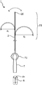
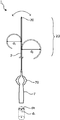
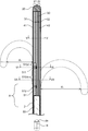
- 1 to 3 show a plan view of the catheter according to the embodiment of the present invention
- the dotted line shows the state when the distal portion of the catheter is curved toward one side and the other side of the leaf spring in the radial direction of the shaft.
- the dotted line in FIG. 2 shows the state when the distal portion of the catheter is further curved as compared with the case shown in FIG.
- the dotted line in FIG. 3 shows the state when the distal portion of the catheter is further curved as compared with the case shown in FIG.
- FIG. 4 shows a sectional view of the distal portion of the catheter shown in FIG.
- FIG. 8 shows a side view of the first wire and the second wire, the leaf spring, the support member, and the first coil arranged in the shaft lumen in the portion A of the distal portion of the catheter shown in FIG.
- FIG. 9 shows a side view of the first coil according to the embodiment of the present invention in a natural state
- FIG. 10 shows a side view of the first coil shown in FIG. 9 at the time of maximum compression.
- FIG. 11 shows a side view of the first coil according to another embodiment of the present invention in a natural state.
- FIG. 12 shows a longitudinal sectional view of the distal portion of the catheter according to another embodiment of the present invention, and the dotted line indicates that the distal portion of the catheter is curved toward one side and the other side of the leaf spring in the radial direction of the shaft. It shows the state of time.
- FIG. 13 shows a longitudinal sectional view of the distal portion of the catheter according to still another embodiment of the present invention, and the dotted line indicates that the distal portion of the catheter is curved toward one side and the other side of the leaf spring in the radial direction of the shaft. It shows the state when it was done.
- FIG. 14 shows a method for measuring rigidity.
- FIG. 15 represents another example of a VV cross section of the distal catheter shown in FIG.
- the proximal side refers to the user's hand side with respect to the extending direction of the shaft
- the distal side refers to the opposite side of the proximal side, that is, the treatment target side.
- the extending direction of the shaft is referred to as a longitudinal direction d L.
- the radial direction d R refers to the radial direction perpendicular to the extending direction of the shaft.
- the lower side of the figure is the proximal side
- the upper side of the figure is the distal side.
- a one side of the leaf spring left figure in the radial direction d R of the shaft, the other right side of the figure is of the leaf spring in the radial direction d R of the shaft It is on the direction side.
- the catheter 1 has a shaft 2 having a distal end and a proximal end and having a lumen extending in the longitudinal direction d L. It is preferable that the tip portion 20 is arranged at the distal end of the shaft 2, and it is preferable that the handle 7 is arranged at the proximal end of the shaft 2.
- the shaft 2 is inserted into the body from the distal end and delivered to the treatment site. Therefore, it is preferably flexible, and a metal or resin can be used as the material. Since it is inserted into the body, it is preferable to use a biocompatible material.
- a device for treatment such as an electrode and a sensor can be arranged on the surface of the shaft 2. By providing an electrode on the surface of the shaft 2, it can be used as an electrode catheter for measuring electrocardiographic potential or an ablation catheter for cauterizing tissue.
- the lumen of the shaft 2 may be a single lumen or may be partially composed of a plurality of lumens.
- the structure for curvature of the present invention is arranged in a single lumen.
- the curved portion may be a single lumen, and a plurality of lumens proximal to the lumen may be formed.
- the lumen may have a double structure.
- the length, outer diameter, thickness, etc. of the shaft in the longitudinal direction d L can be selected from an appropriate size for treatment.
- the tip portion 20 is arranged at the distal end of the shaft 2.
- the tip portion 20 may be a member different from the shaft 2 or may be the same member.
- the tip portion 20 may include a portion inserted into the lumen of the shaft 2 or a portion protruding distally from the distal end of the shaft. ..
- the tip portion 20 is formed by closing the opening of the distal end portion of the shaft 2 by heat fusion or the like of the distal end portion of the shaft 2. You may.
- the handle 7 is arranged on the proximal side of the shaft 2, and it is preferable that the proximal end of the shaft 2 is fixed to the inside of the handle 7.
- a conducting wire and an operating wire extending from the lumen of the shaft 2 are arranged inside the handle 7.
- the handle 7 may include a wire operating portion 70 so that the operating wire can be easily operated. By fixing the proximal end of the operating wire to the wire operating portion 70, the wire operating portion 70 can be operated to pull the wire or the like and bend the distal end of the catheter 1.
- the catheter 1 has a distal end and a proximal end within the lumen of the shaft 2, with the distal end being the distal end of the shaft 2, eg, the tip 20.
- the first wire 41 and the first wire 41 and the proximal end are located at the proximal end of the shaft 2, eg, the handle 7, and extend into the lumen of the shaft 2 (eg, extend from the tip 20 to the handle 7). It has two wires 42, a distal end and a proximal end, and in the longitudinal direction d L , the cavity of the shaft 2 is arranged, the first part 21 in which the first wire 41 is arranged, and the second wire 42 are arranged.
- leaf spring 30 arranged so as to be separated from the second part 22, a distal end and a proximal end , extending in the longitudinal direction d L , and the first wire 41 and the second wire 42 are It has an arranged cavity, a proximal end of the leaf spring 30 is fixed, and a support member 60 arranged proximal to the leaf spring 30 is arranged.
- the first wire 41 and the second wire 42 are operation wires for bending the distal shaft portion 2D of the catheter 1. It is preferred that the first wire 41 and the second wire 42 are arranged in the lumen of the shaft 2, with the distal end fixed to the tip 20 and the proximal end fixed to the handle 7.
- a metal wire rod such as stainless steel or a wire rod formed of a synthetic resin such as fluororesin can be used.
- the first wire 41 and the second wire 42 may each have one wire rod or may have a structure composed of a plurality of wire rods.
- the leaf spring 30 is a member that defines the bending direction of the catheter 1, and a first portion 21 in which the first wire 41 is arranged and a second wire 42 are arranged in the lumen of the shaft 2 in the longitudinal direction d L. It is arranged so as to separate the lumen of the shaft 2 from the second part 22 to be formed.
- the proximal end of the leaf spring 30 is fixed to the support member 60.
- the distal end of the leaf spring 30 is preferably fixed to the distal end of the shaft 2.
- the tip portion 20 is provided at the distal end of the shaft 2, it is preferably fixed to the tip portion 20.
- the distal end of the leaf spring 30 does not have to be fixed.
- the distal end or the proximal end of the leaf spring 30 may be fixed by not directly fixing the end portion but fixing the vicinity thereof.
- the method for fixing the distal end and the proximal end of the leaf spring 30 is not particularly limited, and examples thereof include brazing of solder and the like, welding, adhesion with an adhesive, connection by caulking, and the like. ..
- the tip portion 20 and the support member 60 are made of metal, they are preferably fixed by laser welding.
- the leaf spring 30 has a distal end and a proximal end, and has a shape extending in the longitudinal direction d L.
- the leaf spring 30 is preferably arranged along the longitudinal axis of the shaft 2.
- the lumen of the shaft 2 is partitioned by the leaf spring 30 into two parts, a first part 21 on one side including the longitudinal axis of the shaft 2 and a second part 22 on the other side.
- the first wire 41 is arranged in one first portion 21 of the lumen of the partitioned shaft 2, and the second wire 42 is arranged in the second portion 22 of the other.
- the surface of the leaf spring 30 on the side where the first wire 41 is arranged is referred to as the first surface 31, and the surface of the leaf spring 30 on the side where the second wire 42 is arranged is referred to as the second surface 32. It can be said that the first surface 31 of the leaf spring 30 is one surface and the second surface 32 is the other surface.
- the leaf spring 30 is a spring using a plate material, and examples of the material constituting the leaf spring 30 include metals such as stainless steel, titanium, carbon steel, nickel-titanium alloy, cobalt-chromium alloy, and tungsten alloy.
- examples of the material constituting the leaf spring 30 include synthetic resins such as aromatic polyetherketone resin (for example, PEEK), polycarbonate resin, and fiber reinforced resin.
- the leaf spring 30 may be made of synthetic rubber such as butadiene rubber, isoprene rubber, styrene butadiene rubber, ethylene propylene rubber, acrylic rubber, silicone rubber, or natural rubber. Above all, the material of the leaf spring 30 is preferably stainless steel.
- the support member 60 is arranged on the proximal side of the leaf spring 30 in the lumen of the shaft 2, and the first wire 41 and the second wire 42 are arranged in the lumen.
- the proximal end of the leaf spring 30 is fixed to the distal end of the support member 60.
- the proximal end of the support member 60 may extend to the proximal end of the shaft 2 or may be located in the middle of the shaft 2.
- the support member 60 may be switched to a different member, for example, a tube or the like in the middle of the shaft 2.
- the support member 60 may be a proxy tube having a tubular shape. If the support member 60 is a proxy tube, the proxy tube can accept the proximal end of the leaf spring 30 and a portion of the leaf spring 30 can be placed in the lumen of the proxy tube. Thereby, the fixing between the leaf spring 30 and the support member 60 can be strengthened.
- the support member 60 is preferably flexible like the shaft 2, and a metal or resin can be used as the material. Of these, a coil around which a metal wire is wound is preferable. Since the internal structure of the catheter 1 of the present invention is switched at the distal end of the support member 60, the change in hardness of the catheter 1 does not become large between the distal end and the proximal side of the support member 60. , The size, flexibility and material of the support member 60 are preferably selected.
- the catheter 1 has a lumen in which the first wire 41 is arranged, and includes a first coil 51 arranged distal to the distal end of the support member 60.
- the first coil 51 is arranged on the proximal end side of the leaf spring 30, and is fixed to the proximal end side of the leaf spring 30 at at least two places.
- the arrangement on the proximal end side of the leaf spring 30 means that it is arranged on the portion near the proximal end of the leaf spring, and the proximal end of the first coil 51 is adjacent to the distal end of the support member 60. Or it means that they are arranged in close proximity.
- the first coil 51 is a member that regulates the bending of the leaf spring 30 toward one side 31 side, when the first coil 51 is fixed to the distal side of the leaf spring 30, the leaf spring 30 is on one side. It becomes impossible to bend to the 31 side.
- the first coil 51 has a first fixing portion 511, which is a portion where the first coil 51 and the leaf spring 30 are fixed, a second fixing portion 512 located proximal to the first fixing portion, and a first fixing portion. It has an intermediate non-fixed portion 510 m which is located between the portion 511 and the second fixed portion 512 and is not fixed to the leaf spring 30.
- the first coil 51 can be made of a metal wire such as stainless steel or nickel-titanium alloy, or a synthetic resin wire such as aromatic polyetherketone resin (for example, PEEK) or polycarbonate resin.
- the cross-sectional shape of the wire forming the first coil 51 can be circular, quadrangular, or a combination thereof.
- the first coil 51 is preferably a metal coil made of stainless steel and using a wire having a circular cross section.
- the wire diameter, coil diameter, and length of the first coil 51 can be appropriately selected as needed.
- first coil 51 and the leaf spring 30 are fixed by welding, soldering, bonding, or pressure welding. Above all, fixing by welding is preferable. If it is fixed by welding, the first fixing portion 511 and the second fixing portion 512 can be formed without using a material such as solder or an adhesive.
- the fixing of the first coil 51 and the leaf spring 30 is the direct fixing of the first coil 51 and the leaf spring 30, the fixing by the proximal end of the first coil 51 in contact with the support member 60, or the first.
- the first coil 51 and the leaf spring 30 may be indirectly fixed by fixing the one coil 51 to the support member 60 by welding, soldering, bonding, or pressure welding.
- the second fixing portion 512 may be a fixing portion fixed by the proximal end of the first coil 51 being in contact with the support member 60, or the second fixing portion 512 may be the first coil 51.
- the first coil 51 and the leaf spring 30 may be indirectly fixed by being fixed to the support member 60 by welding, soldering, bonding, or pressure welding.
- the positions of the first fixing portion 511 and the second fixing portion 512 in the longitudinal direction d L are not particularly limited, and may be arranged anywhere on the surface of the first coil 51.
- the first fixing portion 511 may be arranged at the distal end of the first coil 51
- the second fixing portion 512 may be arranged at the proximal end of the first coil 51.
- a fixing portion may be further provided in addition to the first fixing portion 511 and the second fixing portion 512.
- the total number of fixed portions is two or more, and may have more than two fixed portions.
- the first coil 51 can be fixed to the leaf spring 30 so that the leaf spring 30 on the proximal side from the fixing portion on the most distal side does not bend toward the one side 31 side.
- the length of the fixed portion of the first coil 51 including the first fixed portion 511 and the second fixed portion 512 and the leaf spring 30 in the longitudinal direction d L can be appropriately set, but in the longitudinal direction d L of the fixed portion.
- the length is preferably short, and as shown in FIG. 8, it is preferably as long as, for example, about three wires forming a coil. If the length of the fixed portion in the longitudinal direction d L is long, the flexibility when the catheter 1 bends toward the other surface 32 may be lost.
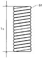
- the first coil 51 has a total length L 1 in a natural state and a total length L C 1 at the time of maximum compression.
- the ratio, L C1 / L 1 is 0.9 or more.
- the first coil 51 is preferably uncompressed as shown in FIG.
- the uncompressed coil is a tightly wound coil, that is, a coil that is not compressed in the longitudinal direction d L, and has a total length L 1 of the coil in the natural state and a total length L C 1 of the coil at the time of maximum compression.
- the ratio of L C1 / L 1 is 1, but when L C1 / L 1 is 0.9 or more and 0.95 or more, it is substantially uncompressed and is included in the uncompressed coil.
- L C1 / L 1 is preferably 0.95 or more.
- the distal shaft portion 2D can be curved to either one side or the other side, and each curved shape can be a different shape.
- the respective curved diameters can be different, and the degree of difference in the curved diameter can be strictly controlled.
- the first coil 51 is fixed to the leaf spring 30 at at least two points on the proximal side of the leaf spring 30, and the first coil 51 is an uncompressed coil, the first coil is the leaf spring 30. It cannot be curved in the non-side, that is, in the direction of one side 31. This is because since the uncompressed coil is fixed at two points, the first coil 51 cannot be compressed with respect to the curvature to one surface between the two points, and functions and behaves as a rigid tube. Therefore, in the leaf spring 30, only the portion between the portion fixed to the tip portion 20 and the fixed portion on the most distal side of the first coil 51 can be bent toward one side.
- the first coil 51 can be curved toward one side 31 side as well as the leaf spring 30. Further, if the first coil 51 is not an uncompressed coil, the coil can be extended with respect to one side and the other side, and can be curved toward one side. Therefore, the leaf spring 30 can be curved to one side 31 side in the range from the distal side to the proximal side regardless of whether the first coil 51 is fixed at two points with the leaf spring 30 or is incompressible. Will be.
- the second wire 42 arranged in the second portion 22 of the lumen of the shaft 2 of the catheter 1 is pulled.
- the leaf spring 30 is curved toward the other surface 32, and the distal shaft portion 2D of the catheter 1 is curved toward the other surface 32.
- the first coil 51 arranged on the one side 31 side of the leaf spring 30 is curved on the other side 32 side of the leaf spring 30 by increasing the distance between the coil strands of the non-fixed portion on the one side of the coil. Following it, it can be curved toward the other surface 32 side. Therefore, the leaf spring 30 can be bent toward the other surface 32 in all the portions from the portion fixed to the tip portion 20 to the distal end of the support member 60.
- the portion where the first coil 51 and the leaf spring 30 are fixed is preferably located on the surface of the first coil 51 facing the one surface 31 of the leaf spring 30. As a result, the bending of the first coil 51 toward the leaf spring 30 side, that is, the other surface 32 side is not hindered.
- the intermediate non-fixed portion 510 m which is a portion without a fixed portion between the first fixed portion 511 and the second fixed portion 512 of the first coil 51, has a length in the natural state of the longitudinal direction d L of the first coil 51. It is preferably 50% or more of the total length L 1 in the natural state.
- the length of the longest intermediate non-fixed portion 510 m in the longitudinal direction d L in the natural state may be 50% or more of the total length L 1 in the natural state of the first coil 51. preferable.
- the length of the longest intermediate non-fixed portion 510 m of the first coil 51 is such that the length in the natural state of the longitudinal direction d L is 30% or more of the total length L 1 in the natural state of the first coil 51. It may be 20% or more. Even in such a range, it is possible to prevent the bending of the first coil 51 toward the one side 31 side and not to hinder the bending toward the other surface 32 side.
- the length of the longest intermediate non-fixed portion 510 m in the longitudinal state d L in the natural state is long. Even if the value is smaller than 50% of the total length L 1 of the first coil 51 in the natural state, it is possible to effectively prevent the first coil 51 from bending toward one surface 31 side.
- the curved shape of the curved portion on the distal side of the catheter 1 can be controlled.
- the curvature toward the one side 31 side is formed by the portion between the fixing portion of the distal end portion of the shaft 2 of the first wire 41 and the fixing portion on the most distal side of the first coil 51, and is formed on the other side 32 side. This is because the curvature to is formed by the portion of the second wire 42 from the fixation point at the distal end of the shaft 2 to the distal end of the support member 60.
- the first coil 51 does not have a fixing portion for fixing the first coil 51 and the leaf spring 30 between the distal end of the first coil 51 and the first fixing portion 511.
- the bendable portion distal to the first coil 51 It is possible to prevent the shape of the curvature from being extremely changed between the first coil 51 and the portion that does not bend toward the one surface 31 side proximal to the fixed portion on the most distal side. For example, if the most distal fixation portion of the first coil 51 is at the distal end of the first coil 51, the catheter 1 may break at the distal end of the first coil 51.
- the catheter 1 may further include a second coil 52.
- the second coil 52 has a lumen in which the first wire 41 is arranged, and is a first portion 21 partitioned by a leaf spring 30 in the lumen of the shaft 2, and is distal to the first coil 51. Placed on the side.
- the second coil 52 may be in contact with any portion such as the leaf spring 30 in the lumen of the shaft 2, but it is preferable that the second coil 52 is not fixed to any portion.
- the catheter 1 may further include a third coil 53.
- the third coil 53 has a lumen in which the second wire 42 is arranged, and is arranged in the second portion 22 partitioned by the leaf spring 30 in the lumen of the shaft 2.
- the third coil 53 may be in contact with any portion such as the leaf spring 30 in the lumen of the shaft 2, but it is preferable that the third coil 53 is not fixed to any portion.
- the second coil 52 has a total length L 2 in the natural state and a total length L C 2 at the time of maximum compression, as in FIGS. 9 and 10 for the first coil 51.
- L C2 / L 2 is more preferably less than 0.9 and more preferably less than L C1 / L 1 .
- the third coil 53 has a total length L 3 in a natural state and a total length L C 3 at the time of maximum compression.
- L C3 / L 3 is more preferably less than 0.9 and more preferably less than L C1 / L 1 .
- the ratio L C1 / L 1 of the total length L 1 in the natural state of the first coil 51 to the total length L C 1 at the time of maximum compression is the ratio L C2 / L 2 and L C3 / L of the second coil 52 and the third coil 53.
- the first coil 51 is the same as or more easily deformed than the second coil 52 and the third coil 53, and it becomes difficult to control the curved shape of the catheter 1.
- the lengths of the first coil 51, the second coil 52, and the third coil 53 can be appropriately selected according to the shape of the required curvature in the catheter 1.
- the first wire 41 and the second wire 42 may be partially exposed between the tip portion 20 and the support member 60 as shown in FIG. 12, and the first coil 51 may be partially exposed as shown in FIG.
- the second coil 52, and the third coil 53 may be all arranged in the lumen.
- the first coil 51 and the third coil 53 can be arranged so as to be in contact with the support member 60.
- the first coil 51 and the third coil 53 may be arranged with a slight distance from the support member 60, and the first wire 41 and the second wire 42 may be exposed. This also applies to the relationship between the tip portion 20, the second coil 52, and the third coil 53.
- the first coil 51 and the second coil 52 may be in contact with each other or may have a gap.
- the first coil 51, the second coil 52, and the third coil 53 are made of spirally wound coil wires.
- the pitch intervals of the first coil 51, the second coil 52, and the third coil 53 can be appropriately set.
- the pitch interval of the coils is the interval between the adjacent coil wires forming the coil and the center points of the coil wires.
- Pitch interval can be measured as the pitch spacing P 1 of the first coil 51 shown in FIG.
- the pitch interval is larger than the thickness of the coil streaks, there is a gap between the coil streaks and the coil can be compressed.
- L C / L approximates the coil wire diameter / pitch interval.
- L C1 / L 1 of the first coil 51 is 0.9 or more
- the coil wire diameter / pitch interval of the first coil 51 is 0.9 or more.
- the coil wire diameter and the coil diameter of the second coil 52 and the third coil 53 are appropriately selected according to the shape of the required curvature in the catheter 1. Can be done.
- metal or resin can be used as mentioned as the material of the first coil.
- the total length L of the coil in the natural state and the total length L C of the coil at the time of maximum compression can be controlled not only by the pitch interval but also by the coil wire diameter, coil diameter, material and the like of the coil.
- the pitch interval P 1 of the first coil 51 is preferably smaller than the pitch interval of the second coil 52 or the pitch interval of the third coil 53.
- the pitch interval By setting the pitch interval in this way, the total length L of the coil in the natural state and the total length L C of the coil at the time of maximum compression are appropriately adjusted, and L C2 / L 2 and L C3 / L 3 are L C1 /. It can be smaller than L 1.
- the pitch interval P 1 of the first coil 51 is preferably smaller than the pitch interval of the second coil 52.
- the coil wire diameter and the coil diameter of the first coil 51 are the same as the coil wire diameter and the coil diameter of the second coil 52.
- the coil wire diameter is the diameter of the wire forming the coil, and the coil diameter is the diameter of the coil.
- the pitch interval of the second coil 52 may be the same as or different from the pitch interval of the third coil 53.
- the pitch spacing of the second coil 52 and the pitch spacing of the third coil 53 may be such that the coil is not completely compressed when it is bent to the maximum. Since the first coil 51 is present, the bending diameter of the curvature toward one surface 31 side of the catheter 1 is smaller than the bending diameter of the curvature toward the other surface 32 side, and the second coil 52 is larger than the third coil 53. It gets shorter. Since the second coil 52 is shorter than the third coil 53, the second coil 52 is more likely to be completely compressed, and from this point, it is better to set the pitch interval of the second coil 52 to be wider.
- the coil wire diameter and coil diameter of the second coil 52 may be the same as or different from the coil wire diameter and coil diameter of the third coil 53, but are preferably the same. Since the pitch interval of the second coil 52 is different from the pitch interval of the third coil 53, the shape of the curvature of the catheter 1 toward the one side 31 side and the shape of the curvature toward the other surface 32 side can be made different. ..
- the coil wire diameter and coil diameter of the first coil 51 may be the same as those of the second coil 52 and the third coil 53, or may be different.
- the bending rigidity of the first coil 51 is larger than the bending rigidity of the second coil 52, and the difference between the bending rigidity of the first coil 51 and the bending rigidity of the second coil 52 is preferably 50% or less.
- the shape of the curvature when the shaft distal portion 2D is curved toward the one side 31 side of the leaf spring 30 can be made smooth.
- the method for adjusting the rigidity include selection of the type and amount of wire rod constituting each coil, adjustment of the inner and outer diameters of each coil, adjustment of the pitch interval of each coil, and the like.
- Rigidity can be obtained by a three-point bending test as shown in FIG.
- the three-point bending test was performed according to JIS K7171.
- the rigidity measurement sample 603 was placed on the two fulcrums 602 arranged on the support base 601 at a distance of the fulcrum distance D, and the indenter 604 arranged at the center of the fulcrum distance D was moved by a certain distance in the vertical direction.
- the load F at the time is measured, and this load F is taken as the rigidity of the rigidity measurement sample 603.
- the catheter 1 having the above configuration has a curved shape and a distal shaft portion when the distal shaft portion 2D is curved toward one side 31 of the leaf spring 30 by the first coil 51.
- the curved shape when the 2D is curved toward the other surface 32 of the leaf spring 30 can be different.
- the bending diameter d 1 when the shaft distal portion 2D is curved toward the one side 31 side of the leaf spring 30, and the bending diameter d when the shaft distal portion 2D is curved toward the other surface 32 side of the leaf spring 30. Can be smaller than 2.
- the curvature diameter d 1 is the diameter of the circumscribed circle on the outer surface of the shaft distal portion 2D curved toward one surface 31 side of the leaf spring 30 on the first wire 41 side, and the curvature of the shaft distal portion 2D. Is the diameter of the circle if is part of the arc.
- the bending diameter d 2 is the diameter of the circumscribed circle on the outer surface of the shaft distal portion 2D curved toward the other surface 32 side of the leaf spring 30 on the second wire 42 side, and the curvature of the shaft distal portion 2D is formed. If it is part of an arc, it is the diameter of the circle.
- the curved circumscribed circle does not necessarily have to be a perfect circle.
- the curved shape may be a shape on an circumscribed circle or a combination of straight lines and curves instead of an arc.
- the shape of the curvature on the one side 31 side and the shape of the curvature on the other side 32 side can be different depending on the first coil 51.
- the catheter 1 has a lumen and further has a protective tube 80 disposed in the lumen of the shaft 2, with a leaf spring 30 and a first coil in the lumen of the protective tube 80. It is preferable that the 51, the second coil 52, and the third coil 53 are arranged. A material similar to the material forming the shaft 2 can be used for forming the protective tube 80.
- the protective tube 80 can protect the leaf spring 30, the first coil 51, the second coil 52, the third coil 53, and the first wire 41 and the second wire 42.
- the protective tube 80 may be in contact with any portion, but is preferably fixed to the support member 60. Thereby, the protective tube 80 can prevent the coil from moving in the shaft 2.
Landscapes
- Health & Medical Sciences (AREA)
- Life Sciences & Earth Sciences (AREA)
- Engineering & Computer Science (AREA)
- Anesthesiology (AREA)
- Biophysics (AREA)
- Pulmonology (AREA)
- Biomedical Technology (AREA)
- Heart & Thoracic Surgery (AREA)
- Hematology (AREA)
- Animal Behavior & Ethology (AREA)
- General Health & Medical Sciences (AREA)
- Public Health (AREA)
- Veterinary Medicine (AREA)
- Mechanical Engineering (AREA)
- Media Introduction/Drainage Providing Device (AREA)
Abstract
カテーテル遠位部が一方側、他方側の湾曲形状が異なる非対称湾曲タイプのカテーテルを提供することを目的とする。 シャフトと、第1ワイヤ及び第2ワイヤと、シャフトの内腔を第1ワイヤが配置される第1部と第2ワイヤが配置される第2部に分離するように配置されている板バネと、支持部材と、第1ワイヤが配置されている内腔を有する第1コイルとを有しており、第1コイルは板バネの近位端側に少なくとも2箇所で固定されており、第1コイルは自然状態における全長L1と最大圧縮時の全長LC1とを有し、その比LC1/L1は0.9以上である。
Description
本発明は、先端部が湾曲可能なカテーテルに関する。
心臓内の電位を測定したりペーシングを行ったりするために、遠位部に複数の電極を有する電極カテーテルが用いられている。このような電極付きのカテーテルの中には、心臓内の所望の部位にカテーテル遠位部を容易に配置することができるように、ハンドル操作によって遠位部が湾曲可能なものがある。このようなカテーテルは、一般的に、カテーテルの先端内部に固定されたプルワイヤを引くことでカテーテル遠位部を湾曲させることができる。さらに、カテーテルをカテーテルの長手方向を中心に一方側、他方側の両側に湾曲させるために、2本のプルワイヤを備えたカテーテルが提案されている。
例えば特許文献1には、カテーテルチューブの内腔に操作ワイヤが配置された複数の操作用チューブを備え、操作用チューブが複数の部分チューブに分割されていることにより、カテーテルの先端部分が途中で折れ曲がりのない滑らかな湾曲形状に変形することができる先端偏向操作可能カテーテルが開示されている。また、カテーテルの先端部を湾曲させても、先端電極や、カテーテルの先端内部に配置された板バネやプルワイヤの脱落を防止できる先端偏向操作可能カテーテルや(特許文献2、3)、一方側と他方側の湾曲の形状が異なるカテーテルも提案されている(特許文献4、5)。
心臓の大きさや目的に合わせて最適な部位へカテーテル遠位部を送達するためには、カテーテル遠位部が一方側、他方側のどちら側にも湾曲できるだけでなく、さらにそれぞれの湾曲径が異なる非対称湾曲タイプのカテーテルとすることが求められる。また、湾曲の非対称度合いを高めることで、カテーテル遠位部を所望の部位へ容易に送達することが可能となる。しかし、特許文献4、5のような構成では、湾曲径の非対称度合いのより高いカテーテルとすることは困難であった。
本発明は、上記事情に鑑みてなされたものであり、その目的は、カテーテル遠位部が一方側、他方側のどちら側にも湾曲可能であり、それぞれの湾曲形状が異なる非対称湾曲タイプのカテーテルを提供することにある。
上記課題を解決することのできたカテーテルは、遠位端と近位端とを有し、長手方向に延在する内腔を有するシャフトと;遠位端と近位端とを有し、上記遠位端がシャフトの遠位端部に固定され、上記近位端がシャフトの近位端部に配置され、シャフトの内腔に延在する第1ワイヤ及び第2ワイヤと;長手方向においてシャフトの内腔を、第1ワイヤが配置される第1部と、第2ワイヤが配置される第2部に分離するようにシャフトの内腔に配置されている板バネと;長手方向に延在し、第1ワイヤ及び第2ワイヤが配置されている内腔を有し、板バネの近位端が固定されており、板バネより近位側に配置されている支持部材と;第1ワイヤが配置されている内腔を有し、支持部材の遠位端より遠位側であって第1部内に配置されている第1コイルであって、第1コイルは、板バネの近位端側に少なくとも2箇所で固定されており、第1コイルと板バネが固定されている部分である第1固定部と、第1固定部より近位側に位置し第1コイルと板バネが固定されている部分である第2固定部と、第1固定部と第2固定部との間に位置し板バネに固定されていない部分である中間非固定部とを有しており、上記第1コイルは、自然状態における全長L1と最大圧縮時の全長LC1とを有し、その比であるLC1/L1は0.9以上である上記第1コイルとを有することを特徴とするものである。
支持部材はプロキシチューブであることが好ましい。
第1コイルは、非圧縮であることが好ましい。
第1コイルと板バネとが固定されている部分は、第1コイルの板バネの一方面に面する面に位置することが好ましい。
第1コイルの非固定部であって、長手方向の長さが最も長い非固定部は、長手方向の自然状態における長さが、第1コイルの自然状態における全長L1の50%以上であることが好ましい。
第1コイルは、第1コイルの遠位端と第1固定部との間に、第1コイルと板バネとを固定する固定部を有していない遠位側非固定部をさらに有することが好ましい。
さらに、第2コイルを備え、第2コイルは、第1ワイヤが配置されている内腔を有し、第1部内であって第1コイルよりも遠位側に配置されていることが好ましい。
この場合、第2コイルは、自然状態における全長L2と最大圧縮時の全長LC2とを有し、LC2/L2は0.9よりも小さいことが好ましい。
第1コイルの曲げ剛性は、第2コイルの曲げ剛性よりも大きく、第1コイルの曲げ剛性と第2コイルの曲げ剛性との差は50%以下であることが好ましい。
第1コイルはらせん状に巻かれた第1コイルワイヤを含み、第2コイルはらせん状に巻かれた第2コイルワイヤを含み、第1コイルのピッチ間隔は、第2コイルのピッチ間隔よりも小さいことが好ましい。
第1コイルのコイルワイヤ径及びコイル径は、第2コイルのコイルワイヤ径及びコイル径と同じであることが好ましい。
さらに、第3コイルを備え、第3コイルは、第2ワイヤが配置されている内腔を有し、第2部に配置されていることが好ましい。
第3コイルは、自然状態における全長L3と最大圧縮時の全長LC3とを有し、LC3/L3は0.9よりも小さいことが好ましい。
第2コイルを備え、第2コイルは、第1ワイヤが配置されている内腔を有し、第1部の第1コイルよりも遠位側に配置されており;第3コイルを備え、第3コイルは、第2ワイヤが配置されている内腔を有し、第2部に配置されており;内腔を有しシャフト内腔内に配置される保護チューブをさらに有しており、保護チューブは、内腔に板バネ、第1コイル、第2コイル、及び第3コイルが配置されていることが好ましい。
第1コイルは、第1固定部及び第2固定部が、溶接、はんだ、接着、又は圧接により固定されていることが好ましい。
本発明によれば、カテーテル遠位部が一方側、他方側のどちら側にも湾曲可能であり、それぞれの湾曲形状が異なる非対称湾曲タイプのカテーテルを提供することができるため、カテーテル遠位部を所望の位置へ容易に送達することができる。
以下、実施の形態に基づき本発明を説明するが、本発明はもとより下記実施の形態によって制限を受けるものではなく、前・後記の趣旨に適合し得る範囲で適当に変更を加えて実施することも勿論可能であり、それらはいずれも本発明の技術的範囲に包含される。なお、各図面において、便宜上、ハッチングや部材符号等を省略する場合もあるが、かかる場合、明細書や他の図面を参照するものとする。また、図面における種々部材の寸法は、本発明の特徴の理解に資することを優先しているため、実際の寸法とは異なる場合がある。
本発明のカテーテルは、遠位端と近位端とを有し、長手方向に延在する内腔を有するシャフトと;遠位端と近位端とを有し、上記遠位端がシャフトの遠位端部に固定され、上記近位端がシャフトの近位端部に配置され、シャフトの内腔に延在する第1ワイヤ及び第2ワイヤと;長手方向においてシャフトの内腔を、第1ワイヤが配置される第1部と、第2ワイヤが配置される第2部に分離するようにシャフトの内腔に配置されている板バネと;長手方向に延在し、第1ワイヤ及び第2ワイヤが配置されている内腔を有し、板バネの近位端が固定されており、板バネより近位側に配置されている支持部材と;第1ワイヤが配置されている内腔を有し、支持部材の遠位端より遠位側であって第1部内に配置されている第1コイルであって、第1コイルは、板バネの近位端側に少なくとも2箇所で固定されており、第1コイルと板バネが固定されている部分である第1固定部と、第1固定部より近位側に位置し第1コイルと板バネが固定されている部分である第2固定部と、第1固定部と第2固定部との間に位置し板バネに固定されていない部分である中間非固定部とを有しており、上記第1コイルは、自然状態における全長L1と最大圧縮時の全長LC1とを有し、その比であるLC1/L1は0.9以上である上記第1コイルとを有する。
上記構成を有することにより、本発明のカテーテルは、シャフトの半径方向において板バネの一方面側及び他方面側の両方にカテーテル遠位部が湾曲可能であり、板バネの一方面側に湾曲したときの湾曲形状と板バネの他方面側に湾曲したときの湾曲形状とが異なる非対称湾曲タイプのカテーテルとすることができる。このため、本発明のカテーテルは、カテーテル遠位部を血管や心臓の所望の位置へ容易に送達することが可能となる。湾曲形状が異なるとは、一方側に湾曲したときの形状と他方側に湾曲したときの形状が異なることをいい、湾曲形状が沿う円のサイズ、言い換えれば半径が異なることを含む。本発明によれば、一方面側の湾曲形状と、他方面側の湾曲形状との間のカーブ形状の差、特にサイズの差をより大きくすることができるため、血管の種々の形状のカーブに対応することができる。
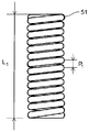
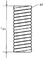
以下では、図1~図15を参照して、本発明の実施形態に係るカテーテルについて説明する。図1~図3は本発明の一実施形態にかかるカテーテルの平面図を表し、点線はシャフトの半径方向において板バネの一方面側及び他方面側にカテーテル遠位部が湾曲したときの様子を表している。図2の点線は図1に示した場合よりもカテーテル遠位部がさらに湾曲したときの様子を表している。図3の点線は図2に示した場合よりもカテーテル遠位部がさらに湾曲したときの様子を表している。図4は図2に示したカテーテルの遠位部の長手方向の断面図を表し、点線はシャフトの半径方向において板バネの一方面側及び他方面側にカテーテル遠位部が湾曲したときの様子を表している。図5~図7は図4に示したカテーテル遠位部のV-V断面図、VI-VI断面図、及びVII-VII断面図をそれぞれ表す。図8は図4に示したカテーテル遠位部の部分Aにおける、シャフト内腔に配置されている第1ワイヤ及び第2ワイヤ、板バネ、支持部材、及び第1コイルの側面図を表す。図9は本発明の一実施形態に係る第1コイルの自然状態における側面図を表し、図10は図9に示した第1コイルの最大圧縮時の側面図を表す。図11は本発明の他の実施形態に係る第1コイルの自然状態における側面図を表す。図12は本発明の他の実施形態に係るカテーテル遠位部の長手方向の断面図を表し、点線はシャフトの半径方向において板バネの一方面側及び他方面側にカテーテル遠位部が湾曲したときの様子を表している。図13は本発明のさらに他の実施形態に係るカテーテル遠位部の長手方向の断面図を表し、点線はシャフトの半径方向において板バネの一方面側及び他方面側にカテーテル遠位部が湾曲したときの様子を表している。図14は剛性の測定方法を表す。図15は図4に示したカテーテル遠位部のV-V断面図の別の例を表す。
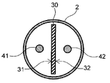
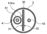
本発明において、近位側とはシャフトの延在方向に対して使用者の手元側を指し、遠位側とは近位側の反対側、すなわち処置対象者側を指す。また、シャフトの延在方向を長手方向dLと称する。半径方向dRとはシャフトの延在方向に垂直な半径方向を指す。図1~4、8、12、及び13において、図の下側が近位側であり、図の上側が遠位側である。また、図1~4、8、12、及び13において、図の左側がシャフトの半径方向dRにおける板バネの一方面側であり、図の右側がシャフトの半径方向dRにおける板バネの他方面側である。
図1~図3に示すように、カテーテル1は、遠位端と近位端とを有し、長手方向dLに延在する内腔を有するシャフト2を有している。シャフト2の遠位端には先端部20が配置されていることが好ましく、シャフト2の近位端部にはハンドル7が配置されていることが好ましい。
シャフト2は、遠位端から体内へ挿入され、治療部位まで送達される。このため可撓性があることが好ましく、材料として金属や樹脂を用いることができる。体内に挿入されるため、生体適合性のある材料を用いることが好ましい。シャフト2の表面には、電極やセンサなど、治療のための装置を配置することができる。シャフト2の表面に電極を備えることにより、心電位を測定する電極カテーテルや、組織を焼灼するアブレーションカテーテルとして用いることができる。
シャフト2の内腔には、カテーテルを湾曲させるための内部構造や、例えばセンサや導線など、治療のための装置やその内部構造を配置することができる。シャフト2の内腔は、単一の内腔でもよく、部分的に複数の内腔があってもよい。本発明の湾曲のための構造は、単一の内腔に配置される。例えば、カテーテル1のシャフト遠位部2Dを湾曲させるために、湾曲させる部分を単一の内腔として、それより近位側の内腔を複数とすることができる。内腔は二重構造であってもよい。シャフトの長手方向dLの長さ、外径、厚み等は治療のために適切なサイズを選択することができる。
シャフト2の遠位端には、先端部20が配置されることが好ましい。先端部20は、シャフト2とは別の部材であってもよいし、同じ部材であってもよい。先端部20がシャフト2とは別の部材である場合、先端部20は、シャフト2の内腔に挿入される部分やシャフトの遠位端より遠位側に突出する部分を備えていてもよい。先端部20がシャフト2と同じ部材である場合、シャフト2の遠位端部が熱融着等されることによってシャフト2の遠位端の開口が塞がれることにより、先端部20が形成されてもよい。
シャフト2の近位側にハンドル7が配置されることが好ましく、シャフト2の近位端は、ハンドル7の内部に固定されていることが好ましい。ハンドル7内には、シャフト2の内腔から延びる導線や操作ワイヤが配置される。操作ワイヤを操作しやすいように、ハンドル7がワイヤ操作部70を含んでいてもよい。操作ワイヤの近位端をワイヤ操作部70に固定することによって、ワイヤ操作部70を操作してワイヤを牽引等し、カテーテル1の遠位端を湾曲させることができる。
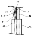
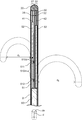
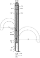
図4~図7に示すように、カテーテル1は、シャフト2の内腔内に、遠位端と近位端とを有し、遠位端がシャフト2の遠位端部、例えば先端部20に固定され、近位端がシャフト2の近位端部、例えばハンドル7に配置され、シャフト2の内腔に延在(例えば先端部20からハンドル7まで延在)する第1ワイヤ41及び第2ワイヤ42と、遠位端と近位端とを有し、長手方向dLにおいてシャフト2の内腔を、第1ワイヤ41が配置される第1部21と、第2ワイヤ42が配置される第2部22に分離するように配置されている板バネ30と、遠位端と近位端とを有し、長手方向dLに延在し、第1ワイヤ41及び第2ワイヤ42が配置されている内腔を有し、板バネ30の近位端が固定されており、板バネ30より近位側に配置されている支持部材60と、が配置されている。
第1ワイヤ41及び第2ワイヤ42は、カテーテル1のシャフト遠位部2Dを湾曲操作するための操作ワイヤである。第1ワイヤ41及び第2ワイヤ42は、シャフト2の内腔に配置されており、遠位端は先端部20に固定され、近位端はハンドル7に固定されていることが好ましい。第1ワイヤ41及び第2ワイヤ42としては、ステンレス鋼等の金属線材や、フッ素樹脂等の合成樹脂から形成された線材を用いることができる。第1ワイヤ41及び第2ワイヤ42は、それぞれ1本の線材であってもよく、複数の線材からなる構造を有していてもよい。
板バネ30は、カテーテル1の湾曲方向を規定する部材であり、シャフト2の内腔に、長手方向dLにおいて、第1ワイヤ41が配置される第1部21と、第2ワイヤ42が配置される第2部22とにシャフト2の内腔を分離するように配置されている。板バネ30の近位端は支持部材60に固定される。板バネ30の遠位端はシャフト2の遠位端部に固定されていることが好ましい。シャフト2の遠位端に先端部20を設けた場合には、先端部20に固定されることが好ましい。板バネ30の遠位端は固定されていなくてもよい。板バネ30の遠位端や近位端の固定は、端部が直接固定されておらず、その付近が固定されることにより、固定されていてもよい。板バネ30の遠位端及び近位端を固定する方法としては、特に限定されるものではないが、例えば、はんだ等のろう付け、溶接、接着剤による接着、かしめ等による接続等が挙げられる。先端部20や支持部材60が金属である場合、レーザー溶接により固定されていることが好ましい。
板バネ30は、遠位端と近位端を有し、長手方向dLに延在する形状である。板バネ30は、シャフト2の長手軸に沿って配置されることが好ましい。これにより、板バネ30によって、シャフト2の内腔がシャフト2の長手軸を含む一方側の第1部21と他方側の第2部22との2つに仕切られる。仕切られたシャフト2の内腔の一方の第1部21に第1ワイヤ41、他方の第2部22に第2ワイヤ42が配置される。第1ワイヤ41が配置される側の板バネ30の面を第1面31、第2ワイヤ42が配置される側の板バネ30の面を第2面32とする。板バネ30の第1面31は一方面、第2面32は他方面ということができる。
板バネ30は板材を用いたバネであり、板バネ30を構成する材料は、ステンレス鋼、チタン、炭素鋼、ニッケルチタン合金、コバルトクロム合金、タングステン合金等の金属が挙げられる。あるいは、板バネ30を構成する材料は、芳香族ポリエーテルケトン樹脂(例えば、PEEK)、ポリカーボネート樹脂や、繊維強化樹脂等の合成樹脂を挙げることができる。またあるいは、板バネ30は、ブタジエンゴム、イソプレンゴム、スチレンブタジエンゴム、エチレンプロピレンゴム、アクリルゴム、シリコーンゴム等の合成ゴムや天然ゴムで構成されていてもよい。中でも、板バネ30の材料はステンレス鋼であることが好ましい。
支持部材60は、シャフト2の内腔において板バネ30の近位側に配置され、その内腔には第1ワイヤ41と第2ワイヤ42が配置される。支持部材60の遠位端には板バネ30の近位端が固定されている。支持部材60の近位端は、シャフト2の近位端まで伸びていてもよく、シャフトの2の途中に配置されていてもよい。支持部材60は、シャフト2の途中で異なる部材、例えばチューブ等に切り替わっていてもよい。
支持部材60は、筒状の形状を有するプロキシチューブであってもよい。支持部材60がプロキシチューブであれば、プロキシチューブが板バネ30の近位端を受け入れ、板バネ30の一部がプロキシチューブの内腔に配置されることができる。これにより、板バネ30と支持部材60との固定を強固にすることができる。
支持部材60は、シャフト2と同様に可撓性があることが好ましく、材料として金属や樹脂を用いることができる。なかでも金属ワイヤが巻き回されたコイルであることが好ましい。本発明のカテーテル1は、支持部材60の遠位端で内部構造が切り替わるので、支持部材60の遠位端より遠位側と近位側とでカテーテル1の硬さの変化が大きくならないように、支持部材60のサイズ、可撓性、材料を選択することが好ましい。
本発明のカテーテル1は、板バネ30が、支持部材60の遠位端から露出している部分から、板バネ30がシャフト2の遠位端部、例えば先端部20に固定されるまでの区間において、湾曲することができる。したがって、カテーテル1の湾曲部の長さは、板バネ30の長さ、先端部20や支持部材60と板バネ30とを固定する位置によって適宜設定することができる。支持部材60は、板バネ30の湾曲に伴って簡単に変形しないことが好ましい。
図4に示すように、カテーテル1は、第1ワイヤ41が配置されている内腔を有し、支持部材60の遠位端より遠位側に配置されている第1コイル51を備える。第1コイル51は、板バネ30の近位端側に配置され、板バネ30の近位端側に少なくとも2箇所で固定されている。板バネ30の近位端側に配置とは、板バネの近位端寄りの部分に配置されていることをいい、第1コイル51の近位端が、支持部材60の遠位端に隣接又は近接して配置されていることをいう。第1コイル51は、板バネ30の一方面31側への湾曲を規制する部材であるので、第1コイル51が板バネ30の遠位側に固定されていると、板バネ30が一方面31側へ湾曲できない状態になる。第1コイル51は、第1コイル51と板バネ30が固定されている部分である第1固定部511と、第1固定部より近位側に位置する第2固定部512と、第1固定部511と第2固定部512との間に位置し板バネ30に固定されていない部分である中間非固定部510mとを有する。
第1コイル51は、ステンレス鋼、ニッケルチタン合金等の金属ワイヤや、芳香族ポリエーテルケトン樹脂(例えば、PEEK)、ポリカーボネート樹脂等の合成樹脂ワイヤで構成することができる。第1コイル51を形成するワイヤの断面形状は、円形、四角形又はそれらの組合せとすることができる。中でも、第1コイル51は、ステンレス鋼で断面が円形のワイヤを用いた金属コイルであることが好ましい。第1コイル51のワイヤ径、コイル径、長さは必要に応じて適宜選択することができる。
第1コイル51と板バネ30とは、溶接、はんだ、接着、又は圧接により固定されていることが好ましい。中でも、溶接による固定が好ましい。溶接により固定されていれば、はんだや接着剤等の材料を用いずに、第1固定部511及び第2固定部512を形成することができる。
第1コイル51と板バネ30との固定は、第1コイル51と板バネ30との直接の固定、第1コイル51の近位端が支持部材60に接していることによる固定、又は、第1コイル51が支持部材60に溶接、はんだ、接着、又は圧接により固定されていることによって、第1コイル51と板バネ30とが間接的に固定されている状態でもよい。第2固定部512が、第1コイル51の近位端が支持部材60に接していることにより固定された固定部であってもよく、又は、第2固定部512が、第1コイル51が支持部材60に溶接、はんだ、接着、又は圧接により固定されていることによって、第1コイル51と板バネ30とが間接的に固定されている状態であってもよい。
第1固定部511及び第2固定部512の長手方向dLにおける位置は特に限定されず、第1コイル51の表面のどこに配置されていてもよい。例えば、第1固定部511は第1コイル51の遠位端に配置されていてもよく、第2固定部512は第1コイル51の近位端に配置されていてもよい。また、図示していないが、第1固定部511及び第2固定部512以外にさらに固定部を有していてもよい。固定部の総数は2個以上であり、2個より多くの固定部を有していてもよい。少なくとも2個の固定部を設けることにより、第1コイル51を板バネ30に、最も遠位側の固定部から近位側の板バネ30が一方面31側へ湾曲しないように固定できる。シャフト2の第1コイル51が配置されている部分とそれ以外の部分との剛性の差が大きくなり過ぎないようにするために、固定部を2個とすることが好ましい。
第1固定部511及び第2固定部512を含む第1コイル51と板バネ30の固定部の長手方向dLにおける長さは、適宜設定することができるが、固定部の長手方向dLにおける長さは短い方が好ましく、図8に示すように、例えば、コイルを形成するワイヤ3本分くらいの長さであることが好ましい。固定部の長手方向dLの長さが長いと、カテーテル1が他方面32側へ湾曲する際の柔軟性が失われるおそれがある。
図9~図10に示すように、第1コイル51は、自然状態における全長L1と最大圧縮時の全長LC1とを有する。その比であるLC1/L1は0.9以上である。また、第1コイル51は、図11に示すように非圧縮であることが好ましい。ここで、本発明において、非圧縮なコイルとは、密巻コイル、すなわち長手方向dLに圧縮されないコイルであって、自然状態におけるコイルの全長L1と最大圧縮時のコイルの全長LC1との比LC1/L1が1のものであるが、LC1/L1が0.9以上、0.95以上の場合も実質的に非圧縮であり、非圧縮なコイルに含まれる。第1コイル51の非圧縮性を高くするためには、LC1/L1は、0.95以上であることが好ましい。
本発明の構成とすることにより、カテーテル1は、シャフト遠位部2Dが一方側、他方側のどちら側にも湾曲可能であり、それぞれの湾曲形状を異なった形状とすることができる。特に、それぞれの湾曲径が異なるものとすることができ、さらに、湾曲径の異なり具合を厳密に制御することができる。シャフト2の内腔の第1部21に配置されている第1ワイヤ41、言い換えると、板バネ30の一方面31側に配置されている第1ワイヤ41を牽引した場合、板バネ30は、一方面31側へ湾曲し、それにともないカテーテル1のシャフト遠位部2Dが一方面31側へ湾曲する。板バネ30の近位側に第1コイル51が、少なくとも2点で板バネ30と固定されており、かつ第1コイル51が非圧縮なコイルであるため、第1コイルは、板バネ30のない側、つまり一方面31方向へ湾曲することができない。非圧縮なコイルが2点で固定されているため、その2点間では、一方面への湾曲に対し第1コイル51は圧縮することができず、剛直なチューブとして機能し振舞うためである。このため、板バネ30は、先端部20に固定された部分から、第1コイル51の最も遠位側の固定部までの間の部分だけが、一方面側へ湾曲可能となる。
もし、板バネ30と第1コイル51とが1点でしか固定されていないとすると、第1コイル51は、板バネ30の湾曲とともに一方面31側へも湾曲することができる。また、もし第1コイル51が非圧縮なコイルでないとすると、コイルは一方面側に対しても他方面側に対しても伸張可能であり、一方面側へも湾曲することができる。したがって、第1コイル51の板バネ30との2点での固定、非圧縮性のいずれが欠けても、板バネ30は遠位側から近位側までの範囲で一方面31側へ湾曲可能となる。
一方、カテーテル1のシャフト2の内腔の第2部22に配置されている第2ワイヤ42、言い換えると、板バネ30の他方面32側に配置されている第2ワイヤ42を牽引した場合、板バネ30は、他方面32側へ湾曲し、それとともにカテーテル1のシャフト遠位部2Dが他方面32側へ湾曲する。板バネ30の一方面31側に配置されている第1コイル51は、コイルの一方面側の非固定部のコイル素線の間隔が開くことにより、板バネ30の他方面32側の湾曲に追従して、他方面32側に湾曲することができる。このため、板バネ30は、先端部20に固定された部分から、支持部材60の遠位端までの間の部分すべてで、他方面32側へ湾曲可能となる。
第1コイル51と板バネ30とが固定されている部分は、第1コイル51の板バネ30の一方面31に面する面に位置することが好ましい。これにより、第1コイル51の板バネ30側、つまり他方面32側への湾曲が妨げられることがない。
第1コイル51の第1固定部511と第2固定部512の間の固定部のない部分である中間非固定部510mは、長手方向dLの自然状態における長さが、第1コイル51の自然状態における全長L1の50%以上であることが好ましい。中間非固定部510mを複数有する場合は、最も長い中間非固定部510mの長手方向dLの自然状態における長さが、第1コイル51の自然状態における全長L1の50%以上であることが好ましい。中間非固定部510mを長く確保することにより、第1コイル51の一方面31側への湾曲を阻止しつつ他方面32側への湾曲を阻害しないようにすることができる。なお、第1コイル51の最も長い中間非固定部510mの長さは、長手方向dLの自然状態における長さが、第1コイル51の自然状態における全長L1の30%以上であってもよく、20%以上であってもよい。このような範囲でも第1コイル51の一方面31側への湾曲を阻止しつつ他方面32側への湾曲を阻害しないようにすることができる。特に、最も長い中間非固定部510mの遠位側の固定部が、第1コイル51の遠位側に近接する場合には、最も長い中間非固定部510mの長手方向dLの自然状態における長さが、第1コイル51の自然状態における全長L1の50%より小さくても、効果的に第1コイル51の一方面31側への湾曲を阻止することができる。
第1コイル51の固定部の位置を制御することによって、カテーテル1の遠位側の湾曲部の湾曲形状を制御することができる。一方面31側への湾曲は、第1ワイヤ41のシャフト2の遠位端部の固定箇所から第1コイル51の最も遠位側の固定部までの間の部分によって形成され、他方面32側への湾曲は、第2ワイヤ42のシャフト2の遠位端部の固定箇所から支持部材60の遠位端までの部分によって形成されるためである。
第1コイル51は、第1コイル51の遠位端と第1固定部511との間に、第1コイル51と板バネ30とを固定する固定部を有していないことが好ましい。このような第1コイル51の遠位端から最も遠位側の固定部までの間である遠位側非固定部510dを有することで、第1コイル51より遠位側の湾曲可能な部分と、第1コイル51の最も遠位側の固定部より近位側の一方面31側へ湾曲しない部分との間で、湾曲の形状が極端に変化することを防ぐことができる。例えば、第1コイル51の最も遠位側の固定部が第1コイル51の遠位端にある場合、カテーテル1が第1コイル51の遠位端の部分で折れてしまうおそれがある。
図12に示すように、カテーテル1は、さらに、第2コイル52を備えていてもよい。第2コイル52は、第1ワイヤ41が配置されている内腔を有し、シャフト2の内腔において板バネ30によって仕切られた第1部21であって、第1コイル51よりも遠位側に配置される。第2コイル52は、シャフト2の内腔内で、板バネ30などのいずれかの箇所と接していてもよいが、いずれの箇所とも固定されていないことが好ましい。
図12に示すように、カテーテル1は、さらに、第3コイル53を備えていてもよい。第3コイル53は、第2ワイヤ42が配置されている内腔を有し、シャフト2の内腔において板バネ30によって仕切られた第2部22に配置される。第3コイル53は、シャフト2の内腔内で、板バネ30などのいずれかの箇所と接していてもよいが、いずれの箇所とも固定されていないことが好ましい。
図示していないが、第1コイル51についての図9及び図10と同様に、第2コイル52は、自然状態における全長L2と最大圧縮時の全長LC2とを有する。LC2/L2は、0.9よりも小さいことがより好ましく、またLC1/L1よりも小さいことが好ましい。また同様に、第3コイル53は、自然状態における全長L3と最大圧縮時の全長LC3とを有する。LC3/L3は、0.9よりも小さいことがより好ましく、またLC1/L1よりも小さいことが好ましい。第1コイル51の自然状態における全長L1と最大圧縮時の全長LC1との比LC1/L1が、第2コイル52及び第3コイル53の比LC2/L2及びLC3/L3と同じか又はそれより小さいと、第1コイル51は、第2コイル52及び第3コイル53に比べて同じかより容易に変形しやすくなり、カテーテル1の湾曲形状の制御が難しくなる。
第1コイル51、第2コイル52、第3コイル53の長さは、カテーテル1において、必要な湾曲の形状に応じて適宜選択することができる。第1ワイヤ41及び第2ワイヤ42は、図12に示すように先端部20から支持部材60までの間において、一部が露出していてもよいし、図13に示すように第1コイル51、第2コイル52、及び第3コイル53の内腔に全部が配置されていてもよい。例えば、第1コイル51や第3コイル53は、支持部材60と接するように配置することができる。あるいは、第1コイル51や第3コイル53は、支持部材60との間に少し距離を開けて配置され、第1ワイヤ41や第2ワイヤ42が露出していてもよい。これは、先端部20と、第2コイル52、第3コイル53との関係においても同様である。同様に、第1コイル51と第2コイル52は、接していてもよいし、隙間が空いていてもよい。
図9に示すように、第1コイル51、第2コイル52、第3コイル53は、らせん状に巻かれたコイルワイヤからなる。第1コイル51、第2コイル52、第3コイル53のピッチ間隔は、適宜設定することができる。ここで、コイルのピッチ間隔とは、コイルを形成する隣り合うコイルワイヤとコイルワイヤの中心点の間隔である。ピッチ間隔は、図9に示す第1コイル51のピッチ間隔P1のように測定することができる。ピッチ間隔がコイルの線条の太さよりも大きいとき、コイルの線条間に隙間が空いた状態となり、コイルは圧縮することができる。このとき、自然状態におけるコイルの全長Lと最大圧縮時のコイルの全長LCの比LC/Lが1よりも小さくなる。したがって、本発明において、LC/Lは、コイルワイヤ径/ピッチ間隔に近似する。第1コイル51のLC1/L1が、0.9以上であるとき、第1コイル51のコイルワイヤ径/ピッチ間隔は、0.9以上である。
カテーテル1が第2コイル52又は第3コイル53を備える場合、第2コイル52、第3コイル53のコイルワイヤ径及びコイル径は、カテーテル1において、必要な湾曲の形状に応じて適宜選択することができる。第2コイル52、第3コイル53を構成する材料は、第1コイルの材料として挙げたとおり、金属や樹脂を用いることができる。ピッチ間隔だけではなく、コイルのコイルワイヤ径、コイル径、材料などによっても、自然状態におけるコイルの全長Lと最大圧縮時のコイルの全長LCとを制御することができる。
カテーテル1が第2コイル52又は第3コイル53を備える場合、第1コイル51のピッチ間隔P1は、第2コイル52のピッチ間隔又は第3コイル53のピッチ間隔より小さいことが好ましい。このようにピッチ間隔を設定することで、自然状態におけるコイルの全長Lと最大圧縮時のコイルの全長LCとを適切に調節し、LC2/L2及びLC3/L3をLC1/L1よりも小さくすることができる。
中でも、カテーテル1が第2コイル52を備える場合、第1コイル51のピッチ間隔P1は、第2コイル52のピッチ間隔より小さいことが好ましい。また、その場合に、第1コイル51のコイルワイヤ径及びコイル径は、第2コイル52のコイルワイヤ径及びコイル径と同じであることが好ましい。コイルワイヤ径とは、コイルを形成するワイヤの直径であり、コイル径とは、コイルの直径である。これにより、シャフト2の内部構造のサイズのバランスをとることができ、また、他方面32側への湾曲時の第1コイル51と第2コイル52の剛性を近い値にできるため、他方面32側への湾曲形状を円形に近づけることができる。
第2コイル52のピッチ間隔は、第3コイル53のピッチ間隔と同じであってもよく、異なっていてもよい。第2コイル52のピッチ間隔および第3コイル53のピッチ間隔は、最大限に湾曲させたときにコイルが完全に圧縮しない程度のピッチ間隔を確保すればよい。第1コイル51が存在するため、カテーテル1の一方面31側への湾曲の湾曲径のほうが、他方面32側への湾曲の湾曲径より小さくなり、また第2コイル52が第3コイル53より短くなる。第2コイル52が第3コイル53より短いため、第2コイル52の方が完全に圧縮されやすく、この点からは、第2コイル52のピッチ間隔はより広めに設定した方がよい。第2コイル52のコイルワイヤ径及びコイル径は、第3コイル53のコイルワイヤ径及びコイル径と同じであっても異なっていてもよいが、同じであることが好ましい。第2コイル52のピッチ間隔は、第3コイル53のピッチ間隔と異なることにより、カテーテル1の一方面31側への湾曲と他方面32側への湾曲の形状をより異なるものとすることができる。第1コイル51のコイルワイヤ径及びコイル径は、第2コイル52、第3コイル53のそれらと同じでもよく、異なっていてもよい。
第1コイル51の曲げ剛性は、第2コイル52の曲げ剛性よりも大きく、第1コイル51の曲げ剛性と第2コイル52の曲げ剛性との差は50%以下であることが好ましい。これにより、シャフト遠位部2Dが板バネ30の一方面31側に湾曲する際の湾曲の形状を滑らかな湾曲とすることができる。剛性を調整する方法としては、各コイルを構成する線材の種類や量の選択、各コイルの内外径の調整、各コイルのピッチ間隔の調整等が挙げられる。
剛性は、図14に示すような三点曲げ試験により得ることができる。三点曲げ試験は、JIS K7171にしたがって行った。支持台601上に支点間距離Dだけ離れて配置された2つの支点602の上に剛性測定サンプル603を置き、支点間距離Dの中央に配置された圧子604を垂直方向に一定距離移動させたときの荷重Fを測定し、この荷重Fを剛性測定サンプル603の剛性とする。
図1~図4に示すように、上記構成を有するカテーテル1は、第1コイル51によって、シャフト遠位部2Dが板バネ30の一方面31側に湾曲したときの湾曲形状とシャフト遠位部2Dが板バネ30の他方面32側に湾曲したときの湾曲形状とを異なるものとすることができる。好ましくは、シャフト遠位部2Dが板バネ30の一方面31側に湾曲したときの湾曲径d1を、シャフト遠位部2Dが板バネ30の他方面32側に湾曲したときの湾曲径d2よりも小さくすることができる。ここで、湾曲径d1とは、板バネ30の一方面31側に湾曲したシャフト遠位部2Dの第1ワイヤ41側の外側面の外接円の直径であり、シャフト遠位部2Dの湾曲が円弧の一部である場合は該円の直径である。また、湾曲径d2とは、板バネ30の他方面32側に湾曲したシャフト遠位部2Dの第2ワイヤ42側の外側面の外接円の直径であり、シャフト遠位部2Dの湾曲が円弧の一部である場合は該円の直径である。なお、湾曲形状の外接円は、必ずしも完全な円でなくてもよい。湾曲の状態によっては、湾曲形状は外接円上の形状や、円弧ではなく、直線や曲線の組み合わせとなることがある。いずれにせよ、本発明のカテーテル1は、第1コイル51によって、一方面31側の湾曲と他方面32側の湾曲の形状を異なる形状とすることができる。
図15に示すように、カテーテル1は、内腔を有し、シャフト2の内腔に配置される保護チューブ80をさらに有しており、保護チューブ80の内腔に板バネ30、第1コイル51、第2コイル52、及び第3コイル53が配置されていることが好ましい。保護チューブ80の形成には、シャフト2を形成する材料と同様の材料を使用することができる。保護チューブ80により、板バネ30、第1コイル51、第2コイル52、及び第3コイル53、さらには第1ワイヤ41及び第2ワイヤ42を保護することがでる。保護チューブ80は、いずれかの箇所と接していてもよいが、支持部材60に固定されていることが好ましい。これにより、保護チューブ80によって、シャフト2内におけるコイルの移動を防ぐことができる。
本願は、2020年6月4日に出願された日本国特許出願第2020-97338号に基づく優先権の利益を主張するものである。2020年6月4日に出願された日本国特許出願第2020-97338号の明細書の全内容が、本願に参考のため援用される。
1:カテーテル
2:シャフト
2D:シャフト遠位部
7:ハンドル
20:先端部
21:第1部
22:第2部
30:板バネ
31:板バネの一方面
32:板バネの他方面
41:第1ワイヤ
42:第2ワイヤ
51:第1コイル
52:第2コイル
53:第3コイル
60:支持部材
70:ワイヤ操作部
80:保護チューブ
510d:遠位側非固定部
510m:中間非固定部
511:第1固定部
512:第2固定部
601:支持台
602:支点
603:剛性測定サンプル
604:圧子
d1:板バネの一方面側に湾曲したときの湾曲径
d2:板バネの他方面側に湾曲したときの湾曲径
dL:長手方向
dR:半径方向
D:支点間距離
F:荷重
L1:第1コイルの自然状態における全長
LC1:第1コイルの最大圧縮時の全長
P1:第1コイルのピッチ間隔
Claims (15)
- 遠位端と近位端とを有し、長手方向に延在する内腔を有するシャフトと、
遠位端と近位端とを有し、前記遠位端が前記シャフトの遠位端部に固定され、前記近位端が前記シャフトの近位端部に配置され、前記シャフトの内腔に延在する第1ワイヤ及び第2ワイヤと、
前記長手方向において前記シャフトの内腔を、前記第1ワイヤが配置される第1部と、前記第2ワイヤが配置される第2部に分離するように前記シャフトの内腔に配置されている板バネと、
前記長手方向に延在し、前記第1ワイヤ及び前記第2ワイヤが配置されている内腔を有し、前記板バネの近位端が固定されており、前記板バネより近位側に配置されている支持部材と、
前記第1ワイヤが配置されている内腔を有し、前記支持部材の遠位端より遠位側であって前記第1部内に配置されている第1コイルであって、
前記第1コイルは、前記板バネの近位端側に少なくとも2箇所で固定されており、前記第1コイルと前記板バネが固定されている部分である第1固定部と、前記第1固定部より近位側に位置し前記第1コイルと前記板バネが固定されている部分である第2固定部と、前記第1固定部と前記第2固定部との間に位置し前記板バネに固定されていない部分である中間非固定部とを有しており、
前記第1コイルは、自然状態における全長L1と最大圧縮時の全長LC1とを有し、その比であるLC1/L1は0.9以上である前記第1コイルとを有するカテーテル。 - 前記支持部材はプロキシチューブである請求項1に記載のカテーテル。
- 前記第1コイルは、非圧縮である請求項1又は2に記載のカテーテル。
- 前記第1コイルと前記板バネとが固定されている部分は、前記第1コイルの前記板バネの一方面に面する面に位置する請求項1~3のいずれか一項に記載のカテーテル。
- 前記第1コイルの非固定部であって、前記長手方向の長さが最も長い非固定部は、前記長手方向の自然状態における長さが、前記第1コイルの自然状態における全長L1の50%以上である請求項1~4のいずれか一項に記載のカテーテル。
- 前記第1コイルは、前記第1コイルの遠位端と前記第1固定部との間に、前記第1コイルと前記板バネとを固定する固定部を有していない遠位側非固定部をさらに有する請求項1~5のいずれか一項に記載のカテーテル。
- さらに、第2コイルを備え、前記第2コイルは、前記第1ワイヤが配置されている内腔を有し、前記第1部内であって前記第1コイルよりも遠位側に配置されている請求項1~6のいずれか一項に記載のカテーテル。
- 前記第2コイルは、自然状態における全長L2と最大圧縮時の全長LC2とを有し、その比LC2/L2は0.9よりも小さい請求項7に記載のカテーテル。
- 前記第1コイルの曲げ剛性は、前記第2コイルの曲げ剛性よりも大きく、前記第1コイルの曲げ剛性と前記第2コイルの曲げ剛性との差は50%以下である請求項7又は8に記載のカテーテル。
- 前記第1コイルは、らせん状に巻かれた第1コイルワイヤを含み、
前記第2コイルは、らせん状に巻かれた第2コイルワイヤを含み、
前記第1コイルのピッチ間隔は、前記第2コイルのピッチ間隔よりも小さい請求項7~9のいずれか一項に記載のカテーテル。 - 前記第1コイルのコイルワイヤ径及びコイル径は、前記第2コイルのコイルワイヤ径及びコイル径と同じである請求項10に記載のカテーテル。
- さらに、第3コイルを備え、前記第3コイルは、前記第2ワイヤが配置されている内腔を有し、前記第2部に配置されている請求項1~11のいずれか一項に記載のカテーテル。
- 前記第3コイルは、自然状態における全長L3と最大圧縮時の全長LC3とを有し、前記LC3/L3は0.9よりも小さい請求項12に記載のカテーテル。
- 第2コイルを備え、前記第2コイルは、前記第1ワイヤが配置されている内腔を有し、前記第1部の前記第1コイルよりも遠位側に配置されており、
第3コイルを備え、前記第3コイルは、前記第2ワイヤが配置されている内腔を有し、前記第2部に配置されており、
内腔を有し前記シャフト内腔内に配置される保護チューブをさらに有しており、前記保護チューブは、前記内腔に前記板バネ、前記第1コイル、前記第2コイル、及び前記第3コイルが配置されている請求項1~13のいずれか一項に記載のカテーテル。 - 前記第1コイルは、前記第1固定部及び前記第2固定部が、溶接、はんだ、接着、又は圧接により固定されている請求項1~14のいずれか一項に記載のカテーテル。
Priority Applications (3)
| Application Number | Priority Date | Filing Date | Title |
|---|---|---|---|
| CN202180038919.8A CN115666702A (zh) | 2020-06-04 | 2021-05-27 | 导管 |
| JP2022528784A JP7651570B2 (ja) | 2020-06-04 | 2021-05-27 | カテーテル |
| US17/928,720 US20230302258A1 (en) | 2020-06-04 | 2021-05-27 | Catheter |
Applications Claiming Priority (2)
| Application Number | Priority Date | Filing Date | Title |
|---|---|---|---|
| JP2020097338 | 2020-06-04 | ||
| JP2020-097338 | 2020-06-04 |
Publications (1)
| Publication Number | Publication Date |
|---|---|
| WO2021246292A1 true WO2021246292A1 (ja) | 2021-12-09 |
Family
ID=78831077
Family Applications (1)
| Application Number | Title | Priority Date | Filing Date |
|---|---|---|---|
| PCT/JP2021/020269 Ceased WO2021246292A1 (ja) | 2020-06-04 | 2021-05-27 | カテーテル |
Country Status (4)
| Country | Link |
|---|---|
| US (1) | US20230302258A1 (ja) |
| JP (1) | JP7651570B2 (ja) |
| CN (1) | CN115666702A (ja) |
| WO (1) | WO2021246292A1 (ja) |
Cited By (1)
| Publication number | Priority date | Publication date | Assignee | Title |
|---|---|---|---|---|
| JP2024078567A (ja) * | 2022-11-30 | 2024-06-11 | 日本発條株式会社 | ガイドワイヤ |
Families Citing this family (1)
| Publication number | Priority date | Publication date | Assignee | Title |
|---|---|---|---|---|
| WO2025166221A1 (en) * | 2024-02-01 | 2025-08-07 | Centerline Biomedical, Inc. | Steerable sheeth |
Citations (5)
| Publication number | Priority date | Publication date | Assignee | Title |
|---|---|---|---|---|
| JP3232308B2 (ja) * | 1990-02-02 | 2001-11-26 | ボストン サイエンティフィック リミテッド | カテーテル操縦機構 |
| WO2012098788A1 (ja) * | 2011-01-19 | 2012-07-26 | 日本ライフライン株式会社 | 先端偏向操作可能カテーテル |
| JP2013103131A (ja) * | 2011-11-10 | 2013-05-30 | Biosense Webster (Israel) Ltd | 直線運動を増倍する医療機器制御ハンドル |
| JP2014117399A (ja) * | 2012-12-14 | 2014-06-30 | River Seikoo:Kk | 医療用カセーター及び医療用カセーターの製造方法 |
| JP2014128675A (ja) * | 2012-12-31 | 2014-07-10 | Biosense Webster (Israel) Ltd | 両方向性作動用の単一牽引ワイヤを備えた二重ループラッソー |
Family Cites Families (6)
| Publication number | Priority date | Publication date | Assignee | Title |
|---|---|---|---|---|
| US5807249A (en) * | 1996-02-16 | 1998-09-15 | Medtronic, Inc. | Reduced stiffness, bidirectionally deflecting catheter assembly |
| US20090312698A1 (en) * | 2008-06-16 | 2009-12-17 | Greatbatch Ltd. | Bi-directional steerable sheath |
| WO2010096347A1 (en) * | 2009-02-20 | 2010-08-26 | Boston Scientific Scimed, Inc. | Asymmetric dual directional steerable catheter sheath |
| US9694161B2 (en) * | 2012-11-14 | 2017-07-04 | Biosense Webster (Israel), Ltd. | Catheter with flat beam providing nonsymmetrical curve bi-directional deflection |
| CN203763234U (zh) * | 2013-12-26 | 2014-08-13 | 上海微创电生理医疗科技有限公司 | 一种医用导管 |
| WO2015195339A1 (en) * | 2014-06-17 | 2015-12-23 | St. Jude Medical, Cardiology Division, Inc. | Asymmetric catheter curve shapes |
-
2021
- 2021-05-27 JP JP2022528784A patent/JP7651570B2/ja active Active
- 2021-05-27 WO PCT/JP2021/020269 patent/WO2021246292A1/ja not_active Ceased
- 2021-05-27 CN CN202180038919.8A patent/CN115666702A/zh active Pending
- 2021-05-27 US US17/928,720 patent/US20230302258A1/en active Pending
Patent Citations (5)
| Publication number | Priority date | Publication date | Assignee | Title |
|---|---|---|---|---|
| JP3232308B2 (ja) * | 1990-02-02 | 2001-11-26 | ボストン サイエンティフィック リミテッド | カテーテル操縦機構 |
| WO2012098788A1 (ja) * | 2011-01-19 | 2012-07-26 | 日本ライフライン株式会社 | 先端偏向操作可能カテーテル |
| JP2013103131A (ja) * | 2011-11-10 | 2013-05-30 | Biosense Webster (Israel) Ltd | 直線運動を増倍する医療機器制御ハンドル |
| JP2014117399A (ja) * | 2012-12-14 | 2014-06-30 | River Seikoo:Kk | 医療用カセーター及び医療用カセーターの製造方法 |
| JP2014128675A (ja) * | 2012-12-31 | 2014-07-10 | Biosense Webster (Israel) Ltd | 両方向性作動用の単一牽引ワイヤを備えた二重ループラッソー |
Cited By (1)
| Publication number | Priority date | Publication date | Assignee | Title |
|---|---|---|---|---|
| JP2024078567A (ja) * | 2022-11-30 | 2024-06-11 | 日本発條株式会社 | ガイドワイヤ |
Also Published As
| Publication number | Publication date |
|---|---|
| JP7651570B2 (ja) | 2025-03-26 |
| JPWO2021246292A1 (ja) | 2021-12-09 |
| CN115666702A (zh) | 2023-01-31 |
| US20230302258A1 (en) | 2023-09-28 |
Similar Documents
| Publication | Publication Date | Title |
|---|---|---|
| US11185665B2 (en) | Introducer with steerable distal tip section | |
| RU2636180C2 (ru) | Двойная петля с одинарным управляющим проводом для двухстороннего действия | |
| US20210378648A1 (en) | Steerable instrument comprising a tube element | |
| US7972323B1 (en) | Steerable device for introducing diagnostic and therapeutic apparatus into the body | |
| US7842025B2 (en) | Dual-function catheter handle | |
| EP2417999B1 (en) | Guidewire with bent portion fixed with a fixing member | |
| AU2010208618B2 (en) | Guidewire | |
| WO2011132409A1 (ja) | カテーテル | |
| KR20200030075A (ko) | 동축 원통형 요소들 사이에 반경방향 스페이서를 포함하는 조종가능한 기구 | |
| WO2021246292A1 (ja) | カテーテル | |
| JP2004283461A (ja) | 先端偏向操作可能カテーテル | |
| WO2020246037A1 (ja) | ガイドワイヤ | |
| JP2020022648A (ja) | ガイドワイヤ | |
| JP7555185B2 (ja) | カテーテル | |
| JP7659558B2 (ja) | 電極カテーテル | |
| JP7669366B2 (ja) | 電極カテーテル | |
| JP6343574B2 (ja) | カテーテル | |
| JP5174487B2 (ja) | カテーテル | |
| JP2025152724A (ja) | カテーテル | |
| JP2023028553A (ja) | カテーテル | |
| WO2024024349A1 (ja) | ダイレータ | |
| CN119546362A (zh) | 导丝 | |
| HK1176321B (en) | Catheter | |
| HK1176321A1 (en) | Catheter |
Legal Events
| Date | Code | Title | Description |
|---|---|---|---|
| 121 | Ep: the epo has been informed by wipo that ep was designated in this application |
Ref document number: 21818059 Country of ref document: EP Kind code of ref document: A1 |
|
| ENP | Entry into the national phase |
Ref document number: 2022528784 Country of ref document: JP Kind code of ref document: A |
|
| NENP | Non-entry into the national phase |
Ref country code: DE |
|
| 122 | Ep: pct application non-entry in european phase |
Ref document number: 21818059 Country of ref document: EP Kind code of ref document: A1 |