WO2021246292A1 - Cathéter - Google Patents
Cathéter Download PDFInfo
- Publication number
- WO2021246292A1 WO2021246292A1 PCT/JP2021/020269 JP2021020269W WO2021246292A1 WO 2021246292 A1 WO2021246292 A1 WO 2021246292A1 JP 2021020269 W JP2021020269 W JP 2021020269W WO 2021246292 A1 WO2021246292 A1 WO 2021246292A1
- Authority
- WO
- WIPO (PCT)
- Prior art keywords
- coil
- wire
- leaf spring
- catheter
- shaft
- Prior art date
Links
Images


Classifications
-
- A—HUMAN NECESSITIES
- A61—MEDICAL OR VETERINARY SCIENCE; HYGIENE
- A61M—DEVICES FOR INTRODUCING MEDIA INTO, OR ONTO, THE BODY; DEVICES FOR TRANSDUCING BODY MEDIA OR FOR TAKING MEDIA FROM THE BODY; DEVICES FOR PRODUCING OR ENDING SLEEP OR STUPOR
- A61M25/00—Catheters; Hollow probes
- A61M25/01—Introducing, guiding, advancing, emplacing or holding catheters
- A61M25/0105—Steering means as part of the catheter or advancing means; Markers for positioning
- A61M25/0133—Tip steering devices
- A61M25/0147—Tip steering devices with movable mechanical means, e.g. pull wires
-
- A—HUMAN NECESSITIES
- A61—MEDICAL OR VETERINARY SCIENCE; HYGIENE
- A61M—DEVICES FOR INTRODUCING MEDIA INTO, OR ONTO, THE BODY; DEVICES FOR TRANSDUCING BODY MEDIA OR FOR TAKING MEDIA FROM THE BODY; DEVICES FOR PRODUCING OR ENDING SLEEP OR STUPOR
- A61M25/00—Catheters; Hollow probes
- A61M25/0043—Catheters; Hollow probes characterised by structural features
- A61M25/005—Catheters; Hollow probes characterised by structural features with embedded materials for reinforcement, e.g. wires, coils, braids
- A61M25/0053—Catheters; Hollow probes characterised by structural features with embedded materials for reinforcement, e.g. wires, coils, braids having a variable stiffness along the longitudinal axis, e.g. by varying the pitch of the coil or braid
-
- A—HUMAN NECESSITIES
- A61—MEDICAL OR VETERINARY SCIENCE; HYGIENE
- A61M—DEVICES FOR INTRODUCING MEDIA INTO, OR ONTO, THE BODY; DEVICES FOR TRANSDUCING BODY MEDIA OR FOR TAKING MEDIA FROM THE BODY; DEVICES FOR PRODUCING OR ENDING SLEEP OR STUPOR
- A61M25/00—Catheters; Hollow probes
- A61M25/0043—Catheters; Hollow probes characterised by structural features
- A61M25/0054—Catheters; Hollow probes characterised by structural features with regions for increasing flexibility
-
- A—HUMAN NECESSITIES
- A61—MEDICAL OR VETERINARY SCIENCE; HYGIENE
- A61M—DEVICES FOR INTRODUCING MEDIA INTO, OR ONTO, THE BODY; DEVICES FOR TRANSDUCING BODY MEDIA OR FOR TAKING MEDIA FROM THE BODY; DEVICES FOR PRODUCING OR ENDING SLEEP OR STUPOR
- A61M25/00—Catheters; Hollow probes
- A61M25/01—Introducing, guiding, advancing, emplacing or holding catheters
- A61M25/0105—Steering means as part of the catheter or advancing means; Markers for positioning
- A61M25/0133—Tip steering devices
- A61M2025/0161—Tip steering devices wherein the distal tips have two or more deflection regions
-
- A—HUMAN NECESSITIES
- A61—MEDICAL OR VETERINARY SCIENCE; HYGIENE
- A61M—DEVICES FOR INTRODUCING MEDIA INTO, OR ONTO, THE BODY; DEVICES FOR TRANSDUCING BODY MEDIA OR FOR TAKING MEDIA FROM THE BODY; DEVICES FOR PRODUCING OR ENDING SLEEP OR STUPOR
- A61M2205/00—General characteristics of the apparatus
- A61M2205/02—General characteristics of the apparatus characterised by a particular materials
- A61M2205/0216—Materials providing elastic properties, e.g. for facilitating deformation and avoid breaking
-
- A—HUMAN NECESSITIES
- A61—MEDICAL OR VETERINARY SCIENCE; HYGIENE
- A61M—DEVICES FOR INTRODUCING MEDIA INTO, OR ONTO, THE BODY; DEVICES FOR TRANSDUCING BODY MEDIA OR FOR TAKING MEDIA FROM THE BODY; DEVICES FOR PRODUCING OR ENDING SLEEP OR STUPOR
- A61M25/00—Catheters; Hollow probes
- A61M25/01—Introducing, guiding, advancing, emplacing or holding catheters
- A61M25/0105—Steering means as part of the catheter or advancing means; Markers for positioning
- A61M25/0133—Tip steering devices
- A61M25/0136—Handles therefor
Definitions
- the present invention relates to a catheter having a bendable tip.
- An electrode catheter having multiple electrodes in the distal part is used to measure the electric potential in the heart and perform pacing.
- Some catheters with such electrodes have a bendable distal portion by handle operation so that the distal portion of the catheter can be easily placed at a desired site in the heart.
- Such catheters can generally bend the distal portion of the catheter by pulling a pull wire anchored inside the tip of the catheter. Further, in order to bend the catheter to one side and both sides of the other side around the longitudinal direction of the catheter, a catheter provided with two pull wires has been proposed.
- Patent Document 1 includes a plurality of operation tubes in which an operation wire is arranged in the lumen of the catheter tube, and the operation tube is divided into a plurality of partial tubes, so that the tip portion of the catheter is in the middle.
- a tip deflection manipulable catheter that can be transformed into a smooth curved shape without bending is disclosed. Further, even if the tip of the catheter is curved, the tip electrode, the tip deflection operable catheter that can prevent the leaf spring and the pull wire arranged inside the tip of the catheter from falling off, and one side (Patent Documents 2 and 3). Catheter with a different curved shape on the other side has also been proposed (Patent Documents 4 and 5).
- the distal catheter In order to deliver the distal catheter to the optimal site for the size and purpose of the heart, the distal catheter can not only be curved to either one side or the other, but also have different diameters. It is required to use an asymmetrically curved type catheter. Further, by increasing the degree of asymmetry of the curvature, the distal portion of the catheter can be easily delivered to a desired site. However, with the configurations as in Patent Documents 4 and 5, it is difficult to obtain a catheter having a higher degree of asymmetry of the bending diameter.
- the present invention has been made in view of the above circumstances, and an object thereof is an asymmetric curved type catheter in which the distal portion of the catheter can be curved to either one side or the other side, and the respective curved shapes are different. Is to provide.
- the catheter that was able to solve the above-mentioned problems has a shaft having a distal end and a proximal end and a lumen extending in the longitudinal direction; and having a distal end and a proximal end, and the above-mentioned distant end.
- the position end is fixed to the distal end of the shaft, the proximal end is located at the proximal end of the shaft, with the first and second wires extending into the lumen of the shaft;
- a leaf spring located in the lumen of the shaft so as to separate the lumen into a first part where the first wire is placed and a second part where the second wire is placed; extending longitudinally.
- the first fixed part which is the part where the first coil and the leaf spring are fixed, and the first coil and the leaf spring, which are located proximal to the first fixed part, are fixed to the first coil and the leaf spring.
- It has a second fixed portion, which is a portion, and an intermediate non-fixed portion, which is a portion located between the first fixed portion and the second fixed portion and is not fixed to the leaf spring.
- the coil has a total length L 1 in a natural state and a total length L C 1 at the time of maximum compression, and is characterized by having the first coil having a ratio of L C 1 / L 1 of 0.9 or more. It is a thing.
- the support member is preferably a proxy tube.
- the first coil is preferably uncompressed.
- the portion where the first coil and the leaf spring are fixed is preferably located on the surface facing one surface of the leaf spring of the first coil.
- the non-fixed portion of the first coil having the longest length in the longitudinal direction has a length in the natural state in the longitudinal direction of 50% or more of the total length L 1 in the natural state of the first coil. Is preferable.
- the first coil may further have a distal non-fixed portion between the distal end of the first coil and the first fixed portion, which does not have a fixed portion for fixing the first coil and the leaf spring. preferable.
- the second coil is provided, and the second coil has a lumen in which the first wire is arranged, and is arranged in the first part and distal to the first coil.
- the second coil has a total length L 2 in the natural state and a total length L C 2 at the time of maximum compression, and L C 2 / L 2 is preferably smaller than 0.9.
- the bending rigidity of the first coil is larger than the bending rigidity of the second coil, and the difference between the bending rigidity of the first coil and the bending rigidity of the second coil is preferably 50% or less.
- the first coil contains a spirally wound first coil wire
- the second coil contains a spirally wound second coil wire
- the pitch spacing of the first coil is greater than the pitch spacing of the second coil. Small is preferable.
- the coil wire diameter and coil diameter of the first coil are the same as the coil wire diameter and coil diameter of the second coil.
- the third coil is provided, and the third coil has a lumen in which the second wire is arranged and is arranged in the second part.
- the third coil has a total length L 3 in the natural state and a total length L C 3 at the time of maximum compression, and L C 3 / L 3 is preferably smaller than 0.9.
- the second coil has a lumen in which the first wire is located and located distal to the first coil of the first part; the third coil comprising a second coil.
- the three coils have a lumen in which the second wire is located and are located in the second part; they also have a protective tube that has a lumen and is located within the shaft lumen and is protected.
- the tube preferably has a leaf spring, a first coil, a second coil, and a third coil arranged in the cavity.
- first fixing portion and the second fixing portion of the first coil are fixed by welding, soldering, bonding, or pressure welding.
- the distal portion of the catheter can be curved to either one side or the other side, and it is possible to provide an asymmetrically curved type catheter having a different curved shape, so that the distal portion of the catheter can be provided. It can be easily delivered to the desired position.
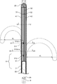
- FIG. 2 shows a longitudinal sectional view of the distal portion of the catheter shown in FIG.
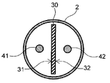
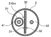
- FIG. 4 shows a VV cross-sectional view of the distal portion of the catheter shown in FIG.
- FIG. 4 shows a VI-VI cross-sectional view of the distal portion of the catheter shown in FIG.
- the VII-VII cross-sectional view of the distal portion of the catheter shown in FIG. 4 is shown.
- FIG. 4 shows a side view of the inside of the shaft of the distal portion A of the catheter shown in FIG.
- FIG. 6 shows a longitudinal sectional view of the distal portion of the catheter according to still another embodiment of the present invention. Represents a rigidity measurement method. Another example of the VV cross-sectional view of the distal portion of the catheter shown in FIG. 4 is shown.
- the catheter of the present invention has a shaft having a distal end and a proximal end and having a longitudinally extending lumen; a distal end and a proximal end, the distal end of which is the shaft.
- the proximal end With the first and second wires anchored to the distal end, the proximal end being located at the proximal end of the shaft and extending into the lumen of the shaft;
- a leaf spring located in the lumen of the shaft so as to separate into a first part where one wire is placed and a second part where the second wire is placed;
- With a support member that has a cavity in which the second wire is located the proximal end of the leaf spring is fixed, and is located proximal to the leaf spring;
- a first coil having a cavity, distal to the distal end of the support member and located within the first portion, the first coil at least at two locations on the proximal end side of the leaf spring.
- the first fixed part which is fixed and the part where the first coil and the leaf spring are fixed, and the part where the first coil and the leaf spring are fixed, located on the proximal side of the first fixed part. It has a second fixed portion and an intermediate non-fixed portion that is located between the first fixed portion and the second fixed portion and is not fixed to the leaf spring, and the first coil is in a natural state. It has the total length L 1 in the above and the total length L C 1 at the time of maximum compression, and has the above-mentioned first coil whose ratio L C1 / L 1 is 0.9 or more.
- the distal portion of the catheter can be bent on both one side and the other side of the leaf spring in the radial direction of the shaft, and the catheter is curved toward one side of the leaf spring. It is possible to use an asymmetrically curved type catheter in which the curved shape at the time and the curved shape at the time of bending to the other side of the leaf spring are different. Therefore, the catheter of the present invention can easily deliver the distal portion of the catheter to a desired position in a blood vessel or heart.
- the difference in the curved shape means that the shape when curved to one side and the shape when curved to the other side are different, and includes that the size of the circle along the curved shape, in other words, the radius is different.
- the difference in curve shape between the curved shape on one side and the curved shape on the other side particularly the difference in size, can be made larger, so that the curve of various shapes of blood vessels can be obtained. Can be accommodated.
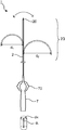
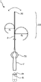
- 1 to 3 show a plan view of the catheter according to the embodiment of the present invention
- the dotted line shows the state when the distal portion of the catheter is curved toward one side and the other side of the leaf spring in the radial direction of the shaft.
- the dotted line in FIG. 2 shows the state when the distal portion of the catheter is further curved as compared with the case shown in FIG.
- the dotted line in FIG. 3 shows the state when the distal portion of the catheter is further curved as compared with the case shown in FIG.
- FIG. 4 shows a sectional view of the distal portion of the catheter shown in FIG.
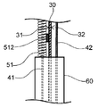
- FIG. 8 shows a side view of the first wire and the second wire, the leaf spring, the support member, and the first coil arranged in the shaft lumen in the portion A of the distal portion of the catheter shown in FIG.
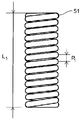
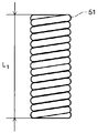
- FIG. 9 shows a side view of the first coil according to the embodiment of the present invention in a natural state
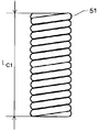
- FIG. 10 shows a side view of the first coil shown in FIG. 9 at the time of maximum compression.
- FIG. 11 shows a side view of the first coil according to another embodiment of the present invention in a natural state.
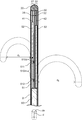
- FIG. 12 shows a longitudinal sectional view of the distal portion of the catheter according to another embodiment of the present invention, and the dotted line indicates that the distal portion of the catheter is curved toward one side and the other side of the leaf spring in the radial direction of the shaft. It shows the state of time.
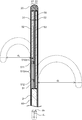
- FIG. 13 shows a longitudinal sectional view of the distal portion of the catheter according to still another embodiment of the present invention, and the dotted line indicates that the distal portion of the catheter is curved toward one side and the other side of the leaf spring in the radial direction of the shaft. It shows the state when it was done.
- FIG. 14 shows a method for measuring rigidity.
- FIG. 15 represents another example of a VV cross section of the distal catheter shown in FIG.
- the proximal side refers to the user's hand side with respect to the extending direction of the shaft
- the distal side refers to the opposite side of the proximal side, that is, the treatment target side.
- the extending direction of the shaft is referred to as a longitudinal direction d L.
- the radial direction d R refers to the radial direction perpendicular to the extending direction of the shaft.
- the lower side of the figure is the proximal side
- the upper side of the figure is the distal side.
- a one side of the leaf spring left figure in the radial direction d R of the shaft, the other right side of the figure is of the leaf spring in the radial direction d R of the shaft It is on the direction side.
- the catheter 1 has a shaft 2 having a distal end and a proximal end and having a lumen extending in the longitudinal direction d L. It is preferable that the tip portion 20 is arranged at the distal end of the shaft 2, and it is preferable that the handle 7 is arranged at the proximal end of the shaft 2.
- the shaft 2 is inserted into the body from the distal end and delivered to the treatment site. Therefore, it is preferably flexible, and a metal or resin can be used as the material. Since it is inserted into the body, it is preferable to use a biocompatible material.
- a device for treatment such as an electrode and a sensor can be arranged on the surface of the shaft 2. By providing an electrode on the surface of the shaft 2, it can be used as an electrode catheter for measuring electrocardiographic potential or an ablation catheter for cauterizing tissue.
- the lumen of the shaft 2 may be a single lumen or may be partially composed of a plurality of lumens.
- the structure for curvature of the present invention is arranged in a single lumen.
- the curved portion may be a single lumen, and a plurality of lumens proximal to the lumen may be formed.
- the lumen may have a double structure.
- the length, outer diameter, thickness, etc. of the shaft in the longitudinal direction d L can be selected from an appropriate size for treatment.
- the tip portion 20 is arranged at the distal end of the shaft 2.
- the tip portion 20 may be a member different from the shaft 2 or may be the same member.
- the tip portion 20 may include a portion inserted into the lumen of the shaft 2 or a portion protruding distally from the distal end of the shaft. ..
- the tip portion 20 is formed by closing the opening of the distal end portion of the shaft 2 by heat fusion or the like of the distal end portion of the shaft 2. You may.
- the handle 7 is arranged on the proximal side of the shaft 2, and it is preferable that the proximal end of the shaft 2 is fixed to the inside of the handle 7.
- a conducting wire and an operating wire extending from the lumen of the shaft 2 are arranged inside the handle 7.
- the handle 7 may include a wire operating portion 70 so that the operating wire can be easily operated. By fixing the proximal end of the operating wire to the wire operating portion 70, the wire operating portion 70 can be operated to pull the wire or the like and bend the distal end of the catheter 1.
- the catheter 1 has a distal end and a proximal end within the lumen of the shaft 2, with the distal end being the distal end of the shaft 2, eg, the tip 20.
- the first wire 41 and the first wire 41 and the proximal end are located at the proximal end of the shaft 2, eg, the handle 7, and extend into the lumen of the shaft 2 (eg, extend from the tip 20 to the handle 7). It has two wires 42, a distal end and a proximal end, and in the longitudinal direction d L , the cavity of the shaft 2 is arranged, the first part 21 in which the first wire 41 is arranged, and the second wire 42 are arranged.
- leaf spring 30 arranged so as to be separated from the second part 22, a distal end and a proximal end , extending in the longitudinal direction d L , and the first wire 41 and the second wire 42 are It has an arranged cavity, a proximal end of the leaf spring 30 is fixed, and a support member 60 arranged proximal to the leaf spring 30 is arranged.
- the first wire 41 and the second wire 42 are operation wires for bending the distal shaft portion 2D of the catheter 1. It is preferred that the first wire 41 and the second wire 42 are arranged in the lumen of the shaft 2, with the distal end fixed to the tip 20 and the proximal end fixed to the handle 7.
- a metal wire rod such as stainless steel or a wire rod formed of a synthetic resin such as fluororesin can be used.
- the first wire 41 and the second wire 42 may each have one wire rod or may have a structure composed of a plurality of wire rods.
- the leaf spring 30 is a member that defines the bending direction of the catheter 1, and a first portion 21 in which the first wire 41 is arranged and a second wire 42 are arranged in the lumen of the shaft 2 in the longitudinal direction d L. It is arranged so as to separate the lumen of the shaft 2 from the second part 22 to be formed.
- the proximal end of the leaf spring 30 is fixed to the support member 60.
- the distal end of the leaf spring 30 is preferably fixed to the distal end of the shaft 2.
- the tip portion 20 is provided at the distal end of the shaft 2, it is preferably fixed to the tip portion 20.
- the distal end of the leaf spring 30 does not have to be fixed.
- the distal end or the proximal end of the leaf spring 30 may be fixed by not directly fixing the end portion but fixing the vicinity thereof.
- the method for fixing the distal end and the proximal end of the leaf spring 30 is not particularly limited, and examples thereof include brazing of solder and the like, welding, adhesion with an adhesive, connection by caulking, and the like. ..
- the tip portion 20 and the support member 60 are made of metal, they are preferably fixed by laser welding.
- the leaf spring 30 has a distal end and a proximal end, and has a shape extending in the longitudinal direction d L.
- the leaf spring 30 is preferably arranged along the longitudinal axis of the shaft 2.
- the lumen of the shaft 2 is partitioned by the leaf spring 30 into two parts, a first part 21 on one side including the longitudinal axis of the shaft 2 and a second part 22 on the other side.
- the first wire 41 is arranged in one first portion 21 of the lumen of the partitioned shaft 2, and the second wire 42 is arranged in the second portion 22 of the other.
- the surface of the leaf spring 30 on the side where the first wire 41 is arranged is referred to as the first surface 31, and the surface of the leaf spring 30 on the side where the second wire 42 is arranged is referred to as the second surface 32. It can be said that the first surface 31 of the leaf spring 30 is one surface and the second surface 32 is the other surface.
- the leaf spring 30 is a spring using a plate material, and examples of the material constituting the leaf spring 30 include metals such as stainless steel, titanium, carbon steel, nickel-titanium alloy, cobalt-chromium alloy, and tungsten alloy.
- examples of the material constituting the leaf spring 30 include synthetic resins such as aromatic polyetherketone resin (for example, PEEK), polycarbonate resin, and fiber reinforced resin.
- the leaf spring 30 may be made of synthetic rubber such as butadiene rubber, isoprene rubber, styrene butadiene rubber, ethylene propylene rubber, acrylic rubber, silicone rubber, or natural rubber. Above all, the material of the leaf spring 30 is preferably stainless steel.
- the support member 60 is arranged on the proximal side of the leaf spring 30 in the lumen of the shaft 2, and the first wire 41 and the second wire 42 are arranged in the lumen.
- the proximal end of the leaf spring 30 is fixed to the distal end of the support member 60.
- the proximal end of the support member 60 may extend to the proximal end of the shaft 2 or may be located in the middle of the shaft 2.
- the support member 60 may be switched to a different member, for example, a tube or the like in the middle of the shaft 2.
- the support member 60 may be a proxy tube having a tubular shape. If the support member 60 is a proxy tube, the proxy tube can accept the proximal end of the leaf spring 30 and a portion of the leaf spring 30 can be placed in the lumen of the proxy tube. Thereby, the fixing between the leaf spring 30 and the support member 60 can be strengthened.
- the support member 60 is preferably flexible like the shaft 2, and a metal or resin can be used as the material. Of these, a coil around which a metal wire is wound is preferable. Since the internal structure of the catheter 1 of the present invention is switched at the distal end of the support member 60, the change in hardness of the catheter 1 does not become large between the distal end and the proximal side of the support member 60. , The size, flexibility and material of the support member 60 are preferably selected.
- the catheter 1 has a lumen in which the first wire 41 is arranged, and includes a first coil 51 arranged distal to the distal end of the support member 60.
- the first coil 51 is arranged on the proximal end side of the leaf spring 30, and is fixed to the proximal end side of the leaf spring 30 at at least two places.
- the arrangement on the proximal end side of the leaf spring 30 means that it is arranged on the portion near the proximal end of the leaf spring, and the proximal end of the first coil 51 is adjacent to the distal end of the support member 60. Or it means that they are arranged in close proximity.
- the first coil 51 is a member that regulates the bending of the leaf spring 30 toward one side 31 side, when the first coil 51 is fixed to the distal side of the leaf spring 30, the leaf spring 30 is on one side. It becomes impossible to bend to the 31 side.
- the first coil 51 has a first fixing portion 511, which is a portion where the first coil 51 and the leaf spring 30 are fixed, a second fixing portion 512 located proximal to the first fixing portion, and a first fixing portion. It has an intermediate non-fixed portion 510 m which is located between the portion 511 and the second fixed portion 512 and is not fixed to the leaf spring 30.
- the first coil 51 can be made of a metal wire such as stainless steel or nickel-titanium alloy, or a synthetic resin wire such as aromatic polyetherketone resin (for example, PEEK) or polycarbonate resin.
- the cross-sectional shape of the wire forming the first coil 51 can be circular, quadrangular, or a combination thereof.
- the first coil 51 is preferably a metal coil made of stainless steel and using a wire having a circular cross section.
- the wire diameter, coil diameter, and length of the first coil 51 can be appropriately selected as needed.
- first coil 51 and the leaf spring 30 are fixed by welding, soldering, bonding, or pressure welding. Above all, fixing by welding is preferable. If it is fixed by welding, the first fixing portion 511 and the second fixing portion 512 can be formed without using a material such as solder or an adhesive.
- the fixing of the first coil 51 and the leaf spring 30 is the direct fixing of the first coil 51 and the leaf spring 30, the fixing by the proximal end of the first coil 51 in contact with the support member 60, or the first.
- the first coil 51 and the leaf spring 30 may be indirectly fixed by fixing the one coil 51 to the support member 60 by welding, soldering, bonding, or pressure welding.
- the second fixing portion 512 may be a fixing portion fixed by the proximal end of the first coil 51 being in contact with the support member 60, or the second fixing portion 512 may be the first coil 51.
- the first coil 51 and the leaf spring 30 may be indirectly fixed by being fixed to the support member 60 by welding, soldering, bonding, or pressure welding.
- the positions of the first fixing portion 511 and the second fixing portion 512 in the longitudinal direction d L are not particularly limited, and may be arranged anywhere on the surface of the first coil 51.
- the first fixing portion 511 may be arranged at the distal end of the first coil 51
- the second fixing portion 512 may be arranged at the proximal end of the first coil 51.
- a fixing portion may be further provided in addition to the first fixing portion 511 and the second fixing portion 512.
- the total number of fixed portions is two or more, and may have more than two fixed portions.
- the first coil 51 can be fixed to the leaf spring 30 so that the leaf spring 30 on the proximal side from the fixing portion on the most distal side does not bend toward the one side 31 side.
- the length of the fixed portion of the first coil 51 including the first fixed portion 511 and the second fixed portion 512 and the leaf spring 30 in the longitudinal direction d L can be appropriately set, but in the longitudinal direction d L of the fixed portion.
- the length is preferably short, and as shown in FIG. 8, it is preferably as long as, for example, about three wires forming a coil. If the length of the fixed portion in the longitudinal direction d L is long, the flexibility when the catheter 1 bends toward the other surface 32 may be lost.
- the first coil 51 has a total length L 1 in a natural state and a total length L C 1 at the time of maximum compression.
- the ratio, L C1 / L 1 is 0.9 or more.
- the first coil 51 is preferably uncompressed as shown in FIG.
- the uncompressed coil is a tightly wound coil, that is, a coil that is not compressed in the longitudinal direction d L, and has a total length L 1 of the coil in the natural state and a total length L C 1 of the coil at the time of maximum compression.
- the ratio of L C1 / L 1 is 1, but when L C1 / L 1 is 0.9 or more and 0.95 or more, it is substantially uncompressed and is included in the uncompressed coil.
- L C1 / L 1 is preferably 0.95 or more.
- the distal shaft portion 2D can be curved to either one side or the other side, and each curved shape can be a different shape.
- the respective curved diameters can be different, and the degree of difference in the curved diameter can be strictly controlled.
- the first coil 51 is fixed to the leaf spring 30 at at least two points on the proximal side of the leaf spring 30, and the first coil 51 is an uncompressed coil, the first coil is the leaf spring 30. It cannot be curved in the non-side, that is, in the direction of one side 31. This is because since the uncompressed coil is fixed at two points, the first coil 51 cannot be compressed with respect to the curvature to one surface between the two points, and functions and behaves as a rigid tube. Therefore, in the leaf spring 30, only the portion between the portion fixed to the tip portion 20 and the fixed portion on the most distal side of the first coil 51 can be bent toward one side.
- the first coil 51 can be curved toward one side 31 side as well as the leaf spring 30. Further, if the first coil 51 is not an uncompressed coil, the coil can be extended with respect to one side and the other side, and can be curved toward one side. Therefore, the leaf spring 30 can be curved to one side 31 side in the range from the distal side to the proximal side regardless of whether the first coil 51 is fixed at two points with the leaf spring 30 or is incompressible. Will be.
- the second wire 42 arranged in the second portion 22 of the lumen of the shaft 2 of the catheter 1 is pulled.
- the leaf spring 30 is curved toward the other surface 32, and the distal shaft portion 2D of the catheter 1 is curved toward the other surface 32.
- the first coil 51 arranged on the one side 31 side of the leaf spring 30 is curved on the other side 32 side of the leaf spring 30 by increasing the distance between the coil strands of the non-fixed portion on the one side of the coil. Following it, it can be curved toward the other surface 32 side. Therefore, the leaf spring 30 can be bent toward the other surface 32 in all the portions from the portion fixed to the tip portion 20 to the distal end of the support member 60.
- the portion where the first coil 51 and the leaf spring 30 are fixed is preferably located on the surface of the first coil 51 facing the one surface 31 of the leaf spring 30. As a result, the bending of the first coil 51 toward the leaf spring 30 side, that is, the other surface 32 side is not hindered.
- the intermediate non-fixed portion 510 m which is a portion without a fixed portion between the first fixed portion 511 and the second fixed portion 512 of the first coil 51, has a length in the natural state of the longitudinal direction d L of the first coil 51. It is preferably 50% or more of the total length L 1 in the natural state.
- the length of the longest intermediate non-fixed portion 510 m in the longitudinal direction d L in the natural state may be 50% or more of the total length L 1 in the natural state of the first coil 51. preferable.
- the length of the longest intermediate non-fixed portion 510 m of the first coil 51 is such that the length in the natural state of the longitudinal direction d L is 30% or more of the total length L 1 in the natural state of the first coil 51. It may be 20% or more. Even in such a range, it is possible to prevent the bending of the first coil 51 toward the one side 31 side and not to hinder the bending toward the other surface 32 side.
- the length of the longest intermediate non-fixed portion 510 m in the longitudinal state d L in the natural state is long. Even if the value is smaller than 50% of the total length L 1 of the first coil 51 in the natural state, it is possible to effectively prevent the first coil 51 from bending toward one surface 31 side.
- the curved shape of the curved portion on the distal side of the catheter 1 can be controlled.
- the curvature toward the one side 31 side is formed by the portion between the fixing portion of the distal end portion of the shaft 2 of the first wire 41 and the fixing portion on the most distal side of the first coil 51, and is formed on the other side 32 side. This is because the curvature to is formed by the portion of the second wire 42 from the fixation point at the distal end of the shaft 2 to the distal end of the support member 60.
- the first coil 51 does not have a fixing portion for fixing the first coil 51 and the leaf spring 30 between the distal end of the first coil 51 and the first fixing portion 511.
- the bendable portion distal to the first coil 51 It is possible to prevent the shape of the curvature from being extremely changed between the first coil 51 and the portion that does not bend toward the one surface 31 side proximal to the fixed portion on the most distal side. For example, if the most distal fixation portion of the first coil 51 is at the distal end of the first coil 51, the catheter 1 may break at the distal end of the first coil 51.
- the catheter 1 may further include a second coil 52.
- the second coil 52 has a lumen in which the first wire 41 is arranged, and is a first portion 21 partitioned by a leaf spring 30 in the lumen of the shaft 2, and is distal to the first coil 51. Placed on the side.
- the second coil 52 may be in contact with any portion such as the leaf spring 30 in the lumen of the shaft 2, but it is preferable that the second coil 52 is not fixed to any portion.
- the catheter 1 may further include a third coil 53.
- the third coil 53 has a lumen in which the second wire 42 is arranged, and is arranged in the second portion 22 partitioned by the leaf spring 30 in the lumen of the shaft 2.
- the third coil 53 may be in contact with any portion such as the leaf spring 30 in the lumen of the shaft 2, but it is preferable that the third coil 53 is not fixed to any portion.
- the second coil 52 has a total length L 2 in the natural state and a total length L C 2 at the time of maximum compression, as in FIGS. 9 and 10 for the first coil 51.
- L C2 / L 2 is more preferably less than 0.9 and more preferably less than L C1 / L 1 .
- the third coil 53 has a total length L 3 in a natural state and a total length L C 3 at the time of maximum compression.
- L C3 / L 3 is more preferably less than 0.9 and more preferably less than L C1 / L 1 .
- the ratio L C1 / L 1 of the total length L 1 in the natural state of the first coil 51 to the total length L C 1 at the time of maximum compression is the ratio L C2 / L 2 and L C3 / L of the second coil 52 and the third coil 53.
- the first coil 51 is the same as or more easily deformed than the second coil 52 and the third coil 53, and it becomes difficult to control the curved shape of the catheter 1.
- the lengths of the first coil 51, the second coil 52, and the third coil 53 can be appropriately selected according to the shape of the required curvature in the catheter 1.
- the first wire 41 and the second wire 42 may be partially exposed between the tip portion 20 and the support member 60 as shown in FIG. 12, and the first coil 51 may be partially exposed as shown in FIG.
- the second coil 52, and the third coil 53 may be all arranged in the lumen.
- the first coil 51 and the third coil 53 can be arranged so as to be in contact with the support member 60.
- the first coil 51 and the third coil 53 may be arranged with a slight distance from the support member 60, and the first wire 41 and the second wire 42 may be exposed. This also applies to the relationship between the tip portion 20, the second coil 52, and the third coil 53.
- the first coil 51 and the second coil 52 may be in contact with each other or may have a gap.
- the first coil 51, the second coil 52, and the third coil 53 are made of spirally wound coil wires.
- the pitch intervals of the first coil 51, the second coil 52, and the third coil 53 can be appropriately set.
- the pitch interval of the coils is the interval between the adjacent coil wires forming the coil and the center points of the coil wires.
- Pitch interval can be measured as the pitch spacing P 1 of the first coil 51 shown in FIG.
- the pitch interval is larger than the thickness of the coil streaks, there is a gap between the coil streaks and the coil can be compressed.
- L C / L approximates the coil wire diameter / pitch interval.
- L C1 / L 1 of the first coil 51 is 0.9 or more
- the coil wire diameter / pitch interval of the first coil 51 is 0.9 or more.
- the coil wire diameter and the coil diameter of the second coil 52 and the third coil 53 are appropriately selected according to the shape of the required curvature in the catheter 1. Can be done.
- metal or resin can be used as mentioned as the material of the first coil.
- the total length L of the coil in the natural state and the total length L C of the coil at the time of maximum compression can be controlled not only by the pitch interval but also by the coil wire diameter, coil diameter, material and the like of the coil.
- the pitch interval P 1 of the first coil 51 is preferably smaller than the pitch interval of the second coil 52 or the pitch interval of the third coil 53.
- the pitch interval By setting the pitch interval in this way, the total length L of the coil in the natural state and the total length L C of the coil at the time of maximum compression are appropriately adjusted, and L C2 / L 2 and L C3 / L 3 are L C1 /. It can be smaller than L 1.
- the pitch interval P 1 of the first coil 51 is preferably smaller than the pitch interval of the second coil 52.
- the coil wire diameter and the coil diameter of the first coil 51 are the same as the coil wire diameter and the coil diameter of the second coil 52.
- the coil wire diameter is the diameter of the wire forming the coil, and the coil diameter is the diameter of the coil.
- the pitch interval of the second coil 52 may be the same as or different from the pitch interval of the third coil 53.
- the pitch spacing of the second coil 52 and the pitch spacing of the third coil 53 may be such that the coil is not completely compressed when it is bent to the maximum. Since the first coil 51 is present, the bending diameter of the curvature toward one surface 31 side of the catheter 1 is smaller than the bending diameter of the curvature toward the other surface 32 side, and the second coil 52 is larger than the third coil 53. It gets shorter. Since the second coil 52 is shorter than the third coil 53, the second coil 52 is more likely to be completely compressed, and from this point, it is better to set the pitch interval of the second coil 52 to be wider.
- the coil wire diameter and coil diameter of the second coil 52 may be the same as or different from the coil wire diameter and coil diameter of the third coil 53, but are preferably the same. Since the pitch interval of the second coil 52 is different from the pitch interval of the third coil 53, the shape of the curvature of the catheter 1 toward the one side 31 side and the shape of the curvature toward the other surface 32 side can be made different. ..
- the coil wire diameter and coil diameter of the first coil 51 may be the same as those of the second coil 52 and the third coil 53, or may be different.
- the bending rigidity of the first coil 51 is larger than the bending rigidity of the second coil 52, and the difference between the bending rigidity of the first coil 51 and the bending rigidity of the second coil 52 is preferably 50% or less.
- the shape of the curvature when the shaft distal portion 2D is curved toward the one side 31 side of the leaf spring 30 can be made smooth.
- the method for adjusting the rigidity include selection of the type and amount of wire rod constituting each coil, adjustment of the inner and outer diameters of each coil, adjustment of the pitch interval of each coil, and the like.
- Rigidity can be obtained by a three-point bending test as shown in FIG.
- the three-point bending test was performed according to JIS K7171.
- the rigidity measurement sample 603 was placed on the two fulcrums 602 arranged on the support base 601 at a distance of the fulcrum distance D, and the indenter 604 arranged at the center of the fulcrum distance D was moved by a certain distance in the vertical direction.
- the load F at the time is measured, and this load F is taken as the rigidity of the rigidity measurement sample 603.
- the catheter 1 having the above configuration has a curved shape and a distal shaft portion when the distal shaft portion 2D is curved toward one side 31 of the leaf spring 30 by the first coil 51.
- the curved shape when the 2D is curved toward the other surface 32 of the leaf spring 30 can be different.
- the bending diameter d 1 when the shaft distal portion 2D is curved toward the one side 31 side of the leaf spring 30, and the bending diameter d when the shaft distal portion 2D is curved toward the other surface 32 side of the leaf spring 30. Can be smaller than 2.
- the curvature diameter d 1 is the diameter of the circumscribed circle on the outer surface of the shaft distal portion 2D curved toward one surface 31 side of the leaf spring 30 on the first wire 41 side, and the curvature of the shaft distal portion 2D. Is the diameter of the circle if is part of the arc.
- the bending diameter d 2 is the diameter of the circumscribed circle on the outer surface of the shaft distal portion 2D curved toward the other surface 32 side of the leaf spring 30 on the second wire 42 side, and the curvature of the shaft distal portion 2D is formed. If it is part of an arc, it is the diameter of the circle.
- the curved circumscribed circle does not necessarily have to be a perfect circle.
- the curved shape may be a shape on an circumscribed circle or a combination of straight lines and curves instead of an arc.
- the shape of the curvature on the one side 31 side and the shape of the curvature on the other side 32 side can be different depending on the first coil 51.
- the catheter 1 has a lumen and further has a protective tube 80 disposed in the lumen of the shaft 2, with a leaf spring 30 and a first coil in the lumen of the protective tube 80. It is preferable that the 51, the second coil 52, and the third coil 53 are arranged. A material similar to the material forming the shaft 2 can be used for forming the protective tube 80.
- the protective tube 80 can protect the leaf spring 30, the first coil 51, the second coil 52, the third coil 53, and the first wire 41 and the second wire 42.
- the protective tube 80 may be in contact with any portion, but is preferably fixed to the support member 60. Thereby, the protective tube 80 can prevent the coil from moving in the shaft 2.
Landscapes
- Health & Medical Sciences (AREA)
- Life Sciences & Earth Sciences (AREA)
- Engineering & Computer Science (AREA)
- Anesthesiology (AREA)
- Biophysics (AREA)
- Pulmonology (AREA)
- Biomedical Technology (AREA)
- Heart & Thoracic Surgery (AREA)
- Hematology (AREA)
- Animal Behavior & Ethology (AREA)
- General Health & Medical Sciences (AREA)
- Public Health (AREA)
- Veterinary Medicine (AREA)
- Mechanical Engineering (AREA)
- Media Introduction/Drainage Providing Device (AREA)
Abstract
L'objectif de la présente invention est de fournir un cathéter de type à courbure asymétrique dans lequel la forme incurvée d'une section distale du cathéter diffère entre un côté et l'autre côté. Ce cathéter comprend : un corps ; un premier fil et un second fil ; un ressort plat agencé de façon à diviser une cavité interne dans le corps en une première section dans laquelle le premier fil est agencé et en une seconde section dans laquelle le second fil est agencé ; un élément de support ; et un premier enroulement comportant une cavité interne dans laquelle le premier fil est agencé. Le premier enroulement est fixé au niveau d'au moins deux emplacements sur le côté d'extrémité proximale du ressort plat, le premier enroulement présente une longueur totale L1 dans son état normal et une longueur totale LC1 lorsqu'il est comprimé au maximum, et le rapport LC1/L1 associé est supérieur ou égal à 0,9.
Priority Applications (3)
| Application Number | Priority Date | Filing Date | Title |
|---|---|---|---|
| US17/928,720 US20230302258A1 (en) | 2020-06-04 | 2021-05-27 | Catheter |
| JP2022528784A JPWO2021246292A1 (fr) | 2020-06-04 | 2021-05-27 | |
| CN202180038919.8A CN115666702A (zh) | 2020-06-04 | 2021-05-27 | 导管 |
Applications Claiming Priority (2)
| Application Number | Priority Date | Filing Date | Title |
|---|---|---|---|
| JP2020-097338 | 2020-06-04 | ||
| JP2020097338 | 2020-06-04 |
Publications (1)
| Publication Number | Publication Date |
|---|---|
| WO2021246292A1 true WO2021246292A1 (fr) | 2021-12-09 |
Family
ID=78831077
Family Applications (1)
| Application Number | Title | Priority Date | Filing Date |
|---|---|---|---|
| PCT/JP2021/020269 WO2021246292A1 (fr) | 2020-06-04 | 2021-05-27 | Cathéter |
Country Status (4)
| Country | Link |
|---|---|
| US (1) | US20230302258A1 (fr) |
| JP (1) | JPWO2021246292A1 (fr) |
| CN (1) | CN115666702A (fr) |
| WO (1) | WO2021246292A1 (fr) |
Citations (5)
| Publication number | Priority date | Publication date | Assignee | Title |
|---|---|---|---|---|
| JP3232308B2 (ja) * | 1990-02-02 | 2001-11-26 | ボストン サイエンティフィック リミテッド | カテーテル操縦機構 |
| WO2012098788A1 (fr) * | 2011-01-19 | 2012-07-26 | 日本ライフライン株式会社 | Cathéter possédant une extrémité de guidage pliable |
| JP2013103131A (ja) * | 2011-11-10 | 2013-05-30 | Biosense Webster (Israel) Ltd | 直線運動を増倍する医療機器制御ハンドル |
| JP2014117399A (ja) * | 2012-12-14 | 2014-06-30 | River Seikoo:Kk | 医療用カセーター及び医療用カセーターの製造方法 |
| JP2014128675A (ja) * | 2012-12-31 | 2014-07-10 | Biosense Webster (Israel) Ltd | 両方向性作動用の単一牽引ワイヤを備えた二重ループラッソー |
-
2021
- 2021-05-27 US US17/928,720 patent/US20230302258A1/en active Pending
- 2021-05-27 WO PCT/JP2021/020269 patent/WO2021246292A1/fr active Application Filing
- 2021-05-27 CN CN202180038919.8A patent/CN115666702A/zh active Pending
- 2021-05-27 JP JP2022528784A patent/JPWO2021246292A1/ja active Pending
Patent Citations (5)
| Publication number | Priority date | Publication date | Assignee | Title |
|---|---|---|---|---|
| JP3232308B2 (ja) * | 1990-02-02 | 2001-11-26 | ボストン サイエンティフィック リミテッド | カテーテル操縦機構 |
| WO2012098788A1 (fr) * | 2011-01-19 | 2012-07-26 | 日本ライフライン株式会社 | Cathéter possédant une extrémité de guidage pliable |
| JP2013103131A (ja) * | 2011-11-10 | 2013-05-30 | Biosense Webster (Israel) Ltd | 直線運動を増倍する医療機器制御ハンドル |
| JP2014117399A (ja) * | 2012-12-14 | 2014-06-30 | River Seikoo:Kk | 医療用カセーター及び医療用カセーターの製造方法 |
| JP2014128675A (ja) * | 2012-12-31 | 2014-07-10 | Biosense Webster (Israel) Ltd | 両方向性作動用の単一牽引ワイヤを備えた二重ループラッソー |
Also Published As
| Publication number | Publication date |
|---|---|
| JPWO2021246292A1 (fr) | 2021-12-09 |
| US20230302258A1 (en) | 2023-09-28 |
| CN115666702A (zh) | 2023-01-31 |
Similar Documents
| Publication | Publication Date | Title |
|---|---|---|
| US20220111176A1 (en) | Introducer with steerable distal tip section | |
| RU2636180C2 (ru) | Двойная петля с одинарным управляющим проводом для двухстороннего действия | |
| US7972323B1 (en) | Steerable device for introducing diagnostic and therapeutic apparatus into the body | |
| US7842025B2 (en) | Dual-function catheter handle | |
| EP1627598B1 (fr) | Cathéter à dispositif de cartographie | |
| EP1545680B1 (fr) | Dispositif medical d'exploration anatomique | |
| EP2417999B1 (fr) | Fil-guide courbé muni d'un élément de maintien de courbure | |
| WO2011132409A1 (fr) | Cathéter | |
| AU2010208618B2 (en) | Guidewire | |
| US20210378648A1 (en) | Steerable instrument comprising a tube element | |
| WO2016047499A1 (fr) | Fil-guide | |
| CA2422034A1 (fr) | Stylet pouvant etre dirige, a resistance amelioree au transfert de torsion | |
| GB2456165A (en) | Slotted, flexible shaft for an endoscopic instrument | |
| KR20200030075A (ko) | 동축 원통형 요소들 사이에 반경방향 스페이서를 포함하는 조종가능한 기구 | |
| JP2004283461A (ja) | 先端偏向操作可能カテーテル | |
| WO2021246292A1 (fr) | Cathéter | |
| WO2020246037A1 (fr) | Fil-guide | |
| US20210290915A1 (en) | Guide wire | |
| JP6701082B2 (ja) | ガイドワイヤおよびガイドワイヤの製造方法 | |
| WO2022009566A1 (fr) | Cathéter | |
| WO2022009567A1 (fr) | Cathéter | |
| WO2023021801A1 (fr) | Cathéter | |
| WO2016136030A1 (fr) | Cathéter | |
| WO2024024349A1 (fr) | Dilatateur | |
| JP5174487B2 (ja) | カテーテル |
Legal Events
| Date | Code | Title | Description |
|---|---|---|---|
| 121 | Ep: the epo has been informed by wipo that ep was designated in this application |
Ref document number: 21818059 Country of ref document: EP Kind code of ref document: A1 |
|
| ENP | Entry into the national phase |
Ref document number: 2022528784 Country of ref document: JP Kind code of ref document: A |
|
| NENP | Non-entry into the national phase |
Ref country code: DE |
|
| 122 | Ep: pct application non-entry in european phase |
Ref document number: 21818059 Country of ref document: EP Kind code of ref document: A1 |