WO2021246286A1 - 光学要素、画像表示装置、仮想現実表示装置、電子ファインダー、偏光子の製造方法 - Google Patents
光学要素、画像表示装置、仮想現実表示装置、電子ファインダー、偏光子の製造方法 Download PDFInfo
- Publication number
- WO2021246286A1 WO2021246286A1 PCT/JP2021/020231 JP2021020231W WO2021246286A1 WO 2021246286 A1 WO2021246286 A1 WO 2021246286A1 JP 2021020231 W JP2021020231 W JP 2021020231W WO 2021246286 A1 WO2021246286 A1 WO 2021246286A1
- Authority
- WO
- WIPO (PCT)
- Prior art keywords
- polarizing element
- virtual line
- plate
- intersection
- group
- Prior art date
- Legal status (The legal status is an assumption and is not a legal conclusion. Google has not performed a legal analysis and makes no representation as to the accuracy of the status listed.)
- Ceased
Links
Images


Classifications
-
- G—PHYSICS
- G02—OPTICS
- G02B—OPTICAL ELEMENTS, SYSTEMS OR APPARATUS
- G02B5/00—Optical elements other than lenses
- G02B5/30—Polarising elements
- G02B5/3025—Polarisers, i.e. arrangements capable of producing a definite output polarisation state from an unpolarised input state
- G02B5/3033—Polarisers, i.e. arrangements capable of producing a definite output polarisation state from an unpolarised input state in the form of a thin sheet or foil, e.g. Polaroid
-
- B—PERFORMING OPERATIONS; TRANSPORTING
- B29—WORKING OF PLASTICS; WORKING OF SUBSTANCES IN A PLASTIC STATE IN GENERAL
- B29D—PRODUCING PARTICULAR ARTICLES FROM PLASTICS OR FROM SUBSTANCES IN A PLASTIC STATE
- B29D11/00—Producing optical elements, e.g. lenses or prisms
- B29D11/00634—Production of filters
- B29D11/00644—Production of filters polarizing
-
- B—PERFORMING OPERATIONS; TRANSPORTING
- B29—WORKING OF PLASTICS; WORKING OF SUBSTANCES IN A PLASTIC STATE IN GENERAL
- B29D—PRODUCING PARTICULAR ARTICLES FROM PLASTICS OR FROM SUBSTANCES IN A PLASTIC STATE
- B29D11/00—Producing optical elements, e.g. lenses or prisms
- B29D11/00865—Applying coatings; tinting; colouring
-
- G—PHYSICS
- G02—OPTICS
- G02B—OPTICAL ELEMENTS, SYSTEMS OR APPARATUS
- G02B17/00—Systems with reflecting surfaces, with or without refracting elements
- G02B17/02—Catoptric systems, e.g. image erecting and reversing system
- G02B17/023—Catoptric systems, e.g. image erecting and reversing system for extending or folding an optical path, e.g. delay lines
-
- G—PHYSICS
- G02—OPTICS
- G02B—OPTICAL ELEMENTS, SYSTEMS OR APPARATUS
- G02B23/00—Telescopes, e.g. binoculars; Periscopes; Instruments for viewing the inside of hollow bodies; Viewfinders; Optical aiming or sighting devices
- G02B23/14—Viewfinders
-
- G—PHYSICS
- G02—OPTICS
- G02B—OPTICAL ELEMENTS, SYSTEMS OR APPARATUS
- G02B27/00—Optical systems or apparatus not provided for by any of the groups G02B1/00 - G02B26/00, G02B30/00
- G02B27/0018—Optical systems or apparatus not provided for by any of the groups G02B1/00 - G02B26/00, G02B30/00 with means for preventing ghost images
-
- G—PHYSICS
- G02—OPTICS
- G02B—OPTICAL ELEMENTS, SYSTEMS OR APPARATUS
- G02B27/00—Optical systems or apparatus not provided for by any of the groups G02B1/00 - G02B26/00, G02B30/00
- G02B27/01—Head-up displays
- G02B27/017—Head mounted
- G02B27/0172—Head mounted characterised by optical features
-
- G—PHYSICS
- G02—OPTICS
- G02B—OPTICAL ELEMENTS, SYSTEMS OR APPARATUS
- G02B5/00—Optical elements other than lenses
- G02B5/30—Polarising elements
- G02B5/3016—Polarising elements involving passive liquid crystal elements
-
- G—PHYSICS
- G02—OPTICS
- G02F—OPTICAL DEVICES OR ARRANGEMENTS FOR THE CONTROL OF LIGHT BY MODIFICATION OF THE OPTICAL PROPERTIES OF THE MEDIA OF THE ELEMENTS INVOLVED THEREIN; NON-LINEAR OPTICS; FREQUENCY-CHANGING OF LIGHT; OPTICAL LOGIC ELEMENTS; OPTICAL ANALOGUE/DIGITAL CONVERTERS
- G02F1/00—Devices or arrangements for the control of the intensity, colour, phase, polarisation or direction of light arriving from an independent light source, e.g. switching, gating or modulating; Non-linear optics
- G02F1/01—Devices or arrangements for the control of the intensity, colour, phase, polarisation or direction of light arriving from an independent light source, e.g. switching, gating or modulating; Non-linear optics for the control of the intensity, phase, polarisation or colour
- G02F1/13—Devices or arrangements for the control of the intensity, colour, phase, polarisation or direction of light arriving from an independent light source, e.g. switching, gating or modulating; Non-linear optics for the control of the intensity, phase, polarisation or colour based on liquid crystals, e.g. single liquid crystal display cells
- G02F1/133—Constructional arrangements; Operation of liquid crystal cells; Circuit arrangements
- G02F1/1333—Constructional arrangements; Manufacturing methods
- G02F1/1335—Structural association of cells with optical devices, e.g. polarisers or reflectors
-
- G—PHYSICS
- G02—OPTICS
- G02F—OPTICAL DEVICES OR ARRANGEMENTS FOR THE CONTROL OF LIGHT BY MODIFICATION OF THE OPTICAL PROPERTIES OF THE MEDIA OF THE ELEMENTS INVOLVED THEREIN; NON-LINEAR OPTICS; FREQUENCY-CHANGING OF LIGHT; OPTICAL LOGIC ELEMENTS; OPTICAL ANALOGUE/DIGITAL CONVERTERS
- G02F1/00—Devices or arrangements for the control of the intensity, colour, phase, polarisation or direction of light arriving from an independent light source, e.g. switching, gating or modulating; Non-linear optics
- G02F1/01—Devices or arrangements for the control of the intensity, colour, phase, polarisation or direction of light arriving from an independent light source, e.g. switching, gating or modulating; Non-linear optics for the control of the intensity, phase, polarisation or colour
- G02F1/13—Devices or arrangements for the control of the intensity, colour, phase, polarisation or direction of light arriving from an independent light source, e.g. switching, gating or modulating; Non-linear optics for the control of the intensity, phase, polarisation or colour based on liquid crystals, e.g. single liquid crystal display cells
- G02F1/133—Constructional arrangements; Operation of liquid crystal cells; Circuit arrangements
- G02F1/1333—Constructional arrangements; Manufacturing methods
- G02F1/1335—Structural association of cells with optical devices, e.g. polarisers or reflectors
- G02F1/13363—Birefringent elements, e.g. for optical compensation
-
- G—PHYSICS
- G06—COMPUTING OR CALCULATING; COUNTING
- G06F—ELECTRIC DIGITAL DATA PROCESSING
- G06F1/00—Details not covered by groups G06F3/00 - G06F13/00 and G06F21/00
- G06F1/16—Constructional details or arrangements
- G06F1/1613—Constructional details or arrangements for portable computers
- G06F1/163—Wearable computers, e.g. on a belt
-
- G—PHYSICS
- G09—EDUCATION; CRYPTOGRAPHY; DISPLAY; ADVERTISING; SEALS
- G09F—DISPLAYING; ADVERTISING; SIGNS; LABELS OR NAME-PLATES; SEALS
- G09F9/00—Indicating arrangements for variable information in which the information is built-up on a support by selection or combination of individual elements
-
- H—ELECTRICITY
- H05—ELECTRIC TECHNIQUES NOT OTHERWISE PROVIDED FOR
- H05B—ELECTRIC HEATING; ELECTRIC LIGHT SOURCES NOT OTHERWISE PROVIDED FOR; CIRCUIT ARRANGEMENTS FOR ELECTRIC LIGHT SOURCES, IN GENERAL
- H05B33/00—Electroluminescent light sources
- H05B33/02—Details
-
- H—ELECTRICITY
- H10—SEMICONDUCTOR DEVICES; ELECTRIC SOLID-STATE DEVICES NOT OTHERWISE PROVIDED FOR
- H10K—ORGANIC ELECTRIC SOLID-STATE DEVICES
- H10K59/00—Integrated devices, or assemblies of multiple devices, comprising at least one organic light-emitting element covered by group H10K50/00
- H10K59/80—Constructional details
- H10K59/8791—Arrangements for improving contrast, e.g. preventing reflection of ambient light
Definitions
- the present invention relates to an optical element, an image display device, a virtual reality display device, an electronic finder, and a method for manufacturing a polarizing element.
- Absorption-type polarizing elements are widely used in image display devices such as liquid crystal displays and organic EL display devices, and these polarizing elements have substantially the same direction of absorption axes in the plane (linear). ) Often.
- image display devices such as virtual reality display devices and electronic viewfinders
- an image display device using a reciprocating optical system as described in Patent Document 1 has been used. Proposed.
- an absorption type polarizing element is used on the visual side in order to suppress an undesired image such as a ghost (hereinafter, also simply referred to as “ghost”) caused by stray light. It is desirable that the above-mentioned polarizing element also has a curved surface according to the shape of the lens.
- the present invention has been made in view of the above problems, and the problem of the present invention is the effect of suppressing ghosts when an absorption type polarizing element having a curved surface portion is applied to an image display device using a reciprocating optical system. Is to provide excellent optical elements.
- Another object of the present invention is to provide an image display device, a virtual reality display device, an electronic finder, and a method for manufacturing a polarizing element.
- a position X includes an absorption type polarizing element A having a curved surface portion and an absorption type polarizing element B, and the position on the polarizing element B side surface of the polarizing element A is the position X.
- the position Y is the position of the surface of the polarizing element B closest to X on the polarizing element A side and a straight line L passing through the position X and the position Y is drawn, the position X is observed from the position Y on the straight line L.
- An optical element in which a position Z satisfying a specific requirement exists at a position on the side beyond the position X.
- the direction of the absorption axis of the polarizing element A at the position X and the direction of the reflection axis of the reflected linear polarizing element at the intersection of the straight line L and the reflected linear polarizing element are parallel when observed from the direction in which the straight line L extends.
- the direction of the absorption axis of the polarizing element A at the intersection of the virtual lines L1 to L4 and the polarizing element A and the direction of the reflection axis of the reflected linear transducer at the intersection of the virtual lines L1 to L4 and the reflected linear polarizing element are.
- the image display device according to [5] wherein the virtual lines L1 to L4 are parallel to each other when observed from the extending direction.
- the angle formed by the direction of the absorption axis of the polarizing element A at the position X and the direction of the slow axis of the first ⁇ / 4 plate at the intersection of the straight line L and the first ⁇ / 4 plate is a straight line. When observed from the direction in which L extends, it is 45 ⁇ 10 °.
- the angle formed by the direction of the slow axis of the first ⁇ / 4 plate at the intersection with the plate is 45 ⁇ 10 °, respectively, when observed from the direction in which the virtual lines L1 to L4 extend.
- Image display device is an angle formed by the direction of the absorption axis of the polarizing element A at the position X and the direction of the slow axis of the first ⁇ / 4 plate at the intersection of the straight line L and the first ⁇ / 4 plate.
- the angle formed by the direction of the absorption axis of the polarizing element A at the position X and the direction of the slow axis of the first ⁇ / 4 plate at the intersection of the straight line L and the first ⁇ / 4 plate is the straight line L.
- it is 45 ⁇ 10 °
- the angle formed by the direction of the slow axis of the first ⁇ / 4 plate at the intersection with the polarized light is 45 ⁇ 10 ° when observed from the direction in which the virtual lines L1 to L4 extend.
- Image display device [10] The image display device according to [9], wherein the reflective circular polarizing element has a cholesteric liquid crystal layer. [11] The image display device according to any one of [5] to [10], wherein the polarizing element B is laminated on the image display element. [12] A virtual reality display device including the image display device according to any one of [5] to [11]. [13] An electronic finder comprising the image display device according to any one of [5] to [11].
- the surface of the alignment film has a plurality of regions in which the directions of absorption axes are different from each other and has a curved surface portion, which comprises a step of spray-coating a composition containing a liquid crystal compound and a dichroic substance on the surface of the alignment film.
- the layer After forming a layer of a composition for forming a photoalignment film containing a photoalignment agent on the surface of a resin substrate, the layer is irradiated with linearly polarized ultraviolet rays through a lens to orient the photoalignment agent.
- an optical element having an excellent effect of suppressing ghosts when an absorption type polarizing element having a curved surface portion is applied to a virtual image display device using a reciprocating optical system. Further, according to the present invention, it is possible to provide an image display device, a virtual reality display device, an electronic finder, and a method for manufacturing a polarizing element.
- orthogonal does not mean exactly 90 °, but 90 ° ⁇ 10 °, preferably 90 ° ⁇ 5 °.
- parallel does not mean exactly 0 °, but means 0 ° ⁇ 10 °, preferably 0 ° ⁇ 5 °.
- 45 ° does not mean exactly 45 °, but means 45 ° ⁇ 10 °, preferably 45 ° ⁇ 5 °.
- the term “absorption axis” means the direction in which the absorbance is maximized in the plane.
- the “reflection axis” means a direction in which the reflectance is maximized in the plane.
- the “slow phase axis” means the direction in which the refractive index becomes maximum in the plane.
- the term “local” when referred to as “local absorption axis” does not mean the direction of the average absorption axis over the entire region of the film, but is local at one point of interest. It means that it is the direction of the absorption axis.
- the optical element according to the present invention includes an absorption type polarizing element A having a curved surface portion and an absorption type polarizing element B, and a specific position of the polarizing element A. It is an optical element in which a position Z satisfying the requirements described later exists on a straight line L connecting X and a specific position Y of the polarizing element B.
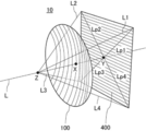
- FIG. 1 shows an example of the configuration of the optical element according to the present invention.
- the optical element 10 shown in FIG. 1 has a polarizing element A100 and a polarizing element B400.
- the polarizing element A100 is an absorption type polarizing element having a curved surface
- the polarizing element B400 is a planar absorption type polarizing element.
- the optical element 10 has a position X on the surface of the polarizing element A on the side of the polarizing element B, which is the position closest to the position X, and is located on the side of the polarizing element A of the polarizing element B closest to the position X.
- A There are a virtual line L1, a virtual line L2, a virtual line L3, and a virtual line L4 that pass through the position Z and form an angle with the straight line L at 30 °.
- B The angle formed by the straight line Lp1 normally projected onto the polarizing element B of the virtual line L1 and the straight line Lp2 directly projected onto the polarizing element B of the virtual line L2 is 90 °, and the straight line Lp2 and the virtual line L3 have an angle of 90 °.
- the angle formed by the straight line Lp3 projected normally on the polarizing element B is 90 °
- the angle formed by the straight line Lp3 and the straight line Lp4 directly projected onto the polarizing element B of the virtual line L4 is 90 °
- the angle formed by Lp1 is 90 °.
- the angle formed by the straight line Lp1 and the absorption axis of the polarizing element B is 45 °.
- D The direction of the absorption axis of the polarizing element A at the position X and the direction of the absorption axis of the polarizing element B at the position Y are orthogonal to each other when observed from the direction in which the straight line L extends.
- the direction of the absorption axis of the polarizing element A at the intersection of the virtual line L1 and the polarizing element A and the direction of the absorption axis of the polarizing element B at the intersection of the virtual line L1 and the polarizing element B are the directions of the virtual line L1. When observed from the extending direction, they are orthogonal.
- the direction of the absorption axis of the polarizing element A at the intersection of the virtual line L2 and the polarizing element A and the direction of the absorption axis of the polarizing element B at the intersection of the virtual line L2 and the polarizing element B are the directions of the virtual line L2. When observed from the extending direction, they are orthogonal.
- the direction of the absorption axis of the polarizing element A at the intersection of the virtual line L3 and the polarizing element A and the direction of the absorption axis of the polarizing element B at the intersection of the virtual line L3 and the polarizing element B are the directions of the virtual line L3. When observed from the extending direction, they are orthogonal.
- the direction of the absorption axis of the polarizing element A at the intersection of the virtual line L4 and the polarizing element A and the direction of the absorption axis of the polarizing element B at the intersection of the virtual line L4 and the polarizing element B are the directions of the virtual line L4. When observed from the extending direction, they are orthogonal.
- the present inventor has a position Z that satisfies the above specific requirements in an optical element having an absorption type polarizing element A having a curved surface and an absorption type polarizing element B.
- an image display using an absorption type polarizing element having a curved surface portion is used. It has been found that the device can also improve the effect of suppressing ghosts.
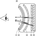
- FIG. 2 is a schematic view showing an example of the configuration of an image display device using a conventional reciprocating optical system.
- an absorption type polarizing element 31 having at least a curved surface, a reflection polarizing element 32, a half mirror 33, and an absorption type polarizing element 34.
- the image display device 30 includes an image display element 35. Further, the image display device 30 includes a retardation plate such as a ⁇ / 4 plate (not shown).
- a retardation plate such as a ⁇ / 4 plate (not shown).
- the light ray V emitted from the image display element 35 is reflected by the reflective polarizing element 32 and the half mirror 33, reciprocates inside the optical system, and the reflected polarizing element 32. After passing through the absorption type polarizing element 34, the light is emitted from a lens (not shown) on the viewing side.
- the conventional reciprocating optical system has been designed with the intention that the light ray V is appropriately reflected and polarized.
- the absorption type polarizing element 31 has a curved surface
- the local absorption axis of the absorption type polarizing element 31 at the intersection of the straight line connecting the viewpoint O and the absorption type polarizing element 31 and the absorption type polarizing element 31 is the absorption type polarized light. Due to the fact that the local absorption axis of the absorption type polarizing element 34 at the intersection of the child 34 and the straight line is not exactly orthogonal to each other, the light ray S may not be sufficiently shielded and the ghost may not be sufficiently suppressed. I found out.
- the absorption axis of the polarizing element A100 and the absorption axis of the polarizing element B400 are arranged at each intersection on the straight line at a position separated from the polarizing element A100 side.
- the polarizing element A100 and the polarizing element B400 are configured so that there is a position Z where the straight line L and the virtual lines L1 to L4 intersect so that the angle formed by the elements is 90 °. Therefore, by observing the optical element 10 from the position Z when it is used in the image display device, it is possible to suppress the light beam S emitted without reciprocating inside the optical system in the absorption type polarizing element A100 having a curved surface portion. It is possible to suppress the occurrence of ghosts in the observed display image. In particular, the above-mentioned excellent action and effect are more remarkable with respect to the suppression of ghosts in the image display region closer to the peripheral edge of the image display element.
- the position Z in the optical element can be specified by, for example, the following method. First, in the optical element, the position X on the polarizing element B side is searched for on the surface of the polarizing element A on the polarizing element B side. Subsequently, the position Y on the surface of the polarizing element B closest to the position X on the polarizing element A side is searched for. Based on the confirmed position X and position Y, a straight line L passing through the position X and the position Y is determined.
- the perpendicular line drawn from the position X to the polarizing element B is the straight line L
- the intersection of the perpendicular line and the surface of the polarizing element B on the splitter A side is the position Y.
- the position Y is located at the center of the polarizing element B.
- the angle between the line Lp1 which is the orthogonal projection of the virtual line Lw1 on the polarizing element B and the line Lp2 which is the orthogonal projection of the virtual line Lw2 on the polarizing element B is 90 °, and the line Lp2 and the virtual line are formed.
- the angle between the line Lp3 and the line Lp3, which is an orthogonal projection of the Lw3 onto the splitter B, is 90 °
- the angle between the line Lp3 and the line Lp4, which is the orthogonal projection of the virtual line Lw4 onto the polarizing element B is 90 °.
- the angle between the line Lp4 and the line Lp1 is 90 °, and the angle between the line Lp1 and the absorption axis of the polarizing element B is 45 °.
- the polarizing element B is removed from the optical element so that the direction of the measurement beam of the AxoScan coincides with the virtual line Lw1 and the positions of the virtual line Lw1 and the polarizing element A.
- the polarizing element A is fixed and the absorption axis is measured so as not to change the relationship.
- the polarizing element A is removed from the optical element so that the direction of the measurement beam of the AxoScan coincides with the virtual line Lw1 and the virtual line Lw1 and the polarizing element are measured.
- the absorber B is fixed and the absorption axis is measured so as not to change the positional relationship of B.
- it is determined whether or not the virtual line Lw1 is 90 ° when observed from the extending direction. Similar measurements and determinations are performed for the straight line L and the virtual lines Lw2 to Lw4.
- the point W is set. Specified as position Z.
- the virtual lines Lw1 to Lw4 passing through the point W (position Z) at this time correspond to the virtual lines L1 to L4 specified in the above specific requirements, respectively.
- the virtual line L1, the virtual line L2, the virtual line L3, and the virtual line L4 are all different, and the straight line Lp1, the straight line Lp2, the straight line Lp3, and the straight line Lp4 are all different.
- the absorption-type polarizing element A having a curved surface portion and the absorption-type polarizing element B included in the optical element are configured so that there is a position Z in which both the polarizing elements A and B satisfy specific requirements.
- the term "polarizer having a curved surface portion" means that at least a part of the polarizing element is formed of a curved surface. It is preferable that the polarizing element A is entirely formed of a curved surface. Further, the polarizing element A preferably has a three-dimensional curved surface, and is preferably formed entirely of the three-dimensional curved surface.
- the three-dimensional curved surface refers to a curved surface that is not a developable surface.
- a developable surface means a curved surface that can be developed into a plane without expanding and contracting, that is, a curved surface that can be created by bending or cutting the plane.
- the polarizing element A preferably has a rotating surface having a convex surface on the polarizing element B side and a concave surface on the surface opposite to the polarizing element B side, and may have a curved surface having a constant radius of curvature. More preferred.
- the constant radius of curvature means that the difference between the maximum value and the minimum value of the radius of curvature on the surface of the optical member such as the modulator A is within 5% with respect to the minimum value of the radius of curvature. means.
- the radius of curvature can be appropriately selected depending on the size and application of the optical element and the image display device, but is preferably 20 to 1000 mm, more preferably 30 to 200 mm.
- the polarizing element B may be planar or may have a curved surface portion. When the polarizing element B has a curved surface portion, it may be the same as the above-mentioned polarizing element A, including a preferred embodiment.
- this optical element absorbs the local absorption axis of the polarizing element A at the intersection with the straight line Lz and the local absorption of the polarizing element B at the intersection with the straight line Lz. It is preferable that the relationship between the position Z, the polarizing element A and the polarizing element B, that the angle formed with the axis is 90 ° when observed from the direction in which the straight line Lz extends, is satisfied over the entire region of the polarizing element B. By satisfying the above relationship over the entire region of the polarizing element B, ghosts generated in the displayed image can be more effectively suppressed in the image display device produced by using the present optical element. It should be noted that the measurement of whether or not the optical element satisfies the above relationship can be performed according to the above-mentioned method for specifying the position Z.
- the polarizing element A is an absorption type polarizing element.
- a known absorption type polarizing element having at least a light absorption anisotropic layer containing a dichroic substance can be used.
- the light absorption anisotropic layer include a layer containing a matrix compound and a dichroic substance, and a layer containing a liquid crystal compound and a dichroic substance is preferable.
- the degree of orientation of the dichroic substance in the light absorption anisotropic layer is preferably 0.95 or more, more preferably 0.97 or more. The higher the degree of orientation, the more effectively the ghost can be suppressed.
- the upper limit of the degree of orientation is not particularly limited, and may be 0.99 or less, preferably 0.98 or less.
- the polarizing element A has a plurality of regions in which the directions of the absorption axes are different from each other. That is, it is preferable that there are two or more regions in the plane of the polarizing element A in which the directions of the local absorption axes are not parallel to each other.
- FIG. 3 shows an example of the orientation distribution of the absorption axis when the polarizing element A has a plurality of regions in which the directions of the absorption axes are different from each other.
- FIG. 3 is a schematic diagram showing the distribution of the orthogonal projection of the polarizing element A on the plane (polarizer B) of the local absorption axis. In FIG. 3, each “AA” indicates the direction of the normal projection of the absorption axis. show.
- the absorption axis in the polarizing element A can be measured by using AxoScan OPMF-1 as described above (method for specifying the position Z).
- the polarizing element A having an absorption axis oriented as described above can be formed, for example, by the method described in ⁇ Method for forming a light absorption anisotropic layer >> described later.
- the absorption axis in the polarizing element A is not limited to the above embodiment as long as the position Z satisfying the specific requirement exists. For example, a position Z that satisfies a specific requirement may be present due to a combination of a polarizing element A having absorption axes parallel to the whole and a polarizing element B having a plurality of regions having different absorption axes.
- the decoder A may contain a resin base material.
- the peak temperature of tan ⁇ of the resin base material is 170 ° C. or lower. From the viewpoint of enabling molding at a lower temperature, the peak temperature of tan ⁇ is preferably 150 ° C. or lower, and the peak temperature of tan ⁇ is more preferably 130 ° C. or lower.
- the resin base material is not particularly limited, and a base material made of various optical resins can be used, but a resin base material having a peak temperature of tan ⁇ of 170 ° C. or less is preferable.
- the resin constituting such a resin base material include polyethylene, polypropylene, and polyolefins such as norbornene-based polymers; cyclic olefin-based resins; polyvinyl alcohol; polyethylene terephthalates; polymethacrylic acid esters and polyacrylic acid esters.
- Acrylic resins polyethylene naphthalates; polycarbonates; polysulfones; polyethersulfones; polyetherketones; as well as polyphenylene sulfides and polyphenylene oxides.
- a cyclic olefin resin, polyethylene terephthalate or an acrylic resin is preferable, and a cyclic olefin resin or a polymethacrylic acid ester is more preferable, because they are easily available on the market and have excellent transparency.
- resin substrates include Technoroy S001G, Technoroy S014G, Technoroy S000, Technoroy C001, and Technoroy C000 (Sumika Acrylic Sales Co., Ltd.), Lumirror U type, Lumirror FX10, and Lumirror SF20 (Toray Co., Ltd.).
- HK-53A Higashiyama Film Co., Ltd.
- Teflex FT3 Teijin DuPont Film Co., Ltd.
- Scina and SCA40 Sekisui Chemical Industry Co., Ltd.
- Zeonoa Film Optes Co., Ltd.
- Arton Film JSR Co., Ltd.
- the thickness of the resin base material is not particularly limited, but is preferably 5 to 300 ⁇ m, more preferably 5 to 100 ⁇ m, and even more preferably 5 to 30 ⁇ m.
- the light absorption anisotropic layer preferably contains a liquid crystal compound and a dichroic substance.
- a light absorption anisotropic layer can be formed by using a composition containing a liquid crystal compound and a dichroic substance (hereinafter, also referred to as "composition for forming a light absorption anisotropic layer"). It is preferable that the liquid crystal compound and / or the dichroic substance contained in the composition for forming a light absorption anisotropic layer has a radically polymerizable group in that the decrease in the degree of polarization during heating is suppressed.
- the molar content of the radically polymerizable group is preferably 0.6 mmol / g or more, preferably 1.0 mmol / g or more, with respect to the solid content weight of the composition for forming a light absorption anisotropic layer. More preferably, it is more preferably 1.5 mmol / g or more.
- the upper limit is not particularly limited, but is preferably 5 mmol / g or less.
- the composition for forming a light absorption anisotropic layer contains a liquid crystal compound.
- the liquid crystal compound is preferably a liquid crystal compound that does not exhibit dichroism in the visible region.
- the liquid crystal compound either a low molecular weight liquid crystal compound or a high molecular weight liquid crystal compound can be used.
- the "low molecular weight liquid crystal compound” means a liquid crystal compound having no repeating unit in the chemical structure.
- the “polymer liquid crystal compound” means a liquid crystal compound having a repeating unit in the chemical structure. Examples of the low molecular weight liquid crystal compound include liquid crystal compounds described in paragraphs [0027] to [0034] of JP2013-228706A.
- low molecular weight liquid crystal compounds exhibiting smectic properties are preferable.
- the polymer liquid crystal compound include thermotropic liquid crystal polymers described in JP-A-2011-237513.
- the polymer liquid crystal compound preferably has a crosslinkable group (for example, an acryloyl group and a methacryloyl group) at the terminal.
- the liquid crystal compound may be used alone or in combination of two or more. It is also preferable to use a high molecular weight liquid crystal compound and a low molecular weight liquid crystal compound in combination.
- the content of the liquid crystal compound is preferably 25 to 2000 parts by mass, more preferably 33 to 1000 parts by mass with respect to 100 parts by mass of the content of the dichroic substance in the composition for forming a light absorption anisotropic layer. , 50 to 500 parts by mass is more preferable.
- the degree of orientation of the polarizing element is further improved.
- the liquid crystal compound is preferably a polymer liquid crystal compound because the degree of orientation of the obtained light absorption anisotropic layer is higher, and is a repeating unit represented by the following formula (1) (hereinafter, "repetition"). It is more preferable that the polymer liquid crystal compound contains a unit (1) ”.
- P1 represents the main chain of the repeating unit
- L1 represents a single bond or a divalent linking group
- SP1 represents a spacer group
- M1 represents a mesogen group
- T1 represents a terminal group. ..
- Examples of the main chain of the repeating unit represented by P1 include groups represented by the following formulas (P1-A) to (P1-D), and among them, the diversity and handling of the raw material monomers can be mentioned. From the viewpoint of simplicity, a group represented by the following formula (P1-A) is preferable.
- R 1 represents a hydrogen atom or a methyl group.
- R 2 represents an alkyl group.
- the group represented by the formula (P1-A) is a poly (meth) acrylic acid ester obtained by polymerization of the (meth) acrylic acid ester because the degree of orientation of the obtained light absorption anisotropic layer is higher. It is preferably one unit of the partial structure.
- the group represented by the formula (P1-B) is preferably an ethylene glycol unit in polyethylene glycol obtained by polymerizing ethylene glycol because the degree of orientation of the obtained light absorption anisotropic layer is higher. ..
- the group represented by the formula (P1-C) is preferably a propylene glycol unit obtained by polymerizing propylene glycol because the degree of orientation of the obtained light absorption anisotropic layer is higher.
- the group represented by the formula (P1-D) is preferably a siloxane unit of polysiloxane obtained by polycondensation of silanol because the degree of orientation of the obtained light absorption anisotropic layer is higher.
- L1 is a single bond or divalent linking group.
- the divalent linking groups represented by L1 are -C (O) O-, -OC (O)-, -O-, -S-, -C (O) NR 3- , -NR 3 C (O). -, - SO 2 -, and, -NR 3 R 4 -, and the like.
- R 3 and R 4 each independently represent a hydrogen atom and an alkyl group having 1 to 6 carbon atoms which may have a substituent.
- P1 is a group represented by the formula (P1-A)
- L1 is represented by —C (O) O— because the degree of orientation of the obtained light absorption anisotropic layer is higher. Groups are preferred.
- P1 is a group represented by the formulas (P1-B) to (P1-D)
- L1 is preferably a single bond because the degree of orientation of the obtained light absorption anisotropic layer is higher.
- the spacer group represented by SP1 is at least selected from the group consisting of an oxyethylene structure, an oxypropylene structure, a polysiloxane structure and a fluorinated alkylene structure because of its tendency to exhibit liquid crystallinity and the availability of raw materials. It preferably contains one type of structure.
- oxyethylene structure represented by SP1 is, * - (CH 2 -CH 2 O) n1 - * groups represented by are preferred.
- n1 represents an integer of 1 to 20, and * represents the coupling position with L1 or M1 in the above formula (1).
- n1 is preferably an integer of 2 to 10, more preferably an integer of 2 to 4, and most preferably 3 because the degree of orientation of the obtained light absorption anisotropic layer is higher. preferable.
- the group represented by *-(CH (CH 3 ) -CH 2 O) n2- * is used because the degree of orientation of the obtained light absorption anisotropic layer is higher. preferable.
- n2 represents an integer of 1 to 3, and * represents the coupling position with L1 or M1.
- the polysiloxane structure represented by SP1 is preferably a group represented by *-(Si (CH 3 ) 2- O) n3- * because the degree of orientation of the obtained light absorption anisotropic layer is higher. ..
- n3 represents an integer of 6 to 10
- * represents the coupling position with L1 or M1.
- the fluoroalkylene structure represented by SP1 is preferably a group represented by *-(CF 2- CF 2 ) n4- * because the degree of orientation of the obtained light absorption anisotropic layer is higher.
- n4 represents an integer of 6 to 10
- * represents the coupling position with L1 or M1.
- the mesogen group represented by M1 is a group showing the main skeleton of a liquid crystal molecule that contributes to the formation of a liquid crystal.
- the liquid crystal molecule exhibits liquid crystallinity, which is an intermediate state (mesophase) between the crystalline state and the isotropic liquid state.
- the mesogen group is not particularly limited, and for example, "Flussige Kristalle in Tabellen II” (VEB Manual Verlag fur Grundstoff Industrie, Leipzig, 1984), especially the description on pages 7 to 16, and the LCD Handbook Editorial Board. You can refer to the description in the edition, LCD Handbook (Maruzen, 2000) (especially Chapter 3).
- the mesogen group is preferably a group having at least one cyclic structure selected from the group consisting of, for example, an aromatic hydrocarbon group, a heterocyclic group, and an alicyclic group.
- the mesogen group preferably has an aromatic hydrocarbon group, and more preferably 2 to 4 aromatic hydrocarbon groups, because the degree of orientation of the obtained light absorption anisotropic layer is higher. It is more preferred to have three aromatic hydrocarbon groups.
- the mesogen group the following formula (M1-A) or the following formula (M1) is used from the viewpoints of developing liquid crystallinity, adjusting the liquid crystal phase transition temperature, availability of raw materials and synthetic suitability, and the effect of the present invention is more excellent.
- the group represented by —B) is preferable, and the group represented by the formula (M1-B) is more preferable.
- A1 is a divalent group selected from the group consisting of aromatic hydrocarbon groups, heterocyclic groups and alicyclic groups. These groups may be substituted with an alkyl group, an alkyl fluoride group, an alkoxy group or a substituent.
- the divalent group represented by A1 is preferably a 4- to 6-membered ring. Further, the divalent group represented by A1 may be a monocyclic ring or a condensed ring. * Represents the binding position with SP1 or T1.
- Examples of the divalent aromatic hydrocarbon group represented by A1 include a phenylene group, a naphthylene group, a fluorene-diyl group, an anthracene-diyl group, a tetracene-diyl group, and the like. From the viewpoint of properties and the like, a phenylene group or a naphthylene group is preferable, and a phenylene group is more preferable.
- the divalent heterocyclic group represented by A1 may be either aromatic or non-aromatic, but a divalent aromatic heterocyclic group is preferable from the viewpoint of further improving the degree of orientation. ..
- Examples of the atom other than carbon constituting the divalent aromatic heterocyclic group include a nitrogen atom, a sulfur atom and an oxygen atom.
- the aromatic heterocyclic group has a plurality of atoms constituting a ring other than carbon, they may be the same or different.
- divalent aromatic heterocyclic group examples include pyridylene group (pyridine-diyl group), pyridazine-diyl group, imidazole-diyl group, thienylene (thiophene-diyl group), and quinolylene group (quinolin-diyl group).
- Isoquinolylene group isoquinolin-diyl group
- oxazole-diyl group thiazole-diyl group
- oxadiazol-diyl group benzothiazole-diyl group
- benzothiazol-diyl group benzothiazol-diyl group
- phthalimide-diyl group thienothiazole-diyl group
- divalent alicyclic group represented by A1 examples include a cyclopentylene group and a cyclohexylene group.
- a1 represents an integer from 1 to 10.
- the plurality of A1s may be the same or different.
- A2 and A3 are each independently a divalent group selected from the group consisting of aromatic hydrocarbon groups, heterocyclic groups and alicyclic groups. Specific examples and preferred embodiments of A2 and A3 are the same as those of A1 of the formula (M1-A), and thus the description thereof will be omitted.
- a2 represents an integer of 1 to 10, and when a2 is 2 or more, a plurality of A2s may be the same or different, and a plurality of A3s may be the same or different. Often, the plurality of LA1s may be the same or different.
- a2 is preferably an integer of 2 or more, and more preferably 2 because the degree of orientation of the obtained light absorption anisotropic layer is higher.
- M1-B when a2 is 1, LA1 is a divalent linking group.
- the plurality of LA1s are independently single-bonded or divalent linking groups, and at least one of the plurality of LA1s is a divalent linking group.
- a2 it is preferable that one of the two LA1s is a divalent linking group and the other is a single bond because the degree of orientation of the obtained light absorption anisotropic layer is higher. ..
- M1 include the following structures.
- Ac represents an acetyl group.
- the terminal group represented by T1 includes a hydrogen atom, a halogen atom, a cyano group, a nitro group, a hydroxy group, an alkyl group having 1 to 10 carbon atoms, an alkoxy group having 1 to 10 carbon atoms, and an alkylthio group having 1 to 10 carbon atoms.
- the (meth) acryloyloxy group-containing group include -LA (L represents a single bond or a linking group. Specific examples of the linking group are the same as those of L1 and SP1 described above.
- A is (meth).
- a group represented by (representing an acryloyloxy group) can be mentioned.
- T1 an alkoxy group having 1 to 10 carbon atoms is preferable, an alkoxy group having 1 to 5 carbon atoms is more preferable, and a methoxy group is further preferable, because the degree of orientation of the obtained light absorption anisotropic layer is higher.
- These terminal groups may be further substituted with these groups or the polymerizable group described in JP-A-2010-244038.
- the number of atoms in the main chain of T1 is preferably 1 to 20, more preferably 1 to 15, further preferably 1 to 10, and even more preferably 1 to 7 because the degree of orientation of the obtained light absorption anisotropic layer is higher. Is particularly preferable.
- the degree of orientation of the modulator is further improved.
- the "main chain" in T1 means the longest molecular chain bonded to M1, and the hydrogen atom is not counted in the number of atoms in the main chain of T1.
- T1 is an n-butyl group
- the number of atoms in the main chain is 4, and when T1 is a sec-butyl group, the number of atoms in the main chain is 3.
- the content of the repeating unit (1) is 20 to 100% by mass with respect to 100% by mass of all the repeating units of the polymer liquid crystal compound because the degree of orientation of the obtained light absorption anisotropic layer is higher. Is preferable. In the present specification, the content of each repeating unit contained in the polymer liquid crystal compound is calculated based on the charged amount (mass) of each monomer used to obtain each repeating unit.
- the repeating unit (1) may be contained alone or in combination of two or more in the polymer liquid crystal compound. Among them, it is preferable that the polymer liquid crystal compound contains two kinds of the repeating unit (1) because the degree of orientation of the obtained light absorption anisotropic layer is higher.
- the terminal group represented by T1 in one is an alkoxy group because the degree of orientation of the obtained light absorption anisotropic layer is higher.
- the terminal group represented by T1 is preferably a group other than the alkoxy group.
- the terminal group represented by T1 in the repeating unit B is an alkoxycarbonyl group, a cyano group, or a (meth) acryloyloxy group-containing group because the degree of orientation of the obtained light absorption anisotropic layer is higher. Is preferable, and an alkoxycarbonyl group or a cyano group is more preferable.
- the ratio (A / B) of the content of the repeating unit A in the polymer liquid crystal compound and the content of the repeating unit B in the polymer liquid crystal compound is the degree of orientation of the obtained light absorption anisotropic layer. Is preferably 50/50 to 95/5, more preferably 60/40 to 93/7, and even more preferably 70/30 to 90/10.
- the polymer liquid crystal compound may further contain a repeating unit represented by the following formula (3-2) (also referred to as “repeating unit (3-2)” in the present specification). This has advantages such as improved solubility of the polymer liquid crystal compound in a solvent and easy adjustment of the liquid crystal phase transition temperature.
- the repeating unit (3-2) differs from the repeating unit (1) in that it has at least no mesogen group.
- the polymer liquid crystal compound may be a copolymer of the repeating unit (1) and the repeating unit (3-2), and further. , May be a copolymer containing the repeating units A and B.
- the copolymer may be any polymer such as a block polymer, an alternate polymer, a random polymer, and a graft polymer.
- P3 represents the backbone of the repeating unit
- L3 represents a single bond or a divalent linking group
- SP3 represents a spacer group
- T3 represents a terminal group.
- P3, L3, SP3 and T3 in the formula (3-2) are the same as P1, L1, SP1 and T1 in the above formula (1), respectively.
- T3 in the formula (3-2) preferably has a polymerizable group from the viewpoint of improving the strength of the light absorption anisotropic layer.
- the content is preferably 0.5 to 40% by mass, more preferably 1 to 30% by mass, based on 100% by mass of all the repeating units of the polymer liquid crystal compound. ..
- the repeating unit (3-2) may be contained alone or in combination of two or more in the polymer liquid crystal compound. When two or more types of repeating units (3-2) are included, the total amount thereof is preferably within the above range.
- the weight average molecular weight (Mw) of the polymer liquid crystal compound is preferably 1000 to 500,000, more preferably 2000 to 300,000 because the degree of orientation of the obtained light absorption anisotropic layer is higher.
- Mw of the polymer liquid crystal compound is within the above range, the handling of the polymer liquid crystal compound becomes easy.
- the weight average molecular weight (Mw) of the polymer liquid crystal compound is preferably 10,000 or more, and more preferably 10,000 to 300,000.
- the weight average molecular weight (Mw) of the polymer liquid crystal compound is preferably less than 10,000, and preferably 2000 or more and less than 10,000.
- the weight average molecular weight and the number average molecular weight described in the present specification are values measured by a gel permeation chromatograph (GPC) method.
- the content of the liquid crystal compound is preferably an amount of 50 to 99% by mass, more preferably 70 to 96% by mass, based on the solid content of the composition for forming a light absorption anisotropic layer.
- the "solid content in the composition for forming a light absorption anisotropic layer” refers to a component excluding the solvent. Specific examples of the solid content include the above liquid crystal compound, a dichroic substance described later, a polymerization initiator, and a surfactant.
- the composition for forming a light absorption anisotropic layer contains a dichroic substance.
- the bicolor substance is not particularly limited, and a known bicolor substance (bicolor dye) can be used.
- a visible light absorbing substance (bicolor dye), a luminescent substance (fluorescent substance, a phosphorescent substance) can be used.
- a visible light absorbing substance (bicolor dye)
- a luminescent substance fluorescent substance, a phosphorescent substance
- UV absorbers Ultraviolet absorbers, infrared absorbers, non-linear optical materials, carbon nanotubes, and inorganic materials (eg quantum rods).
- Examples of the bicolor substance include paragraphs [0067] to [0071] of JP2013-228706, paragraphs [0008] to [0026] of JP2013-227532, and JP2013-209367.
- the light absorption anisotropic layer may contain two or more kinds of dichroic substances.
- dichroic substances for example, from the viewpoint of bringing the obtained liquid crystal layer closer to black, at least one having a maximum absorption wavelength in the wavelength range of 370 to 550 nm. It is preferable to use the dichroic substance of the species in combination with at least one dichroic substance having a maximum absorption wavelength in the wavelength range of 500 to 700 nm.
- the dichroic substance contained in the composition for forming a light absorption anisotropic layer may have a crosslinkable group.
- the dichroic substance has a crosslinkable group.
- the crosslinkable group include a (meth) acryloyl group, an epoxy group, an oxetanyl group, and a styryl group, and among them, a (meth) acryloyl group is preferable.
- the content of the dichroic substance in the composition for forming the light absorption anisotropic layer is 1 to 400 parts by mass with respect to 100 parts by mass of the liquid crystal compound because the degree of orientation of the dichroic substance is higher. It is preferably 2 to 100 parts by mass, more preferably 5 to 30 parts by mass.
- the composition for forming a light absorption anisotropic layer may contain a surfactant.
- a surfactant contained in the composition for forming a light absorption anisotropic layer a known surfactant can be used, but it is also referred to as a repeating unit containing an alkyl fluoride group (hereinafter, also referred to as “repeating unit F”).
- a copolymer having a repeating unit containing a ring structure hereinafter, also abbreviated as “repeating unit M”) is preferable.
- the repeating unit F contained in the copolymer is preferably a repeating unit represented by the following formula (a).
- R a1 represents a hydrogen atom or an alkyl group having 1 to 20 carbon atoms
- R a2 represents an alkyl group having 1 to 20 carbon atoms having at least one carbon atom as a substituent a fluorine atom
- it represents an alkenyl group having 2 to 20 carbon atoms.
- Ra2 is an alkyl having 1 to 10 carbon atoms in which at least one carbon atom has a fluorine atom as a substituent because the orientation defect of the obtained light absorption anisotropic layer is further suppressed.
- a group or an alkenylene group having 2 to 10 carbon atoms is preferable, an alkyl group having 1 to 10 carbon atoms is more preferable, and more than half of the carbon atoms contained in Ra2 have a fluorine atom as a substituent. ..
- the repeating unit F contained in the copolymer is more preferably a repeating unit represented by the following formula (b).
- Ra1 represents a hydrogen atom or an alkyl group having 1 to 20 carbon atoms
- ma and na each independently represent an integer of 0 or more
- X represents a hydrogen atom or a fluorine atom.
- ma is preferably an integer of 1 or more and 10 or less
- na is preferably 4 or more and 12 or less.
- Examples of the monomer forming the repeating unit F of the copolymer include 2,2,2-trifluoroethyl (meth) acrylate, 2, 2,3,3,3-Pentafluoropropyl (meth) acrylate, 2- (perfluorobutyl) ethyl (meth) acrylate, 2- (perfluorohexyl) ethyl (meth) acrylate, 2- (perfluorooctyl) ethyl (Meta) acrylate, 2- (perfluorodecyl) ethyl (meth) acrylate, 2- (perfluoro-3-methylbutyl) ethyl (meth) acrylate, 2- (perfluoro-5-methylhexyl) ethyl (meth) acrylate , 2- (Perfluoro-7-methyloctyl) ethyl
- the ratio of copolymerizing the fluoroalkyl group-containing monomer is preferably 0.01 to 100 mol with respect to 1 mol of the monomer having a mesogen group described later, and 0. It is more preferably 1 to 50 mol, further preferably 1 to 30 mol.
- the repeating unit M contained in the copolymer may be a unit containing a ring structure.
- the ring structure include at least one ring structure selected from the group consisting of aromatic hydrocarbon groups, heterocyclic groups, and alicyclic groups. From the viewpoint of suppressing orientation defects, the repeating unit M preferably has two or more ring structures.
- the repeating unit M contained in the copolymer is more preferably a repeating unit represented by the following formula (b).
- Ra1 represents a hydrogen atom or an alkyl group having 1 to 20 carbon atoms
- L4 and L5 independently represent a single bond or an alkylene group having 1 to 8 carbon atoms, respectively, and G1 and G2.
- T4 represents a terminal group.
- n represents an integer of 0 to 4.
- two or more L5s may be the same or different
- two or more G2s may be the same or different.
- the hydrogen atom contained in one or more -CH 2- constituting the alkylene group is a halogen atom, a cyano group, a nitro group, a hydroxyl group, or a direct group having 1 to 10 carbon atoms. It may be replaced by at least one group selected from the group consisting of a chain alkyl group and a branched alkyl group having 1 to 10 carbon atoms.
- an alkyleneoxy group having 4 to 6 carbon atoms and an oxygen terminal is preferable
- an ester group is preferable.
- the divalent cyclic groups represented by G1 and G2 each independently represent a divalent alicyclic hydrocarbon group or an aromatic hydrocarbon group having 5 to 8 carbon atoms, and constitute the alicyclic hydrocarbon group.
- One or more of -CH 2- may be substituted with -O-, -S- or -NH-.
- the divalent cyclic group may be a divalent group formed by a single bond of a plurality of groups selected from an alicyclic hydrocarbon group and an aromatic hydrocarbon group. Of these, the benzene ring is preferable.
- the terminal group represented by T4 includes a hydrogen atom, a halogen atom, a cyano group, a nitro group, a hydroxy group, an alkyl group having 1 to 10 carbon atoms, an alkoxy group having 1 to 10 carbon atoms, and an alkylthio group having 1 to 10 carbon atoms.
- 1-10 acylamino group 1-10 carbon alkoxycarbonylamino group, 1-10 carbon sulfonylamino group, 1-10 carbon sulfamoyl group, 1-10 carbon carbamoyl group, 1-10 carbon carbon
- Examples thereof include 10 sulfinyl groups, ureido groups having 1 to 10 carbon atoms, and (meth) acryloyloxy group-containing groups. Of these, a hydrogen atom or a cyano group is preferable.
- the molar ratio of the repeating unit F to all the repeating units of the copolymer is preferably 50 mol% or more from the viewpoint of the degree of orientation, and is preferably 70 mol% or less from the viewpoint of repellent.
- the content of the above-mentioned surfactant is preferably 0.05 to 15 parts by mass with respect to 100 parts by mass of the above liquid crystal compound because the degree of orientation of the obtained light absorption anisotropic layer becomes higher. , 0.08 to 10 parts by mass, more preferably 0.1 to 5 parts by mass.
- the composition for forming a light absorption anisotropic layer preferably contains a polymerization initiator.
- the polymerization initiator is not particularly limited, but a photosensitive compound, that is, a photopolymerization initiator is preferable.
- the photopolymerization initiator various compounds can be used without particular limitation. Specific examples of the photopolymerization initiator include ⁇ -carbonyl compounds (US Pat. No. 2,376,661 and US Pat. No. 2,376,670), acidoin ethers (US Pat. No. 2,448,828), and ⁇ -carbonized compounds. Hydrogen-substituted aromatic acidoine compounds (US Pat. No.
- -029997 (Ab. 029997).
- a photopolymerization initiator a commercially available product can also be used. Examples of commercially available products of the photopolymerization initiator include Irgacure 184, Irgacure 907, Irgacure 369, Irgacure 651, Irgacure 819, Irgacure OXE-01 and Irgacure OXE-02 manufactured by BASF. ..
- the content of the polymerization initiator is the above dichroic substance and the above polymer liquid crystal compound in the composition for forming the light absorption anisotropic layer. 0.01 to 30 parts by mass is preferable, and 0.1 to 15 parts by mass is more preferable, with respect to 100 parts by mass in total.
- the content of the polymerization initiator is 0.01 parts by mass or more, the durability of the light absorption anisotropic film is good, and when it is 30 parts by mass or less, the degree of orientation of the light absorption anisotropic film is high. It will be better.
- the polymerization initiator may be used alone or in combination of two or more. When two or more kinds of polymerization initiators are contained, the total amount thereof is preferably within the above range.
- the composition for forming a light absorption anisotropic layer preferably contains a solvent from the viewpoint of workability and the like.
- the solvent include ketones (eg, acetone, 2-butanone, methylisobutylketone, cyclopetantanone, cyclohexanone, etc.), ethers (eg, dioxane, tetrahydrofuran, 2-methyltetrahexyl, cyclopentylmethyl ether, tetrahydropyran, etc.).
- Dioxolanes, etc. Dioxolanes, etc.), aliphatic hydrocarbons (eg, hexane, etc.), alicyclic hydrocarbons (eg, cyclohexane, etc.), aromatic hydrocarbons (eg, benzene, toluene, xylene, trimethylbenzene, etc.), halogenated Carbons (eg, dichloromethane, trichloromethane, dichloroethane, dichlorobenzene, chlorotoluene, etc.), esters (eg, methyl acetate, ethyl acetate, butyl acetate, ethyl lactate, etc.), alcohols (eg, ethanol, isopropanol, butanol, etc.) Cyclohexanols, isopentyl alcohols, neopentyl alcohols, diacetone alcohols, benzyl alcohols, etc.), cellosolves
- Examples include organic solvents such as sulfoxides), amides (eg, dimethylformamide, dimethylacetamide, N-methylpyrrolidone, N-ethylpyrrolidone, etc.), and heterocyclic compounds (eg, pyridine, etc.), and water.
- the solvent may be used alone or in combination of two or more.
- ketones particularly cyclopentanone or cyclohexanone
- ethers particularly tetrahydrofuran, cyclopentylmethyl ether, tetrahydropyran, or dioxolan
- dioxolanes or dioxolanes
- Amides particularly dimethylformamide, dimethylacetamide, N-methylpyrrolidone, or N-ethylpyrrolidone are preferred.
- the content of the solvent is preferably 80 to 99% by mass, preferably 83 to 97% by mass, based on the total mass of the composition for forming the light absorption anisotropic layer.
- the mass% is more preferable, and 85 to 95% by mass is particularly preferable.
- the solvent may be used alone or in combination of two or more. When two or more kinds of solvents are contained, the total amount thereof is preferably within the above range.
- the thickness of the light absorption anisotropic layer is not particularly limited, but is preferably 100 to 8000 nm, more preferably 300 to 5000 nm, from the viewpoint of reducing the thickness of the optical element.
- the decoder A may further have an alignment film, and preferably has an alignment film from the viewpoint of the orientation of the absorption axis of the light absorption anisotropic layer.
- the alignment film is not particularly limited as long as it has an alignment function, but a photoalignment film is preferable.
- the photo-alignment film that the polarizing element A may have is not particularly limited as long as it is an alignment film whose alignment function is generated by light irradiation, and a known photo-alignment film can be used.
- the material for forming the photoalignment film is not particularly limited, and examples thereof include a photoalignment agent.
- the photo-alignment film is formed by using, for example, a composition for forming a photo-alignment film containing a photo-alignment agent.
- the photo-aligning agent is a compound having a photo-aligning group.
- the compound having a photo-oriented group may be a polymer having a repeating unit containing a photo-oriented group.
- the photooriented group is a functional group that can impart anisotropy to the film by irradiation with light. More specifically, it is a group in which the molecular structure in the group can be changed by irradiation with light (for example, linearly polarized light).
- irradiation with light causes at least one photoreaction selected from a photoisomerization reaction, a photodimification reaction, and a photodegradation reaction.
- a group that causes a photoisomerization reaction a group having a photoisomerization structure
- a group that causes a photodimerization reaction a group having a photodimerization structure
- the group that causes the above is more preferable.
- the photoisomerization reaction refers to a reaction that causes stereoisomerization or structural isomerization by the action of light.
- the substance that causes such a photoisomerization reaction include a substance having an azobenzene structure (K. Ichimura et al., Mol. Cryst. Liq. Cryst., 298, page 221 (1997)) and hydrazono- ⁇ -. Substances with ketoester structure (S. Yamamura et al., Liquid Crystals, vol. 13, No.
- a group having a cinnamoyle structure or a group having a coumarin structure is preferable, and a group having a cinnamoyle structure is more preferable.
- the photodimerization reaction is a reaction in which an addition reaction occurs between two groups by the action of light, and a ring structure is typically formed.
- substances that cause such photodimerization include substances having a cinnamon acid structure (M. Schadt et al., J. Appl. Phys., Vol. 31, No. 7, page 2155 (1992)) and coumarin. Substances with structure (M. Schadt et al., Nature., Vol. 381, page 212 (1996)), Substances with coumarin structure (Toshihiro Ogawa et al., Proceedings of the LCD Discussion Meeting, 2AB03 (1997)), and , A substance having a benzophenone structure (YK Jang et al., SID Int.
- Examples of the group that causes the photodimerization reaction include a group having a cinnamon acid (cinnamoyl) structure (skeleton), a group having a coumarin structure (skeleton), a group having a chalcone structure (skeleton), and a benzophenone structure (skeleton).
- Examples include a group and a group having an anthracene structure (skeleton).
- a group having a cinnamoyle structure or a group having a coumarin structure is preferable, and a group having a cinnamoyle structure is more preferable.
- the compound having a photoalignable group further has a crosslinkable group.
- a crosslinkable group a heat-crosslinkable group that causes a curing reaction by the action of heat and a photocrosslinkable group that causes a curing reaction by the action of light are preferable, and both the crosslinkable group and the crosslinkable group have a photocrosslinkable group. It may be a group.
- the crosslinkable group include an epoxy group, an oxetanyl group, a group represented by -NH-CH 2 -OR (R represents a hydrogen atom or an alkyl group having 1 to 20 carbon atoms), and radical polymerization.
- Examples thereof include at least one selected from the group consisting of a sex group (a group having an ethylenically unsaturated double bond) and a blocked isocyanate group.
- a sex group a group having an ethylenically unsaturated double bond
- a blocked isocyanate group a group having an ethylenically unsaturated double bond
- an epoxy group, an oxetanyl group, or a group having an ethylenically unsaturated double bond is preferable.
- the cyclic ether group of the 3-membered ring is also called an epoxy group
- the cyclic ether group of the 4-membered ring is also called an oxetanyl group.
- Examples of the radically polymerizable group include a vinyl group, an allyl group, a styryl group, an acryloyl group and a methacryloyl group, which may be an acryloyl group or a methacryloyl group. preferable.
- One of the preferred embodiments of the photo-alignment film is a photo-alignment film formed by using a composition for forming a photo-alignment film containing a polymer A having a repeating unit a1 containing a cinnamate group.
- the cinnamate group is a group having a cinnamon acid structure containing cinnamon acid or a derivative thereof as a basic skeleton, and is a group represented by the following formula (I) or the following formula (II).
- R 1 represents a hydrogen atom or a monovalent organic group
- R 2 represents a monovalent organic group
- a represents an integer of 0 to 5
- a represents 0 to 4.
- the plurality of R 1s may be the same or different. * Indicates that it is a bond.
- the polymer A is not particularly limited as long as it is a polymer having a repeating unit a1 containing a cinnamate group, and a conventionally known polymer can be used.
- the weight average molecular weight of the polymer A is preferably 1000 to 500,000, more preferably 2000 to 300,000, still more preferably 3000 to 200,000.
- the weight average molecular weight is defined as a polystyrene (PS) conversion value measured by gel permeation chromatography (GPC), and the measurement by GPC in the present invention uses HLC-8220 GPC (manufactured by Tosoh Corporation) as a column. Measurement can be performed using TSKgel Super HZM-H, HZ4000, HZ2000.
- Examples of the repeating unit a1 containing the cinnamate group of the polymer A include repeating units represented by the following formulas (A1) to (A4).
- R 3 represents a hydrogen atom or a methyl group
- R 4 represents an alkyl group having 1 to 6 carbon atoms.
- L 1 represents a single bond or a divalent linking group
- a represents an integer from 0 to 5
- R 1 represents a hydrogen atom or a monovalent organic group.
- L 2 represents a divalent linking group and R 2 represents a monovalent organic group.
- L 1 for example, -CO-O-Ph-, -CO-O-Ph-Ph-, -CO-O- (CH 2 ) n- , -CO-O- (CH 2 ) n- Examples thereof include Cy- and-(CH 2 ) n- Cy-.
- Ph represents a divalent benzene ring which may have a substituent (for example, a phenylene group)
- Cy represents a divalent cyclohexane ring which may have a substituent (for example, cyclohexane-). It represents 1,4-diyl group, etc.)
- n represents an integer of 1 to 4.
- examples of L 2 include -O-CO-, -O-CO- (CH 2 ) m- O-, and the like.
- m represents an integer of 1 to 6.
- the monovalent organic group of R 1 for example, a chain or cyclic alkyl group having 1 to 20 carbon atoms, an alkoxy group having 1 to 20 carbon atoms, and a carbon which may have a substituent may be used. Examples thereof include an aryl group having a number of 6 to 20.
- Examples of the monovalent organic group of R 2 include a chain or cyclic alkyl group having 1 to 20 carbon atoms and an aryl group having 6 to 20 carbon atoms which may have a substituent. Can be mentioned.
- a is preferably 1 and R 1 is preferably in the para position.
- substituents that the above-mentioned Ph, Cy and aryl groups may have include an alkyl group, an alkoxy group, a hydroxy group, a carboxy group, an amino group and the like.
- the polymer A further comprises a repeating unit a2 containing a crosslinkable group. It is preferable to have it.
- the definition and preferred embodiments of the crosslinkable group are as described above.
- the repeating unit a2 containing a crosslinkable group a repeating unit having an epoxy group, an oxetanyl group and a group having an ethylenically unsaturated double bond is preferable.
- repeating units can be exemplified as preferable specific examples of the repeating unit having an epoxy group, an oxetanyl group and a group having an ethylenically unsaturated double bond.
- R 3 and R 4 are each the same meaning as R 3 and R 4 in the above-mentioned formula (A1) and formula (A1).
- the polymer A may have a repeating unit other than the repeating unit a1 and the repeating unit a2 described above.
- the monomer forming the other repeating unit include acrylic acid ester compound, methacrylic acid ester compound, maleimide compound, acrylamide compound, acrylonitrile, maleic acid anhydride, styrene compound, vinyl compound and the like.
- the content of the polymer A in the composition for forming a photoalignment film is preferably 0.1 to 50 parts by mass, preferably 0.5 to 10 parts by mass with respect to 100 parts by mass of the organic solvent when the organic solvent described later is contained. The part is more preferable.
- the composition for forming a photoalignment film preferably contains a solvent from the viewpoint of workability for producing the photoalignment film.
- the solvent include water and an organic solvent.
- the organic solvent include organic solvents that may be contained in the above-mentioned composition for forming a light absorption anisotropic layer. The solvent may be used alone or in combination of two or more.
- the composition for forming a photoalignment film may contain components other than the above.
- Other components include, for example, acid generators, cross-linking catalysts, adhesion improvers, leveling agents, surfactants, and plasticizers.
- a method for forming a photoalignment film using a composition for forming a photoalignment film will be described later.
- the polarizing element A may have an alignment film other than the optical alignment film.
- Other alignment films include, for example, rubbing treatment of an organic compound (preferably a polymer) on the film surface, oblique deposition of an inorganic compound, formation of a layer with microgrooves, and the Langmuir-Blojet method (LB film).
- An alignment film formed by a method such as accumulation of organic compounds (for example, ⁇ -tricosanoic acid, dioctadecylmethylammonium chloride, methyl stearylate, etc.), and an alignment film in which an alignment function is generated by applying an electric field or a magnetic field. Can be mentioned.
- the polarizing element A has an alignment film
- its thickness is not particularly limited, but is preferably 100 to 2000 nm, more preferably 400 to 1000 nm.
- the method for manufacturing the polarizing element A is not particularly limited as long as the polarizing element A has a curved surface and the absorption axis is oriented so that the position Z satisfying a specific requirement appears, and the known manufacturing method is not particularly limited.
- the method can be applied.
- As a more specific method for producing the polarizing element A for example, after forming a photoalignment film on the surface of a resin substrate, the composition for forming a light absorption anisotropic layer is formed on the surface of the formed photoalignment film.
- a method of forming a light absorption anisotropic layer by using it can be mentioned.
- the method for forming the photoalignment film is not particularly limited, and for example, a coating step of applying the above composition for forming a photoalignment film to the surface of a resin substrate to form a coating film, and a composition for forming a photoalignment film.
- a coating step of applying the above composition for forming a photoalignment film to the surface of a resin substrate to form a coating film and a composition for forming a photoalignment film.
- Examples thereof include a manufacturing method including a light irradiation step of irradiating a coated film with polarized light or non-polarized film to form a light alignment film.
- the coating step is a step of applying the composition for forming a photoalignment film to the surface of a resin base material to form a coating film.
- the method of applying the composition for forming a photoalignment film is not limited, and for example, a roll coating method, a gravure printing method, a spin coating method, a wire bar coating method, an extrusion coating method, a direct gravure coating method, a reverse gravure coating method, and a die coating method. Examples include the method, the spray method, and the inkjet method.
- a photoalignment film is formed by performing a light irradiation step of irradiating the coating film formed by the coating step with polarized light or non-polarized light.
- the irradiation direction may be the normal direction of the coating film surface or the oblique direction with respect to the coating film surface.
- the irradiation direction is oblique to the surface of the coating film.
- the light source used in the light irradiation step various light sources such as infrared rays, visible light, and ultraviolet rays can be used, but ultraviolet rays are preferable.
- the direction of the polarizing axis is determined by the region transmitting the coating film with respect to the coating film so that the absorption axis of the polarizing element A has a position Z satisfying the specific requirement. It is preferable to irradiate a different ultraviolet rays (hereinafter, also referred to as “polarized UV”), and it is more preferable to irradiate the coating film of the composition for forming a curved photoalignment film with the polarized UV.
- polarized UV ultraviolet rays
- a method of forming a coating film of a composition for forming a curved photoalignment film a method of forming a coating film of the composition for forming a photoalignment film on the surface of a resin substrate formed into a curved surface, and a flat surface. After forming a coating film of the composition for forming a photoalignment film on the surface of the resin substrate, the laminate of the resin substrate and the coating film of the composition for forming the photoalignment film is formed into a curved surface by a curved surface forming step described later. A method of molding can be mentioned.
- ultraviolet rays are passed through a lens having a convex surface arranged on the light source side of the ultraviolet rays from the coating film, and the lens is subjected to the position and focal length of the passing lens.
- a method of irradiating ultraviolet rays having different directions of the polarizing axes depending on the position of the coating film by changing the direction of the polarization axis of the ultraviolet rays after passing through.
- the method for forming the light absorption anisotropic layer is not particularly limited, but for example, the composition for forming the light absorption anisotropic layer described above is applied to the surface of the photoalignment film formed in the step of forming the light absorption anisotropic layer. It is also referred to as a step of forming a coating film (hereinafter, also referred to as a “coating film forming step”) and a step of orienting a liquid crystal component and / or a bicolor substance contained in the coating film (hereinafter, also referred to as an “alignment step”). ) And, in this order.
- the liquid crystal component is a component that includes not only the liquid crystal compound described above but also the dichroic substance having a liquid crystal property when the dichroic substance described above has a liquid crystal property.
- the light absorption anisotropic layer may be formed by using the other alignment film described above instead of the light alignment film.
- the coating film forming step is a step of applying the composition for forming a light absorption anisotropic layer to the surface of the substrate with a light alignment film on the photoalignment film side to form a coating film.
- the composition for forming a light absorption anisotropic layer containing the above-mentioned solvent and / or by using a liquid material such as a heated melt of the composition for forming a light absorption anisotropic layer the photoalignment film can be formed. It becomes easier to apply the composition for forming a light absorption anisotropic layer to the surface.
- Examples of the coating method of the composition for forming a light absorption anisotropic layer include a roll coating method, a gravure printing method, a spin coating method, a wire bar coating method, an extrusion coating method, a direct gravure coating method, a reverse gravure coating method, and a die.
- Known methods such as a coating method, a spray method, and an inkjet method can be mentioned.
- a spray method is preferable in which a coating liquid made of a composition for forming a light absorption anisotropic layer is spray-coated to form a coating film of the composition for forming a light absorption anisotropic layer.
- Spray coating is a method of spraying a coating liquid in the form of fine droplets from a spray nozzle and applying the coating liquid to an object to be coated.
- the nozzle type include a one-fluid nozzle and a two-fluid nozzle, both of which are applicable.
- There are various shapes of the nozzle depending on the discharge amount and the spray pattern (fan shape, columnar shape or shower shape), but any of them can be applied.
- the thickness of the coating film can be controlled by the concentration of the coating liquid, the amount of coating, and the distance between the substrate and the nozzle. For example, if the concentration of the coating liquid is the same, a thicker coating film can be obtained as the amount of coating is larger or the distance between the substrate and the nozzle is shorter.
- a base material having a curved surface or a base material with a photoalignment film hereinafter, also referred to as "three-dimensional base material”
- the three-dimensional base material to be a mold is placed on a rotating stage or It is preferable to vacuum-adsorb the three-dimensional base material with a spin chuck and perform spray coating while rotating the three-dimensional base material.
- the alignment step is a step of aligning the liquid crystal component contained in the coating film. As a result, a light absorption anisotropic layer is obtained.
- the alignment step may have a drying process. By the drying treatment, components such as a solvent can be removed from the coating film. The drying treatment may be carried out by a method of leaving the coating film at room temperature for a predetermined time (for example, natural drying), or by a method of heating and / or blowing air.
- the liquid crystal component contained in the composition for forming a light absorption anisotropic layer may be oriented by the above-mentioned coating film forming step or drying treatment.
- the coating film is dried and the solvent is removed from the coating film to obtain light absorption anisotropic.
- a coating film (that is, a light absorption anisotropic film) is obtained.
- the transition temperature of the liquid crystal component contained in the coating film to the liquid crystal phase is preferably 10 to 250 ° C, more preferably 25 to 190 ° C from the viewpoint of manufacturing suitability and the like.
- a cooling treatment or the like for lowering the temperature to a temperature range exhibiting a liquid crystal phase is not required, which is preferable.
- the transition temperature is 250 ° C. or lower, a high temperature is not required even when the isotropic liquid state is once higher than the temperature range in which the liquid crystal phase is exhibited, which wastes heat energy and causes the substrate. It is preferable because it can reduce deformation and deterioration.
- the orientation step preferably has a heat treatment.
- the liquid crystal component contained in the coating film can be oriented, so that the coating film after the heat treatment can be suitably used as the light absorption anisotropic film.
- the heat treatment is preferably 10 to 250 ° C., more preferably 25 to 190 ° C. from the viewpoint of manufacturing suitability and the like.
- the heating time is preferably 1 to 300 seconds, more preferably 1 to 60 seconds.
- the alignment step may have a cooling treatment performed after the heat treatment.
- the cooling treatment is a treatment for cooling the coated film after heating to about room temperature (20 to 25 ° C.). This makes it possible to fix the orientation of the liquid crystal component contained in the coating film.
- the cooling means is not particularly limited, and can be carried out by a known method. By the above steps, a light absorption anisotropic film can be obtained.
- a drying treatment, a heat treatment, and the like are mentioned as methods for orienting the liquid crystal component contained in the coating film, but the method is not limited to these, and can be carried out by a known orientation treatment.
- the method for forming the light absorption anisotropic layer may include a step of curing the light absorption anisotropic layer (hereinafter, also referred to as “curing step”) after the alignment step.
- the curing step is carried out, for example, by heating and / or light irradiation (exposure) when the light absorption anisotropic layer has a crosslinkable group (polymerizable group).
- the curing step is carried out by light irradiation.
- various light sources such as infrared rays, visible light, and ultraviolet rays can be used, but ultraviolet rays are preferable.
- the ultraviolet rays may be irradiated while being heated at the time of curing, or the ultraviolet rays may be irradiated through a filter that transmits only a specific wavelength.
- the heating temperature at the time of exposure is preferably 25 to 140 ° C., although it depends on the transition temperature of the liquid crystal component contained in the liquid crystal film to the liquid crystal phase.
- the exposure may be performed in a nitrogen atmosphere. When the curing of the liquid crystal film is progressed by radical polymerization, the inhibition of polymerization by oxygen is reduced, so that exposure in a nitrogen atmosphere is preferable.
- a member selected from the group consisting of a planar substrate, a laminate having a planar substrate, and a planar polarizing element is formed into a curved surface by thermoforming or vacuum forming. It is preferable to further include a molding step (hereinafter, also referred to as “curved surface forming step”).
- curved surface forming step examples include insert molding as described in Japanese Patent Application Laid-Open No. 2004-322501, and International Publication No. 2010/001867 and JP-A-2012-116094. Examples thereof include molding methods such as vacuum forming, injection molding, pressure molding, vacuum coating molding, in-mold transfer, and mold pressing.
- the heating temperature is preferably 80 to 170 ° C, more preferably 100 to 150 ° C, and even more preferably 110 to 140 ° C. Further, after preparing a resin base material having a curved surface portion in advance, a photoalignment film and a light absorption anisotropic layer to be formed as needed are formed on the resin base material having a curved surface to form a polarizing element A. It may be produced.
- an alignment film having a curved surface portion and having a plurality of regions in which the directions of orientation restricting forces are different from each other by a method of forming a photoalignment film on the surface of the resin base material described above. It is preferable to form a light absorption anisotropic layer on the surface of the obtained alignment film by the above-mentioned method for forming a light absorption anisotropic layer.
- a method for forming the light absorption anisotropic layer it is preferable to have a step of applying the above-mentioned composition for forming the light absorption anisotropic layer to form the light absorption anisotropic layer, and the above-mentioned light absorption difference It is more preferable to spray-apply the composition for forming a square layer to form a light absorption anisotropic layer.
- a coating step of applying a composition for forming a photoalignment film on the surface of a flat resin substrate to form a coating film, and a curved resin substrate and a coating film are formed.
- the method for producing the stator A is not limited to the above example.
- the polarizing element B is not particularly limited as long as it is an absorption type polarizing element, and a known absorption type polarizing element containing at least a dichroic substance can be used.
- the polarizing element B includes, for example, a polarizing element in which a dichroic substance is dyed on a film made of polyvinyl alcohol or other polymer resin, and then the film is stretched to orient the dichroic substance, and polarized light. Similar to child A, examples thereof include a polarizing element having a light absorption anisotropic layer in which a dichroic substance is oriented by utilizing the orientation of the liquid crystal compound. Of these, a polarizing element obtained by stretching polyvinyl alcohol dyed with iodine is preferable from the viewpoint of availability and increasing the degree of polarization.
- the polarizing element B may be laminated on an image display element such as a liquid crystal display device and an organic EL display device included in the image display device.
- the absorption type polarizing element may be used as the polarizing element B.
- the polarizing element B may be provided on the visual recognition side of the image display device.
- the image display device of the present invention includes at least the present optical element and an image display element. This makes it possible to further suppress ghosts in the image displayed by the image display element in an image display device using a reciprocating optical system having an absorption type polarizing element having a curved surface portion. Further, the image display device includes a wavelength plate ( ⁇ / 4 plate, ⁇ / 2 plate, etc.), a reflecting linear polarizing element, a reflecting circular polarizing element, an absorption type polarizing element other than the polarizing element A and the polarizing element B, a half mirror, and a half mirror. , An optical member such as an antireflection film can be incorporated.
- FIG. 4 is a schematic view showing the configuration of the image display device according to the first embodiment.
- the image display device 20 shown in FIG. 4 includes a polarizing element A100, a reflecting linear polarizing element 200, a first ⁇ / 4 plate 600, a half mirror 300, a second ⁇ / 4 plate 700, and a polarizing element B400.
- the image display device 20 includes an image display element 500 and a housing 24, and a position Z satisfying a specific requirement exists on a straight line L.
- the polarizing element A100, the reflecting linear polarizing element 200, the first ⁇ / 4 plate 600, the half mirror 300, the second ⁇ / 4 plate 700, and the polarizing element B400 are used.
- the optical element is composed.
- the light ray V is observed as a display image at the position Z after being reflected by the reflected linear polarizing element 200 and the half mirror 300. That is, the light ray V has an optical path that reciprocates between the reflected linear polarizing element 200 and the half mirror 300.
- the image display device 20 according to the present embodiment is configured such that the polarizing element A100 and the polarizing element B400 have a position Z satisfying a special requirement, so that a ghost generated in a display image observed at the position Z is generated. Can be effectively suppressed.
- the polarizing element A and the polarizing element B are as described above. Further, the provisions of the positions X, Y and Z, the straight line L, and the virtual lines L1 to L4 in the following description of the image display device are the positions X, Y and Z, the straight line L in the optical element already described. In addition, it is the same as the provisions of the virtual lines L1 to L4.
- the image display device includes a first ⁇ / 4 plate and a second ⁇ / 4 plate.
- ⁇ / 4 board when it is simply referred to as " ⁇ / 4 board" in this specification, it is understood that the description about the structure and features thereof can be applied to both the first ⁇ / 4 board and the second ⁇ / 4 board without distinction. Intended.
- the direction of the slow axis is set so as to convert linearly polarized light into circularly polarized light and convert circularly polarized light into linearly polarized light.
- the ⁇ / 4 plate (1/4 wavelength retardation plate) may have a phase difference of about 1/4 wavelength in any of the wavelengths in the visible region.
- Examples of the ⁇ / 4 plate include a retardation plate having a phase difference of 120 to 150 nm at a wavelength of 550 nm, and a retardation plate having a retardation of approximately 138 nm (138 ⁇ 10 nm) at a wavelength of 550 nm is preferably used. .. From the viewpoint of suppressing ghosts in the displayed image and further improving display performance such as luminance and color reproducibility, it is preferable that the ⁇ / 4 plate has a reverse dispersibility with respect to a wavelength.
- having a reverse dispersibility with respect to a wavelength means that as the wavelength increases, the value of the phase difference at that wavelength increases.
- a known ⁇ / 4 plate can be used without limitation, and for example, a stretched polycarbonate film and a retardation film obtained by curing a liquid crystal compound can be used. From the viewpoint of thinning, it is preferable to use a retardation film produced by curing a liquid crystal compound.
- the first ⁇ / 4 plate may have a curved surface.
- the first ⁇ / 4 plate preferably has a rotating surface having a convex surface on the image display element side and a concave surface on the viewing side, and more preferably has a curved surface having a constant radius of curvature.
- the radius of curvature can be appropriately selected depending on the size and application of the optical element and the image display device, but is preferably 20 to 1000 mm, more preferably 30 to 200 mm. preferable.
- the slow axis of the first ⁇ / 4 plate is a local absorption axis at the intersection of the polarizing element A with the straight line on the straight line connecting the position Z and the polarizing element B.
- the angle between the first ⁇ / 4 plate and the local slow axis at the intersection with the straight line is preferably 45 °. More specifically, it is preferable that the first ⁇ / 4 plate and the polarizing element A satisfy all of the following requirements.
- the angle formed by the direction of the absorption axis of the polarizing element A at the position X and the direction of the slow axis of the first ⁇ / 4 plate at the intersection of the straight line L and the first ⁇ / 4 plate is the straight line L. When observed from the extending direction, it is 45 °.
- the angle between the two and is 45 ° when observed from the direction in which the virtual line L1 extends.
- the angle between the two and is 45 ° when observed from the direction in which the virtual line L2 extends.
- the angle between the two and is 45 ° when observed from the direction in which the virtual line L3 extends.
- the angle between the two and is 45 ° when observed from the direction in which the virtual line L4 extends.
- the direction of the local absorption axis of the polarizing element A at the intersection with the straight line Lz and the intersection with the straight line Lz is 45 ° when observed from the direction in which the straight line Lz extends. Is preferably filled over the entire region of the stator B.
- the local slow-phase axis at the intersection of the first ⁇ / 4 plate with the above straight line on the straight line connecting the position Z and the stator B, and the second ⁇ is orthogonal to each other. More specifically, it is preferable that the first ⁇ / 4 plate and the second ⁇ / 4 plate satisfy all of the following requirements. The direction of the slow axis of the first ⁇ / 4 plate at the intersection of the straight line L and the first ⁇ / 4 plate and the second ⁇ / 4 at the intersection of the straight line L and the second ⁇ / 4 plate.
- the direction of the slow axis of the plate is orthogonal when observed from the direction in which the straight line L extends.
- the direction of the slow axis of the / 4 plate is orthogonal when observed from the direction in which the virtual line L1 extends.
- the direction of the slow axis of the / 4 plate is orthogonal when observed from the direction in which the virtual line L2 extends.
- the direction of the slow axis of the / 4 plate is orthogonal when observed from the direction in which the virtual line L3 extends.
- the direction of the slow axis of the / 4 plate is orthogonal when observed from the direction in which the virtual line L4 extends.
- the direction of the slow axis of the ⁇ / 4 plate at the intersection of the straight line L or the virtual lines L1 to L4 and the ⁇ / 4 plate is the polarizing element A or the polarizing element B using the AxoScan described in the above [method for specifying the position Z]. It can be measured by arranging a first ⁇ / 4 plate or a second ⁇ / 4 plate in place of the polarizing element A or the polarizing element B according to the method for measuring the direction of the absorption axis of.
- the image display device includes a reflected linear polarizing element.
- the reflected linear polarizing element has a function of reflecting a part of the light emitted from the image display element and reciprocating it inside the optical system.
- the reflected linear polarizing element is preferably one having a high degree of polarization from the viewpoint of suppressing ghosting.
- a known reflective linear polarizing element can be used without limitation. For example, a film obtained by stretching a dielectric multilayer film as described in Japanese Patent Application Laid-Open No. 2011-053705, and a wire grid. A modulator can be mentioned.
- a reflective polarizing element manufactured by 3M (trade name: APF)
- a wire grid polarizing element manufactured by Asahi Kasei Corporation (trade name: WGF)
- WGF wire grid polarizing element manufactured by Asahi Kasei Corporation
- the reflected linear transducer may have a curved surface.
- the reflected linear polarizing element preferably has a rotating surface whose surface on the image display element side is a convex surface and whose surface on the viewing side is a concave surface, and more preferably has a curved surface having a constant radius of curvature.
- the radius of curvature can be appropriately selected depending on the size and application of the optical element and the image display device, but is preferably 20 to 1000 mm, more preferably 30 to 200 mm.
- the reflection axis of the reflected linear polarizing element is on the straight line connecting the position Z and the polarizing element B, the local absorption axis at the intersection of the straight line of the polarizing element A with the straight line, and the reflecting straight line. It is preferable that the local reflection axis at the intersection of the polarizing element with the straight line is parallel. More specifically, it is preferable that the reflected linear polarizing element and the polarizing element A satisfy all of the following requirements.
- the direction of the absorption axis of the polarizing element A at the position X and the direction of the reflection axis of the reflected linear transducer at the intersection of the straight line L and the reflected linear polarizing element are parallel when observed from the direction in which the straight line L extends.
- the direction of the absorption axis of the polarizing element A at the intersection of the virtual line L1 and the polarizing element A and the direction of the reflection axis of the reflected linear transducer at the intersection of the virtual line L1 and the reflected linear polarizing element are the directions of the virtual line L1. When observed from the extending direction, they are parallel.
- the direction of the absorption axis of the polarizing element A at the intersection of the virtual line L2 and the polarizing element A and the direction of the reflection axis of the reflected linear transducer at the intersection of the virtual line L2 and the reflected linear polarizing element are the directions of the virtual line L2. When observed from the extending direction, they are parallel.
- the direction of the absorption axis of the polarizing element A at the intersection of the virtual line L3 and the polarizing element A and the direction of the reflection axis of the reflected linear polarizing liner at the intersection of the virtual line L3 and the reflecting linear polarizing element are the directions of the virtual line L3. When observed from the extending direction, they are parallel.
- the direction of the absorption axis of the polarizing element A at the intersection of the virtual line L4 and the polarizing element A and the direction of the reflection axis of the reflected linear transducer at the intersection of the virtual line L4 and the reflected linear polarizing element are the directions of the virtual line L4. When observed from the extending direction, they are parallel. If the local axis of reflection in the reflected linear transducer meets all of the above requirements, ghosting can be effectively suppressed over the entire area of the optical element.
- the absorption axis of the polarizing line A at the intersection with the straight line Lz and the reflection axis of the reflecting linear polarizing line are used.
- the relationship between the position Z, the polarizing element A, and the reflected linear polarizing element, that the linear Lz is parallel when observed from the extending direction is satisfied over the entire region of the polarizing element B.
- the direction of the reflection axis of the reflected linear polarizing element at the intersection of the straight line L or the virtual lines L1 to L4 and the reflected linear polarizing element is the direction of the polarizing element A or the polarizing element B using the AxoScan described in the above [Method for specifying the position Z].
- the measurement can be performed by arranging a reflecting linear polarizing element in place of the polarizing element A or the polarizing element B.
- the image display device includes a half mirror.
- the half mirror is not particularly limited, and is a half mirror in which aluminum is vapor-deposited on a glass plate, and a transparent resin plate made of a resin such as polyethylene terephthalate (PET), cycloolefin polymer (COP), and polymethyl methacrylate (PMMA).
- PET polyethylene terephthalate
- COP cycloolefin polymer
- PMMA polymethyl methacrylate
- a known half mirror such as a half mirror in which aluminum is vapor-deposited on the glass can be used.
- the transmittance of the half mirror is not particularly limited, but is preferably 50 ⁇ 30%, more preferably 50 ⁇ 10%, still more preferably 50%.
- the half mirror may have a curved surface.
- the half mirror preferably has a rotating surface having a convex surface on the image display element side and a concave surface on the viewing side, and more preferably has a curved surface having a constant radius of curvature.
- the radius of curvature can be appropriately selected depending on the size and application of the optical element and the image display device, but is preferably 20 to 1000 mm, more preferably 30 to 200 mm.
- Image display element As the image display element, a known image display element can be used, and examples thereof include a liquid crystal display, an organic electroluminescence display, and a micro LED (Light Emitting Diode) display.
- a liquid crystal display As the image display element, a known image display element can be used, and examples thereof include a liquid crystal display, an organic electroluminescence display, and a micro LED (Light Emitting Diode) display.
- the housing is not particularly limited as long as it is a member that accommodates and supports the above optical member, and a housing having an appropriate form is appropriately selected according to the application of the image display device.
- Examples of the shape of the housing include the shape of goggles, the shape of a pair of spectacle frames, and the shape of a helmet.
- a specific usage mode of the image display device according to the present embodiment will be described with reference to FIG.
- the direction in which the local absorption axis of the polarizing element A is directed at the position where the light ray V is incident on the polarizing element A is referred to as ".
- the "horizontal direction” and the direction in which the local absorption axis of the polarizing element B at the position where the light ray V is incident on the polarizing element B are oriented are described as "vertical direction", respectively.
- the image display element 500 emits unpolarized light
- the slow axis of the ⁇ / 4 plate 700 converts the lateral linearly polarized light incident from the image display element 500 side into right-handed circularly polarized light.
- the slow axis of the ⁇ / 4 plate 600 is set to convert the left circularly polarized light incident from the image display element 500 side into the linearly polarized light in the vertical direction, and the reflecting axis of the reflecting linearly polarized light 200. Shall be in the horizontal direction.
- the unpolarized light ray V emitted from the image display element 500 is absorbed by the polarizing element B400 in the vertical direction to become linearly polarized light in the horizontal direction, and becomes a ⁇ / 4 plate. It is incident on 700.
- the lateral linearly polarized light incident on the ⁇ / 4 plate 700 is converted into right-handed circularly polarized light by the ⁇ / 4 plate 700 and incident on the half mirror 300.
- About half of the right circularly polarized light incident on the half mirror 300 passes through the half mirror 300 and enters the ⁇ / 4 plate 600, and the other half is reflected.
- the right-handed circularly polarized light incident on the ⁇ / 4 plate 600 from the image display element 500 side is converted into lateral linearly polarized light by the ⁇ / 4 plate 600, and is incident on the reflected linear polarizing element 200.
- the laterally linearly polarized light incident on the reflected linearly polarized light 200 is reflected by the reflected linearly polarized light 200, and is used as the laterally linearly polarized light. It is incident on the ⁇ / 4 plate 600 again from the visual recognition side (position Z side).
- the lateral linearly polarized light incident on the ⁇ / 4 plate 600 from the visual recognition side is converted into right-handed circularly polarized light by the ⁇ / 4 plate 600, and is again incident on the half mirror 300.
- About half of the right circularly polarized light incident on the half mirror 300 is transmitted through the half mirror 300, and the other half is reflected by the half mirror 300 and is incident on the ⁇ / 4 plate 600 three times as left circularly polarized light.
- the left circularly polarized light incident on the ⁇ / 4 plate 600 from the image display element 500 side is converted into linearly polarized light in the vertical direction, and is incident on the reflected linearly polarized light element 200.
- the linearly polarized light in the vertical direction incident on the reflected linear polarizing element 200 passes through the reflected linear polarizing element 200 and the polarizing element A100 and reaches the viewing side (position Z).
- the light ray V emitted from the image display element 500 passes through the reciprocating optical path between the reflected linear polarizing element 200 and the half mirror 300, and is displayed as a display image at the position Z. Observed.
- the image display device 20 according to the present embodiment has a position Z that satisfies a specific requirement.
- the polarizingt A having a lateral absorption axis Since the linearly polarized light in the lateral direction is absorbed by the light beam, the transmission of light rays that do not pass through the reciprocating optical path can be suppressed, and ghosts can be suppressed in the observed display image.
- the image displayed in the region closer to the peripheral edge of the image display element 500 in other words, the straight line and the straight line L connecting the position Z to the image display region. The larger the angle formed by, the more remarkable the effect of suppressing ghosts appears in the display image obtained by observing from the position Z.
- FIG. 5 is a schematic view showing the configuration of the image display device according to the second embodiment.
- the image display device 22 shown in FIG. 5 includes a polarizing element A100, a first ⁇ / 4 plate 600, a reflective circular polarizing element 202, a half mirror 300, a second ⁇ / 4 plate 700, and a polarizing element B400.
- the image display device 22 includes the image display element 500 and the housing 24, and the image display device 22 has a position Z on a straight line L that satisfies a specific requirement.
- the stator A100, the first ⁇ / 4 plate 600, the reflective circular polarizing element 202, the half mirror 300, the second ⁇ / 4 plate 700, and the polarizing element B400 are used.
- the optical element is composed.
- the light ray V is reflected by the reflecting circular polarizing element 202 and the half mirror 300, and is observed as a display image at the position Z. That is, the light ray V has an optical path that reciprocates between the reflected circularly polarizing element 202 and the half mirror 300.
- the image display device 22 according to the present embodiment is configured such that the polarizing element A100 and the polarizing element B400 have a position Z satisfying a special requirement, so that a ghost generated in a display image observed at the position Z is generated. Can be effectively suppressed.
- the polarizing element A and the polarizing element B, the first and second ⁇ / 4 plates, the half mirror, and the image display element are as described above.
- the image display device includes a reflective circular polarizing element.
- the reflected circularly polarized light is a polarizing element that transmits right-handed circularly polarized light or left-handed circularly polarized light and reflects circularly polarized light whose turning direction is opposite to that of the transmitted circularly polarized light. It has a function of reflecting a part of the light emitted from the display element and reciprocating it inside the optical system.
- the reflective circular polarizing element is preferably one having a high degree of polarization from the viewpoint of suppressing ghosting. Examples of the reflected circularly polarized light include a reflected circularly polarized light having a cholesteric liquid crystal layer.
- the cholesteric liquid crystal layer is a layer having a liquid crystal phase (cholesteric liquid crystal phase) in which the liquid crystal compound is in a cholesteric oriented state.
- a film or the like obtained by curing a liquid crystal compound in a state showing a cholesteric liquid crystal phase can be preferably used.
- the light rays transmitted through the reflected circularly polarized light become circularly polarized light. Installes the first ⁇ / 4 plate. As a result, the light rays transmitted through the reflected circularly polarizing element are converted into linearly polarized light and incident on the polarizing element A.
- the image display element 500 emits unpolarized light
- the slow axis of the ⁇ / 4 plate 700 converts the lateral linearly polarized light incident from the image display element 500 side into right-handed circularly polarized light.
- the slow axis of the ⁇ / 4 plate 600 is set to convert left circularly polarized light incident from the image display element 500 side into vertical linearly polarized light
- the reflective circularly polarized light 202 is set to right circularly polarized light. Is reflected and the left circularly polarized light is transmitted.
- the unpolarized light ray V emitted from the image display element 500 is absorbed by the polarizing element B400 in the vertical direction to become linearly polarized light in the horizontal direction, and becomes a ⁇ / 4 plate. It is incident on 700.
- the lateral linearly polarized light incident on the ⁇ / 4 plate 700 is converted into right-handed circularly polarized light by the ⁇ / 4 plate 700 and incident on the half mirror 300.
- About half of the right circularly polarized light incident on the half mirror 300 passes through the half mirror 300 and enters the ⁇ / 4 plate 600, and the other half is reflected.
- the right-handed circularly polarized light incident on the reflected circularly polarized light 202 is reflected by the reflected circularly polarized lighter 202, and is again incident on the half mirror 300 as right-handed circularly polarized light.
- About half of the right circularly polarized light incident on the half mirror 300 is transmitted through the half mirror 300, and the other half is reflected by the half mirror 300 to become left circularly polarized light and is incident on the reflected circularly polarizing element 202 again.
- the left-handed circularly polarized light incident on the reflected circularly polarizing element 202 passes through the reflected circularly polarized lighter 202 and is incident on the ⁇ / 4 plate 600.
- the left circularly polarized light incident on the ⁇ / 4 plate 600 from the image display element 500 side is converted into linearly polarized light in the vertical direction by the ⁇ / 4 plate 600, and is incident on the modulator A100.
- the linearly polarized light in the vertical direction incident on the splitter A100 passes through the splitter A100 and reaches the visual recognition side (position Z).
- the light ray V emitted from the image display element 500 passes through the reciprocating optical path between the reflective circular polarizing element 202 and the half mirror 300, and is displayed as a display image at the position Z. Observed.
- the image display device 22 according to the present embodiment has a position Z that satisfies a specific requirement. As a result, even if the right-handed circularly polarized light incident on the reflected circularly polarized light 202 for the first time is not sufficiently reflected and is transmitted through the reflected circularly polarized lighter 202, the transmitted right-handed circularly polarized light is transmitted by the ⁇ / 4 plate 600.
- the image display device 22 After being converted to linearly polarized light in the lateral direction, it is absorbed by the polarizing element A having an absorption axis in the lateral direction, so that transmission of light rays that do not pass through the reciprocating light path can be suppressed, and ghosts can be suppressed in the observed display image.
- the image displayed in the region closer to the peripheral edge of the image display element 500 in other words, the straight line and the straight line L connecting the position Z to the image display region. The larger the angle formed by, the more remarkable the effect of suppressing ghosts appears in the display image obtained by observing from the position Z.
- the configuration of the image display device according to the present invention is not limited to the above embodiment.
- the image display device may include a functional layer other than the above.
- Other functional layers include, for example, an adhesive layer, an adhesive layer, an antireflection layer and a protective layer.
- the image display device preferably further includes at least two optical members selected from the group consisting of a linear polarizing element, a circular polarizing element, and a half mirror, in addition to the polarizing element A, the polarizing element B, and the image display device. It is more preferable to further include any one of a reflecting linear polarizing element and a reflecting circular polarizing element, and a half mirror.
- the method for manufacturing the image display device is not particularly limited, and may include a step of manufacturing each of the above optical members and bonding them with an adhesive or an adhesive. Further, for example, there may be a step of transferring the optical member formed on the temporary base material to another optical member. Each step can be carried out according to a known method.
- the use of the image display device is not particularly limited, but it is preferable to use it as a near-eye display because ghosts in the displayed image are suppressed and it is easy to make the display image smaller and thinner. More specifically, the above-mentioned image display device is used as an image display device provided in an optical device such as a virtual reality display device, an augmented reality display device, an electronic finder used in a digital camera, an optical telescope, and an optical microscope. , Can be used.
- an optical device such as a virtual reality display device, an augmented reality display device, an electronic finder used in a digital camera, an optical telescope, and an optical microscope.
- Example 1 ⁇ Preparation of photo-alignment film>
- the coating liquid PA1 for forming a photo-alignment film which will be described later, is continuously applied with a wire bar to the resin base material "Technoloy C001" (polycarbonate / PMMA laminated base material, 75 um thickness) manufactured by Sumitomo Acrylic Sales Co., Ltd., and the coating film is applied. Formed.
- the substrate on which the coating film was formed was dried with warm air at 140 ° C. for 120 seconds to obtain a substrate with a photoalignment film.
- the thickness of the photoalignment film was 0.3 ⁇ m.
- the above-mentioned substrate with a photoalignment film was vacuum-formed into a convex surface of a plano-convex lens (made of optical glass, having a convex radius of curvature of 100 mm) having a diameter of 40 mm and a focal length of 200 mm. Then, the base material with a photoalignment film was peeled off from the lens to obtain a laminate having a base material and a photoalignment film having a curved surface portion.
- the optical alignment film was aligned by exposure to the polarized UV of the above.
- the surface of the light alignment film has a plurality of regions in which the directions of the absorption axes are different (see FIG. 3), and when observed from the position Z, the polarizing element is used.
- composition P1 for forming a light absorption anisotropic layer having the following composition was prepared.
- Polymerization initiator IRGACUREOXE-02 manufactured by BASF
- surfactant F-1 0.005 Parts by mass, cyclopentanone 48.0 parts by mass, tetrahydrofuran 48.0 parts by mass, benzyl alcohol 3.00 parts by mass ⁇ ⁇
- a coating film forming step in which the composition for forming a light absorption anisotropic layer is spray-coated on the surface of a photo-aligned film having a curved surface subjected to the above-mentioned alignment treatment using a coater "rCoater” manufactured by Asahi Sanac Co., Ltd. was performed to form the coating layer P1.
- the coating layer P1 is heated at 140 ° C. for 30 seconds, the coating layer P1 is cooled to room temperature (23 ° C.), the coating layer P1 is heated again at 90 ° C. for 60 seconds, and the room temperature is reached again. It was cooled until it became.
- a light absorption anisotropic layer was formed by irradiating the coating layer P1 with light having a center wavelength of 365 nm for 2 seconds under an irradiation condition of an illuminance of 200 mW / cm 2.
- an absorption-type polarizing element A having a base material, a light alignment film, and a light absorption anisotropic layer and having a curved surface portion was produced.
- the film thickness of the light absorption anisotropic layer of the obtained absorption-type polarizing element A was 1.6 ⁇ m.
- ⁇ Manufacturing and molding of ⁇ / 4 plate> With reference to JP-A-2018-010224 and the like, a reverse-dispersible ⁇ / 4 plate obtained by curing a liquid crystal composition containing a liquid crystal compound was prepared. Next, the produced ⁇ / 4 plate was transferred to the above resin base material “Technoloy C001” using a UV curable adhesive. By vacuum forming the obtained ⁇ / 4 plate with a resin base material according to the method described in the above ⁇ Molding of a photoalignment film>, a curved surface having a shape along the convex surface of a plano-convex lens having a radius of curvature of 100 mm can be obtained. A ⁇ / 4 plate having was obtained.
- ⁇ Molding of reflected linear polarizing element> By vacuum forming the reflected linear polarizing element "APF" manufactured by 3M Co., Ltd. according to the method described in the above ⁇ Molding of a photoalignment film>, a reflecting straight line having a shape along the convex surface of a plano-convex lens having a radius of curvature of 100 mm. A transducer ⁇ / 4 plate was obtained.
- the absorption type polarizing element A, the reflection linear polarizing element, and the ⁇ / 4 plate produced by the above methods are bonded to the convex side of the plano-convex lens having a diameter of 40 mm and a focal length of 200 mm in this order.
- a laminated lens was produced.
- Huawei VR The Glass was reassembled to manufacture the virtual reality display device of the first embodiment.
- the manufactured virtual reality display device of the first embodiment had the configuration shown in FIG.
- the absorption type polarizing element A, the reflected linear polarizing element, the first ⁇ / 4 plate, the half mirror, the second ⁇ / 4 plate, and the absorption type polarized light are obtained in this order from the visual recognition side.
- the child B and the image display element were arranged.
- the absorption type polarizing element A, the first ⁇ / 4 plate, the reflected linear polarizing element, and the half mirror all had a curved surface portion, and the concave surface faced the viewing side and the convex surface faced the image display element side.
- the second ⁇ / 4 plate and the absorption type polarizing element B were planar.
- the absorption axis and the reflection of the polarizing element A are observed. It is parallel to the reflection axis of the linear polarizing element, and the angle formed by the absorption axis of the polarizing element A and the slow axis of the first ⁇ / 4 plate is 45 °, respectively, and the delay of the first ⁇ / 4 plate. It was found that the phase axis and the slow axis of the second ⁇ / 4 plate are orthogonal to each other.
- Comparative Example 1 As Comparative Example 1, a virtual reality display device “Huawei VR Glass” manufactured by Huawei was used.
- the lens (lens removed in Example 1) arranged on the most visible side of the virtual reality display device of Comparative Example 1 is a plano-convex lens having a convex surface on the viewing side, and is on the plane side of the plano-convex lens in order from the viewing side.
- An absorption type polarizing element, a reflected linear polarizing element, and a ⁇ / 4 plate were arranged.
- the first absorption type polarizing element, the reflected linear polarizing element, the first ⁇ / 4 plate, the half mirror, and the second ⁇ / 4 plate were arranged.
- each absorption type polarizing element, each ⁇ / 4 plate, a reflection linear polarizing element, and a half mirror were all planar and were arranged in parallel with each other. Further, the absorption axes of each absorption type polarizing element were linearly arranged along one direction in the plane.
- the angle between the absorption axis of the first absorption-type polarizing element at the intersection with the straight line in the above direction and the absorption axis of the second absorption-type polarizing element at the intersection with the straight line in the above direction is not 90 °. rice field. Further, the above-mentioned method for specifying the position Z was tried for the virtual reality display device of Comparative Example 1, but the existence of the position Z satisfying the specific requirement could not be confirmed.
Landscapes
- Physics & Mathematics (AREA)
- Engineering & Computer Science (AREA)
- General Physics & Mathematics (AREA)
- Optics & Photonics (AREA)
- Nonlinear Science (AREA)
- Theoretical Computer Science (AREA)
- Crystallography & Structural Chemistry (AREA)
- Health & Medical Sciences (AREA)
- Mechanical Engineering (AREA)
- Manufacturing & Machinery (AREA)
- Ophthalmology & Optometry (AREA)
- Chemical & Material Sciences (AREA)
- Computer Hardware Design (AREA)
- Astronomy & Astrophysics (AREA)
- Mathematical Physics (AREA)
- Human Computer Interaction (AREA)
- General Engineering & Computer Science (AREA)
- Polarising Elements (AREA)
- Liquid Crystal (AREA)
- Electroluminescent Light Sources (AREA)
- Laminated Bodies (AREA)
- Devices For Indicating Variable Information By Combining Individual Elements (AREA)
- Optical Filters (AREA)
Priority Applications (5)
| Application Number | Priority Date | Filing Date | Title |
|---|---|---|---|
| JP2022528779A JP7469469B2 (ja) | 2020-06-01 | 2021-05-27 | 光学要素、画像表示装置、仮想現実表示装置、電子ファインダー、偏光子の製造方法 |
| CN202180038974.7A CN115698785B (zh) | 2020-06-01 | 2021-05-27 | 光学元件、图像显示装置、虚拟现实显示装置、电子取景器及偏振器的制造方法 |
| US18/060,320 US11914140B2 (en) | 2020-06-01 | 2022-11-30 | Optical element, image display device, virtual reality display device, electronic viewfinder, method of producing polarizer |
| US18/538,749 US12216275B2 (en) | 2020-06-01 | 2023-12-13 | Optical element, image display device, virtual reality display device, electronic viewfinder, method of producing polarizer |
| JP2024060044A JP7787222B2 (ja) | 2020-06-01 | 2024-04-03 | 光学要素、画像表示装置、仮想現実表示装置、電子ファインダー、偏光子の製造方法 |
Applications Claiming Priority (4)
| Application Number | Priority Date | Filing Date | Title |
|---|---|---|---|
| JP2020095644 | 2020-06-01 | ||
| JP2020-095644 | 2020-06-01 | ||
| JP2021087725 | 2021-05-25 | ||
| JP2021-087725 | 2021-05-25 |
Related Child Applications (1)
| Application Number | Title | Priority Date | Filing Date |
|---|---|---|---|
| US18/060,320 Continuation US11914140B2 (en) | 2020-06-01 | 2022-11-30 | Optical element, image display device, virtual reality display device, electronic viewfinder, method of producing polarizer |
Publications (1)
| Publication Number | Publication Date |
|---|---|
| WO2021246286A1 true WO2021246286A1 (ja) | 2021-12-09 |
Family
ID=78831059
Family Applications (1)
| Application Number | Title | Priority Date | Filing Date |
|---|---|---|---|
| PCT/JP2021/020231 Ceased WO2021246286A1 (ja) | 2020-06-01 | 2021-05-27 | 光学要素、画像表示装置、仮想現実表示装置、電子ファインダー、偏光子の製造方法 |
Country Status (4)
| Country | Link |
|---|---|
| US (2) | US11914140B2 (https=) |
| JP (2) | JP7469469B2 (https=) |
| CN (1) | CN115698785B (https=) |
| WO (1) | WO2021246286A1 (https=) |
Cited By (10)
| Publication number | Priority date | Publication date | Assignee | Title |
|---|---|---|---|---|
| WO2023157947A1 (ja) * | 2022-02-18 | 2023-08-24 | 富士フイルム株式会社 | 光学積層体、光学レンズ、仮想現実表示装置、光学異方性フィルム、成形体、反射円偏光子、非平面反射円偏光子、積層光学体、複合レンズ |
| WO2023199950A1 (ja) * | 2022-04-14 | 2023-10-19 | 富士フイルム株式会社 | 成形方法、光学フィルム、コレステリック液晶層、光学積層体、および、曲面状光学機能性層の作製方法 |
| JP2023179892A (ja) * | 2022-06-08 | 2023-12-20 | 株式会社Jvcケンウッド | 表示装置 |
| WO2024195645A1 (ja) * | 2023-03-23 | 2024-09-26 | 富士フイルム株式会社 | 光吸収異方性膜、積層体、複合レンズ、仮想現実表示装置 |
| WO2024195606A1 (ja) * | 2023-03-23 | 2024-09-26 | 富士フイルム株式会社 | 光吸収異方性膜、積層体、複合レンズ、仮想現実表示装置 |
| WO2024202820A1 (ja) * | 2023-03-28 | 2024-10-03 | 富士フイルム株式会社 | 光吸収異方性膜、積層体、複合レンズおよび仮想現実表示装置 |
| WO2024247818A1 (ja) * | 2023-06-01 | 2024-12-05 | 日東電工株式会社 | 表示システムおよび光学積層体 |
| WO2025047505A1 (ja) * | 2023-08-31 | 2025-03-06 | 富士フイルム株式会社 | 積層体、表示装置、巻回体、吸収型偏光子、積層体の製造方法 |
| WO2025070399A1 (ja) * | 2023-09-29 | 2025-04-03 | 富士フイルム株式会社 | 積層体、表示装置および巻回体 |
| WO2025100550A1 (ja) * | 2023-11-10 | 2025-05-15 | 京セラ株式会社 | 表示装置、結像装置、表示システムおよび車両 |
Families Citing this family (1)
| Publication number | Priority date | Publication date | Assignee | Title |
|---|---|---|---|---|
| CN115509022B (zh) * | 2022-08-17 | 2024-10-18 | 业成光电(深圳)有限公司 | 折叠式透镜系统及其制造方法 |
Citations (7)
| Publication number | Priority date | Publication date | Assignee | Title |
|---|---|---|---|---|
| JP2003504663A (ja) * | 1999-07-02 | 2003-02-04 | コーニンクレッカ フィリップス エレクトロニクス エヌ ヴィ | ヘッドマウントディスプレイ |
| JP2006113180A (ja) * | 2004-10-13 | 2006-04-27 | Hitachi Displays Ltd | 光配向用偏光照射方法及びその装置 |
| WO2007074533A1 (ja) * | 2005-12-27 | 2007-07-05 | Hitachi, Displays, Ltd. | 光配向用偏光照射方法及びその装置 |
| JP2016502147A (ja) * | 2012-12-31 | 2016-01-21 | エルジー・ケム・リミテッド | 偏光マスク |
| JP2018511065A (ja) * | 2015-09-03 | 2018-04-19 | スリーエム イノベイティブ プロパティズ カンパニー | 光学システム |
| JP2019526075A (ja) * | 2016-08-02 | 2019-09-12 | アップル インコーポレイテッドApple Inc. | ヘッドマウントディスプレイ用光学システム |
| US20200081234A1 (en) * | 2017-05-16 | 2020-03-12 | 3M Innovative Properties Company | Optical system |
Family Cites Families (10)
| Publication number | Priority date | Publication date | Assignee | Title |
|---|---|---|---|---|
| JP3382683B2 (ja) | 1993-10-22 | 2003-03-04 | オリンパス光学工業株式会社 | 共心光学系 |
| GB2449682A (en) | 2007-06-01 | 2008-12-03 | Sharp Kk | Optical system for converting a flat image to a non-flat image |
| KR101625693B1 (ko) * | 2007-10-11 | 2016-05-30 | 리얼디 인크. | 곡면 광학 필터 |
| JP5244889B2 (ja) * | 2010-10-28 | 2013-07-24 | 富士フイルム株式会社 | 立体画像印刷用印画紙、立体画像印刷物、及び立体画像の提供方法 |
| JP6581798B2 (ja) * | 2015-04-10 | 2019-09-25 | 日東電工株式会社 | 光学積層体 |
| JP6143917B2 (ja) * | 2015-08-18 | 2017-06-07 | 住友化学株式会社 | 曲面画像表示パネル用凸面側偏光板 |
| US10712485B1 (en) * | 2017-02-28 | 2020-07-14 | Facebook Technologies, Llc | Composite optical coating on a curved optical surface |
| WO2018163035A1 (en) * | 2017-03-08 | 2018-09-13 | 3M Innovative Properties Company | Optical system |
| WO2020240354A1 (en) | 2019-05-24 | 2020-12-03 | 3M Innovative Properties Company | Optical system |
| CN118377078A (zh) * | 2019-12-02 | 2024-07-23 | 富士胶片株式会社 | 层叠体、光学装置及显示装置 |
-
2021
- 2021-05-27 CN CN202180038974.7A patent/CN115698785B/zh active Active
- 2021-05-27 WO PCT/JP2021/020231 patent/WO2021246286A1/ja not_active Ceased
- 2021-05-27 JP JP2022528779A patent/JP7469469B2/ja active Active
-
2022
- 2022-11-30 US US18/060,320 patent/US11914140B2/en active Active
-
2023
- 2023-12-13 US US18/538,749 patent/US12216275B2/en active Active
-
2024
- 2024-04-03 JP JP2024060044A patent/JP7787222B2/ja active Active
Patent Citations (7)
| Publication number | Priority date | Publication date | Assignee | Title |
|---|---|---|---|---|
| JP2003504663A (ja) * | 1999-07-02 | 2003-02-04 | コーニンクレッカ フィリップス エレクトロニクス エヌ ヴィ | ヘッドマウントディスプレイ |
| JP2006113180A (ja) * | 2004-10-13 | 2006-04-27 | Hitachi Displays Ltd | 光配向用偏光照射方法及びその装置 |
| WO2007074533A1 (ja) * | 2005-12-27 | 2007-07-05 | Hitachi, Displays, Ltd. | 光配向用偏光照射方法及びその装置 |
| JP2016502147A (ja) * | 2012-12-31 | 2016-01-21 | エルジー・ケム・リミテッド | 偏光マスク |
| JP2018511065A (ja) * | 2015-09-03 | 2018-04-19 | スリーエム イノベイティブ プロパティズ カンパニー | 光学システム |
| JP2019526075A (ja) * | 2016-08-02 | 2019-09-12 | アップル インコーポレイテッドApple Inc. | ヘッドマウントディスプレイ用光学システム |
| US20200081234A1 (en) * | 2017-05-16 | 2020-03-12 | 3M Innovative Properties Company | Optical system |
Cited By (15)
| Publication number | Priority date | Publication date | Assignee | Title |
|---|---|---|---|---|
| US12607793B2 (en) | 2022-02-18 | 2026-04-21 | Fujifilm Corporation | Optical laminate, optical lens, virtual reality display apparatus, optically anisotropic film, molded body, reflective circular polarizer, non-planar reflective circular polarizer, laminated optical body, and composite lens |
| WO2023157947A1 (ja) * | 2022-02-18 | 2023-08-24 | 富士フイルム株式会社 | 光学積層体、光学レンズ、仮想現実表示装置、光学異方性フィルム、成形体、反射円偏光子、非平面反射円偏光子、積層光学体、複合レンズ |
| WO2023199950A1 (ja) * | 2022-04-14 | 2023-10-19 | 富士フイルム株式会社 | 成形方法、光学フィルム、コレステリック液晶層、光学積層体、および、曲面状光学機能性層の作製方法 |
| JP2023179892A (ja) * | 2022-06-08 | 2023-12-20 | 株式会社Jvcケンウッド | 表示装置 |
| WO2024195645A1 (ja) * | 2023-03-23 | 2024-09-26 | 富士フイルム株式会社 | 光吸収異方性膜、積層体、複合レンズ、仮想現実表示装置 |
| WO2024195606A1 (ja) * | 2023-03-23 | 2024-09-26 | 富士フイルム株式会社 | 光吸収異方性膜、積層体、複合レンズ、仮想現実表示装置 |
| WO2024202820A1 (ja) * | 2023-03-28 | 2024-10-03 | 富士フイルム株式会社 | 光吸収異方性膜、積層体、複合レンズおよび仮想現実表示装置 |
| WO2024247818A1 (ja) * | 2023-06-01 | 2024-12-05 | 日東電工株式会社 | 表示システムおよび光学積層体 |
| WO2025047505A1 (ja) * | 2023-08-31 | 2025-03-06 | 富士フイルム株式会社 | 積層体、表示装置、巻回体、吸収型偏光子、積層体の製造方法 |
| WO2025070399A1 (ja) * | 2023-09-29 | 2025-04-03 | 富士フイルム株式会社 | 積層体、表示装置および巻回体 |
| WO2025100550A1 (ja) * | 2023-11-10 | 2025-05-15 | 京セラ株式会社 | 表示装置、結像装置、表示システムおよび車両 |
| JP2025087847A (ja) * | 2023-11-10 | 2025-06-10 | 京セラ株式会社 | 表示装置、結像装置、表示システムおよび車両 |
| JP2025090675A (ja) * | 2023-11-10 | 2025-06-17 | 京セラ株式会社 | 表示装置、結像装置、表示システムおよび車両 |
| JP7725744B1 (ja) * | 2023-11-10 | 2025-08-19 | 京セラ株式会社 | 表示装置、結像装置、表示システムおよび車両 |
| JP2025169300A (ja) * | 2023-11-10 | 2025-11-12 | 京セラ株式会社 | 表示装置、結像装置、表示システムおよび車両 |
Also Published As
| Publication number | Publication date |
|---|---|
| JP7787222B2 (ja) | 2025-12-16 |
| CN115698785B (zh) | 2026-02-24 |
| JPWO2021246286A1 (https=) | 2021-12-09 |
| CN115698785A (zh) | 2023-02-03 |
| US20240134187A1 (en) | 2024-04-25 |
| US11914140B2 (en) | 2024-02-27 |
| JP7469469B2 (ja) | 2024-04-16 |
| US20230098100A1 (en) | 2023-03-30 |
| US12216275B2 (en) | 2025-02-04 |
| JP2024091664A (ja) | 2024-07-05 |
Similar Documents
| Publication | Publication Date | Title |
|---|---|---|
| JP7469469B2 (ja) | 光学要素、画像表示装置、仮想現実表示装置、電子ファインダー、偏光子の製造方法 | |
| JP7839738B2 (ja) | 積層光学フィルムおよび画像表示装置 | |
| JP6336572B2 (ja) | 反射部材、投映スクリーン、コンバイナ、および、遮熱部材 | |
| JP2024107027A (ja) | 積層体、光学装置および表示装置 | |
| WO2020045216A1 (ja) | 積層体および画像表示装置 | |
| JP7357008B2 (ja) | 積層体および画像表示装置 | |
| JP7428785B2 (ja) | 液晶表示装置 | |
| JP7530984B2 (ja) | 光学フィルム、円偏光板、有機エレクトロルミネッセンス表示装置 | |
| JP2025066128A (ja) | 偏光板、有機エレクトロルミネッセンス表示装置 | |
| WO2022181414A1 (ja) | 積層体、映り込み防止システム、および、画像表示装置 | |
| JP7553552B2 (ja) | 視角制御システムおよび画像表示装置 | |
| JP7481425B2 (ja) | 光学積層体および表示装置 | |
| WO2022234789A1 (ja) | 偏光板及び有機el表示装置 | |
| US12343952B2 (en) | Method for producing light absorption anisotropic film | |
| JP7727656B2 (ja) | 光学フィルム、光学積層体、および画像表示装置 | |
| KR20230038790A (ko) | 원편광판, 유기 일렉트로 루미네선스 표시 장치, 표시 장치 | |
| JP7757404B2 (ja) | 画像投影システム | |
| US12164131B2 (en) | Light absorption anisotropic layer, laminate, display device, infrared light irradiation device, and infrared light sensing device | |
| JP7016412B2 (ja) | 光学積層体の製造方法、表示装置の製造方法 | |
| WO2025100271A1 (ja) | 虚像表示装置 | |
| JP2023032330A (ja) | 長尺フィルム積層体の製造方法、画像表示装置の製造方法、および、長尺フィルム積層体 | |
| KR20230038789A (ko) | 광학 필름, 원편광판, 유기 일렉트로 루미네선스 표시 장치 |
Legal Events
| Date | Code | Title | Description |
|---|---|---|---|
| 121 | Ep: the epo has been informed by wipo that ep was designated in this application |
Ref document number: 21817924 Country of ref document: EP Kind code of ref document: A1 |
|
| ENP | Entry into the national phase |
Ref document number: 2022528779 Country of ref document: JP Kind code of ref document: A |
|
| NENP | Non-entry into the national phase |
Ref country code: DE |
|
| 122 | Ep: pct application non-entry in european phase |
Ref document number: 21817924 Country of ref document: EP Kind code of ref document: A1 |