WO2021246071A1 - 媒体処理装置及び現金取扱装置 - Google Patents
媒体処理装置及び現金取扱装置 Download PDFInfo
- Publication number
- WO2021246071A1 WO2021246071A1 PCT/JP2021/016149 JP2021016149W WO2021246071A1 WO 2021246071 A1 WO2021246071 A1 WO 2021246071A1 JP 2021016149 W JP2021016149 W JP 2021016149W WO 2021246071 A1 WO2021246071 A1 WO 2021246071A1
- Authority
- WO
- WIPO (PCT)
- Prior art keywords
- storage
- foreign matter
- unit
- opening
- closing
- Prior art date
- Legal status (The legal status is an assumption and is not a legal conclusion. Google has not performed a legal analysis and makes no representation as to the accuracy of the status listed.)
- Ceased
Links
Images





Classifications
-
- G—PHYSICS
- G07—CHECKING-DEVICES
- G07D—HANDLING OF COINS OR VALUABLE PAPERS, e.g. TESTING, SORTING BY DENOMINATIONS, COUNTING, DISPENSING, CHANGING OR DEPOSITING
- G07D9/00—Counting coins; Handling of coins not provided for in the other groups of this subclass
-
- G—PHYSICS
- G07—CHECKING-DEVICES
- G07D—HANDLING OF COINS OR VALUABLE PAPERS, e.g. TESTING, SORTING BY DENOMINATIONS, COUNTING, DISPENSING, CHANGING OR DEPOSITING
- G07D11/00—Devices accepting coins; Devices accepting, dispensing, sorting or counting valuable papers
- G07D11/10—Mechanical details
- G07D11/14—Inlet or outlet ports
-
- G—PHYSICS
- G07—CHECKING-DEVICES
- G07D—HANDLING OF COINS OR VALUABLE PAPERS, e.g. TESTING, SORTING BY DENOMINATIONS, COUNTING, DISPENSING, CHANGING OR DEPOSITING
- G07D1/00—Coin dispensers
-
- G—PHYSICS
- G07—CHECKING-DEVICES
- G07D—HANDLING OF COINS OR VALUABLE PAPERS, e.g. TESTING, SORTING BY DENOMINATIONS, COUNTING, DISPENSING, CHANGING OR DEPOSITING
- G07D11/00—Devices accepting coins; Devices accepting, dispensing, sorting or counting valuable papers
- G07D11/10—Mechanical details
- G07D11/16—Handling of valuable papers
-
- G—PHYSICS
- G07—CHECKING-DEVICES
- G07D—HANDLING OF COINS OR VALUABLE PAPERS, e.g. TESTING, SORTING BY DENOMINATIONS, COUNTING, DISPENSING, CHANGING OR DEPOSITING
- G07D11/00—Devices accepting coins; Devices accepting, dispensing, sorting or counting valuable papers
- G07D11/20—Controlling or monitoring the operation of devices; Data handling
- G07D11/22—Means for sensing or detection
-
- G—PHYSICS
- G07—CHECKING-DEVICES
- G07D—HANDLING OF COINS OR VALUABLE PAPERS, e.g. TESTING, SORTING BY DENOMINATIONS, COUNTING, DISPENSING, CHANGING OR DEPOSITING
- G07D11/00—Devices accepting coins; Devices accepting, dispensing, sorting or counting valuable papers
- G07D11/40—Device architecture, e.g. modular construction
-
- G—PHYSICS
- G07—CHECKING-DEVICES
- G07D—HANDLING OF COINS OR VALUABLE PAPERS, e.g. TESTING, SORTING BY DENOMINATIONS, COUNTING, DISPENSING, CHANGING OR DEPOSITING
- G07D2211/00—Paper-money handling devices
Definitions
- the present invention relates to a medium processing device and a cash handling device, and is suitable for application to, for example, an automated teller machine (ATM) in which a user inserts banknotes or coins to perform a desired transaction.
- ATM automated teller machine
- the user is made to deposit cash such as banknotes and coins, and the cash is withdrawn to the user, depending on the transaction content with the user. Things are widespread.
- This automatic teller machine for example, there is a machine having a medium processing device for processing coins inside.
- the medium processing device is, for example, a deposit / withdrawal unit for exchanging coins with and from the user, a separation unit for separating accumulated coins one by one, a transport unit for transporting coins, a denomination of inserted coins, and the like. It has an identification unit (also called a recognition unit) that identifies authenticity, etc., and a storage unit that stores coins for each denomination.
- Some of such medium processing devices are provided with an optical sensor in the deposit / withdrawal section to detect coins, foreign substances, etc. in the deposit / withdrawal section. Further, in the deposit / withdrawal portion, a hole for a sensor, which is indispensable for a function and allows light of the sensor to pass through, is appropriately formed (see, for example, Patent Document 1).
- the present invention has been made in consideration of the above points, and is an attempt to propose a medium processing device and a cash handling device that can maintain reliability.
- a loading section into which a medium is loaded, a deposit / withdrawal section having a shutter for opening / closing the loading section, and a gap formed in the deposit / withdrawal section are inserted.
- a foreign matter storage section is provided on the opposite side of the section to store foreign matter that has entered through the gap.
- an operation unit that accepts the operation of the user and the above-mentioned medium processing device are provided.
- foreign matter that has entered the gap from the space for storing the medium can be stored by the foreign matter storage unit, and the foreign matter can be prevented from entering each part inside the medium processing device.
- the automatic teller machine 1 as a cash handling device is mainly composed of a box-shaped housing 2, and is installed in, for example, a financial institution or various commercial facilities, and is used by a user ( That is, transactions related to cash such as deposit processing and withdrawal processing are carried out with (customers of financial institutions and commercial facilities, etc.).
- the housing 2 is provided with a response unit 3 on the front side thereof at a place where it is easy for a user to insert bills or operate with a touch panel while facing each other.
- the reception section 3 is provided with a passbook entry / exit 4, a card entry / exit 5, a coin deposit / withdrawal port 6, a bill deposit / withdrawal port 7, an operation display section 8, and the like. In addition to communicating directly, notification of transaction information and reception of operation instructions are performed.
- the passbook entrance / exit 4 is a part where the passbook is inserted and discharged.
- the card inlet / outlet 5 is a portion where various cards such as a cash card are inserted or ejected.
- a card processing unit (not shown) for reading an account number or the like magnetically recorded on various cards is provided on the back side of the card entrance / exit 5.
- the coin deposit / withdrawal port 6 is a portion where coins deposited by the user are inserted and coins to be withdrawn to the user are discharged.
- the bill deposit / withdrawal port 7 is a portion where bills deposited by the user are inserted and bills to be withdrawn to the user are discharged.
- the coin deposit / withdrawal port 6 and the bill deposit / withdrawal port 7 are opened or closed by driving the shutter, respectively.
- the operation display unit 8 as an operation unit is a touch panel in which a liquid crystal display panel for displaying an operation screen, transaction details, and the like at the time of a transaction and a touch sensor for detecting a user's input operation are integrated.
- the side of the automated teller machine 1 facing the user is the front side
- the opposite side is the rear side
- the left and right sides of the user facing the front side are the left side and the right side, respectively, and the upper side and the right side.
- the lower side is defined and explained.
- the main control unit 9 controls the entire automatic teller machine 1, a coin processing device 10 that performs various processing on coins to be traded, and bill processing that performs various processing on banknotes. Equipment (not shown) and the like are provided.
- the main control unit 9 is mainly composed of a CPU (Central Processing Unit) (not shown), and reads and executes a predetermined program from a ROM (Read Only Memory), a flash memory, etc. (not shown) to perform deposit processing and withdrawal. Performs various processing such as gold processing.
- the main control unit 9 has an internal storage unit including a RAM (RandomAccessMemory), a hard disk drive, a flash memory, and the like, and stores various information in this storage unit.
- the coin processing device 10 is configured to have a shape similar to a rectangular parallelepiped as a whole, and is attached to the housing 2 via a slide rail (not shown). Further, a door (not shown) that can be opened and closed is provided on the front surface side or the rear surface side of the housing 2. Therefore, when maintenance work or the like is performed, the automatic teller machine 1 opens the door on the front side or the rear side of the housing 2 and then slides the coin processing device 10 forward or backward to obtain the coin.
- the processing device 10 is located outside the housing 2 and is housed inside the housing 2.
- the coin processing apparatus 10 incorporates a plurality of parts for performing various processing related to coins inside the coin processing apparatus housing 11.
- This coin is made of a non-magnetic material having sufficient strength, such as an alloy of copper and nickel or aluminum, and is formed in a thin plate shape.
- the coin processing apparatus 10 handles a plurality of types of coins having different diameters and thicknesses.
- the coin processing device housing 11 Inside the coin processing device housing 11, there are 13 deposit / withdrawal sections, 14 chute sections, 15 upper separation sections, 16 recognition transfer sections, 17 delivery sections, and 18 pin belt transport sections, relatively above or near the center. A stacker unit 21, a withdrawal transfer unit 22, and a temporary holding unit 23 are provided. Further, inside the coin processing device housing 11, the coin control unit 12, the replenishment collection storage 24, the first replenishment reject storage 25, the second replenishment reject storage 26, the reject storage 27, and the withdrawal storage are relatively lower. A storage 28 and a lower separation portion 29 are provided.
- the coin control unit 12 is mainly composed of a CPU (not shown), and by reading a predetermined program from a ROM (not shown), a flash memory, or the like and executing the coin control unit 12, a deposit transaction, a withdrawal transaction, etc.
- the coin processing device 10 is controlled in an integrated manner by performing various processing related to the above.
- the coin control unit 12 has a storage unit including a RAM and a flash memory inside, and stores various information in this storage unit.
- the deposit / withdrawal unit 13 allows the user to deposit coins or withdraws coins to the user by delivering coins to and from the user.
- the deposit / withdrawal portion 13 is a container 13A having an opening on the upper side and accommodating coins, a shutter 13B for opening and closing the opening, and a sensor for detecting the presence / absence of coins in the accommodator 13A (not shown). )have.
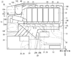
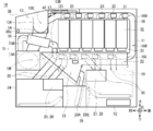
- the deposit / withdrawal unit 13 moves the shutter 13B forward and is shown in FIG.
- the coin is closed from the inside of the container 13A to the chute portion 14, lowered in the chute portion 14, and reaches the inside of the upper separation portion 15.
- the deposit / withdrawal unit 13 accommodates the coins in the container 13A and then opens the shutter 13B to the user. To receive it.
- the upper separating portion 15 is composed of an integrated separating portion 15A which is a portion occupying a relatively large volume on the lower side, and a separating and transporting portion 15B formed so as to project upward from the integrated separating portion 15A.
- the upper separation unit 15 accumulates coins in the accumulation separation unit 15A, separates the coins one by one, transports them upward by the separation transport unit 15B, and further transports the coins in the rear direction along the transport path. And hand it over to the recognition transfer unit 16.
- the recognition transport unit 16 is located on the right side of the chute unit 14, and images are taken while transporting the coin, and based on the obtained image signal, the denomination, authenticity, damage degree, etc. of the coin are used. It is determined whether or not the coin can be handled. Then, the recognition transport unit 16 notifies the coin control unit 12 of the obtained determination result as the recognition result of the coin, and delivers the coin to the delivery unit 17. The delivery unit 17 delivers the coins received from the recognition transfer unit 16 to the pin belt transfer unit 18.
- the pin belt transport unit 18 surrounds the front lower portion, the lower side, the rear side, and the upper side of the stacker portion 21 by the front pin belt transport portion 18F, the lower pin belt transport portion 18L, the rear pin belt transport portion 18R, and the upper pin belt transport portion 18U, respectively, and holds coins. It forms a transport route, which is a transport route.
- the pin belt transport unit 18 is composed of a transport guide that comes into contact with the surface of the coin and guides the coin to proceed along the transport path, and a pin belt that travels substantially along the transport path. This pin belt is provided with a pin that comes into contact with the end side of the coin and pushes it in the transport direction. By running the pin belt, the pin belt transport unit 18 transports the coins received from the delivery unit 17 along the transport path and discharges the coins into the container 13A of the deposit / withdrawal unit 13.
- the pin belt transport portion 18 is provided with branch portions 19 for branching coin transport paths at a plurality of locations in the front lower portion and the lower portion of the stacker portion 21.
- branch portions 19 for branching coin transport paths at a plurality of locations in the front lower portion and the lower portion of the stacker portion 21.
- a guide portion 30 for guiding coins is provided on the left side of each branch portion 19.
- Each branch portion 19 has a rotatable guide plate, an actuator, and the like (none of which are shown), and by rotating the guide plate under the control of the coin control unit 12, coins can be continuously rotated. It switches between advancing along the pin belt transport unit 18 and branching to each guide unit 30.
- Each guide unit 30 advances coins to the replenishment collection storage 24, the first replenishment reject storage 25 or the second replenishment reject storage 26, the temporary holding unit 23, the reject storage 27, the withdrawal storage storage 28, and the like.
- the pin belt transport portion 18 is provided with stacker branch portions 20 at six locations on the upper side of each of the six stacker portions 21.
- a guide portion 31 for guiding coins to the stacker portion 21 is provided on the left side of each stacker branch portion 20, a guide portion 31 for guiding coins to the stacker portion 21 is provided.
- Each stacker branch portion 20 is configured in the same manner as each branch portion 19, and by rotating the guide plate under the control of the coin control unit 12, whether the coin continues to advance along the pin belt transport unit 18. Or, it is switched whether to branch to each stacker unit 21.
- the stacker portion 21 is associated with coins of a predetermined denomination, respectively, and is an accumulation of a guide portion 31 provided on the upper side and a stack of coins on the lower side of the guide portion 31 so as to be stacked in the vertical direction. It has a portion 32 and a payout portion 33 for feeding coins from the lower side of the accumulating portion 32.
- the stacker section 21 receives the coins conveyed by the pin belt transport section 18 from the stacker branch section 20, the stacker section 21 guides the coins to the stacking section 32 and collects the coins. Further, the stacker unit 21, based on the control of the coin control unit 12, feeds out the coins accumulated in the accumulation unit 32 one by one by the feeding unit 33 and drops them to the lower withdrawal transport unit 22 or the temporary holding unit 23.
- the withdrawal transfer unit 22 is located on the right side of the pin belt transfer unit 18, that is, on the front side of the paper surface in FIG. 2, and is configured like a hollow rectangular parallelepiped with the upper side and the front side open, and stores coins inside. It forms the space to get. Further, the withdrawal transfer unit 22 has a belt transfer mechanism including a belt, a pulley, or the like incorporated in the bottom thereof, and coins drawn from the stacker unit 21 are placed or accumulated on the belt. The withdrawal transport unit 22 drops the coins onto the temporary holding unit 23 on the front side by running the upper portion of the belt toward the front in a state where the coins are placed or accumulated on the belt. ..
- the temporary holding portion 23 has a structure in which the bottom portion is inclined diagonally upward and forward, and the left and right side plates are shaped like a triangle. A space for accommodating coins is formed inside the temporary holding portion 23, and a belt is conveyed to the bottom portion. The mechanism is built in. Therefore, the temporary holding unit 23 places or collects the coins paid out from the stacker unit 21 and the coins conveyed from the withdrawal transfer unit 22 on the belt in the internal space. Further, the temporary holding portion 23, in a state where coins are placed or accumulated on the belt, runs the upper portion of the belt diagonally upward and forward, so that the coins are fed out to the upper separating portion 15 on the front side. , Drop it inside.
- the replenishment collection box 24 has a collecting unit for collecting coins inside, a transport mechanism for transporting the coins collected in the collecting unit, and the like.
- the replenishment collection box 24 collects the coins guided by the guide unit 30, and also pays out the coins accumulated inside and hands them over to the lower separation unit 29.
- the first replenishment reject storage 25 and the second replenishment reject storage 26 each have a space for collecting coins, and collect the coins guided by the guide unit 30.
- the reject storage 27 and the withdrawal storage 28 each have a space for collecting coins, and each of them collects the coins guided by the guide unit 30.
- the lower separation unit 29 is arranged at a position adjacent to the rear side of the replenishment collection chamber 24. Although the lower separating portion 29 has a structure similar to that of the upper separating portion 15, the mounting direction with respect to the coin processing apparatus housing 11 is different from that of the upper separating portion 15.
- the lower separation unit 29 is composed of an integration separation unit 15A and a separation / transfer unit 15B, and a corresponding accumulation / separation unit 29A and a separation / transfer unit 29B, respectively.
- the lower separation unit 29 receives coins from the replenishment collection storage 24 and accumulates them inside, separates the accumulated coins one by one, conveys them one by one upward, and discharges them into the temporary holding unit 23. ..
- the coin processing device 10 When a deposit transaction is made with a user in an automated teller machine 1 (FIG. 1), the coin processing device 10 recognizes the denomination of coins deposited in the user by the deposit counting process in the previous stage. While counting the number of coins, each coin is transported to an appropriate storage location and stored by the subsequent deposit storage process. Specifically, in the coin processing device 10 in the previous stage, when the user inserts coins into the deposit / withdrawal unit 13, the chute unit 14, the upper separation unit 15, the recognition transfer unit 16, the delivery unit 17, and the pin belt transfer The portions 18 are sequentially accommodated in the temporary holding portion 23.
- the coin processing device 10 aggregates the deposit amount based on the recognition result of each coin by the recognition transport unit 16 and displays it on the operation display unit 8 (FIG. 1), and either continues the deposit transaction to the user. Let them choose whether to cancel.
- the coin processing device 10 performs the deposit storage processing in the subsequent stage, while when cancellation is selected, the deposit transaction is canceled and the coins are processed in the same manner as in the case of the withdrawal processing described later. It is transported to the deposit / withdrawal section 13 and returned.
- the coin processing device 10 sequentially transfers coins from the temporary holding unit 23 to the upper separating unit 15, the recognition transport unit 16, the delivery unit 17, the pin belt transport unit 18, and the stacker branch unit 20 in the deposit storage process in the subsequent stage. Transport to and collect. At this time, the coin processing device 10 conveys the coins to the stacker unit 21 according to the denomination of the coins based on the recognition result of each coin by the recognition transfer unit 16.
- the coin processing device 10 deposits and withdraws coins of the amount instructed by the user by the withdrawal processing. Transport to 13 and withdraw. Specifically, when the coin processing device 10 receives from the user that a withdrawal transaction is to be started or an operation input of the withdrawal amount is received via the operation display unit 8 (FIG. 1), the coin processing device 10 starts the withdrawal process and uses the withdrawal amount. The corresponding denomination and number of coins are withdrawn from each stacker unit 21 and accumulated in the temporary holding unit 23 via the withdrawal transport unit 22. Subsequently, the coin processing device 10 transports coins to the deposit / withdrawal section 13 via the temporary holding section 23, the upper separation section 15, the recognition transport section 16, the delivery section 17, and the pin belt transport section 18 in order for use. Let someone receive it.
- the coin processing apparatus 10 includes a replenishment process for replenishing coins from the replenishment collection box 24 to the stacker section 21, a collection process for collecting coins from the stacker section 21 to the replenishment collection box 24, and the like. Can also be done.
- the left and right side plates have a substantially circular shape, and a columnar coin accumulation space 13C extending in the left-right direction and accumulating coins is formed.
- the coin accumulation plate 13D having a cross section shaped like an English capital letter "U” faces the front side, the lower side and the rear side of the coin accumulation space 13C, and the coin accumulation plate 13D has a coin accumulation plate 13D. Collect coins on the upper side.
- the rear side plate 13d which is a part of the deposit / withdrawal portion 13, located behind the coin accumulation plate 13D.
- an inclined portion 13 di inclined so that the upper side faces the rear with respect to the vertical direction is provided.
- the rear side plate 13d is provided with a shutter facing portion 13ds that bends along the horizontal direction and extends rearward from the upper end portion of the inclined portion 13di.
- a shutter facing portion groove portion 34 is engraved along the front-rear direction from the front end to the rear end at a position facing the shutter protrusion portion 13Bp (described later) of the shutter 13B at a predetermined distance in the left-right direction.
- the shutter 13B and the shutter facing portion 13ds mesh with each other in a non-contact state by the shutter protrusion portion 13Bp entering the shutter facing portion groove portion 34, and a so-called nested structure is formed in the width direction (left-right direction).
- the space between the shutter 13B and the shutter facing portion 13ds is formed narrower than the smallest coin, which is the smallest coin handled by the automated teller machine 1.
- the shutter 13B moves in the front-rear direction without contacting the shutter facing portion 13ds, and prevents coins from entering between the shutter 13B and the shutter facing portion 13ds.
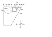
- the deposit / withdrawal unit 13 is provided with an optical hand detection sensor (not shown) that detects whether or not the user's hand is inserted in the container 13A. Therefore, as shown in FIGS. 7, 8 and 11, the inclined portion 13di of the container 13A has a sensor hole for passing the light of the hand detection sensor from the rear of the inclined portion 13di to the front side on the coin accumulation space 13C side. The portion 38 is formed.
- FIGS. 5A and 5B there is a gap between the container 13A and the storage unit 42 between the rear side plate 13d of the container 13A and the storage unit front side plate 42F (described later) of the storage unit 42.
- a gap SP2 between the reservoirs is formed.
- the gap SP between the shutter accommodating portions and the sensor hole portion 38 are collectively referred to as a space for communicating the inside and the outside of the foreign matter storage space 42S, which is a space for communicating inside and outside the accommodating portion 48 as a gap.
- the foreign matter storage portion 40 is highlighted and described in a large scale.
- the shutter 13B is provided on the lower surface of a flat plate-shaped shutter plate-shaped portion 13Bb extending in the front-rear and left-right directions, with a predetermined interval in the left-right direction, and the reservoir 13A is provided along the front-rear direction from the front end to the rear end.
- the shutter protrusion 13Bp is projected downward toward the shutter facing portion 13ds of the rear side plate 13d.
- the shutter 13B and the shutter facing portion 13ds of the container 13A mesh with each other in a non-contact state while forming a nested structure. Therefore, the space between the shutter 13B and the shutter facing portion 13ds is a small space along the front-rear direction, and the shutter accommodation is a functionally indispensable gap for the shutter 13B to move without abutting on the container 13A.
- An inter-part gap SP is formed. The gap SP between the shutter accommodating portions is formed narrower than the minimum coin.
- the foreign matter FS such as a clip, a pin, a rubber band, a piece of paper, a thread scrap, a tape or an adhesive
- the foreign matter FS becomes the coin accumulation space 13C.
- the shutter accommodating portion passes through the gap SP from the side (front side) and moves to the rear side of the rear end portion of the shutter facing portion 13ds.
- the foreign matter FS can move from the coin accumulation space 13C side (front side) to the rear side of the rear side plate 13d, that is, the outside of the coin accumulation space 13C via the sensor hole 38, in addition to the gap SP between the shutter accommodating portions. There is sex.
- a customer service portion 36 that can be opened and closed is provided at the upper end of the front end portion of the coin processing apparatus housing 11.
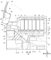
- the customer service unit 36 is clockwise or counterclockwise in FIGS. 2, 4 and 5A, and 5B with respect to the coin processing device housing 11 centered on the customer service unit rotation shaft 36a provided at the lower end of the front end thereof. It is provided so as to be rotatable around it.
- the customer service section 36 mainly incorporates a deposit / withdrawal section 13 and a foreign matter storage section 40.
- the customer service unit 36 is in the closed state of the customer service unit as shown in FIGS. 2 and 5A, thereby protecting the inside of the coin processing device housing 11 from the outside. ..
- the customer service section 36 is rotated in the opening direction, which is counterclockwise in FIG. By shifting to the open state of the customer service portion shown in 5B, the foreign matter storage portion 40 is exposed to the outside of the coin processing apparatus housing 11.
- FIGS. 5A to 13C behind the container 13A of the deposit / withdrawal section 13, the gap SP between the shutter accommodating sections or the sensor hole 38 enters, and the coin accumulation space 13C is behind the rear side plate 13d.
- a foreign matter storage unit 40 for storing the foreign matter FS that has moved to is provided.
- the foreign matter storage unit 40 is composed of a storage unit 42 and a support unit 44.
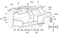
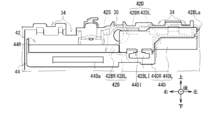
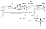
- the storage portion 42 is made of a transparent and bendable thin plate-shaped resin film such as Mylar (registered trademark), and has a substantially box-shaped shape with an open upper surface as a whole. It has a part rear side plate 42B, a storage part inner left side plate 42LR, a storage part outer left side plate 42LL, and a storage part front side plate 42F. Further, the storage section 42 includes the storage section bottom plate 42D, the storage section rear side plate 42B, the storage section inner left side plate 42LR, the storage section outer left side plate 42LL, the storage section front side plate 42F, and the support section right side plate 44R of the support section 44.
- a foreign matter storage space 42S for accommodating the foreign matter FS is formed in the enclosed space.
- the storage portion rear side plate 42B, the storage portion inner left side plate 42LR, the storage portion outer left side plate 42LL, and the storage portion front side plate 42F which are erected from the storage portion bottom plate 42D in the vertical direction, are collectively referred to as a wall portion.
- the storage unit bottom plate 42D is composed of a storage unit bottom plate right side portion 42DR and a storage unit bottom plate left side portion 42DL, and forms the bottom surface of the storage unit 42.
- the right side portion 42DR of the bottom plate of the reservoir has a rectangular shape extending in the horizontal direction and long in the left-right direction in a plan view, and has a left-right length of about two-thirds of the left-right length of the reservoir 42. , Is located to the right of the reservoir 42.
- the left side portion 42DL of the bottom plate of the storage portion extends in the horizontal direction and has a rectangular shape that is long in the left-right direction in a plan view, and has a length in the left-right direction that is about one-third of the length in the left-right direction of the storage portion 42. , It is arranged on the left side on the upper side of the right side portion 42DR of the bottom plate of the storage portion, that is, on the left side in the storage portion 42.
- the storage portion rear side plate 42B is composed of the storage portion rear side plate right side portion 42BR and the storage portion rear side plate opening / closing portion 42BL, and forms the rear side surface of the storage portion 42.
- the right side portion 42BR of the rear side plate of the storage portion is vertically bent, and is bent upward from the rear end portion of the right side portion 42DR of the bottom plate of the storage portion at a right angle to the right side portion 42DR of the bottom plate of the storage portion.
- the right side plate 42BR of the rear side plate of the storage portion has a left-right length of about two-thirds of the length of the right side portion 42DR of the bottom plate of the storage portion, and is arranged to the right of the right side portion 42DR of the bottom plate of the storage portion. There is.
- the storage section rear side plate opening / closing section 42BL as an opening / closing section is bent in the vertical direction from the rear end portion of the storage section outer left side plate 42LL, which will be described later, to the right at right angles to the storage section outer left side plate 42LL.
- the storage portion rear side plate opening / closing portion 42BL has a shape in which the uppercase letter "L” is rotated 90 degrees clockwise when viewed from the rear, and the storage portion is stored along the vertical direction, which is a connection portion with the storage portion outer left side plate 42LL.
- the rear side plate opening / closing shaft 42BLa can be rotated clockwise and counterclockwise in a plan view.
- a storage portion rear side plate opening / closing portion insertion portion 42BLI is formed at the lower end of the right end of the storage portion rear side plate opening / closing portion 42BL.
- the storage portion rear side plate opening / closing portion insertion portion 42BLI as a fixing portion has a shape in which the capital letter "T" is rotated 180 degrees when viewed from the rear, and protrudes downward.
- the storage portion rear side plate opening / closing portion insertion portion 42BLI is engaged with the storage portion rear side plate opening / closing portion insertion portion 42BLI to the insertion portion holding portion 44DI of the support portion 44.
- the foreign matter FS is stored in the storage unit 42.
- the storage section rear side plate opening / closing section insertion section 42BLI when maintenance work or the like is performed in which the foreign matter FS stored in the storage section 42 is removed, the storage section rear side plate opening / closing section insertion section 42BLI is gripped by a maintenance person. By being pulled backward, the storage part rear side plate opening / closing part insertion part 42BLI is removed from the insertion part holding part 44DI of the support part 44, and the storage part rear side plate opening / closing part 42BL axes the storage part rear side plate opening / closing shaft 42BLa.
- the portion of the storage portion rear side plate opening / closing portion 42BL in the foreign matter storage space 42S is exposed to the outside.
- the storage section rear side plate opening / closing section 42BL opens / closes the foreign matter storage space 42S.
- the left side plate 42LR inside the storage portion is vertically bent, and is bent upward from the left end portion of the right side portion 42DR of the bottom plate of the storage portion to the right angle 42DR of the bottom plate of the storage portion, and the upper end portion is stored. It is connected to the right end of the bottom plate left side 42DL.
- the storage portion outer left side plate 42LL is vertically oriented and is bent upward from the left end portion of the storage portion bottom plate left side portion 42DL at a right angle to the storage portion outer left side plate 42LL. It forms the left side.
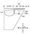
- the storage portion front side plate 42F is composed of a storage portion front side plate lower side portion 42FD and a storage portion front side plate inclined portion 42FI, and forms the front side surface of the storage portion 42.
- the lower side portion 42FD of the front side plate of the storage portion is vertically bent, and is bent upward from the rear end portion of the right side portion 42DR of the bottom plate of the storage portion at a right angle to the right side portion 42DR of the bottom plate of the storage portion.
- the storage portion front side plate lower side portion 42FD is formed from the left end portion to the right end portion of the storage portion bottom plate right side portion 42DR.
- the storage portion front plate inclined portion 42FI is inclined toward the front, which is the shutter facing portion 13ds side with respect to the vertical direction, from the upper end portion of the storage portion front side plate lower portion 42FD and the rear end portion of the storage portion bottom plate left side portion 42DL. It is bent diagonally upward and forward.
- the front end portion of the storage portion front side plate inclined portion 42FI is the storage portion front side plate inclined portion front end portion 42FIe. As shown in FIGS. 13A to 13C, the front end portion 42FIe of the inclined portion of the front side plate of the storage portion penetrates to the front side of the coin accumulation space 13C side from the lower side of the rear end portion of the shutter facing portion 13ds in the front-rear direction. ..
- the inclined portion 42FI on the front side plate of the storage portion overlaps with the rear end portion of the shutter facing portion 13ds in the front-rear direction.
- the foreign matter FS that has passed through the gap SP between the shutter storage units falls into the gap SP2 between the storage units and the storage unit 13A, which is the gap between the storage unit 42 and the storage unit 13A, in front of the storage unit 42. It can be prevented from being lost.
- the support portion 44 is formed by performing sheet metal processing such as drilling or bending in a metal plate having a predetermined thickness, and includes a support portion bottom plate 44D, a support portion right side plate 44R, a support portion left side plate 44L, and a support portion left side plate 44L. It has a support portion front side plate 44F.
- the support portion 44 is partially fixed to the container 13A and is located below the storage portion 42 as a whole to support the storage portion 42 from below and maintain the strength of the storage portion 42. There is.
- the support bottom plate 44D is composed of a support bottom plate right side 44DR and a support bottom plate left side 44DL.
- the right side portion 44DR of the bottom plate of the support portion has substantially the same outer shape as the right side portion 42DR of the bottom plate of the storage portion 42 of the storage portion 42, and is in contact with the lower surface side of the right side portion 42DR of the bottom plate of the storage portion.
- the left side portion 44DL of the bottom plate of the support portion has substantially the same outer shape as the left side portion 42DL of the bottom plate of the storage portion 42 of the storage portion 42, and is in contact with the lower surface side of the left side portion 42DL of the bottom plate of the storage portion.
- a rectangular shape of the bottom opening portion 44Da of the support portion which is long in the left-right direction in a plan view, is bored from the upper surface to the lower surface of the right side portion 44DR of the support portion bottom plate.
- the support bottom bottom opening 44Da as an opening is located slightly to the right of the support bottom plate right side 44DR, has a left-right length of about half the left-right length of the support bottom plate right side 44DR, and has a left-right length.
- the right side portion 44DR of the support portion bottom plate has a length in the front-rear direction about half of the length in the front-rear direction.
- the support portion 44 is provided with the support portion bottom surface opening 44Da having an area of about a quarter of the support portion bottom plate right portion 44DR in the support portion bottom plate right portion 44DR, thereby supporting the support portion bottom plate right portion 44DR.
- a part of the storage portion bottom plate right side portion 42DR in which the foreign matter FS is stored is exposed to the lower surface side of the support portion bottom plate right side portion 44DR via the support portion bottom surface opening 44Da.
- the foreign matter storage portion 40 makes it possible to visually recognize the foreign matter FS stored in the transparent storage portion bottom plate right side portion 42DR from the lower surface side of the support portion bottom plate right side portion 44DR via the support portion bottom surface opening 44Da.
- the insertion portion holding portion 44DI as a holding portion is formed at a position facing the insertion portion 42BLI of the storage portion rear side plate opening / closing portion of the storage portion 42.
- the support portion 44 locks the storage portion rear side plate opening / closing portion insertion portion 42BLI of the storage portion 42 with the insertion portion holding portion 44DI to close the storage portion.
- the storage portion rear side plate opening / closing portion insertion portion 42BLI of the storage portion 42 is removed from the insertion portion holding portion 44DI, and the storage portion is opened.
- the support portion right side plate 44R is along the vertical direction, and is bent upward from the right end portion of the support portion bottom plate right portion 44DR at a right angle to the support portion bottom plate right portion 44DR.
- the support portion left side plate 44L is along the vertical direction, and is bent upward from the left end portion of the support portion bottom plate right portion 44DR at a right angle to the support portion bottom plate right portion 44DR.
- the support portion left side plate 44L has substantially the same outer shape as the storage portion inner left side plate 42LR of the storage portion 42, and is in contact with the left surface side of the storage portion inner left side plate 42LR.
- the support portion front side plate 44F is along the vertical direction, and is bent upward from the right side of the front end portion of the support portion bottom plate right side portion 44DR at a right angle to the support portion bottom plate right portion 44DR.
- the length of the support portion front plate 44F is slightly shorter in the vertical direction than the length of the reservoir front plate lower portion 42FD of the reservoir 42, and the length in the left-right direction is about half of the length in the left-right direction of the support portion bottom plate right portion 44DR. Has a length of.
- the support portion front side plate 44F is in contact with the front surface side of the storage portion front side plate lower side portion 42FD of the storage portion 42.
- the lower surface of the rectangular double-sided tape 46 is attached to the left and right ends of the support bottom plate right side 44DR and the left end of the support bottom plate left side 44DL.
- the right side portion 42DR of the bottom plate of the storage portion and the left side portion 42DL of the bottom plate of the storage portion in the storage portion 42 are attached to the upper surface of the double-sided tape 46. Therefore, the storage portion 42 is attached and fixed to the upper side of the support portion 44 by the double-sided tape 46.
- the maintenance staff picks the storage part rear side plate opening / closing part insertion part 42BLI of the storage part rear side plate opening / closing part 42BL in the storage part 42 with a finger and moves it backward, so that the storage part rear side plate opening / closing part insertion part 42BLI. Is removed from the insertion part holding part 44DI. Furthermore, the maintenance staff continues to pick up the storage section rear side plate opening / closing section insertion section 42BLI with his fingers and move it backward, so that the storage section rear side plate opening / closing section 42BL can be moved around the storage section rear side plate opening / closing shaft 42BLa as an opening / closing axis.
- the portion of the storage portion rear side plate opening / closing portion 42BL in the foreign matter storage space 42S is exposed to the outside, and the finger or tweezers of the maintenance staff reaches the foreign matter storage space 42S.
- the maintenance staff collects the foreign matter FS by picking and removing the foreign matter FS in the foreign matter storage space 42S with a finger or tweezers.
- the coin processing device 10 is provided with a foreign matter storage unit 40 so as to be adjacent to the container 13A on the rear side where the shutter 13B is located in the shutter open state, rather than the container 13A. Therefore, the coin processing device 10 can store the foreign matter FS that has entered the gap SP between the shutter accommodating portions and the sensor hole portion 38 from the coin accumulation space 13C by the foreign matter storage portion 40. As a result, the coin processing device 10 prevents foreign matter FS from entering each part inside the coin processing device 10, thereby preventing factors of miscalculation and imposing a load on the driving part, and improving reliability. Can be made to.
- the storage portion rear side plate opening / closing portion insertion portion 42BLI of the storage portion rear side plate opening / closing portion 42BL which is a part of the wall portion of the storage portion 42, can be attached to and detached from the insertion portion holding portion 44DI. Therefore, the coin processing device 10 inserts the storage section rear side plate opening / closing section insertion section 42BLI of the storage section rear side plate opening / closing section 42BL without forcing the maintenance staff to perform the complicated operation of removing the entire storage section 42 from the support section 44.
- the foreign matter FS stored in the foreign matter storage space 42S can be removed by the maintenance staff through the space in which the storage section rear side plate opening / closing section 42BL is retracted simply by removing it from the recessing section holding section 44DI and opening the storage section.
- the coin processing device 10 can easily collect the foreign matter FS by the maintenance staff, and can improve the workability of removing the foreign matter.
- the storage unit 42 of the foreign matter storage unit 40 is made of a transparent member. Therefore, the foreign matter storage unit 40 can visualize the foreign matter storage space 42S of the storage unit 42 from the outside of the storage unit 42, and can visually recognize the foreign matter FS stored in the storage unit 42 from the outside of the storage unit 42.
- the coin processing device 10 is provided with a support portion bottom opening 44Da in the support portion bottom plate right side portion 44DR facing the storage portion bottom plate right portion 42DR of the storage portion 42. Therefore, the foreign matter storage unit 40 stores the foreign matter storage space 42S of the storage unit 42 from the direction of the arrow AR1 via the support portion bottom opening 44Da as shown in FIG. 11 in the customer service unit open state shown in FIG. 5B. It can be made visible from the outside of the portion 42.
- the coin processing device 10 has a deposit / withdrawal unit 13 having a container 13A as a loading unit into which coins as a medium are inserted, a shutter 13B for opening / closing the container 13A, and a deposit / withdrawal unit 13.
- a foreign matter storage section 40 is provided on the opposite side of the container 13A with the accommodation section internal / external communication space 48 as a gap formed in the accommodation section in between, and a foreign matter storage section 40 for storing foreign matter FS that has entered from the accommodation section internal / external communication space 48. ..
- the coin processing device 10 can store the foreign matter FS that has entered the inside / outside communication space 48 of the accommodating portion from the coin accumulation space 13C by the foreign matter storage unit 40, and the foreign matter FS enters each part inside the coin processing device 10. It can be prevented from being stored.
- the foreign matter storage unit 140 As shown in FIGS. 14A and 14B in which the members corresponding to those in FIGS. 5A and 5B are designated by the same reference numerals, the foreign matter storage unit 140 according to the other embodiment is in the storage unit 42 as compared with the foreign matter storage unit 40. Although different in that it has an alternative reservoir 142, it is configured similarly in other respects.
- the storage unit 142 differs from the storage unit 42 in that it has a storage unit rear side plate 142B that replaces the storage unit rear side plate 42B and a storage unit bottom plate 142D that replaces the storage unit bottom plate 42D, but other points. Is configured in the same way.
- the storage portion rear side plate 142B is not provided with the storage portion rear side plate opening / closing portion 42BL, and the storage portion rear side plate bottom plate which is a connection portion between the storage portion rear side plate 142B and the storage portion bottom plate 142D with respect to the storage portion rear side plate 142B. It is rotatable clockwise and counterclockwise with respect to the bottom plate 142D of the storage portion with the connecting portion 42Bax as an axis.
- the storage unit 142 is a coin processing device other than the customer service unit 36, in which the storage unit rear side plate bottom plate connection portion 42Bax does not move together with the customer service unit 36 when transitioning between the customer service unit closed state and the customer service unit open state. It is connected to the housing 11 by a link mechanism (not shown).
- the storage unit 142 has the same shape as the storage unit 42 (FIG. 5A) in the closed state of the customer service unit (FIG. 14A). On the other hand, when the storage unit 142 transitions from the customer service unit closed state (FIG. 14A) to the customer service unit open state (FIG.
- the storage unit rear side plate 142B is pulled backward by the link mechanism, so that the storage unit rear side plate 142B However, the upper end is inclined toward the rear in the vertical direction. In this state, the rear side plate 142B of the storage portion retracts to the rear, and the rear side surface of the foreign matter storage space 42S is largely exposed to the outside.
- the above-mentioned storage unit 42 rotated together with the customer service unit 36 without deforming the entire storage unit 42 as the customer service unit 36 rotated.
- the front side plate 42F of the storage unit and the bottom plate 142D of the storage unit rotate together with the customer service unit 36 as the customer service unit 36 rotates, but the rear side plate 142B of the storage unit rotates together with the customer service unit 36.
- the foreign matter storage space 42S is largely exposed to the outside and opened.
- the rear side plate 142B of the storage unit rotates with respect to the bottom plate 142D of the storage unit only by rotating the customer service unit 36, and the foreign matter storage unit 140 rotates the rear side surface of the foreign matter storage space 42S.
- the foreign matter FS stored in the storage portion 142 can be visually recognized from the outside of the storage portion 142, and the foreign matter FS can be removed without having the maintenance staff perform the operation of opening and closing the rear side plate opening / closing portion 42BL of the storage portion. It can be collected.
- the maintenance staff When removing the foreign matter FS stored in the foreign matter storage unit 140, the maintenance staff first rotates the customer service unit 36 from the closed state of the customer service unit in FIG. 14A to the open state of the customer service unit in FIG. 14B, thereby causing the foreign matter storage unit 140. Make it accessible to. At this time, the storage unit 142 largely exposes the rear side surface of the foreign matter storage space 42S to the outside by pulling the rear side plate 142B of the storage unit rearward by the link mechanism. In this open state of the customer service section, the maintenance staff visually inspects the foreign matter storage space 42S of the storage section 142 from the direction of the arrow AR2, and confirms whether or not the foreign matter FS is stored inside the foreign matter storage section 140. Subsequently, the maintenance staff collects the foreign matter FS by picking and removing the foreign matter FS in the foreign matter storage space 42S from the rear side plate 142B of the storage portion with a finger or tweezers.
- the storage unit 142 interlocks the opening / closing operation of the customer service unit 36 with the opening / closing of the storage unit rear side plate 142B, and when the customer service unit 36 rotates from the customer service unit closed state to the customer service unit open state, the customer service unit 36
- the rear side plate 142B of the storage portion is rotated with respect to the bottom plate 142D of the storage portion so as to be separated from the foreign matter storage space 42S.
- the storage unit 142 only causes the maintenance personnel to perform an operation of rotating the customer service unit 36 from the customer service unit closed state to the customer service unit open state, which is an operation that is indispensable when accessing the foreign matter storage unit 140. Therefore, the rear side surface of the foreign matter storage space 42S can be exposed so that the foreign matter FS stored in the storage portion 142 can be visually recognized from the outside of the storage portion 142 and the foreign matter FS can be collected.
- the storage unit 142 can further improve the visibility of the foreign matter FS inside the foreign matter storage unit 140 from the outside as compared with the coin processing device 10, and can further improve the ease of collecting the foreign matter FS.
- the foreign matter storage unit 140 can exert the same action and effect as the foreign matter storage unit 40.
- the support portion bottom surface opening 44Da has a rectangular shape long in the left-right direction in a plan view has been described.
- the present invention is not limited to this, and the support bottom bottom opening 44Da may have various shapes such as a triangular shape, a square shape, a circular shape, and an elliptical shape in a plan view.
- the foreign matter FS that has entered the gap SP between the shutter housing portions, which is the gap between the container 13A and the shutter 13B, and the sensor hole 38 formed in the container 13A itself is stored.
- the case where the present invention is applied to the foreign matter storage unit 40 has been described.
- the present invention is not limited to this, and the present invention is applied to various other places where an indispensable gap exists, such as a stacker for accumulating coins for each type of coin, which has a hole for a sensor and a transport path. May be.
- the present invention is not limited to the above-described embodiments and other embodiments. That is, the present invention has an applicable scope to an embodiment in which each of the above-described embodiments and a part or all of the above-mentioned other embodiments are arbitrarily combined, and an embodiment in which a part is extracted. Is.
- the present invention can be used, for example, in an automated teller machine that processes transactions related to coins with a user.
Landscapes
- Physics & Mathematics (AREA)
- General Physics & Mathematics (AREA)
- Control Of Vending Devices And Auxiliary Devices For Vending Devices (AREA)
- Financial Or Insurance-Related Operations Such As Payment And Settlement (AREA)
Abstract
【課題】信頼性を保つ。 【解決手段】現金自動預払機1の硬貨処理装置10は、硬貨が投入される収容器13Aと、収容器13Aを開閉するシャッタ13Bとを有する入出金部13と、入出金部13に形成された収容部内外連通空間48を挟んで収容器13Aの反対側に配置され、収容部内外連通空間48から入り込んだ異物FSを貯留する異物貯留部40とを設ける。
Description
本発明は媒体処理装置及び現金取扱装置に関し、例えば使用者に紙幣や硬貨を投入させて所望の取引を行う現金自動預払機(ATM:Automatic Teller Machine)に適用して好適なものである。
従来、金融機関等で使用される現金自動預払機等においては、使用者との取引内容に応じて、例えば使用者に紙幣や硬貨等の現金を入金させ、また使用者へ現金を出金するものが広く普及している。この現金自動預払機としては、例えば硬貨に関する処理を行う媒体処理装置を内部に有するものがある。媒体処理装置は、例えば使用者との間で硬貨の授受を行う入出金部、集積された硬貨を1枚ずつに分離する分離部、硬貨を搬送する搬送部、投入された硬貨の金種や真偽等を識別する識別部(認識部とも呼ぶ)、及び金種毎に硬貨を収納する収納部等を有している。
このような媒体処理装置においては、入出金部において、該入出金部内の硬貨や異物等を検出する光学式のセンサが設けられているものがある。また入出金部では、センサの光を通過させる、機能上必要不可欠なセンサ用孔部が適宜形成されている(例えば、特許文献1参照)。
しかしながら、そのようなセンサ用孔部等の隙間を介し、入出金部から媒体処理装置内部に異物が入り込むことがある。その結果、違算の要因となったり、駆動部に負荷を与え停止させる要因になったりしてしまい、信頼性が保てない可能性があった。
本発明は以上の点を考慮してなされたもので、信頼性を保ち得る媒体処理装置及び現金取扱装置を提案しようとするものである。
かかる課題を解決するため本発明の媒体処理装置においては、媒体が投入される投入部と、投入部を開閉するシャッタとを有する入出金部と、入出金部に形成された隙間を挟んで投入部の反対側に配置され、隙間から入り込んだ異物を貯留する異物貯留部とを設けるようにした。
また本発明の現金取扱装置においては、使用者の操作を受け付ける操作部と、上述した媒体処理装置とを設けるようにした。
本発明は、媒体を貯留する空間から隙間に入り込んだ異物を異物貯留部によって貯留することができ、該異物が媒体処理装置内部の各部に入り込んでしまうことを防止できる。
本発明によれば、信頼性を保ち得る媒体処理装置及び現金取扱装置を実現できる。
以下、発明を実施するための形態(以下実施の形態とする)について、図面を用いて説明する。
[1.現金自動預払機の構成]
図1に外観を示すように、現金取扱装置としての現金自動預払機1は、箱状の筐体2を中心に構成されており、例えば金融機関や各種商業施設等に設置され、使用者(すなわち金融機関や商業施設の顧客等)との間で、入金処理や出金処理等の現金に関する取引を行う。
図1に外観を示すように、現金取扱装置としての現金自動預払機1は、箱状の筐体2を中心に構成されており、例えば金融機関や各種商業施設等に設置され、使用者(すなわち金融機関や商業施設の顧客等)との間で、入金処理や出金処理等の現金に関する取引を行う。
筐体2は、その前側に使用者が対峙した状態で紙幣の投入やタッチパネルによる操作等をしやすい箇所に応対部3が設けられている。応対部3は、通帳入出口4、カード入出口5、硬貨入出金口6、紙幣入出金口7及び操作表示部8等が設けられており、使用者との間で例えば現金やカード等を直接やり取りすると共に、取引に関する情報の通知や操作指示の受付を行う。
通帳入出口4は、通帳が挿入され、また排出する部分である。通帳入出口4の奥側には、通帳の裏表紙等に設けられた磁気記録部から磁気情報を読み取り、また該通帳に取引の内容を記録する通帳処理部(図示せず)が設けられている。カード入出口5は、キャッシュカード等の各種カードが挿入又は排出される部分である。カード入出口5の奥側には、各種カードに磁気記録された口座番号等の読み取りを行うカード処理部(図示せず)が設けられている。
硬貨入出金口6は、使用者によって入金される硬貨が投入されると共に、使用者へ出金する硬貨が排出される部分である。紙幣入出金口7は、使用者によって入金される紙幣が投入されると共に、使用者へ出金する紙幣が排出される部分である。この硬貨入出金口6及び紙幣入出金口7は、それぞれシャッタを駆動することにより開放又は閉塞する。操作部としての操作表示部8は、取引に際して操作画面や取引内容等を表示する液晶表示パネルと、使用者の入力操作を検知するタッチセンサとが一体化されたタッチパネルである。
以下では、現金自動預払機1のうち使用者が対峙する側を前側とし、その反対を後側とし、該前側に対峙した使用者から見て左及び右をそれぞれ左側及び右側とし、さらに上側及び下側を定義して説明する。
筐体2の内部には、現金自動預払機1全体を統括制御する主制御部9や、取引対象である硬貨に関する種々の処理を行う硬貨処理装置10、及び紙幣に関する種々の処理を行う紙幣処理装置(図示せず)等が設けられている。主制御部9は、図示しないCPU(Central Processing Unit)を中心に構成されており、図示しないROM(Read Only Memory)やフラッシュメモリ等から所定のプログラムを読み出して実行することにより、入金処理や出金処理等の種々の処理を行う。また主制御部9は、内部にRAM(Random Access Memory)、ハードディスクドライブやフラッシュメモリ等でなる記憶部を有しており、この記憶部に種々の情報を記憶させる。
硬貨処理装置10は、全体として直方体に類似した形状に構成されており、図示しないスライドレールを介して筐体2に取り付けられている。また筐体2の前面側又は後面側には、開閉可能な扉(図示せず)が設けられている。このため現金自動預払機1は、保守作業等が行われる場合、筐体2の前面側又は後面側の扉を開放した上で、硬貨処理装置10を前方又は後方へスライドさせることにより、該硬貨処理装置10を該筐体2の外部に位置させ、また該筐体2の内部に収納させる。
[2.硬貨処理装置の構成]
硬貨処理装置10は、図2に模式的な右側面図を示すように、硬貨処理装置筐体11の内部に、硬貨に関する種々の処理を行う複数の部分が組み込まれている。この硬貨は、例えば銅及びニッケルの合金やアルミニウム等、十分な強度を有する非磁性体の材料でなり、薄い板状に形成されている。因みに硬貨処理装置10では、直径や厚さが異なる複数種類の硬貨を取り扱うことが想定されている。
硬貨処理装置10は、図2に模式的な右側面図を示すように、硬貨処理装置筐体11の内部に、硬貨に関する種々の処理を行う複数の部分が組み込まれている。この硬貨は、例えば銅及びニッケルの合金やアルミニウム等、十分な強度を有する非磁性体の材料でなり、薄い板状に形成されている。因みに硬貨処理装置10では、直径や厚さが異なる複数種類の硬貨を取り扱うことが想定されている。
硬貨処理装置筐体11の内部には、比較的上側ないし中央付近に、入出金部13、シュート部14、上分離部15、認識搬送部16、受渡部17、ピンベルト搬送部18、6個のスタッカ部21、出金搬送部22及び一時保留部23が設けられている。また硬貨処理装置筐体11の内部には、比較的下側に、硬貨制御部12、補充回収庫24、第1補充リジェクト庫25、第2補充リジェクト庫26、リジェクト庫27、取忘取込庫28及び下分離部29が設けられている。
硬貨制御部12は、主制御部9と同様、図示しないCPUを中心に構成されており、図示しないROMやフラッシュメモリ等から所定のプログラムを読み出して実行することにより、入金取引や出金取引等に関する種々の処理を行い、硬貨処理装置10を統括制御する。また硬貨制御部12は、内部にRAM及びフラッシュメモリ等でなる記憶部を有しており、この記憶部に種々の情報を記憶させる。
入出金部13は、使用者との間で硬貨を受け渡すことにより、該使用者に硬貨を入金させ、又は該使用者に硬貨を出金する。該入出金部13は、上側に開口部を有し硬貨を収容する収容器13A、該開口部を開閉するシャッタ13B等、及び収容器13A内における硬貨の有無等を検知するセンサ(図示せず)を有している。
入出金部13は、シャッタ13Bを図3に示すように後方へスライド移動させて開放した状態で使用者により硬貨が収容器13Aに投入されると、該シャッタ13Bを前方へ移動させて図2に示すように閉塞し、硬貨を収容器13A内からシュート部14に引き渡して該シュート部14内を下降させ、上分離部15内に到達させる。また入出金部13は、シャッタ13Bを閉塞した状態で、後述するピンベルト搬送部18から硬貨が搬送されてくると、該硬貨を収容器13A内に収容した後、シャッタ13Bを開放して使用者に受け取らせる。
上分離部15は、下側の比較的大きい容積を占める部分である集積分離部15Aと、該集積分離部15Aから上方に突出するように形成された分離搬送部15Bとにより構成されている。この上分離部15は、集積分離部15Aに硬貨を集積すると共に、この硬貨を1枚ずつに分離して分離搬送部15Bにより上方向へ搬送し、さらに搬送路に沿って後方向へ搬送して認識搬送部16に引き渡す。
認識搬送部16は、シュート部14の右側に位置しており、硬貨を搬送しながら撮像し、得られた画像信号を基に該硬貨の金種や真偽、或いは損傷の程度等を基に該硬貨が取扱可能であるか否かを判定する。そのうえで認識搬送部16は、得られた判定結果を該硬貨の認識結果として硬貨制御部12に通知すると共に、該硬貨を受渡部17に引き渡す。受渡部17は、認識搬送部16から受け取った硬貨をピンベルト搬送部18に引き渡す。
ピンベルト搬送部18は、スタッカ部21の前側下部、下側、後側及び上側をそれぞれ前ピンベルト搬送部18F、下ピンベルト搬送部18L、後ピンベルト搬送部18R及び上ピンベルト搬送部18Uにより取り囲み、硬貨を搬送する経路である搬送経路を形成している。ピンベルト搬送部18は、硬貨の盤面と当接し搬送経路に沿って進行するよう案内する搬送ガイドと、概ね該搬送経路に沿って走行するピンベルトとにより構成されている。このピンベルトには、硬貨の末尾側と当接し、搬送方向へ押動するためのピンが設けられている。ピンベルト搬送部18は、ピンベルトを走行させることにより、受渡部17から受け取った硬貨を搬送経路に沿って搬送し、入出金部13の収容器13A内へ放出する。
またピンベルト搬送部18には、スタッカ部21の前側下部及び下側に配置された部分における複数箇所に、硬貨の搬送経路を分岐させる分岐部19がそれぞれ設けられている。各分岐部19の左側には、硬貨を案内する案内部30がそれぞれ設けられている。
各分岐部19は、それぞれ回動可能な案内板及びアクチュエータ等(何れも図示せず)を有しており、硬貨制御部12の制御に基づいて案内板を回動させることにより、硬貨を引き続きピンベルト搬送部18に沿って進行させるか、或いは各案内部30へ分岐させるかを切り替える。各案内部30は、それぞれ補充回収庫24、第1補充リジェクト庫25又は第2補充リジェクト庫26、一時保留部23、リジェクト庫27及び取忘取込庫28等へ硬貨を進行させる。
さらにピンベルト搬送部18には、6個のスタッカ部21のそれぞれ上側となる6箇所に、スタッカ分岐部20が設けられている。各スタッカ分岐部20の左側には、硬貨をスタッカ部21へ案内する案内部31が設けられている。各スタッカ分岐部20は、各分岐部19と同様に構成されており、硬貨制御部12の制御に基づいて案内板を回動させることにより、硬貨を引き続きピンベルト搬送部18に沿って進行させるか、或いは各スタッカ部21へ分岐させるかを切り替える。
スタッカ部21は、それぞれ所定の金種の硬貨と対応付けられており、上側に設けられた案内部31と、該案内部31の下側において硬貨を上下方向に沿って積み重ねるように集積する集積部32と、該集積部32の下側から硬貨を繰り出す繰出部33とを有している。このスタッカ部21は、ピンベルト搬送部18により搬送された硬貨をスタッカ分岐部20から受け取ると、該硬貨を案内部31により集積部32へ案内して集積させる。またスタッカ部21は、硬貨制御部12の制御に基づき、集積部32に集積している硬貨を繰出部33により1枚ずつ繰り出し、下方の出金搬送部22又は一時保留部23へ落下させる。
出金搬送部22は、ピンベルト搬送部18の右側、すなわち図2における紙面の手前側に位置しており、上側及び前側が開放された中空の直方体のように構成され、内部に硬貨を収容し得る空間を形成している。また出金搬送部22は、底部にベルトやプーリ等でなるベルト搬送機構が組み込まれており、スタッカ部21から繰り出された硬貨をベルト上に載置若しくは集積する。この出金搬送部22は、ベルトの上に硬貨が載置若しくは集積された状態で、該ベルトの上側部分を前方へ向けて走行させることにより、該硬貨を前側の一時保留部23へ落下させる。
一時保留部23は、底部が前斜め上方へ向かって傾斜し、左右の側板を三角形状としたような構成となっており、その内部に硬貨を収容する空間を形成すると共に、底部にベルト搬送機構が組み込まれている。このため一時保留部23は、スタッカ部21から繰り出された硬貨や出金搬送部22から搬送されてきた硬貨を、内部空間のベルト上に載置若しくは集積させる。また一時保留部23は、ベルトの上に硬貨が載置若しくは集積された状態で、該ベルトの上側部分を前斜め上方へ向けて走行させることにより、該硬貨を前側の上分離部15へ繰り出し、その内部へ落下させる。
補充回収庫24は、内部に硬貨を集積する集積部や、該集積部に集積されている硬貨を搬送する搬送機構等を有している。この補充回収庫24は、案内部30により案内されてきた硬貨を集積し、また内部に集積している硬貨を前方へ繰り出して下分離部29に引き渡す。第1補充リジェクト庫25及び第2補充リジェクト庫26は、それぞれ内部に硬貨を集積する空間を有しており、案内部30により案内されてきた硬貨を集積する。リジェクト庫27及び取忘取込庫28は、それぞれ内部に硬貨を集積する空間を有しており、案内部30により案内されてきた硬貨をそれぞれ集積する。
下分離部29は、補充回収庫24の後側に隣接する位置に配置されている。この下分離部29は、上分離部15と類似した構成となっているものの、硬貨処理装置筐体11に対する取付方向が、該上分離部15とは相違している。この下分離部29は、集積分離部15A及び分離搬送部15Bとそれぞれ対応する集積分離部29A及び分離搬送部29Bにより構成されている。下分離部29は、補充回収庫24から硬貨を受け取って内部に集積し、また集積されている硬貨を1枚ずつに分離して1枚ずつ上方へ搬送し、一時保留部23内へ放出する。
[3.各種処理における硬貨の搬送]
次に、硬貨処理装置10において硬貨の搬送を伴う種々の処理、すなわち入金処理及び出金処理等における硬貨の搬送や集積等について説明する。ここでは、現金自動預払機1と使用者との間で入金取引及び出金取引を行う場合における硬貨処理装置10での各処理についてそれぞれ説明する。
次に、硬貨処理装置10において硬貨の搬送を伴う種々の処理、すなわち入金処理及び出金処理等における硬貨の搬送や集積等について説明する。ここでは、現金自動預払機1と使用者との間で入金取引及び出金取引を行う場合における硬貨処理装置10での各処理についてそれぞれ説明する。
現金自動預払機1(図1)において使用者との間で入金取引が行われる場合、硬貨処理装置10は、前段の入金計数処理により、使用者に入金された硬貨の金種等を認識しながら枚数を計数し、これに続く後段の入金収納処理により、各硬貨を適切な収納箇所へ搬送して収納する。具体的に硬貨処理装置10は、前段の入金計数処理において、使用者に入出金部13に硬貨を投入させると、シュート部14、上分離部15、認識搬送部16、受渡部17及びピンベルト搬送部18を順次介して一時保留部23に収容する。
このとき硬貨処理装置10は、認識搬送部16による各硬貨の認識結果を基に入金額を集計して操作表示部8(図1)に表示し、使用者に入金取引を継続するか、又は中止するかを選択させる。硬貨処理装置10は、使用者により継続が選択されると、後段の入金収納処理を行う一方、中止が選択されると、入金取引を中止し、後述する出金処理の場合と同様に硬貨を入出金部13へ搬送して返却する。
硬貨処理装置10は、後段の入金収納処理において、硬貨を一時保留部23から上分離部15、認識搬送部16、受渡部17、ピンベルト搬送部18及びスタッカ分岐部20を順次介してスタッカ部21へ搬送して集積させる。このとき硬貨処理装置10は、認識搬送部16による各硬貨の認識結果を基に、該硬貨の金種に応じたスタッカ部21へ搬送する。
また、現金自動預払機1(図1)において使用者との間で出金取引が行われる場合、硬貨処理装置10は、出金処理により、使用者に指示された金額の硬貨を入出金部13へ搬送して出金する。具体的に硬貨処理装置10は、操作表示部8(図1)を介して使用者から出金取引を開始する旨や出金額の操作入力を受け付けると、出金処理を開始し、出金額に応じた硬貨の金種及び枚数を各スタッカ部21から出金させ、出金搬送部22を介して一時保留部23内に集積させる。続いて硬貨処理装置10は、一時保留部23、上分離部15、認識搬送部16、受渡部17及びピンベルト搬送部18を順次経由して硬貨を入出金部13へ搬送して収容させ、使用者に受け取らせる。
因みに硬貨処理装置10は、入金処理及び出金処理の他、補充回収庫24からスタッカ部21へ硬貨を補充する補充処理や、該スタッカ部21から補充回収庫24へ硬貨を回収する回収処理等も行い得るようになっている。
[4.入出金部の構成]
[4-1.収容器の構成]
図6に示すように収容器13Aは、左右の側板が略円形状であり、左右方向に沿って延び硬貨を集積する円柱形状の硬貨集積空間13Cが形成されている。また収容器13Aは、横断面が英大文字の「U」のような形状の硬貨集積板13Dが、硬貨集積空間13Cの前側、下側及び後側と対向しており、該硬貨集積板13Dの上側に硬貨を集積させる。
[4-1.収容器の構成]
図6に示すように収容器13Aは、左右の側板が略円形状であり、左右方向に沿って延び硬貨を集積する円柱形状の硬貨集積空間13Cが形成されている。また収容器13Aは、横断面が英大文字の「U」のような形状の硬貨集積板13Dが、硬貨集積空間13Cの前側、下側及び後側と対向しており、該硬貨集積板13Dの上側に硬貨を集積させる。
図6、図7、図8、図9、図10、図11及び図13A~図13Cに示すように、硬貨集積板13Dの後側に位置する、入出金部13の一部分である後側板13dの上端部近傍は、鉛直方向に対し上側が後方へ向かうよう傾斜した傾斜部13diが設けられている。
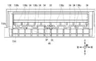
また後側板13dは、傾斜部13diの上端部から、水平方向に沿うように屈曲し後方へ向かって延在するシャッタ対向部13dsが設けられている。シャッタ対向部13dsは、シャッタ13Bのシャッタ突起部13Bp(後述する)と対向する箇所において、左右方向に所定の間隔を空けて前端から後端まで前後方向に沿ったシャッタ対向部溝部34が刻設されている。これによりシャッタ13Bとシャッタ対向部13dsとは、シャッタ対向部溝部34にシャッタ突起部13Bpが入り込むことにより非接触状態で噛み合い、いわゆる入れ子構造が幅方向(左右方向)に亘って形成されている。シャッタ13Bとシャッタ対向部13dsとの間は、現金自動預払機1において取り扱われる硬貨のうち最もサイズが小さい硬貨である最小硬貨よりも狭く形成されている。これによりシャッタ13Bは、シャッタ対向部13dsに接触することなく前後方向に移動すると共に、シャッタ13Bとシャッタ対向部13dsとの間に硬貨が侵入することを防止している。
さらに入出金部13には、収容器13A内に使用者の手が挿入されているかを検知する光学式の手検出センサ(図示せず)が設けられている。このため図7、図8及び図11に示すように収容器13Aの傾斜部13diには、手検出センサの光を傾斜部13diの後方から硬貨集積空間13C側である前側へ通過させるセンサ用孔部38が形成されている。
また図5A、図5Bに示すように、収容器13Aの後側板13dと貯留部42の貯留部前側板42F(後述する)との間には、収容器13Aと貯留部42との隙間である貯留部収容器間隙間SP2が形成されている。以下では、シャッタ収容部間隙間SPとセンサ用孔部38とをまとめて、異物貯留空間42Sの内部と外部とを連通させる空間である、隙間としての収容部内外連通空間48とも呼ぶ。なお図5A、図5B及び図14A、図14Bにおいては、異物貯留部40を強調して大きく記載している。
[4-2.シャッタの構成]
図7に示すようにシャッタ13Bは、前後左右方向に伸びる平板形状のシャッタ板状部13Bbの下面において、左右方向に所定の間隔を空けて、前端から後端まで前後方向に沿って収容器13Aにおける後側板13dのシャッタ対向部13dsに向かって下方向へシャッタ突起部13Bpが突設されている。
図7に示すようにシャッタ13Bは、前後左右方向に伸びる平板形状のシャッタ板状部13Bbの下面において、左右方向に所定の間隔を空けて、前端から後端まで前後方向に沿って収容器13Aにおける後側板13dのシャッタ対向部13dsに向かって下方向へシャッタ突起部13Bpが突設されている。
このようにシャッタ13Bと収容器13Aのシャッタ対向部13dsとは、入れ子構造を形成しつつ、非接触状態で噛み合っている。このためシャッタ13Bとシャッタ対向部13dsとの間には、前後方向に沿う僅かな空間であり、シャッタ13Bが収容器13Aに当接せず移動するために機能上必要不可欠な隙間であるシャッタ収容部間隙間SPが形成されている。このシャッタ収容部間隙間SPは、最小硬貨よりも狭く形成されている。しかしながら収容器13Aに対し、正規の硬貨の他に、クリップ、ピン、輪ゴム、紙切れ、糸屑、テープや粘着物等の異物FSが一緒に投入されると、該異物FSが、硬貨集積空間13C側(前側)からシャッタ収容部間隙間SPを通過し、シャッタ対向部13dsの後端部よりも後側まで移動する可能性がある。
また異物FSは、シャッタ収容部間隙間SP以外にも、センサ用孔部38を介して硬貨集積空間13C側(前側)から後側板13dの後側、すなわち硬貨集積空間13Cの外部まで移動する可能性がある。
[5.接客部の構成]
図2及び図4に示すように硬貨処理装置筐体11における前端部の上端には、開閉可能な接客部36が設けられている。接客部36は、硬貨処理装置筐体11に対し、その前端下端部に設けられた接客部回動軸36aを中心として、図2、図4及び図5A、図5B中で時計回り又は反時計回りに回動可能に設けられている。この接客部36には、主に、入出金部13及び異物貯留部40が組み込まれている。
図2及び図4に示すように硬貨処理装置筐体11における前端部の上端には、開閉可能な接客部36が設けられている。接客部36は、硬貨処理装置筐体11に対し、その前端下端部に設けられた接客部回動軸36aを中心として、図2、図4及び図5A、図5B中で時計回り又は反時計回りに回動可能に設けられている。この接客部36には、主に、入出金部13及び異物貯留部40が組み込まれている。
このため硬貨処理装置10は、通常の動作時の場合、接客部36が図2及び図5Aに示すように接客部閉鎖状態になることにより、硬貨処理装置筐体11の内部を外部から保護する。一方硬貨処理装置10は、異物貯留部40に貯留した異物FSが取り除かれる保守作業等が行われる場合、接客部36が図4中反時計回りである開放方向へ回動されて図4及び図5Bに示す接客部開放状態に移行することにより、異物貯留部40を硬貨処理装置筐体11の外部に露出させる。
[6.異物貯留部の構成]
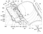
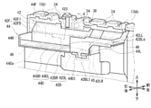
図5A~図13Cに示すように、入出金部13の収容器13Aの後方には、シャッタ収容部間隙間SP又はセンサ用孔部38に入り込み硬貨集積空間13C側から後側板13dよりも後側まで移動した異物FSを貯留する異物貯留部40が設けられている。異物貯留部40は、貯留部42及び支持部44により構成されている。
図5A~図13Cに示すように、入出金部13の収容器13Aの後方には、シャッタ収容部間隙間SP又はセンサ用孔部38に入り込み硬貨集積空間13C側から後側板13dよりも後側まで移動した異物FSを貯留する異物貯留部40が設けられている。異物貯留部40は、貯留部42及び支持部44により構成されている。
[6-1.貯留部の構成]
貯留部42は、例えばマイラー(登録商標)等の、透明で折り曲げ可能な薄板状の樹脂フィルムにより構成されており、全体として上面が開放された略箱型形状であり、貯留部底板42D、貯留部後側板42B、貯留部内側左側板42LR、貯留部外側左側板42LL及び貯留部前側板42Fを有している。また貯留部42は、これら貯留部底板42D、貯留部後側板42B、貯留部内側左側板42LR、貯留部外側左側板42LL及び貯留部前側板42Fと、支持部44の支持部右側板44Rとに囲まれた空間に、異物FSを収容する異物貯留空間42Sが形成されている。以下では、貯留部底板42Dから鉛直方向に沿って立設する貯留部後側板42B、貯留部内側左側板42LR、貯留部外側左側板42LL及び貯留部前側板42Fをまとめて、壁部とも呼ぶ。
貯留部42は、例えばマイラー(登録商標)等の、透明で折り曲げ可能な薄板状の樹脂フィルムにより構成されており、全体として上面が開放された略箱型形状であり、貯留部底板42D、貯留部後側板42B、貯留部内側左側板42LR、貯留部外側左側板42LL及び貯留部前側板42Fを有している。また貯留部42は、これら貯留部底板42D、貯留部後側板42B、貯留部内側左側板42LR、貯留部外側左側板42LL及び貯留部前側板42Fと、支持部44の支持部右側板44Rとに囲まれた空間に、異物FSを収容する異物貯留空間42Sが形成されている。以下では、貯留部底板42Dから鉛直方向に沿って立設する貯留部後側板42B、貯留部内側左側板42LR、貯留部外側左側板42LL及び貯留部前側板42Fをまとめて、壁部とも呼ぶ。
貯留部底板42Dは、貯留部底板右側部42DR及び貯留部底板左側部42DLにより構成されており、貯留部42の底面を形成している。貯留部底板右側部42DRは、水平方向に沿って延び平面視で左右方向に長い長方形状であり、貯留部42の左右方向の長さの三分の二程度の左右方向の長さを有すると共に、貯留部42における右寄りに配置されている。貯留部底板左側部42DLは、水平方向に沿って延び平面視で左右方向に長い長方形状であり、貯留部42の左右方向の長さの三分の一程度の左右方向の長さを有すると共に、貯留部底板右側部42DRよりも上側における左側、すなわち貯留部42における左寄りに配置されている。
貯留部後側板42Bは、貯留部後側板右側部42BR及び貯留部後側板開閉部42BLにより構成されており、貯留部42の後側面を形成している。貯留部後側板右側部42BRは、鉛直方向に沿っており、貯留部底板右側部42DRの後端部から該貯留部底板右側部42DRに対し直角に上方向へ向かって折り曲げられている。この貯留部後側板右側部42BRは、貯留部底板右側部42DRの左右方向の長さの三分の二程度の左右方向の長さを有すると共に、貯留部底板右側部42DRにおける右寄りに配置されている。
開閉部としての貯留部後側板開閉部42BLは、鉛直方向に沿っており、後述する貯留部外側左側板42LLの後端部から該貯留部外側左側板42LLに対し直角に右方向へ向かって折り曲げられている。この貯留部後側板開閉部42BLは、背面視で英大文字の「L」が時計回りに90度回転したような形状であり、貯留部外側左側板42LLとの接続部分である鉛直方向に沿う貯留部後側板開閉軸42BLaを軸として、平面視で時計回り及び反時計回りに回動可能になっている。
貯留部後側板開閉部42BLにおける右端部の下端部には、貯留部後側板開閉部差込部42BLIが形成されている。固定部としての貯留部後側板開閉部差込部42BLIは、背面視で英大文字の「T」が180度回転したような形状であり、下側へ向かって突出している。この貯留部後側板開閉部差込部42BLIは、硬貨処理装置10の通常の動作時の場合、貯留部後側板開閉部差込部42BLIが支持部44の差込部保持部44DIに係止し貯留部閉鎖状態になることにより、貯留部42に異物FSを貯留させる。一方、貯留部後側板開閉部差込部42BLIは、貯留部42に貯留した異物FSが取り除かれる保守作業等が行われる場合、貯留部後側板開閉部差込部42BLIが保守員により把持されて後方へ引っ張られることにより、該貯留部後側板開閉部差込部42BLIが支持部44の差込部保持部44DIから外され、貯留部後側板開閉部42BLが貯留部後側板開閉軸42BLaを軸として平面視で反時計回りに回動し貯留部開放状態になることにより、異物貯留空間42Sにおける貯留部後側板開閉部42BLの部分を外部に露出させる。このように貯留部後側板開閉部42BLは、異物貯留空間42Sを開閉させる。
貯留部内側左側板42LRは、鉛直方向に沿っており、貯留部底板右側部42DRの左端部から該貯留部底板右側部42DRに対し直角に上方向へ向かって折り曲げられており、上端部が貯留部底板左側部42DLの右端部と接続されている。貯留部外側左側板42LLは、鉛直方向に沿っており、貯留部底板左側部42DLの左端部から該貯留部外側左側板42LLに対し直角に上方向へ向かって折り曲げられており、貯留部42の左側面を形成している。
貯留部前側板42Fは、貯留部前側板下側部42FD及び貯留部前側板傾斜部42FIにより構成されており、貯留部42の前側面を形成している。貯留部前側板下側部42FDは、鉛直方向に沿っており、貯留部底板右側部42DRの後端部から該貯留部底板右側部42DRに対し直角に上方向へ向かって折り曲げられている。この貯留部前側板下側部42FDは、貯留部底板右側部42DRの左端部から右端部までに亘って形成されている。
貯留部前側板傾斜部42FIは、貯留部前側板下側部42FDの上端部及び貯留部底板左側部42DLの後端部から鉛直方向に対しシャッタ対向部13ds側である前方へ向かって傾斜するよう上斜め前方向へ向かって折り曲げられている。この貯留部前側板傾斜部42FIにおける前端部は、貯留部前側板傾斜部前端部42FIeとなっている。図13A~図13Cに示すように、貯留部前側板傾斜部前端部42FIeは、前後方向に関し、シャッタ対向部13dsの後端部における下側よりも硬貨集積空間13C側である前方まで入り込んでいる。このため貯留部前側板傾斜部42FIは、前後方向に関し、シャッタ対向部13dsの後端部とオーバーラップしている。これにより貯留部42は、シャッタ収容部間隙間SPを通過した異物FSが、貯留部42よりも前方における、貯留部42と収容器13Aとの隙間である貯留部収容器間隙間SP2へ落下してしまうことを防止できる。
[6-2.支持部の構成]
支持部44は、所定の厚みを有する金属製の板に穴開けや折り曲げ等の板金加工が行われることにより構成されており、支持部底板44D、支持部右側板44R、支持部左側板44L及び支持部前側板44Fを有している。この支持部44は、一部分が収容器13Aに固定されていると共に、全体として貯留部42の下側に位置することにより、貯留部42を下側から支持して貯留部42の強度を保っている。
支持部44は、所定の厚みを有する金属製の板に穴開けや折り曲げ等の板金加工が行われることにより構成されており、支持部底板44D、支持部右側板44R、支持部左側板44L及び支持部前側板44Fを有している。この支持部44は、一部分が収容器13Aに固定されていると共に、全体として貯留部42の下側に位置することにより、貯留部42を下側から支持して貯留部42の強度を保っている。
支持部底板44Dは、支持部底板右側部44DR及び支持部底板左側部44DLにより構成されている。支持部底板右側部44DRは、貯留部42の貯留部底板右側部42DRとほぼ同一の外形であり、該貯留部底板右側部42DRの下面側に当接している。支持部底板左側部44DLは、貯留部42の貯留部底板左側部42DLとほぼ同一の外形であり、該貯留部底板左側部42DLの下面側に当接している。
支持部底板右側部44DRには、平面視で左右方向に長い長方形状である支持部底面開口部44Daが、支持部底板右側部44DRの上面から下面までに亘って穿設されている。開口部としての支持部底面開口部44Daは、支持部底板右側部44DRのやや右寄りに位置し、支持部底板右側部44DRの左右方向の長さの半分程度の左右方向の長さを有すると共に、支持部底板右側部44DRの前後方向の長さの半分程度の前後方向の長さを有している。このように支持部44は、支持部底板右側部44DRにおいて支持部底板右側部44DRの四分の一程度の面積を有する支持部底面開口部44Daを穿設することにより、支持部底板右側部44DRの強度を保ちつつ、支持部底面開口部44Daを介し、支持部底板右側部44DRの下面側へ、異物FSが貯留される貯留部底板右側部42DRの一部分を露出させている。これにより異物貯留部40は、支持部底板右側部44DRの下面側から、支持部底面開口部44Daを介し、透明な貯留部底板右側部42DRに貯留された異物FSを視認可能にしている。
また支持部底板右側部44DRにおける、貯留部42の貯留部後側板開閉部差込部42BLIと対向する箇所には、保持部としての差込部保持部44DIが形成されている。支持部44は、硬貨処理装置10の通常の動作時の場合、貯留部42の貯留部後側板開閉部差込部42BLIを差込部保持部44DIで係止し貯留部閉鎖状態とする。一方支持部44は、保守作業が行われる場合、貯留部42の貯留部後側板開閉部差込部42BLIが差込部保持部44DIから外され貯留部開放状態になる。
支持部右側板44Rは、鉛直方向に沿っており、支持部底板右側部44DRの右端部から該支持部底板右側部44DRに対し直角に上方向へ向かって折り曲げられている。支持部左側板44Lは、鉛直方向に沿っており、支持部底板右側部44DRの左端部から該支持部底板右側部44DRに対し直角に上方向へ向かって折り曲げられている。この支持部左側板44Lは、貯留部42の貯留部内側左側板42LRとほぼ同一の外形であり、該貯留部内側左側板42LRの左面側に当接している。
支持部前側板44Fは、鉛直方向に沿っており、支持部底板右側部44DRの前端部の右寄りから該支持部底板右側部44DRに対し直角に上方向へ向かって折り曲げられている。この支持部前側板44Fは、貯留部42の貯留部前側板下側部42FDよりも僅かに上下方向の長さが短く、支持部底板右側部44DRの左右方向の長さの半分程度の左右方向の長さを有している。また支持部前側板44Fは、貯留部42の貯留部前側板下側部42FDの前面側に当接している。
支持部底板右側部44DRにおける左右両端部と、支持部底板左側部44DLにおける左端部とには、長方形状の両面テープ46の下面が貼り付けられている。この両面テープ46の上面には、貯留部42における貯留部底板右側部42DR及び貯留部底板左側部42DLが貼り付けられている。このため貯留部42は、支持部44の上側に両面テープ46により貼り付けられて固定されている。
[7.異物の貯留]
図13A~図13Cに示すように、収容器13Aにおける後側板13dの硬貨集積空間13C側(前側)から例えばシャッタ収容部間隙間SPに異物FSが入り込むと(図13A)、該異物FSは、シャッタ収容部間隙間SP内を後方へ向かって移動し(図13B)、シャッタ収容部間隙間SP内の後端部よりも後方まで移動して落下することで、異物貯留部40の貯留部42における異物貯留空間42Sに貯留される(図13C)。
図13A~図13Cに示すように、収容器13Aにおける後側板13dの硬貨集積空間13C側(前側)から例えばシャッタ収容部間隙間SPに異物FSが入り込むと(図13A)、該異物FSは、シャッタ収容部間隙間SP内を後方へ向かって移動し(図13B)、シャッタ収容部間隙間SP内の後端部よりも後方まで移動して落下することで、異物貯留部40の貯留部42における異物貯留空間42Sに貯留される(図13C)。
[8.異物除去方法]
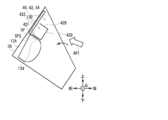
異物貯留部40に貯留された異物FSを取り除くとき、保守員は、まず、図5Aの接客部閉鎖状態から図5Bの接客部開放状態へ接客部36を回動させることにより、異物貯留部40にアクセス可能な状態とする。この接客部開放状態において保守員は、矢印AR1の方向から、図11に示すように支持部底面開口部44Daを介して貯留部42の異物貯留空間42Sを目視し、異物貯留部40の内部に異物FSが貯留されているか否かを確認する。
異物貯留部40に貯留された異物FSを取り除くとき、保守員は、まず、図5Aの接客部閉鎖状態から図5Bの接客部開放状態へ接客部36を回動させることにより、異物貯留部40にアクセス可能な状態とする。この接客部開放状態において保守員は、矢印AR1の方向から、図11に示すように支持部底面開口部44Daを介して貯留部42の異物貯留空間42Sを目視し、異物貯留部40の内部に異物FSが貯留されているか否かを確認する。
続いて保守員は、貯留部42における貯留部後側板開閉部42BLの貯留部後側板開閉部差込部42BLIを指で摘んで後方へ移動させることにより、貯留部後側板開閉部差込部42BLIを差込部保持部44DIから外す。さらに保守員は、引き続き貯留部後側板開閉部差込部42BLIを指で摘んで後方へ移動させることにより、開閉軸としての貯留部後側板開閉軸42BLaを軸として貯留部後側板開閉部42BLを回動させ図12に示す貯留部開放状態にすることにより、異物貯留空間42Sにおける貯留部後側板開閉部42BLの部分を外部に露出させ、保守員の指又はピンセットが異物貯留空間42Sに届く状態にする。この状態において保守員は、異物貯留空間42Sの異物FSを指又はピンセットで摘んで除去することにより、該異物FSを回収する。
[9.効果等]
以上の構成において硬貨処理装置10は、収容器13Aよりも、該収容器13Aに対しシャッタ開放状態においてシャッタ13Bが位置する側である後方に隣接するように異物貯留部40を設けるようにした。このため硬貨処理装置10は、硬貨集積空間13Cからシャッタ収容部間隙間SPやセンサ用孔部38に入り込んだ異物FSを異物貯留部40によって貯留することができる。これにより硬貨処理装置10は、異物FSが硬貨処理装置10内部の各部に入り込んでしまうことを防止することにより、違算の要因や駆動部に負荷を与えてしまうことを防止し、信頼性を向上させることができる。
以上の構成において硬貨処理装置10は、収容器13Aよりも、該収容器13Aに対しシャッタ開放状態においてシャッタ13Bが位置する側である後方に隣接するように異物貯留部40を設けるようにした。このため硬貨処理装置10は、硬貨集積空間13Cからシャッタ収容部間隙間SPやセンサ用孔部38に入り込んだ異物FSを異物貯留部40によって貯留することができる。これにより硬貨処理装置10は、異物FSが硬貨処理装置10内部の各部に入り込んでしまうことを防止することにより、違算の要因や駆動部に負荷を与えてしまうことを防止し、信頼性を向上させることができる。
また硬貨処理装置10は、貯留部42の壁部の一部分である貯留部後側板開閉部42BLの貯留部後側板開閉部差込部42BLIを、差込部保持部44DIに対し着脱可能とした。このため硬貨処理装置10は、貯留部42全体を支持部44から取り外すという煩雑な動作を保守員に強いることなく、貯留部後側板開閉部42BLの貯留部後側板開閉部差込部42BLIを差込部保持部44DIから外して貯留部開放状態にするだけで、貯留部後側板開閉部42BLが退避した空間を介し異物貯留空間42Sに貯留された異物FSを保守員に除去させることができる。これにより硬貨処理装置10は、異物FSを保守員に容易に回収させることができ、異物除去の作業性を向上させることができる。
さらに硬貨処理装置10は、異物貯留部40の貯留部42を透明部材で構成するようにした。このため異物貯留部40は、貯留部42の異物貯留空間42Sを貯留部42の外部から可視化でき、貯留部42に貯留された異物FSを貯留部42の外部から視認可能にできる。
さらに硬貨処理装置10は、支持部44において、貯留部42の貯留部底板右側部42DRと対向する支持部底板右側部44DRに、支持部底面開口部44Daを穿設するようにした。このため異物貯留部40は、図5Bに示す接客部開放状態において、矢印AR1の方向から、図11に示すように支持部底面開口部44Daを介し、貯留部42の異物貯留空間42Sを該貯留部42の外部から視認可能にできる。
以上の構成によれば硬貨処理装置10は、媒体としての硬貨が投入される投入部としての収容器13Aと、収容器13Aを開閉するシャッタ13Bとを有する入出金部13と、入出金部13に形成された隙間としての収容部内外連通空間48を挟んで収容器13Aの反対側に配置され、収容部内外連通空間48から入り込んだ異物FSを貯留する異物貯留部40とを設けるようにした。これにより硬貨処理装置10は、硬貨集積空間13Cから収容部内外連通空間48に入り込んだ異物FSを異物貯留部40によって貯留することができ、該異物FSが硬貨処理装置10内部の各部に入り込んでしまうことを防止できる。
[10.他の実施の形態]
[10-1.他の実施の形態1]
[10-1-1.異物貯留部の構成]
図5A、図5Bと対応する部材に同一符号を付した図14A、図14Bに示すように、他の実施の形態による異物貯留部140は、異物貯留部40と比較して、貯留部42に代わる貯留部142を有する点において相違するものの、他の点については同様に構成されている。
[10-1.他の実施の形態1]
[10-1-1.異物貯留部の構成]
図5A、図5Bと対応する部材に同一符号を付した図14A、図14Bに示すように、他の実施の形態による異物貯留部140は、異物貯留部40と比較して、貯留部42に代わる貯留部142を有する点において相違するものの、他の点については同様に構成されている。
貯留部142は、貯留部42と比較して、貯留部後側板42Bに代わる貯留部後側板142Bと、貯留部底板42Dに代わる貯留部底板142Dとを有する点において相違するものの、他の点については同様に構成されている。貯留部後側板142Bは、貯留部後側板開閉部42BLが設けられていないと共に、貯留部後側板142Bに対し、貯留部後側板142Bと貯留部底板142Dとの接続部である貯留部後側板底板接続部42Baxを軸として、貯留部底板142Dに対し、右側面視で時計回り及び反時計回りに回動可能となっている。
貯留部142は、貯留部後側板底板接続部42Baxが、接客部閉鎖状態と接客部開放状態との間を遷移する際に接客部36と共に可動しない、接客部36以外の箇所である硬貨処理装置筐体11と、リンク機構(図示せず)で繋がっている。この貯留部142は、接客部閉鎖状態(図14A)においては貯留部42(図5A)と同様の形状である。一方、貯留部142は、接客部閉鎖状態(図14A)から接客部開放状態(図14B)へ遷移する際、貯留部後側板142Bがリンク機構により後方へ引っ張られることにより、貯留部後側板142Bが、鉛直方向に対し上端部が後方へ向かうように傾斜する。この状態において貯留部後側板142Bは、後方へ退避し、異物貯留空間42Sの後側面を外部に大きく露出させる。
上述した貯留部42は、接客部36の回動に伴い、貯留部42全体が変形せずに接客部36と共に回動した。これに対し貯留部142は、接客部36の回動に伴い、貯留部前側板42F及び貯留部底板142Dは接客部36と共に回動するものの、貯留部後側板142Bは接客部36と共に回動せず、異物貯留空間42Sを外部に大きく露出させて開放させる。
このため異物貯留部140は、異物貯留部40と比較して、接客部36を回動させるだけで、貯留部後側板142Bが貯留部底板142Dに対し回動し、異物貯留空間42Sの後側面を露出させ、貯留部142に貯留された異物FSを貯留部142の外部から視認可能にできると共に、貯留部後側板開閉部42BLを開閉させるという動作を保守員に行わせることなく、異物FSを回収させることができる。
[10-1-2.異物除去方法]
異物貯留部140に貯留された異物FSを取り除くとき、保守員は、まず、図14Aの接客部閉鎖状態から図14Bの接客部開放状態へ接客部36を回動させることにより、異物貯留部140にアクセス可能な状態とする。このとき貯留部142は、貯留部後側板142Bがリンク機構により後方へ引っ張られることにより、異物貯留空間42Sの後側面を外部に大きく露出させる。この接客部開放状態において保守員は、矢印AR2の方向から、貯留部142の異物貯留空間42Sを目視し、異物貯留部140の内部に異物FSが貯留されているか否かを確認する。続いて保守員は、貯留部後側板142Bから異物貯留空間42Sの異物FSを指又はピンセットで摘んで除去することにより、該異物FSを回収する。
異物貯留部140に貯留された異物FSを取り除くとき、保守員は、まず、図14Aの接客部閉鎖状態から図14Bの接客部開放状態へ接客部36を回動させることにより、異物貯留部140にアクセス可能な状態とする。このとき貯留部142は、貯留部後側板142Bがリンク機構により後方へ引っ張られることにより、異物貯留空間42Sの後側面を外部に大きく露出させる。この接客部開放状態において保守員は、矢印AR2の方向から、貯留部142の異物貯留空間42Sを目視し、異物貯留部140の内部に異物FSが貯留されているか否かを確認する。続いて保守員は、貯留部後側板142Bから異物貯留空間42Sの異物FSを指又はピンセットで摘んで除去することにより、該異物FSを回収する。
[10-1-3.効果等]
以上の構成において貯留部142は、接客部36の開閉動作に貯留部後側板142Bの開閉を連動させ、接客部36が接客部閉鎖状態から接客部開放状態へ回動した際に、接客部36の回動につられて貯留部後側板142Bが異物貯留空間42Sから離れるように貯留部底板142Dに対し回動するようにした。
以上の構成において貯留部142は、接客部36の開閉動作に貯留部後側板142Bの開閉を連動させ、接客部36が接客部閉鎖状態から接客部開放状態へ回動した際に、接客部36の回動につられて貯留部後側板142Bが異物貯留空間42Sから離れるように貯留部底板142Dに対し回動するようにした。
このため貯留部142は、異物貯留部140にアクセスする際に必ず必要となる動作である、接客部36を接客部閉鎖状態から接客部開放状態へ回動させるという動作を保守員に行わせるだけで、異物貯留空間42Sの後側面を露出させ、貯留部142に貯留された異物FSを貯留部142の外部から視認可能にできると共に異物FSを回収させることができる。
これにより貯留部142は、硬貨処理装置10と比較して、外部からの異物貯留部140内部の異物FSの視認性をより一層向上できると共に、異物FSの回収の容易性をより一層向上できる。
その他の点においても、異物貯留部140は、異物貯留部40と同様の作用効果を奏し得る。
[10-2.他の実施の形態2]
なお上述した実施の形態においては、貯留部42をマイラー(登録商標)により構成する場合について述べた。本発明はこれに限らず、貯留部42を他の種々の素材により構成しても良い。
なお上述した実施の形態においては、貯留部42をマイラー(登録商標)により構成する場合について述べた。本発明はこれに限らず、貯留部42を他の種々の素材により構成しても良い。
[10-3.他の実施の形態3]
また上述した実施の形態においては、貯留部42全体を透明な樹脂フィルムであるマイラー(登録商標)により構成する場合について述べた。本発明はこれに限らず、貯留部42の少なくとも一部分は透明でなくても良い。その場合、支持部底面開口部44Daを介し異物貯留空間42Sを視認させるために、特に貯留部底板42Dは透明であると好ましい。
また上述した実施の形態においては、貯留部42全体を透明な樹脂フィルムであるマイラー(登録商標)により構成する場合について述べた。本発明はこれに限らず、貯留部42の少なくとも一部分は透明でなくても良い。その場合、支持部底面開口部44Daを介し異物貯留空間42Sを視認させるために、特に貯留部底板42Dは透明であると好ましい。
[10-4.他の実施の形態4]
さらに上述した実施の形態においては、貯留部42で異物FSを貯留し、該貯留部42を支持部44により支持する場合について述べた。本発明はこれに限らず、支持部44を例えば透明なプラスチック等の成形品で形成することにより、該支持部44の強度を保つことができれば、支持部44を省略しても良い。
さらに上述した実施の形態においては、貯留部42で異物FSを貯留し、該貯留部42を支持部44により支持する場合について述べた。本発明はこれに限らず、支持部44を例えば透明なプラスチック等の成形品で形成することにより、該支持部44の強度を保つことができれば、支持部44を省略しても良い。
[10-5.他の実施の形態5]
さらに上述した実施の形態においては、一組の貯留部後側板開閉部差込部42BLI及び差込部保持部44DIをそれぞれ貯留部42及び支持部44に形成する場合について述べた。本発明はこれに限らず、二組の貯留部後側板開閉部差込部42BLI及び差込部保持部44DIをそれぞれ貯留部42及び支持部44に形成し、貯留部42における、一方の組の貯留部後側板開閉部差込部42BLIと他方の組の貯留部後側板開閉部差込部42BLIとの間の壁部を、支持部44から着脱可能にしても良い。
さらに上述した実施の形態においては、一組の貯留部後側板開閉部差込部42BLI及び差込部保持部44DIをそれぞれ貯留部42及び支持部44に形成する場合について述べた。本発明はこれに限らず、二組の貯留部後側板開閉部差込部42BLI及び差込部保持部44DIをそれぞれ貯留部42及び支持部44に形成し、貯留部42における、一方の組の貯留部後側板開閉部差込部42BLIと他方の組の貯留部後側板開閉部差込部42BLIとの間の壁部を、支持部44から着脱可能にしても良い。
[10-6.他の実施の形態6]
さらに上述した実施の形態においては、貯留部後側板開閉部42BLを貯留部42における壁部の一部分である貯留部後側板42Bの一部分に形成する場合について述べた。本発明はこれに限らず、異物貯留空間42Sを外部に露出させる開閉部を、貯留部底板42Dに形成しても良い。
さらに上述した実施の形態においては、貯留部後側板開閉部42BLを貯留部42における壁部の一部分である貯留部後側板42Bの一部分に形成する場合について述べた。本発明はこれに限らず、異物貯留空間42Sを外部に露出させる開閉部を、貯留部底板42Dに形成しても良い。
[10-7.他の実施の形態7]
さらに上述した実施の形態においては、支持部底板右側部44DRに支持部底面開口部44Daを穿設する場合について述べた。本発明はこれに限らず、例えば支持部底板右側部44DRの一部を折り曲げる等、他の種々の方法で開口部を形成しても良い。
さらに上述した実施の形態においては、支持部底板右側部44DRに支持部底面開口部44Daを穿設する場合について述べた。本発明はこれに限らず、例えば支持部底板右側部44DRの一部を折り曲げる等、他の種々の方法で開口部を形成しても良い。
[10-8.他の実施の形態8]
さらに上述した実施の形態においては、支持部底面開口部44Daを平面視で左右方向に長い長方形状とする場合について述べた。本発明はこれに限らず、支持部底面開口部44Daは、平面視で三角形状、正方形状、円形状や楕円形状等、種々の形状でも良い。
さらに上述した実施の形態においては、支持部底面開口部44Daを平面視で左右方向に長い長方形状とする場合について述べた。本発明はこれに限らず、支持部底面開口部44Daは、平面視で三角形状、正方形状、円形状や楕円形状等、種々の形状でも良い。
[10-9.他の実施の形態9]
さらに上述した実施の形態においては、接客部36は回動することにより接客部閉鎖状態と接客部開放状態とを遷移する場合について述べた。本発明はこれに限らず、接客部36はスライド移動する等、種々の方式で移動することにより、接客部閉鎖状態と接客部開放状態とを遷移しても良い。
さらに上述した実施の形態においては、接客部36は回動することにより接客部閉鎖状態と接客部開放状態とを遷移する場合について述べた。本発明はこれに限らず、接客部36はスライド移動する等、種々の方式で移動することにより、接客部閉鎖状態と接客部開放状態とを遷移しても良い。
[10-10.他の実施の形態10]
さらに上述した実施の形態においては、収容器13Aとシャッタ13Bとの隙間であるシャッタ収容部間隙間SPと、収容器13A自身に形成されたセンサ用孔部38とに入り込んだ異物FSを貯留する異物貯留部40に本発明を適用する場合について述べた。本発明はこれに限らず、センサ用孔部や搬送路を有する、例えば硬貨の種類毎に硬貨を集積させるスタッカ等、必要不可欠な隙間が存在する他の種々の箇所に、本発明を適用しても良い。
さらに上述した実施の形態においては、収容器13Aとシャッタ13Bとの隙間であるシャッタ収容部間隙間SPと、収容器13A自身に形成されたセンサ用孔部38とに入り込んだ異物FSを貯留する異物貯留部40に本発明を適用する場合について述べた。本発明はこれに限らず、センサ用孔部や搬送路を有する、例えば硬貨の種類毎に硬貨を集積させるスタッカ等、必要不可欠な隙間が存在する他の種々の箇所に、本発明を適用しても良い。
[10-11.他の実施の形態11]
さらに上述した実施の形態においては、使用者との間で種々の取引を行う現金自動預払機1(図1)の硬貨処理装置10に組み込まれる異物貯留部40に本発明を適用する場合について述べた。本発明はこれに限らず、例えば金融機関やスーパーマーケットの店舗内等に設置され、該店舗の職員や係員等の操作に従って硬貨の計数や分類等の処理を行う現金管理装置等、硬貨を取り扱う種々の装置に本発明を適用しても良い。
さらに上述した実施の形態においては、使用者との間で種々の取引を行う現金自動預払機1(図1)の硬貨処理装置10に組み込まれる異物貯留部40に本発明を適用する場合について述べた。本発明はこれに限らず、例えば金融機関やスーパーマーケットの店舗内等に設置され、該店舗の職員や係員等の操作に従って硬貨の計数や分類等の処理を行う現金管理装置等、硬貨を取り扱う種々の装置に本発明を適用しても良い。
[10-12.他の実施の形態12]
さらに本発明は、上述した各実施の形態及び他の実施の形態に限定されるものではない。すなわち本発明は、上述した各実施の形態と上述した他の実施の形態の一部又は全部を任意に組み合わせた実施の形態や、一部を抽出した実施の形態にもその適用範囲が及ぶものである。
さらに本発明は、上述した各実施の形態及び他の実施の形態に限定されるものではない。すなわち本発明は、上述した各実施の形態と上述した他の実施の形態の一部又は全部を任意に組み合わせた実施の形態や、一部を抽出した実施の形態にもその適用範囲が及ぶものである。
[10-13.他の実施の形態13]
さらに上述した実施の形態においては、入出金部としての入出金部13と、異物貯留部としての異物貯留部40とによって、媒体処理装置としての硬貨処理装置10を構成する場合について述べた。本発明はこれに限らず、その他種々の構成でなる入出金部と、異物貯留部とによって、硬貨処理装置を構成しても良い。
さらに上述した実施の形態においては、入出金部としての入出金部13と、異物貯留部としての異物貯留部40とによって、媒体処理装置としての硬貨処理装置10を構成する場合について述べた。本発明はこれに限らず、その他種々の構成でなる入出金部と、異物貯留部とによって、硬貨処理装置を構成しても良い。
本発明は、例えば使用者との間で硬貨に関する取引処理を行う現金自動預払機等で利用できる。
1……現金自動預払機、2……筐体、3……応対部、4……通帳入出口、5……カード入出口、6……硬貨入出金口、7……紙幣入出金口、8……操作表示部、9……主制御部、10……硬貨処理装置、11……硬貨処理装置筐体、12……硬貨制御部、13……入出金部、13A……収容器、13B……シャッタ、13Bb……シャッタ板状部、13Bp……シャッタ突起部、13C……硬貨集積空間、13D……硬貨集積板、13d……後側板、13di……傾斜部、13ds……シャッタ対向部、14……シュート部、15……上分離部、15A……集積分離部、15B……分離搬送部、16……認識搬送部、17……受渡部、18……ピンベルト搬送部、19……分岐部、20……スタッカ分岐部、21……スタッカ部、22……出金搬送部、23……一時保留部、24……補充回収庫、25……第1補充リジェクト庫、26……第2補充リジェクト庫、27……リジェクト庫、28……取忘取込庫、29……下分離部、29A……集積分離部、29B……分離搬送部、30、31……案内部、32……集積部、33……繰出部、34……シャッタ対向部溝部、36……接客部、36a……接客部回動軸、38……センサ用孔部、40、140……異物貯留部、42、142……貯留部、42S……異物貯留空間、42D、142D……貯留部底板、42DR……貯留部底板右側部、42DL……貯留部底板左側部、42B、142B……貯留部後側板、42BR……貯留部後側板右側部、42BL……貯留部後側板開閉部、42BLI……貯留部後側板開閉部差込部、42BLa……貯留部後側板開閉軸、42LR……貯留部内側左側板、42LL……貯留部外側左側板、42F……貯留部前側板、42FD……貯留部前側板下側部、42FI……貯留部前側板傾斜部、42FIe……貯留部前側板傾斜部前端部、42Bax……貯留部後側板底板接続部、44……支持部、44D……支持部底板、44DR……支持部底板右側部、44Da……支持部底面開口部、44DI……差込部保持部、44DL……支持部底板左側部、44R……支持部右側板、44L……支持部左側板、44F……支持部前側板、46……両面テープ、48……収容部内外連通空間、SP…シャッタ収容部間隙間、SP2……貯留部収容器間隙間、FS……異物、AR1、AR2……矢印。
Claims (14)
- 媒体が投入される投入部と、前記投入部を開閉するシャッタとを有する入出金部と、
前記入出金部に形成された隙間を挟んで前記投入部の反対側に配置され、前記隙間から入り込んだ異物を貯留する異物貯留部と
を有する媒体処理装置。 - 前記異物貯留部は、
前記異物を貯留する空間を形成する底板部と壁部とを有し、
前記底板部又は前記壁部の少なくとも一部分に前記空間を開閉する開閉部が形成される
請求項1に記載の媒体処理装置。 - 前記開閉部は、開閉軸を中心に開閉可能に設けられる
請求項2に記載の媒体処理装置。 - 前記開閉部は、一端側に前記開閉軸が設けられ、他端側に固定部が設けられ、前記固定部が前記底板部に設けられた保持部に対し着脱可能に固定される
請求項3に記載の媒体処理装置。 - 前記異物貯留部は、
前記異物を貯留する空間を形成する貯留部と、
前記貯留部を下側から支持する支持部と
により構成される
請求項1に記載の媒体処理装置。 - 前記異物貯留部は、少なくとも一部分が透明部材で構成される
請求項1に記載の媒体処理装置。 - 前記貯留部は、少なくとも一部分が透明部材で構成される
請求項5に記載の媒体処理装置。 - 前記支持部は、
前記貯留部が位置する上面から、下面までに亘って、開口部が形成される
請求項5に記載の媒体処理装置。 - 前記支持部は、
前記貯留部に形成され前記空間を開閉する開閉部が係止されることで前記開閉部を閉鎖状態とし、前記開閉部の係止が外されることで前記開閉部を開放状態とする保持部が形成される
請求項5に記載の媒体処理装置。 - 前記隙間は、前記シャッタと前記投入部との間における空間である
請求項1に記載の媒体処理装置。 - 前記隙間は、前記投入部の外部と内部とを連通させるよう配された、センサの光を通過させる孔部である
請求項1に記載の媒体処理装置。 - 前記異物貯留部は、
前記異物を貯留する空間を形成する底板部と壁部とを有し、
前記壁部における前記投入部側の端部は、前記隙間における前記異物貯留部側の端部よりも前記投入部側に位置する
請求項1に記載の媒体処理装置。 - 前記異物貯留部と前記入出金部とを含み、軸を中心に回動する接客部をさらに有し、
前記異物貯留部は、前記異物を貯留する空間を形成する底板部と壁部とを備え、
前記接客部の回動動作と、前記壁部が前記底板部に対し軸を中心に回動することにより前記空間を開閉する動作とを連動させるリンク機構をさらに有し、
前記リンク機構は、前記接客部が開かれる方向への回動に連動して、前記空間を開放させるよう前記壁部を移動させる
請求項1に記載の媒体処理装置。 - 使用者の操作を受け付ける操作部と、
請求項1に記載の媒体処理装置と
を具えることを特徴とする現金取扱装置。
Priority Applications (1)
| Application Number | Priority Date | Filing Date | Title |
|---|---|---|---|
| US17/922,920 US12236737B2 (en) | 2020-06-05 | 2021-04-21 | Medium processing device and cash handling device |
Applications Claiming Priority (2)
| Application Number | Priority Date | Filing Date | Title |
|---|---|---|---|
| JP2020-098894 | 2020-06-05 | ||
| JP2020098894A JP7424215B2 (ja) | 2020-06-05 | 2020-06-05 | 媒体処理装置及び現金取扱装置 |
Publications (1)
| Publication Number | Publication Date |
|---|---|
| WO2021246071A1 true WO2021246071A1 (ja) | 2021-12-09 |
Family
ID=78830348
Family Applications (1)
| Application Number | Title | Priority Date | Filing Date |
|---|---|---|---|
| PCT/JP2021/016149 Ceased WO2021246071A1 (ja) | 2020-06-05 | 2021-04-21 | 媒体処理装置及び現金取扱装置 |
Country Status (3)
| Country | Link |
|---|---|
| US (1) | US12236737B2 (ja) |
| JP (1) | JP7424215B2 (ja) |
| WO (1) | WO2021246071A1 (ja) |
Families Citing this family (2)
| Publication number | Priority date | Publication date | Assignee | Title |
|---|---|---|---|---|
| JP2024072507A (ja) * | 2022-11-16 | 2024-05-28 | ニデックインスツルメンツ株式会社 | カードリーダ |
| US20260188083A1 (en) * | 2024-12-31 | 2026-07-02 | Cardtronics Usa, Inc. | Pocket lower cover for an automated teller machine |
Citations (3)
| Publication number | Priority date | Publication date | Assignee | Title |
|---|---|---|---|---|
| JPH1069562A (ja) * | 1997-06-20 | 1998-03-10 | Toshiba Corp | 自動取引装置 |
| JPH10222721A (ja) * | 1997-01-31 | 1998-08-21 | Oki Electric Ind Co Ltd | 紙幣入出金装置 |
| JP2012088998A (ja) * | 2010-10-21 | 2012-05-10 | Oki Electric Ind Co Ltd | シャッタ開閉機構および自動取引装置 |
Family Cites Families (4)
| Publication number | Priority date | Publication date | Assignee | Title |
|---|---|---|---|---|
| JP3673052B2 (ja) | 1997-03-11 | 2005-07-20 | グローリー工業株式会社 | 硬貨入出金機の取引口装置 |
| JP6466072B2 (ja) * | 2014-03-06 | 2019-02-06 | グローリー株式会社 | 紙葉類投入装置および紙葉類処理機 |
| JP2018150133A (ja) * | 2017-03-13 | 2018-09-27 | グローリー株式会社 | 紙葉類処理装置および紙葉類処理機 |
| JP6941870B2 (ja) * | 2018-01-26 | 2021-09-29 | ローレル精機株式会社 | 紙葉類処理装置 |
-
2020
- 2020-06-05 JP JP2020098894A patent/JP7424215B2/ja active Active
-
2021
- 2021-04-21 US US17/922,920 patent/US12236737B2/en active Active
- 2021-04-21 WO PCT/JP2021/016149 patent/WO2021246071A1/ja not_active Ceased
Patent Citations (3)
| Publication number | Priority date | Publication date | Assignee | Title |
|---|---|---|---|---|
| JPH10222721A (ja) * | 1997-01-31 | 1998-08-21 | Oki Electric Ind Co Ltd | 紙幣入出金装置 |
| JPH1069562A (ja) * | 1997-06-20 | 1998-03-10 | Toshiba Corp | 自動取引装置 |
| JP2012088998A (ja) * | 2010-10-21 | 2012-05-10 | Oki Electric Ind Co Ltd | シャッタ開閉機構および自動取引装置 |
Also Published As
| Publication number | Publication date |
|---|---|
| JP7424215B2 (ja) | 2024-01-30 |
| JP2021192203A (ja) | 2021-12-16 |
| US20230169815A1 (en) | 2023-06-01 |
| US12236737B2 (en) | 2025-02-25 |
Similar Documents
| Publication | Publication Date | Title |
|---|---|---|
| WO2016038963A1 (ja) | 媒体処理装置及び媒体取引装置 | |
| JP7192424B2 (ja) | 硬貨処理装置及び自動取引装置 | |
| WO2016013324A1 (ja) | 媒体処理装置及び媒体取引装置 | |
| JP3192973B2 (ja) | 紙幣入出金装置 | |
| JP7424215B2 (ja) | 媒体処理装置及び現金取扱装置 | |
| JP4830414B2 (ja) | 紙幣入出金機 | |
| JP6413688B2 (ja) | 自動取引装置 | |
| JP6464658B2 (ja) | 紙幣取引装置 | |
| JP2009151354A (ja) | 紙幣入出金機 | |
| JP2021056554A (ja) | 現金処理装置 | |
| JP7327112B2 (ja) | 媒体処理装置及び自動取引装置 | |
| JP6098455B2 (ja) | 紙幣処理装置 | |
| JP4839896B2 (ja) | 紙幣入出金機およびその紙幣入出金機を搭載した自動取引装置 | |
| JP5277757B2 (ja) | 紙幣処理装置 | |
| CN107408321B (zh) | 纸币处理装置以及纸币的精查处理方法 | |
| JP4750308B2 (ja) | 自動取引装置 | |
| JP2718808B2 (ja) | 自動取引装置 | |
| WO2025074708A1 (ja) | 紙幣処理装置 | |
| JP2024056467A (ja) | 硬貨処理装置及び自動取引装置 | |
| JPH0620216Y2 (ja) | 紙幣取扱装置 | |
| JP2025126769A (ja) | 紙幣処理装置 | |
| JP2018032265A (ja) | 媒体処理装置及び媒体取引装置 | |
| JP6888394B2 (ja) | 媒体収納庫及び媒体取引装置 | |
| KR20070031764A (ko) | 금융자동화기기의 출금 방법 및 장치 | |
| KR20130075483A (ko) | 지폐처리장치 및 지폐처리방법 |
Legal Events
| Date | Code | Title | Description |
|---|---|---|---|
| 121 | Ep: the epo has been informed by wipo that ep was designated in this application |
Ref document number: 21818488 Country of ref document: EP Kind code of ref document: A1 |
|
| NENP | Non-entry into the national phase |
Ref country code: DE |
|
| 122 | Ep: pct application non-entry in european phase |
Ref document number: 21818488 Country of ref document: EP Kind code of ref document: A1 |
|
| WWG | Wipo information: grant in national office |
Ref document number: 17922920 Country of ref document: US |