WO2021241615A1 - ガスケット - Google Patents
ガスケット Download PDFInfo
- Publication number
- WO2021241615A1 WO2021241615A1 PCT/JP2021/019926 JP2021019926W WO2021241615A1 WO 2021241615 A1 WO2021241615 A1 WO 2021241615A1 JP 2021019926 W JP2021019926 W JP 2021019926W WO 2021241615 A1 WO2021241615 A1 WO 2021241615A1
- Authority
- WO
- WIPO (PCT)
- Prior art keywords
- outer peripheral
- gasket
- peripheral portion
- inner peripheral
- bead
- Prior art date
- Legal status (The legal status is an assumption and is not a legal conclusion. Google has not performed a legal analysis and makes no representation as to the accuracy of the status listed.)
- Ceased
Links
Images


Classifications
-
- F—MECHANICAL ENGINEERING; LIGHTING; HEATING; WEAPONS; BLASTING
- F16—ENGINEERING ELEMENTS AND UNITS; GENERAL MEASURES FOR PRODUCING AND MAINTAINING EFFECTIVE FUNCTIONING OF MACHINES OR INSTALLATIONS; THERMAL INSULATION IN GENERAL
- F16J—PISTONS; CYLINDERS; SEALINGS
- F16J15/00—Sealings
- F16J15/02—Sealings between relatively-stationary surfaces
- F16J15/06—Sealings between relatively-stationary surfaces with solid packing compressed between sealing surfaces
- F16J15/08—Sealings between relatively-stationary surfaces with solid packing compressed between sealing surfaces with exclusively metal packing
- F16J15/0818—Flat gaskets
- F16J15/0825—Flat gaskets laminated
-
- F—MECHANICAL ENGINEERING; LIGHTING; HEATING; WEAPONS; BLASTING
- F16—ENGINEERING ELEMENTS AND UNITS; GENERAL MEASURES FOR PRODUCING AND MAINTAINING EFFECTIVE FUNCTIONING OF MACHINES OR INSTALLATIONS; THERMAL INSULATION IN GENERAL
- F16J—PISTONS; CYLINDERS; SEALINGS
- F16J15/00—Sealings
- F16J15/02—Sealings between relatively-stationary surfaces
- F16J15/06—Sealings between relatively-stationary surfaces with solid packing compressed between sealing surfaces
- F16J15/10—Sealings between relatively-stationary surfaces with solid packing compressed between sealing surfaces with non-metallic packing
- F16J15/12—Sealings between relatively-stationary surfaces with solid packing compressed between sealing surfaces with non-metallic packing with metal reinforcement or covering
- F16J15/121—Sealings between relatively-stationary surfaces with solid packing compressed between sealing surfaces with non-metallic packing with metal reinforcement or covering with metal reinforcement
- F16J15/122—Sealings between relatively-stationary surfaces with solid packing compressed between sealing surfaces with non-metallic packing with metal reinforcement or covering with metal reinforcement generally parallel to the surfaces
-
- F—MECHANICAL ENGINEERING; LIGHTING; HEATING; WEAPONS; BLASTING
- F16—ENGINEERING ELEMENTS AND UNITS; GENERAL MEASURES FOR PRODUCING AND MAINTAINING EFFECTIVE FUNCTIONING OF MACHINES OR INSTALLATIONS; THERMAL INSULATION IN GENERAL
- F16J—PISTONS; CYLINDERS; SEALINGS
- F16J15/00—Sealings
- F16J15/02—Sealings between relatively-stationary surfaces
- F16J15/06—Sealings between relatively-stationary surfaces with solid packing compressed between sealing surfaces
- F16J15/08—Sealings between relatively-stationary surfaces with solid packing compressed between sealing surfaces with exclusively metal packing
- F16J15/0818—Flat gaskets
- F16J2015/085—Flat gaskets without fold over
-
- F—MECHANICAL ENGINEERING; LIGHTING; HEATING; WEAPONS; BLASTING
- F16—ENGINEERING ELEMENTS AND UNITS; GENERAL MEASURES FOR PRODUCING AND MAINTAINING EFFECTIVE FUNCTIONING OF MACHINES OR INSTALLATIONS; THERMAL INSULATION IN GENERAL
- F16J—PISTONS; CYLINDERS; SEALINGS
- F16J15/00—Sealings
- F16J15/02—Sealings between relatively-stationary surfaces
- F16J15/06—Sealings between relatively-stationary surfaces with solid packing compressed between sealing surfaces
- F16J15/08—Sealings between relatively-stationary surfaces with solid packing compressed between sealing surfaces with exclusively metal packing
- F16J15/0818—Flat gaskets
- F16J2015/0856—Flat gaskets with a non-metallic coating or strip
Definitions
- the present invention relates to a gasket, and more particularly to a gasket used in a vehicle, a general-purpose machine, or the like.
- gaskets are used to seal the housing in engines, devices that house electronic components inside, and the like.
- the gasket is elasto-plastically deformed by being sandwiched between a pair of members that are combined to form a housing in a compressed state, and the pair of members are sealed to seal the housing.
- Automobiles may travel in beach areas or areas where snow-melting agents are sprayed. At this time, salt water or snow-melting agent adheres to automobile parts, and salt water or snow-melting agent enters the gaps between the members that hold the gasket. It may stay. The retained salt water or snow melting agent may cause corrosion on the member that holds the gasket.
- the member holding the gasket When the member holding the gasket is formed of an aluminum alloy, the member holding the gasket has a high ionization tendency, so that the member holding the gasket is easily corroded by the retained salt water or the snow melting agent. If this corroded portion exceeds the gasket's sealing line, the gasket's sealing function will be reduced or extinguished. For this reason, parts using gaskets are subjected to a salt spray test in advance to evaluate their corrosion resistance. In the salt spray test, in the parts to which the gasket is attached, salt water is retained in the gaps between the members that hold the gasket, and these parts are alternately repeated in a dry state and a wet state to evaluate the corrosion resistance performance against salt water. Is done.
- the member for pinching the gasket is not corroded by the corrosive foreign matter, and the member for pinching the gasket.
- a gasket structure for suppressing corrosion due to corrosive foreign matter has been proposed.
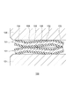
- Patent Document 1 discloses a gasket structure 100 in which two metal gaskets 101 face each other and are pressed between a pair of members 120 and 121, as shown in FIG.
- the metal gasket 101 is formed by an inner peripheral portion 103 and an outer peripheral portion 104 extending in parallel with each other and a bead portion 105 extending diagonally between the inner peripheral portion 103 and the outer peripheral portion 104 in a free state without being pinched. It has a metal substrate 102 and a rubber layer 106 that covers the upper surface and the lower surface of the metal substrate 102.
- the outer peripheral portion 104 of the upper metal gasket 101 contacts the upper member 120 via the rubber layer 106, and the outer peripheral portion 104 of the lower metal gasket 101 is on the lower side.
- the member 121 is brought into contact with the member 121 via the rubber layer 106 to reduce the space in which corrosive foreign matter such as salt water stays between the pair of members 120 and 121, and the members 120 and 121 are corroded by the corrosive foreign matter. We are trying to suppress it.
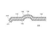
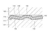
- Patent Document 2 discloses a gasket 110 including a metal substrate 111 and a rubber layer 116 covering the upper and lower surfaces of the metal substrate 111, as shown in FIG.
- the metal substrate 111 has an inner peripheral portion 112 and an outer peripheral portion 113 extending parallel to each other in a free state, and a full bead-shaped bead portion 114 extending upward between the inner peripheral portion 112 and the outer peripheral portion 113. It has a bent portion 115 formed by bending the outer peripheral side end portion of the outer peripheral portion 113 downward.
- the mounted state as shown in FIG.
- the gasket 110 is sandwiched between the pair of members 120 and 121, and the outer peripheral side end of the outer peripheral portion 113 and the bead portion 114 form a rubber layer 116 on the upper member 120.
- the inner peripheral side end of the outer peripheral portion 113, the outer peripheral side end of the inner peripheral portion 112, and the outer peripheral side end of the bent portion 115 come into contact with the lower member 121 via the rubber layer 116.
- the gasket 110 reduces the space in which corrosive foreign substances such as salt water stay between the pair of members 120 and 121, and suppresses the corrosion of the members 120 and 121.
- the above-mentioned conventional gasket structure 100 and gasket 110 can suppress corrosion of the members 120 and 121 that sandwich them.
- the reaction force of the pair of metal gaskets 101 pressed is large, and the reaction force is large for fastening the members 120 and 121. Fastening force was required.
- the gasket 110 is compressed and pressed by the full bead-shaped bead portion 114 and the bent portion 115 in the mounted state, the reaction force of the sandwiched gasket 110 is large, and the members 120 and 121 are fastened. Needed a large fastening force.
- some conventional gaskets can reduce the corrosion of the members to be attached, they require a large fastening force to fasten the members.
- the conventional gasket is required to have a structure capable of reducing the reaction force in the mounted state and suppressing the deterioration of the sealing performance due to corrosive foreign substances such as salt water and snow melting agents. Further, the conventional gasket has been required to have a structure capable of further reducing the gap between the members holding the gasket in which corrosive foreign matter can stay.
- the present invention has been made in view of the above-mentioned problems, and an object thereof is to prevent deterioration of sealing performance due to corrosive foreign substances such as salt water and snow melting agents while reducing reaction force in the mounted state. Is to provide a gasket that can be used.
- the gasket according to the present invention is a gasket including a metal substrate made of metal and a coating layer formed by an elastic body covering at least a part of the metal substrate, and is the metal substrate.
- a metal substrate made of metal and a coating layer formed by an elastic body covering at least a part of the metal substrate, and is the metal substrate.
- the outer peripheral portion extends along a plane.
- the outer peripheral portion extends along a curved surface that protrudes toward the facing side of the other surface and has a curvature smaller than the curvature of the bead portion.
- the inner peripheral portion extends diagonally to the side facing the other of the pair of surfaces with respect to the direction in which the bead portion protrudes.
- At least a part of the inner peripheral portion is formed symmetrically with respect to at least a part of the outer peripheral portion with respect to the bead portion.
- the gasket according to the present invention it is possible to suppress the deterioration of the sealing performance due to corrosive foreign substances such as salt water and snow melting agents while reducing the reaction force in the mounted state.
- FIG. 3 is a partially enlarged cross-sectional view showing an enlarged inner peripheral portion of the gasket shown in FIG. 2. It is sectional drawing which shows the state of the gasket shown in FIG. 1 in the mounting process. It is sectional drawing which shows the state of the gasket shown in FIG. 1 in the mounted state. It is sectional drawing along the line AA which shows the modification of the gasket which concerns on 1st Embodiment of this invention.
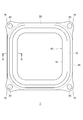
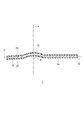
- FIG. 1 is a plan view for showing a schematic structure of the gasket 1 according to the first embodiment of the present invention
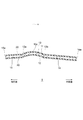
- FIG. 2 is a cross-sectional view showing a cross section of the gasket 1 shown in FIG.
- a cross section (hereinafter, also simply referred to as a cross section) along a line AA orthogonal to the extending direction of the above is shown.
- the gasket 1 is used in a vehicle, a general-purpose industrial machine, or the like, and is pinched between two members to undergo elasto-plastic deformation and is used to seal between the two members.
- the gasket 1 is sandwiched between two members forming a housing for accommodating electronic parts and the like in, for example, in the engine room of an automobile to seal the housing and to prevent corrosiveness such as salt water and snow melting agent. Protect electronic parts from foreign substances.
- FIGS. 1 and 2 the gasket 1 in a free state, which is not sandwiched between members, is shown.
- the gasket 1 is a gasket including a metal substrate 10 made of metal and a coating layer 20 formed of an elastic body covering at least a part of the metal substrate 10.
- the metal substrate 10 has a pair of faces 11 and 12 facing each other, and a bead portion 13 and a bead portion 13 which are portions where one of the pair of faces (face 11) projects toward the facing side. It has an inner peripheral portion 14 extending from the inner peripheral side edge of the bead portion 13 and an outer peripheral portion 15 extending from the outer peripheral side edge of the bead portion 13.
- the outer peripheral portion 15 extends obliquely to the side facing the other (surface 12) of the pair of surfaces with respect to the direction in which the bead portion 13 protrudes.
- the gasket 1 will be specifically described.
- the inner peripheral side is the closed space side (inner side) surrounded by the annular gasket 1
- the outer peripheral side is the annular gasket 1 as shown in FIG. It is the space side that is not closed, and is the outer side opposite to the inner side.
- the upper side is referred to as the upper side and the lower side is referred to as the lower side in FIG.
- the upper side and the lower side are used for convenience of explanation, and do not specify the mounting posture of the gasket 1.
- the gasket 1 is a flat plate-shaped member extending in an annular shape, and more specifically, the gasket 1 is formed so as to extend in a rectangular annular shape in a plan view.
- the shape of the gasket 1 in a plan view is not limited to a rectangle, and may be another shape.
- the gasket 1 is formed with a bolt hole 30 which is a through hole through which a bolt for fastening two members to be attached and allowing the gasket 1 to be sandwiched between the members is inserted. ..
- the metal substrate 10 is a plate-shaped member having a uniform or substantially uniform thickness and formed of an elastic metal material.
- the metal substrate 10 forms the gasket 1, and in the present embodiment, the metal substrate 10 is formed so as to extend in a rectangular annular shape in a plan view.
- the metal substrate 10 may be formed of a single elastic metal plate, or may be formed by laminating and stacking a plurality of elastic metal plates.
- As the metal material of the metal substrate 10 stainless steel, cold-rolled steel, zinc-plated steel, aluminum alloy, or the like is used.
- the bead portion 13, the inner peripheral portion 14, and the outer peripheral portion 15 are formed by processing a metal plate by press working or forging, and are integrally formed of the same metal material.
- the metal substrate 10 has the above-mentioned pair of surfaces, the upper surface 11 and the lower surface 12. As shown in FIG. 2, the upper surface 11 and the lower surface 12 face each other in the thickness direction of the metal substrate 10, the upper surface 11 faces the upper side, and the lower surface 12 faces the lower side. Further, in the cross section, the contours drawn by the upper surface 11 and the lower surface 12 are symmetric or substantially symmetrical with respect to the center line connecting the centers in the thickness direction of the metal substrate 10.
- the bead portion 13 is a portion of the metal substrate 10 projecting upward facing the upper surface 11, and forms a bead in the gasket 1. Specifically, as shown in FIG. 2, the bead portion 13 projects upward in the protruding direction line x, which is a line extending in the protruding direction of the bead portion 13, and the upper surface 11 has an upwardly convex curved surface. The lower surface 12 forms a concave concave surface on the upper side.
- the bead portion 13 extends in cross section, for example, along an arc of uniform curvature. The bead portion 13 does not have to extend along an arc of uniform curvature in the cross section.
- the bead portion 13 has a symmetrical or substantially symmetrical shape with respect to the projecting direction line x in the cross section.
- the bead portion 13 does not have to have a shape symmetrical with respect to the protrusion direction line x.
- the protrusion direction line x can be a line (normal line) orthogonal to the top portion 13c of the bead portion 13.
- the top portion 13c of the bead portion 13 is a portion located at the uppermost side of the bead portion 13 in the projecting direction of the bead portion 13, or a portion in the vicinity of this portion.
- the outer peripheral portion 15 extends a predetermined width from the outer peripheral side edge (outer peripheral edge 13a) of the bead portion 13 toward the outer peripheral side. As described above, the outer peripheral portion 15 extends diagonally downward with respect to the direction in which the bead portion 13 protrudes (protruding direction line x). That is, the outer peripheral portion 15 is a tapered portion. Specifically, as shown in FIG. 2, the outer peripheral portion 15 extends along a plane, and for example, in the cross section, the outer peripheral portion 15 extends linearly from the outer peripheral edge 13a of the bead portion 13. Further, in the cross section, the outer peripheral portion 15 extends diagonally downward with respect to the protrusion direction line x.
- the extension direction line l1 which is a line connecting the center of the outer peripheral portion 15 in the thickness direction in the cross section is a straight line, and is below the extension direction line l1 and the protrusion direction line x.
- the side angle ⁇ is smaller than 90 °.
- the outer peripheral portion 15 does not have to extend linearly as described above.
- the extension direction line l1 extending in the extension direction of the outer peripheral portion 15 may be a substantially straight line instead of a straight line.
- the outer peripheral portion 15 extends diagonally downward with respect to the direction in which the bead portion 13 protrudes (protruding direction line x). That is, as shown in FIG. 3, in the cross section, the lower sandwich angle ⁇ between the extension direction line l1 and the protrusion direction line x of the outer peripheral portion 15 is smaller than 90 °.
- the inner peripheral portion 14 forms a tapered portion, and as shown in FIGS. 1 and 2, the inner peripheral portion 14 faces the inner peripheral side from the inner peripheral side edge (inner peripheral edge 13b) of the bead portion 13.
- the bead portion 13 extends diagonally downward with respect to the projecting direction (protruding direction line x).
- the inner peripheral portion 14 extends along a plane, and for example, in the cross section, the inner peripheral portion 14 extends linearly from the inner peripheral edge 13b of the bead portion 13. .. Further, in the cross section, the inner peripheral portion 14 extends diagonally downward with respect to the projecting direction line x. More specifically, as shown in FIG.
- the extension direction line l2 which is a line connecting the center of the inner peripheral portion 14 in the thickness direction in the cross section, is a straight line, and the extension direction line l2 and the protrusion direction line x
- the lower sandwich angle ⁇ is smaller than 90 °.
- the inner peripheral portion 14 does not have to extend linearly as described above.
- the extension direction line l2 extending in the extension direction of the inner peripheral portion 14 may be a substantially straight line instead of a straight line.
- the outer peripheral portion 15 extends diagonally downward with respect to the direction in which the bead portion 13 protrudes (protruding direction line x). That is, as shown in FIG. 4, in the cross section, the lower sandwich angle ⁇ between the extension direction line l2 and the protrusion direction line x of the inner peripheral portion 14 is smaller than 90 °.
- At least a part of the inner peripheral portion 14 is formed symmetrically with respect to at least a part of the outer peripheral portion 15 with respect to the bead portion 13.
- the length of the inner peripheral portion 14 in the extending direction is longer than the length of the outer peripheral portion 15 in the extending direction (extending direction line l1 direction), which is shown in FIG.
- a part of the inner peripheral portion 14 on the bead portion 13 side is symmetrical with respect to the entire outer peripheral portion 15 with respect to the protruding direction line x.
- the outer peripheral portion 15 and the inner peripheral portion 14 are inclined with respect to the protrusion direction line x in the same manner as each other, and the sandwich angle ⁇ between the extension direction line l1 and the protrusion direction line x of the outer peripheral portion 15 is set.
- the angle is the same as the sandwiching angle ⁇ between the extension direction line l2 of the inner peripheral portion 14 and the protrusion direction line x.
- the length of the inner peripheral portion 14 in the extending direction and the length of the outer peripheral portion 15 in the extending direction may be the same.
- the entire inner peripheral portion 14 and the entire outer peripheral portion 15 are symmetrical with respect to the protrusion direction line x.
- the length of the outer peripheral portion 15 in the extending direction is longer than the length of the inner peripheral portion 14 in the extending direction, and in the cross section, a part of the outer peripheral portion 15 on the bead portion 13 side is related to the protrusion direction line x. , It may be symmetrical with the whole of the inner peripheral portion 14.
- the outer peripheral portion 15 and the inner peripheral portion 14 do not have to be inclined with respect to the protruding direction line x in the same manner as each other, and the sandwiching angle between the extending direction line l1 of the outer peripheral portion 15 and the protruding direction line x.
- ⁇ does not have to be at the same angle as the narrowing angle ⁇ between the extension direction line l2 of the inner peripheral portion 14 and the protrusion direction line x.
- the sandwich angle ⁇ between the extension direction line l1 of the outer peripheral portion 15 and the protrusion direction line x is larger than the sandwich angle ⁇ between the extension direction line l2 of the inner peripheral portion 14 and the protrusion direction line x. It may be small.
- the coating layer 20 is an elastic body that covers at least a part of the metal substrate 10.
- the covering layer 20 covers the entire upper surface 11 and the entire lower surface 12 of the metal substrate 10. That is, the covering layer 20 integrally covers the bead portion 13, the inner peripheral portion 14, and the outer peripheral portion 15 from the upper side and the lower side, respectively.
- the covering layer 20 does not cover the inner peripheral edge (inner peripheral edge 14a) of the inner peripheral portion 14 and the outer peripheral edge (outer peripheral edge 15a) of the outer peripheral portion 15.
- the covering layer 20 may cover a part or all of the inner peripheral edge 14a of the inner peripheral portion 14, and the covering layer 20 may cover a part or the whole of the outer peripheral edge 15a of the outer peripheral portion 15. You may be.
- the elastic body forming the coating layer 20 there is an elastic body made of synthetic rubber.
- the synthetic rubber include nitrile rubber (NBR), styrene butadiene rubber (SBR), fluororubber (FKM), acrylic rubber (ACM), and synthetic rubber containing at least one of silicon rubber.
- NBR nitrile rubber
- SBR styrene butadiene rubber
- FKM fluororubber
- ACM acrylic rubber
- synthetic rubber containing at least one of silicon rubber synthetic rubber containing at least one of silicon rubber.
- the coating layer 20 has a uniform or substantially uniform thickness in a cross section, is formed in the form of a film or a sheet, and is attached to the metal substrate 10.
- the elastic body of the covering layer 20 may be a foam rubber.
- the coating layer 20 is attached to the metal substrate 10 by, for example, an adhesive.
- a base treatment layer formed by surface treatment of the surface of the metal substrate 10 may be formed between the metal substrate 10 and the adhesive layer.
- this base treatment for example, there is zinc phosphate treatment.
- the width of the periphery of the portion where the bolt hole 30 is formed in the gasket 1 is wider than that of the other portions.
- the bolt hole 30 is formed in the bolt hole piece 16 which is a portion of the metal substrate 10 extending from the outer peripheral edge 15a of the outer peripheral portion 15 to the outer peripheral side. As shown in FIG. 1, the bolt hole piece 16 is widened to a size in which the bolt hole 30 can be formed.
- the gasket 1 is formed so that the shape of the cross section orthogonal to the extending direction of the gasket 1 is uniform or substantially uniform in the extending direction of the gasket 1 except for the portion where the bolt hole piece 16 is formed. There is.
- the gasket 1 may have a portion where the bolt hole piece 16 is not formed, and the shape of the cross section orthogonal to the extending direction of the gasket 1 is not uniform in the extending direction of the gasket 1.
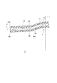
- FIG. 5 is a cross-sectional view showing the state of the gasket 1 in the process of mounting on the mounting target
- FIG. 6 is a cross-sectional view showing the state of the gasket 1 in the mounted state mounted on the mounting target.
- the gasket 1 In the mounted state, the gasket 1 is sandwiched between the two members 70 and 71 to be mounted, is sandwiched between the members 70 and 71, undergoes elasto-plastic deformation, and seals between the members 70 and 71. ing.
- the member 70 and the member 71 are fastened with the flat surface 70a formed on the member 70 and the flat surface 71a formed on the member 71 facing each other, and the gasket 1 is formed between the flat surface 70a and the flat surface 71a. Is pinched and elasto-plastically deformed.
- the members 70 and 71 are, for example, members forming a cylinder block and a cylinder head of an engine, a cylinder block and an oil pan, a case of a fuel cell stack, and a housing of other devices, and the flat surfaces 70a and 71a are, for example, examples. It is formed on the flange portion formed on the members 70 and 71.
- the gasket 1 is elasto-plastically deformed from the free state shown in FIG. 2, and a desired contact pressure is generated at the contact portion (seal line) with the members 70 and 71. The conclusion is made until it is done. Fastening is done, for example, by screwing bolts together.
- the members 70 and 71 are fastened, and the bead portion 13 contacts (surface contact) the flat surface 70a of the upper member 70 via the covering layer 20 and presses downward (in the direction of arrow z1 in FIG. 5). Will be done. Further, the outer peripheral edge 15a on the lower surface 12 of the outer peripheral portion 15 and its vicinity (hereinafter referred to as the outer peripheral end portion 15b) come into contact with the flat surface 71a of the lower member 71 via the covering layer 20 and are upward (arrow in FIG. 5). It is pressed in the z2 direction).
- the inner peripheral edge 14a on the lower surface 12 of the inner peripheral portion 14 and its vicinity come into contact with the flat surface 71a of the member 71 via the covering layer 20 and are upward (arrow z2 in FIG. 5).
- (Direction) is pressed.
- the metal substrate 10 is elasto-plastically deformed, the bead portion 13 extends to the outer peripheral side and the inner peripheral side, and the bead portion 13 of the inner peripheral portion 14 and the outer peripheral portion 15 is (1).
- the inclination (with respect to the projecting direction line x) increases, that is, the sandwiching angles ⁇ and ⁇ increase, and the height of the metal substrate 10 decreases.
- the height of the metal substrate 10 is the height of the metal substrate 10 in the protrusion direction line x direction.
- the gasket 1 In the fastening process, when the fastening force of the members 70 and 71, that is, the axial force of the bolt reaches a predetermined set value, the gasket 1 is in a state of generating a desired reaction force, and the fastening of the members 70 and 71 is completed and the gasket 1 is It will be in the mounted state.
- the upper covering layer 20 in the top 13c of the bead portion 13 and its vicinity is in contact with the flat surface 70a, and the outer peripheral edge 13a of the bead portion 13 and the lower covering in the vicinity thereof are in contact with each other.
- the layer 20 and the lower covering layer 20 in the vicinity of the inner peripheral edge 13b of the bead portion 13 are in contact with the plane 71a (fully compressed state).
- the bead portion 13 forms three seal lines s1, s2, and s3.
- the seal line s1 is a seal line formed by contact between the upper covering layer 20 and the flat surface 70a in and near the top portion 13c of the bead portion 13.
- the seal line s2 is a seal line formed by contact between the outer peripheral edge 13a of the bead portion 13 and the lower covering layer 20 and the plane 71a in the vicinity thereof.
- the seal line s3 is a seal line formed by contact between the inner peripheral edge 13b of the bead portion 13 and the lower covering layer 20 and the plane 71a in the vicinity thereof.
- the gasket 1 seals between the flat surface 70a and the flat surface 71a in the mounted state, and the object inside the members 70, 71, such as lubricating oil, etc., is sealed from the inner peripheral side through the gap between the flat surfaces 70a and 71a. Is prevented from leaking out, and rainwater, dust, etc. are prevented from entering from the outer peripheral side through the gap between the flat surfaces 70a and 71a.
- the upper covering layer 20 in the outer peripheral end portion 15b of the outer peripheral portion 15 is in contact with the flat surface 70a without forming a gap.
- the lower covering layer 20 at the outer peripheral end portion 15b of the outer peripheral portion 15 is in contact with the flat surface 71a with no gap or almost no gap. This is because, in the free state of the gasket 1, the outer peripheral portion 15 connected to the bead portion 13 is inclined downward with respect to the protruding direction line x of the bead portion 13 to form a tapered portion. ..
- the outer peripheral portion 15 is inclined upward with respect to the protrusion direction line x so that the lower covering layer 20 in the outer peripheral end portion 15b, particularly the outer peripheral edge 15a, rises from the flat surface 71a.
- the outer peripheral portion 15 in the free state, is inclined downward with respect to the projecting direction line x, so that the bead portion 13 is compressed in the fastening process of the members 70 and 71 and the height is reduced. Even so, as shown in FIG. 5, the outer peripheral portion 15 can maintain a state of being inclined downward. Therefore, in the process of fastening the members 70 and 71, the lower covering layer 20 at the outer peripheral end portion 15b of the outer peripheral portion 15 can continue to maintain contact with the flat surface 71a. Further, even in the mounted state in the fully compressed state, the outer peripheral portion 15 is maintained in a state of being inclined downward, or the outer peripheral portion 15 is in a state orthogonal to the protrusion direction line x, or the outer peripheral end portion 15b in particular.
- the outer peripheral portion 15 is inclined upward with respect to the protrusion direction line x so that the lower covering layer 20 on the outer peripheral edge 15a does not rise from the plane 71a, and the lower peripheral portion 15 on the outer peripheral end portion 15b is in a state of being inclined upward.
- the coating layer 20 continues to maintain contact with the plane 71a.
- the gasket 1 on which the lower covering layer 20 on the outer peripheral end portion 15b, particularly the outer peripheral edge 15a, rises from the flat surface 71a is prevented from jumping up, and the outer peripheral end portion (outer peripheral end portion 15b) and the flat surface 70a of the gasket 1 are prevented from jumping up. No gap is formed between the 71a and the 71a.
- the gasket 1 can prevent a space from being formed on the outer peripheral side between the members 70 and 71, and corrosive foreign matter such as salt water or a snow melting agent enters the outer peripheral side of the seal lines s1 and s2. You can get rid of it.
- the outer peripheral portion 15 is inclined downward in the mounted state in the fully compressed state.
- the state may not be maintained, or the outer peripheral portion 15 may not be in a state orthogonal to the protrusion direction line x, and the outer peripheral portion 15 may be in a state of being inclined upward.
- the outer peripheral portion 15 forms a tapered portion inclined downward in the free state, the jumping of the outer peripheral portion 15 in the compression process is suppressed as in the above case, and the outer peripheral portion 15 is in a fully compressed state.
- the outer peripheral portion 15 can be maintained in a state in which the outer peripheral portion 15 is not significantly tilted upward with respect to the protrusion direction line x. Therefore, even if a gap is formed between the outer peripheral end of the gasket 1 and the flat surface 71a, this gap becomes a very small gap, and corrosive foreign matter does not enter the gap, or Even if corrosive foreign matter enters this gap, the amount of foreign matter that stays can be reduced to a very small amount. On the other hand, also in this case, no gap is formed between the outer peripheral end portion (outer peripheral end portion 15b) of the gasket 1 and the upper flat surface 70a in the mounted state in the fully compressed state.
- the gasket 1 can reduce the space that communicates with the outside formed between the member 70 and the member 71 on the outer peripheral side by the outer peripheral portion 15, or can provide such a space that communicates with the outside. Can be eliminated. Therefore, according to the gasket 1, it is possible to prevent corrosive foreign matter from corroding the flat surfaces 70a and 70b of the members 70 and 71 to be mounted on the outer peripheral side of the seal lines s1 and s2 by the outer peripheral portion 15. , It is possible to prevent the seal lines s1 to s3 from being cut off due to corrosion. This makes it possible to prevent deterioration of the sealing performance due to corrosive foreign substances such as salt water and snow melting agents. In particular, when the members 70 and 71 are made of an aluminum alloy such as ADC12 which is easily corroded by salt water or the like, the gasket 1 is suitable.
- the height of the gasket 1 is the height of the bead portion 13 and the height based on the inclination of the outer peripheral portion 15. It has become. Therefore, the height of the bead portion 13 of the gasket 1 is lower than the height of the bead of the gasket having the same height as the conventional one. Therefore, the reaction force generated by the bead portion 13 in the fully compressed state can be reduced, and the fastening force for bringing the members 70 and 71 to be mounted into the fully compressed state can be reduced.
- the inner peripheral portion 14 is also inclined downward with respect to the protrusion direction line x like the outer peripheral portion 15, the inner peripheral portion 14 is similarly in the above-mentioned outer peripheral portion 15 in the mounting process and the mounting state, respectively. It acts and has the same effect as that of the outer peripheral portion 15.
- the planes 70a and 71a can be sealed on the inner peripheral side of the seal lines s1 and s3, and the sealing performance can be improved even for the sealed object on the inner peripheral side.
- the internal seal line s3 can prevent the foreign matter from further entering, and the salt water of the member 71 can be prevented. It is possible to suppress the spread of corrosion due to such factors. Similarly, even if a liquid or the like leaks to the outside beyond the seal line s3 formed by the inner peripheral portion 14, it is possible to prevent further leakage of the liquid leaked by the seal line s2.
- the reaction force of the gasket 1 in the mounted state is reduced, and the deterioration of the sealing performance due to corrosive foreign substances such as salt water and snow melting agent is suppressed. be able to.
- the posture of the outer peripheral portion 15 in the mounted state changes depending on the length of the outer peripheral portion 15 in the extending direction in the free state, the inclination angle (sandwich angle ⁇ ) of the outer peripheral portion 15, the shape of the bead portion 13, and the like.
- the outer peripheral portion 15 is maintained in an inclined state downward, or the outer peripheral portion 15 is in a state orthogonal to the protrusion direction line x, or the outer peripheral end portion 15b.
- the outer peripheral portion 15 in the free state is in a state in which the outer peripheral portion 15 is inclined upward with respect to the protrusion direction line x so that the lower covering layer 20 on the outer peripheral edge 15a does not rise from the plane 71a. It is preferable to set the length in the extending direction, the inclination angle of the outer peripheral portion 15, the shape of the bead portion 13, and the like. The same applies to the inner peripheral portion 14.
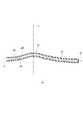
- FIG. 7 is a cross-sectional view taken along the line AA showing a modification of the gasket 1.
- the outer peripheral portion 15 does not extend along a plane, but may extend along a curved surface that bends so as to project downward.
- the outer peripheral portion 15 may extend along a curved surface that protrudes downward and has a curvature smaller than the curvature of the bead portion 13 in the cross section. That is, as shown in FIG. 7, the extension direction line l1 of the outer peripheral portion 15 may draw a downwardly convex curve.
- the degree of bending of the outer peripheral portion 15 is set so that, for example, the curvature of the extension direction line l1 does not cause the gasket 1 to jump up as described above.
- the inner peripheral portion 14 may also extend along a curved surface that bends so as to project downward, as in the outer peripheral portion 15 in this modification. In this case as well, the gasket 1 exhibits the above-mentioned effects.
- the outer peripheral portion 15 does not extend along a plane, and may extend along a curved surface that bends so as to protrude upward, contrary to the protruding direction of the outer peripheral portion 15 shown in FIG. 7.
- the outer peripheral portion 15 may extend along a curved surface that protrudes upward and has a curvature smaller than the curvature of the bead portion 13 in the cross section.
- the degree of bending of the outer peripheral portion 15 is set, for example, the curvature of the extension direction line l1 so that the gasket 1 does not jump up as described above.
- the inner peripheral portion 14 may also extend along a curved surface that bends so as to project upward.
- the gasket 1 exhibits the above-mentioned effects.
- either one of the inner peripheral portion 14 and the outer peripheral portion 15 may extend along a curved surface that bends so as to project upward, and the other may extend along a curved surface that bends so as to protrude downward.
- the inner peripheral portion 14 of the gasket 1 does not form a tapered portion in the free state, and extends along a plane orthogonal to or substantially orthogonal to the protrusion direction line x. May be good. That is, in the gasket 1 in the free state, the narrowing angle ⁇ between the extension direction line l2 of the inner peripheral portion 14 and the protrusion direction line x may be 90 ° or approximately 90 °. Also in this case, the outer peripheral portion 15 of the gasket 1 exerts the above-mentioned effects. Further, either one of the inner peripheral portion 14 and the outer peripheral portion 15 may extend in a planar shape as described above (see FIG. 2), and the other may extend in a curved surface shape as described above (see FIG. 7). ..
- the present invention is not limited to the above-described embodiments of the present invention, and includes all aspects included in the concept and claims of the present invention.
- each configuration may be selectively combined as appropriate so as to exhibit at least a part of the above-mentioned effects.
- the shape, material, arrangement, size, manufacturing method, etc. of each component in the above embodiment can be appropriately changed depending on the specific usage mode of the present invention.
- the coating layer 20 is not provided on the entire upper surface 11 and the lower surface 12 of the metal substrate 10, and the upper surface 11 or the lower surface 12 is provided with the coating layer 20 only on a part thereof.
- the covering layer 20 may be provided only on a part of each of the upper surface 11 and the lower surface 12.
- the covering layer 20 is provided on the upper surface 11 and the lower surface 12 at the outer peripheral end portion 15b of the outer peripheral portion 15 and the portion forming the seal lines s1 to s3.
Landscapes
- Engineering & Computer Science (AREA)
- General Engineering & Computer Science (AREA)
- Mechanical Engineering (AREA)
- Gasket Seals (AREA)
Priority Applications (4)
| Application Number | Priority Date | Filing Date | Title |
|---|---|---|---|
| CN202180032982.0A CN115516232B (zh) | 2020-05-28 | 2021-05-26 | 密封垫 |
| EP21812008.7A EP4160055A4 (en) | 2020-05-28 | 2021-05-26 | SEAL |
| JP2022526602A JP7421642B2 (ja) | 2020-05-28 | 2021-05-26 | ガスケット |
| US17/923,268 US12326192B2 (en) | 2020-05-28 | 2021-05-26 | Gasket |
Applications Claiming Priority (2)
| Application Number | Priority Date | Filing Date | Title |
|---|---|---|---|
| JP2020093376 | 2020-05-28 | ||
| JP2020-093376 | 2020-05-28 |
Publications (1)
| Publication Number | Publication Date |
|---|---|
| WO2021241615A1 true WO2021241615A1 (ja) | 2021-12-02 |
Family
ID=78744554
Family Applications (1)
| Application Number | Title | Priority Date | Filing Date |
|---|---|---|---|
| PCT/JP2021/019926 Ceased WO2021241615A1 (ja) | 2020-05-28 | 2021-05-26 | ガスケット |
Country Status (5)
| Country | Link |
|---|---|
| US (1) | US12326192B2 (https=) |
| EP (1) | EP4160055A4 (https=) |
| JP (1) | JP7421642B2 (https=) |
| CN (1) | CN115516232B (https=) |
| WO (1) | WO2021241615A1 (https=) |
Citations (6)
| Publication number | Priority date | Publication date | Assignee | Title |
|---|---|---|---|---|
| JP2002195099A (ja) * | 2000-12-27 | 2002-07-10 | Ket & Ket:Kk | 金属ガスケット |
| JP2013036607A (ja) | 2011-07-11 | 2013-02-21 | Nok Corp | 金属ガスケットによるシール構造 |
| JP2013061002A (ja) | 2011-09-13 | 2013-04-04 | Nok Corp | 金属ガスケットによるシール構造 |
| JP2015169290A (ja) * | 2014-03-07 | 2015-09-28 | 日本リークレス工業株式会社 | 金属ガスケット |
| JP2016156448A (ja) * | 2015-02-24 | 2016-09-01 | Nok株式会社 | 金属ガスケット |
| JP6178036B1 (ja) * | 2015-11-27 | 2017-08-09 | Nok株式会社 | 金属ガスケット |
Family Cites Families (15)
| Publication number | Priority date | Publication date | Assignee | Title |
|---|---|---|---|---|
| JPH07253162A (ja) * | 1994-06-30 | 1995-10-03 | Nippon Riikuresu Kogyo Kk | メタルガスケット |
| JP3129626B2 (ja) * | 1995-02-06 | 2001-01-31 | 日本ガスケット株式会社 | 金属製ガスケット |
| JPH11230355A (ja) * | 1998-02-19 | 1999-08-27 | Ishikawa Gasket Co Ltd | ガスケット |
| DE10029352B4 (de) * | 2000-06-15 | 2007-01-04 | Reinz-Dichtungs-Gmbh & Co. Kg | Flachdichtung |
| KR100549913B1 (ko) | 2002-04-04 | 2006-02-06 | 니혼 메타루 가스켓토 가부시키가이샤 | 금속개스킷 |
| JP3769549B2 (ja) * | 2003-03-26 | 2006-04-26 | 石川ガスケット株式会社 | メタルガスケット |
| JP2006144808A (ja) * | 2004-11-16 | 2006-06-08 | Ishikawa Gasket Co Ltd | メタルガスケット |
| JP5344222B2 (ja) * | 2008-12-26 | 2013-11-20 | 日本ガスケット株式会社 | シリンダヘッドガスケットにおけるオイル落し穴のシール構造 |
| JP5699039B2 (ja) * | 2011-05-26 | 2015-04-08 | 日本リークレス工業株式会社 | 金属ガスケット |
| DE102013205220A1 (de) * | 2013-03-25 | 2014-09-25 | Elringklinger Ag | Steuerplatte |
| DE202013009887U1 (de) * | 2013-11-29 | 2014-12-01 | Reinz-Dichtungs-Gmbh | Metallische Flachdichtung |
| WO2015109171A1 (en) * | 2014-01-17 | 2015-07-23 | Federal-Mogul Corporation | Gasket component with half-stop and method of manufacturing |
| DE202015103421U1 (de) * | 2015-06-29 | 2016-06-30 | Reinz-Dichtungs-Gmbh | Getriebesteuervorrichtung |
| JP6367177B2 (ja) * | 2015-12-28 | 2018-08-01 | ニチアス株式会社 | シリンダヘッドガスケット及びシリンダヘッドガスケット用ステンレス鋼板 |
| JP6438632B1 (ja) * | 2017-03-06 | 2018-12-19 | Nok株式会社 | ガスケット |
-
2021
- 2021-05-26 CN CN202180032982.0A patent/CN115516232B/zh active Active
- 2021-05-26 WO PCT/JP2021/019926 patent/WO2021241615A1/ja not_active Ceased
- 2021-05-26 US US17/923,268 patent/US12326192B2/en active Active
- 2021-05-26 EP EP21812008.7A patent/EP4160055A4/en active Pending
- 2021-05-26 JP JP2022526602A patent/JP7421642B2/ja active Active
Patent Citations (6)
| Publication number | Priority date | Publication date | Assignee | Title |
|---|---|---|---|---|
| JP2002195099A (ja) * | 2000-12-27 | 2002-07-10 | Ket & Ket:Kk | 金属ガスケット |
| JP2013036607A (ja) | 2011-07-11 | 2013-02-21 | Nok Corp | 金属ガスケットによるシール構造 |
| JP2013061002A (ja) | 2011-09-13 | 2013-04-04 | Nok Corp | 金属ガスケットによるシール構造 |
| JP2015169290A (ja) * | 2014-03-07 | 2015-09-28 | 日本リークレス工業株式会社 | 金属ガスケット |
| JP2016156448A (ja) * | 2015-02-24 | 2016-09-01 | Nok株式会社 | 金属ガスケット |
| JP6178036B1 (ja) * | 2015-11-27 | 2017-08-09 | Nok株式会社 | 金属ガスケット |
Non-Patent Citations (1)
| Title |
|---|
| See also references of EP4160055A4 |
Also Published As
| Publication number | Publication date |
|---|---|
| US12326192B2 (en) | 2025-06-10 |
| EP4160055A4 (en) | 2024-06-26 |
| US20230235820A1 (en) | 2023-07-27 |
| JPWO2021241615A1 (https=) | 2021-12-02 |
| JP7421642B2 (ja) | 2024-01-24 |
| EP4160055A1 (en) | 2023-04-05 |
| CN115516232A (zh) | 2022-12-23 |
| CN115516232B (zh) | 2025-08-05 |
Similar Documents
| Publication | Publication Date | Title |
|---|---|---|
| JP4156527B2 (ja) | 金属ガスケット | |
| CN103635724B (zh) | 利用金属衬垫的密封构造 | |
| CN107250629B (zh) | 金属垫片 | |
| US5294134A (en) | Metallic gasket | |
| JPH08100859A (ja) | 金属製ガスケット | |
| US20070200301A1 (en) | Sealing Gasket With Flexible Stopper | |
| JPH10259873A (ja) | 金属製ガスケット | |
| WO2021241615A1 (ja) | ガスケット | |
| US11499635B2 (en) | Gasket and sealing structure | |
| EP1510734B1 (en) | Sealing gasket with flexible stopper | |
| JPWO2017187978A1 (ja) | ガスケット | |
| JPH055331Y2 (https=) | ||
| US11248703B2 (en) | Metal gasket | |
| JPH0529416Y2 (https=) | ||
| JPS6114606Y2 (https=) | ||
| JP3467062B2 (ja) | メタルガスケット | |
| JPH073085Y2 (ja) | 積層金属ガスケット | |
| JPH0420996Y2 (https=) | ||
| JP2001065696A (ja) | シリンダヘッドガスケット | |
| JP4326293B2 (ja) | 密封構造 | |
| JPH0613427Y2 (ja) | 金属ガスケット | |
| KR100199520B1 (ko) | 한쌍의 판만으로 구성된 금속 적층형 가스킷 | |
| JP2007198472A (ja) | 金属ガスケット | |
| JPH0714265U (ja) | ガスケット | |
| JP2006038034A (ja) | 金属ガスケット |
Legal Events
| Date | Code | Title | Description |
|---|---|---|---|
| 121 | Ep: the epo has been informed by wipo that ep was designated in this application |
Ref document number: 21812008 Country of ref document: EP Kind code of ref document: A1 |
|
| ENP | Entry into the national phase |
Ref document number: 2022526602 Country of ref document: JP Kind code of ref document: A |
|
| NENP | Non-entry into the national phase |
Ref country code: DE |
|
| ENP | Entry into the national phase |
Ref document number: 2021812008 Country of ref document: EP Effective date: 20230102 |
|
| WWG | Wipo information: grant in national office |
Ref document number: 17923268 Country of ref document: US |
|
| WWG | Wipo information: grant in national office |
Ref document number: 202180032982.0 Country of ref document: CN |