WO2021241350A1 - 路面評価装置および路面評価方法 - Google Patents
路面評価装置および路面評価方法 Download PDFInfo
- Publication number
- WO2021241350A1 WO2021241350A1 PCT/JP2021/018956 JP2021018956W WO2021241350A1 WO 2021241350 A1 WO2021241350 A1 WO 2021241350A1 JP 2021018956 W JP2021018956 W JP 2021018956W WO 2021241350 A1 WO2021241350 A1 WO 2021241350A1
- Authority
- WO
- WIPO (PCT)
- Prior art keywords
- vehicle
- information
- road surface
- roughness value
- unit
- Prior art date
Links
- 238000000034 method Methods 0.000 title description 11
- 230000003746 surface roughness Effects 0.000 claims abstract description 91
- 230000033001 locomotion Effects 0.000 claims abstract description 21
- 238000012937 correction Methods 0.000 claims description 91
- 238000011156 evaluation Methods 0.000 claims description 50
- 239000000725 suspension Substances 0.000 claims description 40
- 238000009795 derivation Methods 0.000 claims description 25
- 238000012423 maintenance Methods 0.000 claims description 4
- 230000001133 acceleration Effects 0.000 description 58
- 238000004891 communication Methods 0.000 description 22
- 238000010586 diagram Methods 0.000 description 12
- 238000004364 calculation method Methods 0.000 description 7
- 238000004519 manufacturing process Methods 0.000 description 6
- 238000010521 absorption reaction Methods 0.000 description 5
- 230000005540 biological transmission Effects 0.000 description 4
- 238000005259 measurement Methods 0.000 description 3
- 230000002093 peripheral effect Effects 0.000 description 2
- 238000012545 processing Methods 0.000 description 2
- 230000000694 effects Effects 0.000 description 1
- 238000000605 extraction Methods 0.000 description 1
- 230000005484 gravity Effects 0.000 description 1
- 230000001771 impaired effect Effects 0.000 description 1
- 239000000203 mixture Substances 0.000 description 1
- 238000012986 modification Methods 0.000 description 1
- 230000004048 modification Effects 0.000 description 1
Images


Classifications
-
- B—PERFORMING OPERATIONS; TRANSPORTING
- B60—VEHICLES IN GENERAL
- B60W—CONJOINT CONTROL OF VEHICLE SUB-UNITS OF DIFFERENT TYPE OR DIFFERENT FUNCTION; CONTROL SYSTEMS SPECIALLY ADAPTED FOR HYBRID VEHICLES; ROAD VEHICLE DRIVE CONTROL SYSTEMS FOR PURPOSES NOT RELATED TO THE CONTROL OF A PARTICULAR SUB-UNIT
- B60W40/00—Estimation or calculation of non-directly measurable driving parameters for road vehicle drive control systems not related to the control of a particular sub unit, e.g. by using mathematical models
- B60W40/02—Estimation or calculation of non-directly measurable driving parameters for road vehicle drive control systems not related to the control of a particular sub unit, e.g. by using mathematical models related to ambient conditions
- B60W40/06—Road conditions
-
- B—PERFORMING OPERATIONS; TRANSPORTING
- B60—VEHICLES IN GENERAL
- B60W—CONJOINT CONTROL OF VEHICLE SUB-UNITS OF DIFFERENT TYPE OR DIFFERENT FUNCTION; CONTROL SYSTEMS SPECIALLY ADAPTED FOR HYBRID VEHICLES; ROAD VEHICLE DRIVE CONTROL SYSTEMS FOR PURPOSES NOT RELATED TO THE CONTROL OF A PARTICULAR SUB-UNIT
- B60W50/00—Details of control systems for road vehicle drive control not related to the control of a particular sub-unit, e.g. process diagnostic or vehicle driver interfaces
- B60W50/08—Interaction between the driver and the control system
- B60W50/14—Means for informing the driver, warning the driver or prompting a driver intervention
-
- E—FIXED CONSTRUCTIONS
- E01—CONSTRUCTION OF ROADS, RAILWAYS, OR BRIDGES
- E01C—CONSTRUCTION OF, OR SURFACES FOR, ROADS, SPORTS GROUNDS, OR THE LIKE; MACHINES OR AUXILIARY TOOLS FOR CONSTRUCTION OR REPAIR
- E01C23/00—Auxiliary devices or arrangements for constructing, repairing, reconditioning, or taking-up road or like surfaces
- E01C23/01—Devices or auxiliary means for setting-out or checking the configuration of new surfacing, e.g. templates, screed or reference line supports; Applications of apparatus for measuring, indicating, or recording the surface configuration of existing surfacing, e.g. profilographs
-
- G—PHYSICS
- G01—MEASURING; TESTING
- G01B—MEASURING LENGTH, THICKNESS OR SIMILAR LINEAR DIMENSIONS; MEASURING ANGLES; MEASURING AREAS; MEASURING IRREGULARITIES OF SURFACES OR CONTOURS
- G01B21/00—Measuring arrangements or details thereof, where the measuring technique is not covered by the other groups of this subclass, unspecified or not relevant
- G01B21/30—Measuring arrangements or details thereof, where the measuring technique is not covered by the other groups of this subclass, unspecified or not relevant for measuring roughness or irregularity of surfaces
-
- G—PHYSICS
- G08—SIGNALLING
- G08G—TRAFFIC CONTROL SYSTEMS
- G08G1/00—Traffic control systems for road vehicles
-
- B—PERFORMING OPERATIONS; TRANSPORTING
- B60—VEHICLES IN GENERAL
- B60W—CONJOINT CONTROL OF VEHICLE SUB-UNITS OF DIFFERENT TYPE OR DIFFERENT FUNCTION; CONTROL SYSTEMS SPECIALLY ADAPTED FOR HYBRID VEHICLES; ROAD VEHICLE DRIVE CONTROL SYSTEMS FOR PURPOSES NOT RELATED TO THE CONTROL OF A PARTICULAR SUB-UNIT
- B60W2420/00—Indexing codes relating to the type of sensors based on the principle of their operation
- B60W2420/90—Single sensor for two or more measurements
- B60W2420/905—Single sensor for two or more measurements the sensor being an xyz axis sensor
-
- B—PERFORMING OPERATIONS; TRANSPORTING
- B60—VEHICLES IN GENERAL
- B60W—CONJOINT CONTROL OF VEHICLE SUB-UNITS OF DIFFERENT TYPE OR DIFFERENT FUNCTION; CONTROL SYSTEMS SPECIALLY ADAPTED FOR HYBRID VEHICLES; ROAD VEHICLE DRIVE CONTROL SYSTEMS FOR PURPOSES NOT RELATED TO THE CONTROL OF A PARTICULAR SUB-UNIT
- B60W2510/00—Input parameters relating to a particular sub-units
- B60W2510/22—Suspension systems
-
- B—PERFORMING OPERATIONS; TRANSPORTING
- B60—VEHICLES IN GENERAL
- B60W—CONJOINT CONTROL OF VEHICLE SUB-UNITS OF DIFFERENT TYPE OR DIFFERENT FUNCTION; CONTROL SYSTEMS SPECIALLY ADAPTED FOR HYBRID VEHICLES; ROAD VEHICLE DRIVE CONTROL SYSTEMS FOR PURPOSES NOT RELATED TO THE CONTROL OF A PARTICULAR SUB-UNIT
- B60W2520/00—Input parameters relating to overall vehicle dynamics
- B60W2520/10—Longitudinal speed
- B60W2520/105—Longitudinal acceleration
-
- B—PERFORMING OPERATIONS; TRANSPORTING
- B60—VEHICLES IN GENERAL
- B60W—CONJOINT CONTROL OF VEHICLE SUB-UNITS OF DIFFERENT TYPE OR DIFFERENT FUNCTION; CONTROL SYSTEMS SPECIALLY ADAPTED FOR HYBRID VEHICLES; ROAD VEHICLE DRIVE CONTROL SYSTEMS FOR PURPOSES NOT RELATED TO THE CONTROL OF A PARTICULAR SUB-UNIT
- B60W2520/00—Input parameters relating to overall vehicle dynamics
- B60W2520/12—Lateral speed
- B60W2520/125—Lateral acceleration
-
- B—PERFORMING OPERATIONS; TRANSPORTING
- B60—VEHICLES IN GENERAL
- B60W—CONJOINT CONTROL OF VEHICLE SUB-UNITS OF DIFFERENT TYPE OR DIFFERENT FUNCTION; CONTROL SYSTEMS SPECIALLY ADAPTED FOR HYBRID VEHICLES; ROAD VEHICLE DRIVE CONTROL SYSTEMS FOR PURPOSES NOT RELATED TO THE CONTROL OF A PARTICULAR SUB-UNIT
- B60W2530/00—Input parameters relating to vehicle conditions or values, not covered by groups B60W2510/00 or B60W2520/00
- B60W2530/20—Tyre data
-
- B—PERFORMING OPERATIONS; TRANSPORTING
- B60—VEHICLES IN GENERAL
- B60W—CONJOINT CONTROL OF VEHICLE SUB-UNITS OF DIFFERENT TYPE OR DIFFERENT FUNCTION; CONTROL SYSTEMS SPECIALLY ADAPTED FOR HYBRID VEHICLES; ROAD VEHICLE DRIVE CONTROL SYSTEMS FOR PURPOSES NOT RELATED TO THE CONTROL OF A PARTICULAR SUB-UNIT
- B60W2552/00—Input parameters relating to infrastructure
- B60W2552/35—Road bumpiness, e.g. potholes
-
- B—PERFORMING OPERATIONS; TRANSPORTING
- B60—VEHICLES IN GENERAL
- B60W—CONJOINT CONTROL OF VEHICLE SUB-UNITS OF DIFFERENT TYPE OR DIFFERENT FUNCTION; CONTROL SYSTEMS SPECIALLY ADAPTED FOR HYBRID VEHICLES; ROAD VEHICLE DRIVE CONTROL SYSTEMS FOR PURPOSES NOT RELATED TO THE CONTROL OF A PARTICULAR SUB-UNIT
- B60W2556/00—Input parameters relating to data
- B60W2556/45—External transmission of data to or from the vehicle
- B60W2556/50—External transmission of data to or from the vehicle of positioning data, e.g. GPS [Global Positioning System] data
Definitions
- the present invention relates to a road surface evaluation device and a road surface evaluation method for evaluating a road surface profile representing an uneven shape of a road surface.
- a road surface profile representing the uneven shape of the road surface of the road on which the vehicle travels is detected based on the lateral (lateral direction with respect to the traveling direction) acceleration measured by an acceleration sensor provided in the vehicle.
- a device is known (see, for example, Patent Document 1).
- the road surface evaluation device has a driving information acquisition unit that acquires driving information including information indicating the movement of a moving vehicle and vehicle position information, and a map including information on the road on which the vehicle travels. Based on the map information acquisition unit that acquires information, the vehicle information acquisition unit that acquires vehicle information including vehicle-specific information, and the travel information acquired by the travel information acquisition unit, the road surface on which the vehicle travels is rough. Roughness value that corrects the roughness value of the road surface derived by the roughness value derivation unit based on the vehicle information acquired by the vehicle information acquisition unit and the roughness value derivation unit that derives the roughness value indicating the roughness. It has a correction unit and an output unit that outputs the roughness value of the road surface corrected by the roughness value correction unit in association with the road information acquired by the map information acquisition unit.
- the road surface evaluation method includes a step of acquiring driving information including information indicating the motion of a moving vehicle and information on the position of the vehicle, and map information including information on the road on which the vehicle travels.
- a step to acquire a step to acquire vehicle information including unique information of the vehicle, a step to derive a roughness value indicating the roughness of the road surface on which the vehicle travels based on the acquired driving information, and an acquisition.
- a computer performs a step of correcting the derived road surface roughness value based on the obtained vehicle information and a step of outputting the corrected road surface roughness value in association with the acquired road information. Including doing.
- the road surface profile can be sufficiently evaluated.
- FIG. 5 is a diagram showing an example of driving information acquired by a road surface evaluation device from an in-vehicle device of a vehicle traveling on the road of FIG. 5A.
- FIG. 5 is a diagram showing an example of driving information acquired by a road surface evaluation device from an in-vehicle device of a vehicle traveling on the road of FIG. 5A.
- FIG. 5 is a diagram showing an example of a road surface roughness value derived based on travel information acquired from an in-vehicle device of a vehicle traveling on the road of FIG. 5A.
- the figure which shows an example of vehicle information.
- the flowchart which shows an example of the process executed by the arithmetic unit of FIG.
- the road surface evaluation device is a device for evaluating the road surface profile of the road on which the vehicle travels.
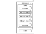
- FIG. 1 is a diagram showing an example of a configuration of a road surface evaluation system including a road surface evaluation device according to the present embodiment.
- the road surface evaluation system 1 includes a road surface evaluation device 10 and an in-vehicle device 30.
- the road surface evaluation device is configured as a server device.
- the in-vehicle device 30 is configured to be able to communicate with the road surface evaluation device 10 via the communication network 2.
- the communication network 2 includes not only public wireless communication networks represented by Internet networks and mobile phone networks, but also closed communication networks provided for each predetermined management area, such as wireless LAN and Wi-Fi (registered trademark). ), Bluetooth®, etc. are also included.
- the in-vehicle device 30 is mounted on various vehicles 20.
- the vehicle 20 includes a vehicle 20-1, a vehicle 20-2, and a vehicle 20-3.
- Vehicle 20-1 and vehicle 20-2 are of the same vehicle type but different grades, and vehicle 20-1 is lower in grade than vehicle 20-2.
- Vehicle 20-3 is a vehicle of a vehicle type different from that of vehicle 20-1 and vehicle 20-2.
- the vehicle 20-3 is a vehicle type in which ride quality is more important than the vehicle types of the vehicle 20-1 and the vehicle 20-2.
- the number of vehicles included in the vehicle 20 is not limited to three, and the vehicle 20 may include vehicles other than the vehicles 20-1 to 20-3.
- FIG. 2 is a block diagram showing a configuration of a main part of the in-vehicle device 30 according to the present embodiment.
- the in-vehicle device 30 includes an electronic control unit (ECU) 31, a positioning sensor 32, an acceleration sensor 33, a steering angle sensor 34, a vehicle speed sensor 35, and a TCU (Telematic Control Unit) 36.
- ECU electronice control unit
- TCU Telematic Control Unit
- the positioning sensor 32 is, for example, a GPS sensor, which receives a positioning signal transmitted from a GPS satellite and detects the absolute position (latitude, longitude, etc.) of the vehicle 20.
- the positioning sensor 32 includes not only a GPS sensor but also a sensor for positioning using radio waves transmitted from satellites of various countries called GNSS satellites such as a quasi-zenith orbit satellite. Further, the vehicle position may be obtained by a hybrid method with inertial navigation.
- the acceleration sensor 33 detects the left-right acceleration of the vehicle 20, that is, the lateral acceleration.
- the acceleration sensor 33 may be configured to detect the acceleration in the front-rear direction and the acceleration in the up-down direction together with the lateral acceleration of the vehicle 20.
- the steering angle sensor 34 detects the steering angle of the steering wheel (not shown) of the vehicle 20.
- the vehicle speed sensor 35 detects the vehicle speed of the vehicle 20.
- the ECU 31 includes a computer having a calculation unit 310 such as a CPU (processor), a storage unit 320 such as a ROM and RAM, and other peripheral circuits (not shown) such as an I / O interface. It is composed.
- the calculation unit 310 functions as a sensor value acquisition unit 311 and a communication control unit 312 by executing a program stored in the storage unit 320 in advance.
- the sensor value acquisition unit 311 acquires information (value) detected by each sensor 32 to 34, that is, running information.
- the sensor value acquisition unit 311 acquires traveling information including the acceleration of the vehicle 20 detected by the acceleration sensor 33 and the absolute position of the vehicle 20 detected by the positioning sensor 32 in a predetermined cycle, for example, every 10 ms.
- the travel information includes at least the lateral acceleration of the vehicle 20 detected by the acceleration sensor 33.
- the communication control unit 312 transmits the travel information acquired by the sensor value acquisition unit 311 to the road surface evaluation device 10 via the TCU 36. At this time, the communication control unit 312 transmits the travel information acquired by the sensor value acquisition unit 311 at a predetermined cycle. More specifically, the communication control unit 312 thins out the travel information acquired by the sensor value acquisition unit 311 so as not to increase the processing load and unnecessarily press the band of the communication network 2. For example, it is transmitted every 1s.
- the road surface evaluation device 10 detects the uneven shape of the road surface, that is, the road surface profile, based on the value detected by the acceleration sensor 33 of the vehicle 20.
- This detected road surface profile is output to, for example, a terminal owned by a road management company or the like, and is used as reference data when the road management company or the like examines the necessity of repair or the like. That is, the detected value of the accelerometer is used to evaluate the road surface profile.
- the road surface evaluation device is configured as follows so that the road surface profile can be sufficiently evaluated.
- FIG. 3 is a block diagram showing a main configuration of the road surface evaluation device 10 according to the present embodiment.
- the road surface evaluation device 10 includes a computer having a calculation unit 110 such as a CPU, a storage unit 120 such as a ROM and a RAM, and other peripheral circuits (not shown) such as an I / O interface.
- the storage unit 120 stores map information including a road map and various information processed by the calculation unit 110.
- the calculation unit 110 functions as an information acquisition unit 111, a road surface profile derivation unit 112, a road surface profile correction unit 113, a road surface profile output unit 114, and a communication control unit 115 by executing a program stored in the storage unit 120. ..
- the information acquisition unit 111 acquires running information including information indicating the motion of the vehicle 20, including acceleration in each direction of the vehicle 20, and position information of the vehicle 20.
- the information acquisition unit 111 receives travel information from the in-vehicle device 30 of the vehicle 20 traveling on the road via the communication control unit 115.
- the information indicating the motion of the vehicle 20 is information in which information indicating the roll motion of the vehicle, information indicating the motion due to centrifugal force, and information indicating the motion due to the unevenness of the road surface are mixed.
- the roll motion is a rotational motion around the axis of the center of gravity in the front-rear direction of the vehicle, that is, a swing motion in the left-right direction of the vehicle.
- the traveling information includes identification information of the vehicle 20 that is the transmission source (hereinafter, referred to as vehicle identification information).
- vehicle identification information is information that can identify at least one of the vehicle type and grade of the vehicle 20, and is, for example, a chassis number.
- the information acquisition unit 111 acquires map information including information on the road on which the vehicle 20 travels from the storage unit 120.
- the information acquisition unit 111 acquires vehicle information including unique information of the vehicle 20.
- the unique information of the vehicle 20 is information that can specify the type or state of a predetermined component constituting the vehicle 20.
- the predetermined parts constituting the vehicle 20 are parts that affect the movement of the vehicle 20 during traveling, and are, for example, suspensions and tires.
- the type of component is, for example, the type of suspension distinguished by spring rate or the like, or the type of tire distinguished by flatness, width, and hardness of rubber.
- the state of a part is a state of a part that changes according to a period of use or the like, and is, for example, the hardness of a suspension or the hardness of a tire. Information that can identify the state of a part is, for example, the year of manufacture of the vehicle.
- the road surface profile derivation unit 112 derives the amount of unevenness (depth or height) of the road surface, that is, the roughness information indicating the road surface roughness, based on the traveling information acquired by the information acquisition unit 111.
- the roughness information is a road surface roughness value indicating the degree of road surface roughness, and is, for example, a value represented by IRI (International Roughness Index), which is an international index.
- IRI International Roughness Index
- the road surface profile deriving unit 112 uses this correlation to derive the road surface roughness value corresponding to the vehicle position on the road from the lateral acceleration. Specifically, the road surface profile derivation unit 112 first derives the correlation between the road surface roughness value and the lateral acceleration based on the previously measured road surface roughness value and the lateral acceleration.
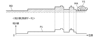
- FIGS. 4A and 4B are diagrams for explaining a method of deriving the correlation between the road surface roughness value and the lateral acceleration.
- the vehicle V1 shown in FIG. 4A is a dedicated vehicle equipped with a measuring device MA for measuring the roughness of the road surface.
- the measuring device MA measures the road surface roughness value of the road RD when the vehicle V1 is traveling on a predetermined road (measurement course or the like) RD.
- the characteristic P1 of FIG. 4A shows the road surface roughness value measured at this time.
- FIG. 4B shows how the vehicle 20 of FIG. 1 travels on the same road RD as that of FIG. 4A.
- the waveform P2 in FIG. 4B shows the lateral acceleration detected every 10 ms by the acceleration sensor 33 provided in the vehicle 20 while the vehicle 20 is traveling on a predetermined road RD.
- the vehicle 20 used for deriving the correlation will be referred to as a reference vehicle.
- the vehicle 20-1 is used as a reference vehicle.
- the road surface profile derivation unit 112 correlates the road surface roughness value and the lateral acceleration based on the road surface roughness value measured using the vehicle V1 and the lateral acceleration measured using the vehicle 20-1 which is a reference vehicle. The relationship is derived, and the information indicating the correlation is stored in the storage unit 120.
- deriving the correlation prepare a plurality of vehicles having the same vehicle type and grade as the vehicle 20-1, and use the lateral acceleration measured from each of the plurality of reference vehicles to derive the correlation. May be good. More specifically, statistical data (average value, etc.) of lateral acceleration measured from each of a plurality of reference vehicles may be used for deriving the correlation. Thereby, the correlation between the road surface roughness value and the lateral acceleration can be derived more accurately.
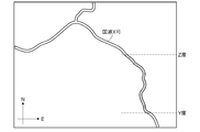
- FIG. 5A is a diagram showing an example of a map of the road on which the vehicle 20 travels.
- FIG. 5A shows a predetermined road (section of latitudes Y to Z of national highway X) to be derived from the road surface roughness value.
- the upward direction corresponds to the north direction
- the right direction corresponds to the east direction.
- the range to be derived from the road surface roughness value can be specified by the user as described later.
- the road to which the road surface roughness value is to be derived is a plurality of lanes on one side, the lane to which the road surface roughness value is to be derived is specified by the user.
- FIG. 1 shows a predetermined road (section of latitudes Y to Z of national highway X) to be derived from the road surface roughness value.
- the upward direction corresponds to the north direction
- the right direction corresponds to the east direction.
- the range to be derived from the road surface roughness value can be specified by the user as described later.
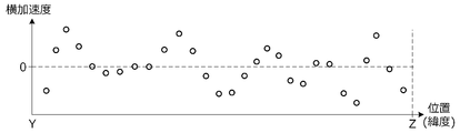
- 5B is a diagram showing an example of traveling information acquired by the road surface evaluation device 10 from the vehicle-mounted device 30 of the vehicle 20 traveling on the predetermined road of FIG. 5A (the section of latitude Y to Z of the national highway X).
- the horizontal axis in the figure is the position (latitude) in the traveling direction along the traveling lane of the vehicle 20, and the vertical axis is the lateral acceleration of the vehicle 20.
- FIG. 6 is a diagram showing an example of a road surface roughness value derived based on travel information acquired from an in-vehicle device 30 of a vehicle 20 traveling on the predetermined road.
- the characteristic P11 shown in FIG. 6 represents a road surface roughness value derived from the traveling information acquired from the in-vehicle device 30 of the vehicle 20-1.
- the characteristic P12 represents a road surface roughness value derived from the traveling information acquired from the in-vehicle device 30 of the vehicle 20-2.
- the characteristic P13 represents a road surface roughness value derived from the traveling information of the vehicle-mounted device 30 of the vehicle 20-3.
- the road surface roughness derived by the road surface profile deriving unit 112 is obtained.
- the value is different.
- the reason is that the parts that affect the movement of the vehicle, such as the suspension and tires mounted on each vehicle, differ depending on the vehicle type and grade.
- the impact absorption performance of suspensions and tires is usually higher as the grade is higher between the same vehicle models, and is higher as the ride quality is emphasized between different vehicle models.
- the characteristic P13 corresponding to the vehicle 20-3 which is a vehicle type in which the ride quality is emphasized, has a lower value than the characteristics P11 and P12 corresponding to the vehicles 20-1 and 20-2. ..
- the characteristic P12 corresponding to the vehicle 20-2 having a higher grade than the vehicle 20-1 has a lower value than the characteristic P11 corresponding to the vehicle 20-1.
- the vehicle type and grade of the vehicle 20 are specified based on the vehicle identification information of the vehicle 20 included in the traveling information. Further, the road surface roughness value derived from the driving information of each vehicle is corrected by using the correction coefficient corresponding to the specified vehicle type and grade.
- FIG. 7 is a diagram showing an example of vehicle information.
- the vehicle information shown in FIG. 7 is created in advance and stored in the storage unit 120.
- the vehicle information includes information indicating the type of suspension and tire of the vehicle and a correction coefficient corresponding to the type in association with the vehicle type and grade of the vehicle.
- the road surface profile correction unit 113 previously drives vehicles 20 having different vehicle types and grades on a predetermined road (road RD in FIG. 4A).
- the road surface profile correction unit 113 determines the correction coefficient corresponding to the type of suspension and tire of each vehicle based on the ratio of the road surface roughness value of each vehicle derived based on the traveling information of each vehicle. In this way, the road surface profile correction unit 113 also functions as a correction coefficient determining unit.
- the road surface profile correction unit 113 stores information (vehicle information shown in FIG. 7) in which the determined correction coefficient is associated with the vehicle type and grade of the vehicle in the storage unit 120.
- the road surface profile correction unit 113 determines the correction coefficient of each vehicle, with the correction coefficient of the vehicle 20-1, which is the reference vehicle, being 1.0. For example, assuming that the vehicle type of vehicle 20-1 is "ABC" and the grade is "standard”, the suspension correction coefficient ⁇ 12 and the tire correction coefficient ⁇ 12 in FIG. 7 are 1.0, respectively.
- the same suspension and tires may be installed on all grades.
- the correction coefficient of the suspension of each grade may be the same value, or the correction coefficient of the tire of each grade may be the same value.
- the same suspension and tires may be installed between different vehicle models, and in such a case, the same correction coefficient is set between different vehicle models. For example, when the suspension "SS_13" is attached to a vehicle of the grade "high” of the vehicle type "XYZ", the correction coefficient of the suspension of the vehicle of the grade "high” of the vehicle type "XYZ" is the grade of the vehicle "ABC". It will be the same ⁇ 13 as the "low” vehicle.
- the road surface profile correction unit 113 corrects the road surface roughness value derived by the road surface profile derivation unit 112. More specifically, first, the road surface profile correction unit 113 determines the vehicle type and grade of the vehicle 20 that is the transmission source of the travel information based on the vehicle identification information of the vehicle 20 included in the travel information acquired by the information acquisition unit 111. Identify. The road surface profile correction unit 113 acquires vehicle information corresponding to the vehicle type and grade from the storage unit 120.
- the road surface profile correction unit 113 acquires the correction coefficient from the vehicle information of the vehicle 20. For example, when the vehicle type of the vehicle 20 is "ABC" and the grade is "low", ⁇ 13 is acquired as the suspension correction coefficient and ⁇ 13 is acquired as the tire correction coefficient.
- the road surface profile correction unit 113 corrects the road surface roughness value by multiplying the read correction coefficient by the road surface roughness value derived by the road surface profile derivation unit 112.
- the road surface profile correction unit 113 stores the corrected road surface roughness value (hereinafter, referred to as a corrected road surface roughness value) in the storage unit 120 in chronological order.
- the road surface profile output unit 114 outputs the corrected road surface roughness value stored in the storage unit 120 in time series in association with the road information acquired by the information acquisition unit 111.
- the communication control unit 115 controls a communication unit (not shown) to send / receive data to / from an external device or the like. More specifically, the communication control unit 115 transmits / receives data to / from a terminal such as an in-vehicle device 30 of the vehicle 20 or a road management company via the communication network 2. Further, the communication control unit 115 receives an output instruction of the road surface profile described later from a terminal of a road management company or the like via the communication network 2. Further, the communication control unit 115 acquires map information and the like from various servers connected to the communication network 2 periodically or at an arbitrary timing. Then, the communication control unit 115 stores the information acquired from various servers in the storage unit 120.
- FIG. 8 is a flowchart showing an example of processing executed by the calculation unit 110 (CPU) of the road surface evaluation device 10 according to a predetermined program. The process shown in this flowchart is repeated at a predetermined cycle while the road surface evaluation device 10 is activated.
- step S11 it is determined whether or not the traveling information is received from the in-vehicle device 30 of the vehicle 20. If denied in step S11, the process proceeds to step S16. If affirmed in step S11, the road surface roughness value is derived in step S12 based on the travel information received in step S11.
- step S13 the vehicle type and grade of the vehicle 20 are specified based on the vehicle identification information included in the travel information received in step S11, and the vehicle information corresponding to the vehicle type and grade is acquired from the storage unit 120.
- step S14 the road surface roughness value derived in step S12 is corrected by the correction coefficient included in the acquired vehicle information, that is, the correction coefficient corresponding to the vehicle type and grade of the vehicle 20.
- step S15 the corrected road surface roughness value (corrected road surface roughness value) is stored in the storage unit 120. At this time, the position information of the vehicle 20 included in the traveling information received in step S11 is stored in the storage unit 120 in association with the corrected road surface roughness value.
- step S16 it is determined whether or not the output instruction of the road surface profile has been input (received).
- the output instruction of the road surface profile is transmitted from a terminal of a user (road management company, etc.) to the road surface evaluation device 10 via the communication network 2, for example.
- the output instruction of the road surface profile may be input to the road surface evaluation device 10 via an operation unit (not shown) included in the road surface evaluation device 10.
- the output instruction of the road surface profile includes section information that can specify the section of the road to be output.
- the section information is information indicating the name and section of the road to be output, such as "road: national highway X, section: latitude Y to Z". If the road has multiple lanes on each side, such as two lanes on each side, the section information includes information on the lane to be output, such as "road: national highway X, lane: right end, section: latitude Y to Z". May be included.
- information other than latitude may be used to specify the section to be output. For example, longitude may be used instead of latitude, or longitude may be used in addition to latitude. Further, the distance from the starting point (for example, the point at the longitude Y of the national highway X) may be used.
- step S16 If denied in step S16, the process ends. If affirmed in step S16, the map information is read from the storage unit 120 in step S17, and the road information included in the map information is acquired. In step S18, the corrected road surface roughness value of the vehicle 20 is acquired from the storage unit 120. More specifically, based on the section information included in the output instruction of the road surface profile and the road information acquired in step S17, the corrected road surface roughness value of the section targeted for output stored in the storage unit 120 is stored. Obtained from the storage unit 120. At this time, the position information of the vehicle 20 stored in the storage unit 120 in association with the corrected road surface roughness value is also acquired.
- step S19 the corrected road surface roughness value acquired in step S18 is output in association with the road information acquired in step S17. More specifically, based on the road information acquired in step S17 and the position information of the vehicle 20 associated with the corrected road surface roughness value, each position of the section targeted for output is acquired in step S18. The corrected road surface roughness value is associated and output.
- the information output at this time is referred to as road surface profile information.
- the road surface profile information is output to a terminal of a transmission source of an output instruction of the road surface profile or a terminal of a predetermined output destination via the communication network 2.
- the road surface profile information is information that can be displayed on a display device such as a display, and the user can confirm or evaluate the road surface profile by displaying the road surface profile information on the display of the user's terminal. Even if it is denied in step S16, if the corrected road surface roughness value that has not been output among the corrected road surface roughness values of the vehicle 20 stored in the storage unit 120 is accumulated in a predetermined amount or more. , You may proceed to step S17. Even if the affirmation is made in step S16, if the corrected road surface roughness value of the vehicle 20 stored in the storage unit 120 but not output is less than a predetermined amount, the process is performed. May be terminated.
- information for notifying that the corrected road surface roughness value that has not been output is less than a predetermined amount is provided to the terminal of the transmission source of the road surface profile output instruction, etc. It may be output to.
- the road surface evaluation device 10 acquires driving information including information indicating the movement of the moving vehicle 20 and position information of the vehicle 20, acquires map information including information on the road on which the vehicle travels, and vehicles. Based on the information acquisition unit 111 that acquires vehicle information including the unique information of 20 and the travel information acquired by the information acquisition unit 111, a roughness value indicating the roughness of the road surface on which the vehicle 20 travels is derived.
- the road surface profile derivation unit 112, the road surface profile correction unit 113 that corrects the roughness value of the road surface derived by the road surface profile derivation unit 112 based on the vehicle information acquired by the information acquisition unit 111, and the road surface profile correction unit 113. It has an output unit that outputs the road surface roughness value corrected by the above method in association with the road information acquired by the information acquisition unit 111 (FIG. 3).
- the road surface evaluation device 10 further includes a storage unit 120 for storing vehicle information.
- the information acquisition unit 111 acquires vehicle information from the storage unit 120 based on the vehicle identification information included in the acquired travel information. As a result, the vehicle information of the moving vehicle 20 can be acquired in real time, and the road surface roughness value can be corrected in real time.
- the unique information of the vehicle 20 includes information regarding the type and grade of the vehicle 20.
- the correction can be performed according to the type and grade of the vehicle 20, and the road surface roughness can be corrected regardless of the type and grade of the vehicle 20.
- the roughness value can be corrected with high accuracy.
- the grade information includes information on at least one type of vehicle suspension and tire.
- the road surface profile correction unit 113 has a road surface profile derivation unit 112 based on travel information acquired from each vehicle when a plurality of vehicles are previously driven on a predetermined road (road RD shown in FIG. 4A). To determine the correction coefficient for correcting the roughness value of the road surface derived by.
- the vehicle information includes a correction coefficient in association with the unique information of the vehicle 20.
- the road surface profile correction unit 113 corrects the roughness value of the road surface derived by the road surface profile derivation unit 112 by using the correction coefficient included in the vehicle information acquired by the information acquisition unit 111. Thereby, when the road surface roughness value derived from the traveling information of the vehicle is corrected, the correction can be performed for each vehicle by using the correction coefficient corresponding to the vehicle. Therefore, even when there are a plurality of traveling vehicles, the road surface roughness value derived from the traveling information of each vehicle can be corrected with high accuracy.
- the road surface evaluation device 10 of the present embodiment can also be used as a road surface evaluation method.
- the road surface evaluation method there is a step of acquiring driving information including information indicating the movement of the moving vehicle 20 and position information of the vehicle 20, and a step of acquiring map information including information on the road on which the vehicle 20 is traveling.
- a computer executes a step of correcting the derived road surface roughness value based on the vehicle information and a step of outputting the corrected road surface roughness value in association with the acquired road information. Including that. Thereby, a road surface profile that can be sufficiently evaluated can be derived regardless of the type of the vehicle 20 traveling on the road.
- the information acquisition unit 111 acquires the lateral acceleration of the vehicle 20 detected by the acceleration sensor 33 as the travel information acquisition unit as information indicating the motion of the vehicle 20.
- the information indicating the motion is not limited to the lateral acceleration of the vehicle 20 detected by the acceleration sensor 33. That is, any configuration of the traveling information acquisition unit may be used as long as the information indicating the motion of the vehicle 20 is acquired.
- the vehicle speed of the vehicle 20 detected by the vehicle speed sensor 35 and the steering angle of the vehicle 20 detected by the steering angle sensor 34 may be acquired as information indicating motion.
- the road surface profile derivation unit 112 derives the road surface roughness value based on the lateral acceleration of the vehicle 20 detected by the acceleration sensor 33 as the roughness value derivation unit.
- the roughness value deriving unit may be used as long as the road surface roughness value of the road on which the vehicle 20 travels is derived.
- the information acquisition unit 111 acquires map information including information on the road on which the vehicle 20 travels as a map information acquisition unit from the storage unit 120, but the map information can be obtained from an external server or the like. It may be stored in an external storage device. That is, any configuration of the map information acquisition unit may be used as long as it acquires map information including information on the road on which the vehicle 20 travels.
- the information acquisition unit 111 acquires vehicle information including the unique information of the vehicle 20 from the storage unit 120 as the vehicle information acquisition unit, but the vehicle information is stored in an external server or an external storage unit. It may be stored in the device. That is, any configuration of the vehicle information acquisition unit may be used as long as it acquires vehicle information including information on the road on which the vehicle 20 travels.
- the road surface profile correction unit 113 uses the correction coefficient as the roughness value correction unit to correct the road surface roughness value derived by the road surface profile derivation unit 112.
- the roughness value correction unit may correct the road surface roughness value by using a correction formula or a table instead of the correction coefficient. That is, any configuration of the roughness value correction unit may be used as long as the road surface roughness value is corrected.
- the road surface profile correction unit 113 corrects the road surface roughness value derived by the road surface profile derivation unit 112 based on the vehicle speed detected by the vehicle speed sensor 35 and the steering angle detected by the steering angle sensor 34. You may do it.
- the acceleration sensor 33 detects not only the lateral acceleration generated by the unevenness of the road surface but also the lateral acceleration generated by the centrifugal force generated according to the speed and steering angle of the vehicle 20. .. Therefore, in such a case, the road surface profile correction unit 113 removes the component based on the lateral acceleration due to the centrifugal force from the road surface roughness value derived based on the lateral acceleration detected by the acceleration sensor 33.
- the road surface roughness value may be corrected. As a result, it is possible to accurately derive the road surface roughness value of a road other than a straight line.
- the road surface profile correction unit 113 may correct the road surface roughness value derived by the road surface profile derivation unit 112 based on the vehicle speed detected by the vehicle speed sensor 35. Even when the vehicle 20 travels on the same road, the lateral acceleration of the vehicle 20 detected by the acceleration sensor 33 changes according to the vehicle speed during traveling. More specifically, the faster the vehicle speed during traveling, the more difficult it is for the tires of the vehicle 20 to follow the road surface, and the smaller the lateral acceleration detected by the acceleration sensor 33.
- the road surface profile correction unit 113 may correct the road surface roughness value derived by the road surface profile derivation unit 112 by using the correction coefficient included in the vehicle information and the correction coefficient according to the vehicle speed.
- the road surface profile correction unit 113 previously drives the vehicle 20 at different vehicle speeds on a predetermined road and measures the difference in the road surface roughness value caused by the difference in the road surface followability of the vehicle 20.
- the road surface profile correction unit 113 determines a correction coefficient according to the vehicle speed of the vehicle 20 based on the measurement result, and stores the correction coefficient in the storage unit 120. With this configuration, the road surface roughness value can be accurately corrected regardless of the vehicle speed of the vehicle 20.
- the road surface profile output unit 114 outputs the road surface profile information to the user's terminal as an output unit, but the output unit outputs the road surface profile information to the map information stored in the storage unit 120.
- the road surface profile information may be output to the storage unit 120 so as to be mapped. That is, any configuration of the output unit may be used as long as the road surface profile information is output.
- the road surface roughness value is represented by IRI
- the road surface roughness value may be represented by another index.
- the road surface profile deriving unit 112 may derive the road surface roughness value represented by the index. ..
- the vehicle information may also include vehicle maintenance information, including information on vehicle suspension or tire replacement. More specifically, when the suspension or tire of the vehicle is replaced, the road surface profile correction unit 113 is newly attached to the vehicle in association with the vehicle identification information of the vehicle in which the suspension or tire is replaced.
- the vehicle information may include information indicating the type of suspension or tire and a correction coefficient corresponding to the type. As a result, even when the suspension or tire of the vehicle is replaced, the road surface roughness value derived from the traveling information of the vehicle can be corrected with high accuracy.
- the road surface profile correction unit 113 puts the vehicle with the replaced suspension or tire on a predetermined road (for example, FIG. 4A). Drive on the road RD).
- the road surface profile correction unit 113 determines a correction coefficient corresponding to the type of newly mounted suspension and tire based on the road surface roughness value derived from the traveling information of the vehicle.
- the predetermined road used when determining the correction coefficient is not limited to the measurement course. If the road surface roughness value has already been derived and the reliability of the road surface roughness value is high (greater than or equal to a predetermined value), even if a general road is used when determining the correction coefficient. good.
- the road surface profile correction unit 113 may correct the road surface roughness value derived by the road surface profile derivation unit 112 based on the state of the suspension and the tire of the vehicle 20.
- the condition of the suspension and tires changes depending on the period of use and the like. Normally, the longer the suspension and tires are used, the lower the impact absorption performance is, and the impact and vibration due to the unevenness of the road surface are easily transmitted to the vehicle.
- the period of use of the suspension and tires of the vehicle 20 can be predicted to some extent from the year of manufacture of the vehicle 20 and the time when the suspension and tires are replaced. Therefore, the road surface profile correction unit 113 specifies the year of manufacture of the vehicle 20 from the vehicle identification information of the vehicle 20.
- the road surface profile correction unit 113 specifies the suspension and tire replacement time from the maintenance information.
- the road surface profile correction unit 113 uses the correction coefficient included in the vehicle information and the correction coefficient according to the year of manufacture of the vehicle 20 and the replacement time of the suspension and tires, and the road surface roughness derived by the road surface profile extraction unit 112.
- the value may be corrected.
- the correction coefficient according to the year of manufacture of the vehicle 20 and the time of replacement of the suspension and tires is set to a larger value as the difference between the year of manufacture and the time of replacement and the present time increases.
Landscapes
- Engineering & Computer Science (AREA)
- Physics & Mathematics (AREA)
- General Physics & Mathematics (AREA)
- Automation & Control Theory (AREA)
- Architecture (AREA)
- Civil Engineering (AREA)
- Structural Engineering (AREA)
- Transportation (AREA)
- Mechanical Engineering (AREA)
- Mathematical Physics (AREA)
- Human Computer Interaction (AREA)
- Road Repair (AREA)
- Traffic Control Systems (AREA)
- Length Measuring Devices With Unspecified Measuring Means (AREA)
Abstract
路面評価装置(10)は、走行中の車両の運動を示す情報と車両の位置情報を含む走行情報を取得し、車両が走行する道路の情報を含む地図情報を取得し、さらに、車両の固有情報を含む車両情報を取得する情報取得部(111)と、情報取得部(111)により取得された走行情報に基づいて、車両が走行する道路の路面の粗さを示す粗さ値を導出する路面プロファイル導出部(112)と、情報取得部(111)により取得された車両情報に基づいて、路面プロファイル導出部(112)により導出された路面の粗さ値を補正する路面プロファイル補正部(113)と、路面プロファイル補正部(113)により補正された路面の粗さ値を、情報取得部(111)により取得された道路の情報に対応付けて出力する出力部(114)と、を有する。
Description
本発明は、路面の凹凸形状を表す路面プロファイルを評価する路面評価装置および路面評価方法に関する。
この種の装置として、従来、車両に設けられた加速度センサにより測定された横方向(走行方向に対する横方向)の加速度に基づいて、車両が走行した道路の路面の凹凸形状を表す路面プロファイルを検出するようにした装置が知られている(例えば特許文献1参照)。
しかしながら、加速度センサにより測定された加速度に基づいて検出される路面プロファイルには、車両のサスペンションやタイヤの種類やそれらの状態によってばらつきが生じる。したがって、上記特許文献1記載の装置のように、単に加速度センサにより測定された加速度に基づいて路面プロファイルを検出するのでは、路面プロファイルを十分に評価することができない。
本発明の一態様である路面評価装置は、走行中の車両の運動を示す情報と車両の位置情報とを含む走行情報を取得する走行情報取得部と、車両が走行する道路の情報を含む地図情報を取得する地図情報取得部と、車両の固有情報を含む車両情報を取得する車両情報取得部と、走行情報取得部により取得された走行情報に基づいて、車両が走行する道路の路面の粗さを示す粗さ値を導出する粗さ値導出部と、車両情報取得部により取得された車両情報に基づいて、粗さ値導出部により導出された路面の粗さ値を補正する粗さ値補正部と、粗さ値補正部により補正された路面の粗さ値を、地図情報取得部により取得された道路の情報に対応付けて出力する出力部と、を有する。
本発明の他の態様である路面評価方法は、走行中の車両の運動を示す情報と車両の位置情報とを含む走行情報を取得するステップと、車両が走行する道路の情報を含む地図情報を取得するステップと、車両の固有情報を含む車両情報を取得するステップと、取得された走行情報に基づいて、車両が走行する道路の路面の粗さを示す粗さ値を導出するステップと、取得された車両情報に基づいて、導出された路面の粗さ値を補正するステップと、補正された路面の粗さ値を、取得された道路の情報に対応付けて出力するステップとを、コンピュータにより実行することを含む。
本発明によれば、路面プロファイルを十分に評価することができる。
以下、図1~図8を参照して本発明の実施形態について説明する。本発明の実施形態に係る路面評価装置は、車両が走行する道路の路面プロファイルを評価するための装置である。図1は、本実施形態に係る路面評価装置を備える路面評価システムの構成の一例を示す図である。図1に示すように、路面評価システム1は、路面評価装置10と、車載装置30とを備える。路面評価装置はサーバ装置として構成される。車載装置30は、通信網2を介して路面評価装置10と通信可能に構成される。
通信網2には、インターネット網や携帯電話網等に代表される公衆無線通信網だけでなく、所定の管理地域ごとに設けられた閉鎖的な通信網、例えば無線LAN、Wi-Fi(登録商標)、Bluetooth(登録商標)等も含まれる。
車載装置30は、種々の車両20に搭載される。車両20には、車両20-1、車両20-2、車両20-3が含まれる。車両20-1および車両20-2は、同じ車種であるがグレードが異なり、車両20-1は、車両20-2よりもグレードが低い。車両20-3は、車両20-1および車両20-2と異なる車種の車両である。車両20-3は、車両20-1および車両20-2の車種よりも乗り心地が重視された車種である。なお、車両20に含まれる車両は3台に限らず、車両20には車両20-1~20-3以外の車両が含まれていてもよい。
図2は、本実施形態に係る車載装置30の要部構成を示すブロック図である。車載装置30は、電子制御ユニット(ECU)31と、測位センサ32と、加速度センサ33と、舵角センサ34と、車速センサ35と、TCU(Telematic Control Unit)36とを有する。
測位センサ32は、例えばGPSセンサであって、GPS衛星から送信された測位信号を受信し、車両20の絶対位置(緯度、経度など)を検出する。なお、測位センサ32には、GPSセンサだけでなく準天頂軌道衛星をはじめとしたGNSS衛星と言われる各国の衛星から送信される電波を利用して測位するセンサも含まれる。また、慣性航法とのハイブリッド手法によって車両位置を求めるようにしても良い。
加速度センサ33は、車両20の左右方向の加速度、すなわち横加速度を検出する。なお、加速度センサ33は、車両20の横加速度とともに前後方向の加速度や上下方向の加速度を検出するように構成されてもよい。舵角センサ34は、車両20のステアリングホイール(不図示)の操舵角を検出する。車速センサ35は、車両20の車速を検出する。
図2に示すように、ECU31は、CPU(プロセッサ)等の演算部310と、ROM、RAM等の記憶部320と、I/Oインターフェース等の図示しないその他の周辺回路とを有するコンピュータを含んで構成される。演算部310は、予め記憶部320に記憶されたプログラムを実行することで、センサ値取得部311および通信制御部312として機能する。
センサ値取得部311は、各センサ32~34により検出される情報(値)、すなわち走行情報を取得する。センサ値取得部311は、加速度センサ33により検出された車両20の加速度と測位センサ32により検出された車両20の絶対位置とを含む走行情報を所定周期で、例えば10msごとに取得する。走行情報には、加速度センサ33により検出された車両20の横加速度が少なくとも含まれる。通信制御部312は、センサ値取得部311により取得された走行情報を、TCU36を介して路面評価装置10に送信する。このとき、通信制御部312は、センサ値取得部311により取得された走行情報を、所定周期で送信する。より具体的には、通信制御部312は、処理負荷を増大させないように、且つ、通信網2の帯域を不要に圧迫しないように、センサ値取得部311により取得された走行情報を間引いて、例えば1sごとに送信する。
路面評価装置10は、車両20の加速度センサ33による検出値に基づいて路面の凹凸形状、すなわち路面プロファイルを検出する。この検出された路面プロファイルは、例えば道路管理会社等が有する端末に出力され、道路管理会社等により補修の要否等を検討する際の参照データとして用いられる。すなわち、加速度センサの検出値が、路面プロファイルを評価するために用いられる。
しなしながら、上述したように、車両の加速度センサにより測定された加速度に基づいて検出される路面プロファイルは、車両のサスペンションやタイヤの種類やそれらの状態によってばらつきが生じる。そのため、車両20が有する加速度センサに基づいて検出された路面プロファイルでは、路面プロファイルの十分な評価を行うことが難しい。そこで、本実施形態では、路面プロファイルを十分に評価可能なように、以下のように路面評価装置を構成する。
図3は、本実施形態に係る路面評価装置10の要部構成を示すブロック図である。路面評価装置10は、CPU等の演算部110と、ROM、RAM等の記憶部120と、I/Oインターフェース等の図示しないその他の周辺回路とを有するコンピュータを含んで構成される。記憶部120は、道路の地図を含む地図情報や演算部110により処理される各種情報を記憶する。
演算部110は、記憶部120に記憶されたプログラムを実行することで、情報取得部111、路面プロファイル導出部112、路面プロファイル補正部113、路面プロファイル出力部114、および通信制御部115として機能する。
情報取得部111は、車両20の各方向の加速度が含まれる、車両20の運動を示す情報と、車両20の位置情報とを含む走行情報を取得する。情報取得部111は、通信制御部115を介して、道路を走行中の車両20の車載装置30から走行情報を受信する。車両20の運動を示す情報とは、車両のロール運動を示す情報と遠心力による運動を示す情報と路面の凹凸による運動を示す情報とが混合された情報である。ロール運動とは、車両の前後方向の重心軸まわりの回転運動、すなわち車両の左右方向の揺動運動である。走行情報には、送信元である車両20の識別情報(以下、車両識別情報と呼ぶ。)が含まれる。車両識別情報は、車両20の車種およびグレードの少なくとも一方を特定可能な情報であり、例えば車台番号である。
情報取得部111は、車両20が走行する道路の情報を含む地図情報を記憶部120から取得する。
情報取得部111は、車両20の固有情報を含む車両情報を取得する。車両20の固有情報は、車両20を構成する所定の部品の種別または状態を特定可能な情報である。車両20を構成する所定の部品とは、走行中の車両20の運動に影響を与える部品であって、例えばサスペンションやタイヤである。また、部品の種別とは、例えば、バネレート等で区別されるサスペンションの種別や、扁平率や幅、ゴムの硬さで区別されるタイヤの種別である。部品の状態とは、使用期間等に応じて変化する部品の状態であり、例えばサスペンションの硬さやタイヤの硬さである。部品の状態を特定可能な情報とは、例えば車両の製造年である。
路面プロファイル導出部112は、情報取得部111により取得された走行情報に基づいて、路面の凹凸の量(深さまたは高さ)、つまり路面粗さを示す粗さ情報を導出する。粗さ情報は、路面の粗さの程度を示す路面粗さ値であり、例えば、国際的な指標であるIRI(国際ラフネス指標)で表される値である。以下、路面粗さ値を単に粗さ値と表現する場合がある。
一般に、路面の凹凸の量が大きいほど車両20の横加速度は大きく、路面粗さ値と横加速度とは所定の相関関係を有する。路面プロファイル導出部112は、この相関関係を用いて、横加速度から道路上の車両位置に対応する路面粗さ値を導出する。具体的には、路面プロファイル導出部112は、まず、予め測定された路面粗さ値と横加速度とに基づいて、路面粗さ値と横加速度との相関関係を導出する。
図4Aおよび図4Bは、路面粗さ値と横加速度との相関関係の導出方法を説明するための図である。図4Aに示す車両V1は、路面の粗さを測定する測定機器MAを搭載する専用車両である。測定機器MAは、所定の道路(測定用コース等)RDを車両V1が走行しているときに、道路RDの路面粗さ値を測定する。図4Aの特性P1は、このとき測定される路面粗さ値を示す。
図4Bには、図1の車両20が図4Aと同一の道路RDを走行する様子が示される。図4Bの波形P2は、車両20が所定の道路RDを走行中に、車両20に設けられた加速度センサ33により10msごとに検出された横加速度を示す。以下、相関関係の導出に用いられた車両20を基準車両と呼ぶ。本実施形態では、車両20-1を基準車両とする。
路面プロファイル導出部112は、車両V1を用いて測定した路面粗さ値と、基準車両である車両20-1を用いて測定した横加速度とに基づいて、路面粗さ値と横加速度との相関関係を導出し、相関関係を示す情報を記憶部120に記憶する。なお、相関関係を導出する際、車両20-1と車種とグレードとが同じ車両を複数台用意して、複数台の基準車両それぞれから測定された横加速度を相関関係の導出に用いるようにしてもよい。より詳細には、複数台の基準車両それぞれから測定された横加速度の統計データ(平均値など)を相関関係の導出に用いるようにしてもよい。それにより、路面粗さ値と横加速度との相関関係をより精度よく導出することができる。
図5Aは、車両20が走行する道路の地図の一例を示す図である。図5Aには、路面粗さ値の導出対象となる所定道路(国道X号の緯度Y~Zの区間)が示される。図5Aにおいて上方向が北方向に対応し、右方向が東方向に対応する。路面粗さ値の導出対象とされる範囲は、後述するようにユーザにより指定可能である。路面粗さ値の導出対象とされる道路が片側複数車線である場合には、路面粗さ値の導出対象とされる車線がユーザにより指定される。図5Bは、図5Aの所定道路(国道X号の緯度Y~Zの区間)を走行した車両20の車載装置30から路面評価装置10が取得した、走行情報の一例を示す図である。図中の横軸は、車両20の走行車線に沿った進行方向の位置(緯度)であり、縦軸は、車両20の横加速度である。
図6は、上記所定道路を走行中の車両20の車載装置30から取得された走行情報に基づいて導出された路面粗さ値の一例を示す図である。図6に示す特性P11は、車両20-1の車載装置30から取得された走行情報から導出された路面粗さ値を表す。特性P12は、車両20-2の車載装置30から取得された走行情報から導出された路面粗さ値を表す。特性P13は、車両20-3の車載装置30走行情報から導出された路面粗さ値を表す。
図6に示されるように、車両20-1,20-2,20-3が同じ道路を走行した場合でも、各車両の車種やグレードが異なると、路面プロファイル導出部112により導出される路面粗さ値が異なる。その理由は、各車両に装着されているサスペンションやタイヤなど、車両の運動に影響を与える部品が車種やグレードごとに異なるためである。
通常、サスペンションやタイヤの衝撃吸収性能(垂直方向の衝撃吸収性能)が低くなるほど、路面の凹凸による衝撃や振動が車両に伝わりやすくなり、車両20の加速度センサ33により検出される横加速度が大きくなる。また、通常、サスペンションやタイヤの衝撃吸収性能は、同じ車種間においてはグレードが高くなるほど高くなり、異なる車種間においては乗り心地が重視された車種ほど高くなる。
したがって、図6に示すように、乗り心地が重視された車種である車両20-3に対応する特性P13は、車両20-1,20-2に対応する特性P11,P12よりも低い値になる。また、図6に示すように、車両20-1よりもグレードが高い車両20-2に対応する特性P12は、車両20-1に対応する特性P11よりも低い値になる。これにより、車両20-1,20-2,20-3が同一の道路を走行した場合でも、各車両の走行情報(横加速度)から導出される路面粗さ値にばらつきが発生する。このように走行情報から導出される路面粗さ値が車両20の車種やグレードによって変化すると、路面粗さ値を十分に評価できなくなる。
この点を考慮して、本実施形態では、走行情報に含まれる車両20の車両識別情報に基づいて、車両20の車種やグレードを特定する。さらに、特定した車種やグレードに対応する補正係数を用いて、各車両の走行情報から導出された路面粗さ値を補正する。
図7は、車両情報の一例を示す図である。図7に示す車両情報は、予め作成され記憶部120に記憶される。車両情報は、車両の車種およびグレードに対応付けて、車両のサスペンションおよびタイヤの種別を示す情報とその種別に対応する補正係数とを含む。
路面プロファイル補正部113は、予め、車種やグレードがそれぞれ異なる車両20を所定の道路(図4Aの道路RD)で走行させる。路面プロファイル補正部113は、各車両の走行情報に基づき導出された各車両の路面粗さ値の比に基づいて、各車両のサスペンションおよびタイヤの種別に対応する補正係数を決定する。このように、路面プロファイル補正部113は、補正係数決定部としても機能する。
路面プロファイル補正部113は、決定した補正係数を車両の車種およびグレードに対応付けた情報(図7に示す車両情報)を、記憶部120に記憶する。なお、路面プロファイル補正部113は、基準車両である車両20-1の補正係数を1.0として、各車両の補正係数を決定する。例えば車両20-1の車種が「ABC」でありグレードが「標準」であるとすると、図7のサスペンションの補正係数α12およびタイヤの補正係数β12はそれぞれ1.0となる。
上述したように、サスペンションやタイヤの衝撃吸収性能は、通常、同じ車種間においてはグレードが高くなるほど高くなり、異なる車種間においては乗り心地が重視された車種ほど高くなる。したがって、図7に示す例において車種「ABC」が車種「XYZ」よりも乗り心地が重視された車種であるとすると、サスペンションの補正係数α11,α12,α13,α21の大小関係は、α13>α12(=1.0)>α11>α21となる。同様に、タイヤの補正係数β11,β12,β13,β21の大小関係は、β13>β12(=1.0)>β11>β21となる。
なお、車種によっては、全てのグレードに同一のサスペンションやタイヤが装着される場合がある。そのような場合には、各グレードのサスペンションの補正係数が同じ値になったり、各グレードのタイヤの補正係数が同じ値になったりする。また、異なる車種間で同一のサスペンションやタイヤが装着される場合もあり、そのような場合には、異なる車種間でも同一の補正係数が設定される。例えば、車種「XYZ」のグレード「高」の車両にサスペンション「SS_13」が装着される場合には、車種「XYZ」のグレード「高」の車両のサスペンションの補正係数は、車種「ABC」のグレード「低」の車両と同じα13となる。
路面プロファイル補正部113は、路面プロファイル導出部112により導出された路面粗さ値を補正する。より詳しくは、まず、路面プロファイル補正部113は、情報取得部111により取得された走行情報に含まれる車両20の車両識別情報に基づいて、走行情報の送信元である車両20の車種およびグレードを特定する。路面プロファイル補正部113は、その車種およびグレードに対応する車両情報を記憶部120から取得する。
次いで、路面プロファイル補正部113は、車両20の車両情報から補正係数を取得する。例えば、車両20の車種が「ABC」でありグレードが「低」である場合には、サスペンションの補正係数としてα13が取得され、タイヤの補正係数としてβ13が取得される。
最後に、路面プロファイル補正部113は、読み出した補正係数を、路面プロファイル導出部112により導出された路面粗さ値に乗算して、路面粗さ値を補正する。路面プロファイル補正部113は、補正した路面粗さ値(以下、補正後路面粗さ値と呼ぶ。)を記憶部120に時系列に記憶する。
路面プロファイル出力部114は、記憶部120に時系列に記憶された補正後路面粗さ値を、情報取得部111により取得された道路の情報に対応付けて出力する。
通信制御部115は、不図示の通信部を制御して、外部の装置等とデータの送受信を行う。より詳しくは、通信制御部115は、通信網2を介して、車両20の車載装置30や道路管理会社等の端末と、データの送受信を行う。また、通信制御部115は、通信網2を介して、道路管理会社等の端末から後述する路面プロファイルの出力指示を受信する。また、通信制御部115は、通信網2に接続された各種サーバから、地図情報などを定期的に、あるいは任意のタイミングで取得する。そして、通信制御部115は、各種サーバから取得した情報を記憶部120に記憶する。
図8は、予め定められたプログラムに従い路面評価装置10の演算部110(CPU)で実行される処理の一例を示すフローチャートである。このフローチャートに示す処理は、路面評価装置10が起動している間、所定周期で繰り返される。まず、ステップS11で、車両20の車載装置30から走行情報を受信したか否かを判定する。ステップS11で否定されると、ステップS16に進む。ステップS11で肯定されると、ステップS12で、ステップS11で受信した走行情報に基づいて路面粗さ値を導出する。
ステップS13で、ステップS11で受信した走行情報に含まれる車両識別情報に基づいて車両20の車種およびグレードを特定し、その車種およびグレードに対応する車両情報を記憶部120から取得する。ステップS14で、取得した車両情報に含まれる補正係数、すなわち車両20の車種およびグレードに対応する補正係数で、ステップS12で導出した路面粗さ値を補正する。ステップS15で、補正した路面粗さ値(補正後路面粗さ値)を記憶部120に記憶する。このとき、補正後路面粗さ値に対応付けて、ステップS11で受信した走行情報に含まれる車両20の位置情報を記憶部120に記憶する。
ステップS16で、路面プロファイルの出力指示を入力(受信)したか否かを判定する。路面プロファイルの出力指示は、例えばユーザ(道路管理会社等)の端末から通信網2を介して路面評価装置10に対して送信される。なお、路面プロファイルの出力指示は、路面評価装置10が有する操作部(不図示)を介して路面評価装置10に入力可能であってもよい。
路面プロファイルの出力指示には、出力対象とする道路の区間を特定可能な区間情報が含まれる。区間情報は、例えば、「道路:国道X号線、区間:緯度Y~Z」といったように、出力対象とする道路の名称と区間とを示す情報である。なお、道路が片側2車線など片側複数車線である場合には、「道路:国道X号線、車線:右端、区間:緯度Y~Z」といったように、区間情報に出力対象とする車線の情報が含まれてもよい。また、出力対象とする区間の指定には、緯度以外の情報が用いられてもよい。例えば、緯度の代わりに経度が用いられてもよいし、緯度に加えて経度が用いられてもよい。また、始点(例えば、国道X号線の経度Yの地点)からの距離が用いられてもよい。
ステップS16で否定されると、処理を終了する。ステップS16で肯定されると、ステップS17で、記憶部120から地図情報を読み出し、地図情報に含まれる道路の情報を取得する。ステップS18で、記憶部120から車両20の補正後路面粗さ値を取得する。より詳しくは、路面プロファイルの出力指示に含まれる区間情報とステップS17で取得した道路の情報とに基づいて、記憶部120に記憶された、出力対象とされた区間の補正後路面粗さ値を記憶部120から取得する。このとき、補正後路面粗さ値に対応付けて記憶部120に記憶された車両20の位置情報も取得する。
最後に、ステップS19で、ステップS18で取得した補正後路面粗さ値を、ステップS17で取得された道路の情報に対応付けて出力する。より詳しくは、ステップS17で取得した道路の情報と、補正後路面粗さ値に対応付けられた車両20の位置情報とに基づいて、出力対象とされた区間の各位置に、ステップS18で取得した補正後路面粗さ値を対応付けて出力する。以下、このとき出力される情報を路面プロファイル情報と呼ぶ。路面プロファイル情報は、通信網2を介して、路面プロファイルの出力指示の送信元の端末や、予め定められた出力先の端末に出力される。路面プロファイル情報はディスプレイ等の表示装置に表示可能な情報であり、ユーザは、ユーザの端末が有するディスプレイに路面プロファイル情報を表示させることで、路面プロファイルを確認したり評価したりすることができる。なお、ステップS16で否定された場合でも、記憶部120に記憶された車両20の補正後路面粗さ値のうち出力されていない補正後路面粗さ値が所定量以上蓄積されている場合には、ステップS17に進むようにしてもよい。また、ステップS16で肯定された場合でも、記憶部120に記憶された車両20の補正後路面粗さ値のうち出力されていない補正後路面粗さ値が所定量未満である場合には、処理を終了してもよい。その際、出力されていない補正後路面粗さ値が所定量未満であることを通知するための情報(テキスト情報や、音声情報、画像情報)を、路面プロファイルの出力指示の送信元の端末等に出力してもよい。
本発明の実施形態によれば以下のような作用効果を奏することができる。
(1)路面評価装置10は、走行中の車両20の運動を示す情報と車両20の位置情報とを含む走行情報を取得し、車両が走行する道路の情報を含む地図情報を取得し、車両20の固有情報を含む車両情報を取得する情報取得部111と、情報取得部111により取得された走行情報に基づいて、車両20が走行する道路の路面の粗さを示す粗さ値を導出する路面プロファイル導出部112と、情報取得部111により取得された車両情報に基づいて、路面プロファイル導出部112により導出された路面の粗さ値を補正する路面プロファイル補正部113と、路面プロファイル補正部113により補正された路面の粗さ値を、情報取得部111により取得された道路の情報に対応付けて出力する出力部と、を有する(図3)。
(1)路面評価装置10は、走行中の車両20の運動を示す情報と車両20の位置情報とを含む走行情報を取得し、車両が走行する道路の情報を含む地図情報を取得し、車両20の固有情報を含む車両情報を取得する情報取得部111と、情報取得部111により取得された走行情報に基づいて、車両20が走行する道路の路面の粗さを示す粗さ値を導出する路面プロファイル導出部112と、情報取得部111により取得された車両情報に基づいて、路面プロファイル導出部112により導出された路面の粗さ値を補正する路面プロファイル補正部113と、路面プロファイル補正部113により補正された路面の粗さ値を、情報取得部111により取得された道路の情報に対応付けて出力する出力部と、を有する(図3)。
この構成により、道路を走行する車両20の種別に依らずに、十分に評価可能な路面プロファイルを導出することができる。また、路面プロファイル測定用の専用車両等を用いずに一般車両の走行情報を用いて、道路の路面プロファイルを十分に評価することが可能となる。さらに、道路管理会社等のユーザは、現地に行くことなく路面評価装置10により出力された路面プロファイルに基づいて補修が必要な道路を推測することができ、道路管理に要する費用を削減することが可能となる。
(2)路面評価装置10は、車両情報を記憶する記憶部120をさらに備える。情報取得部111は、取得した走行情報に含まれる車両識別情報に基づいて車両情報を記憶部120から取得する。これにより、走行中の車両20の車両情報をリアルタイムで取得することができ、路面粗さ値の補正をリアルタイムで行うことが可能となる。
(3)車両20の固有情報は、車両20の種別とグレードに関する情報を含む。これにより、車両20の走行情報から導出された路面粗さ値を補正する際に、車両20の種別とグレードに応じた補正を行うことができ、車両20の種別やグレードに依らずに路面粗さ値を精度よく補正することができる。
(4)グレードに関する情報は、車両のサスペンションおよびタイヤの少なくとも一方の種別に関する情報を含む。これにより、車両の走行情報から導出された路面粗さ値を補正する際に、車両に装着されたサスペンションやタイヤの種別に応じた補正を行うことができ、車両に装着されたサスペンションやタイヤの種別に依らずに路面粗さ値を精度よく補正することができる。
(5)路面プロファイル補正部113は、予め、複数の車両を所定の道路(図4Aに示す道路RD)で走行させたときに各車両から取得された走行情報に基づいて、路面プロファイル導出部112により導出された路面の粗さ値を補正するための補正係数を決定する。車両情報は、車両20の固有情報に対応付けて補正係数を含む。路面プロファイル補正部113は、情報取得部111により取得された車両情報に含まれる補正係数を用いて、路面プロファイル導出部112により導出された路面の粗さ値を補正する。これにより、車両の走行情報から導出された路面粗さ値を補正する際に、車両ごとにその車両に対応する補正係数を用いて補正を行うことができる。よって、走行中の車両が複数存在するときでも、各車両の走行情報から導出された路面粗さ値をそれぞれ精度よく補正することができる。
(6)本実施形態の路面評価装置10は、路面評価方法として用いることもできる。路面評価方法においては、走行中の車両20の運動を示す情報と車両20の位置情報とを含む走行情報を取得するステップと、車両20が走行する道路の情報を含む地図情報を取得するステップと、車両20の固有情報を含む車両情報を取得するステップと、取得された走行情報に基づいて、車両20が走行する道路の路面の粗さを示す粗さ値を導出するステップと、取得された車両情報に基づいて、導出された路面の粗さ値を補正するステップと、補正された路面の粗さ値を、取得された道路の情報に対応付けて出力するステップとを、コンピュータにより実行することを含む。これにより、道路を走行する車両20の種別に依らずに、十分に評価可能な路面プロファイルを導出することができる。
上記実施形態は種々の形態に変形することができる。以下、変形例について説明する。上記実施形態では、情報取得部111が、走行情報取得部として加速度センサ33により検出された車両20の横加速度を車両20の運動を示す情報として取得するようにした。しかし、運動を示す情報は、加速度センサ33により検出された車両20の横加速度に限らない。すなわち、車両20の運動を示す情報を取得するのであれば、走行情報取得部の構成はいかなるものでもよい。例えば、車速センサ35により検出された車両20の車速と舵角センサ34により検出された車両20の舵角とを運動を示す情報として取得してもよい。
また、上記実施形態では、路面プロファイル導出部112が、粗さ値導出部として加速度センサ33により検出された車両20の横加速度に基づいて、路面粗さ値を導出するようにした。しかし、車両20が走行する道路の路面粗さ値を導出するのであれば、粗さ値導出部の構成はいかなるものでもよい。
また、上記実施形態では、情報取得部111が、地図情報取得部として車両20が走行する道路の情報を含む地図情報を記憶部120から取得するようにしたが、地図情報は、外部のサーバや外部の記憶装置に記憶されてもよい。すなわち、車両20が走行する道路の情報を含む地図情報を取得するのであれば、地図情報取得部の構成はいかなるものでもよい。
また、上記実施形態では、情報取得部111が、車両情報取得部として車両20の固有情報を含む車両情報を記憶部120から取得するようにしたが、車両情報は、外部のサーバや外部の記憶装置に記憶されてもよい。すなわち、車両20が走行する道路の情報を含む車両情報を取得するのであれば、車両情報取得部の構成はいかなるものでもよい。
また、上記実施形態では、路面プロファイル補正部113が、粗さ値補正部として補正係数を用いて、路面プロファイル導出部112により導出された路面の粗さ値を補正するようにした。しかし、粗さ値補正部は、補正係数ではなく、補正用の式やテーブルを用いて路面粗さ値を補正してもよい。すなわち、路面粗さ値を補正するのであれば、粗さ値補正部の構成はいかなるものでもよい。
また、路面プロファイル補正部113は、路面プロファイル導出部112により導出された路面粗さ値を、車速センサ35により検出された車速と舵角センサ34により検出された舵角とに基づいて補正するようにしてもよい。カーブしている道路を車両20が走行するとき、加速度センサ33は、路面の凹凸により発生する横加速度だけでなく、車両20の速度や舵角に応じて発生する遠心力による横加速度を検出する。そこで、そのような場合には、路面プロファイル補正部113は、加速度センサ33により検出された横加速度に基づき導出された路面粗さ値から、遠心力による横加速度に基づく成分を排除するように、路面粗さ値を補正してもよい。それにより、直線以外の道路の路面粗さ値についても精度よく導出することが可能となる。
また、路面プロファイル補正部113は、路面プロファイル導出部112により導出された路面粗さ値を、車速センサ35により検出された車速に基づいて補正するようにしてもよい。車両20が同じ道路を走行した場合でも、走行時の車速に応じて加速度センサ33により検出される車両20の横加速度が変化する。より詳しくは、走行時の車速が早くなるほど、車両20のタイヤが路面に追随しづらくなり、加速度センサ33により検出される横加速度が小さくなるためである。
そこで、路面プロファイル補正部113は、車両情報に含まれる補正係数と、車速に応じた補正係数とを用いて、路面プロファイル導出部112により導出された路面粗さ値を補正してもよい。その場合、路面プロファイル補正部113は、予め、所定の道路で車両20を異なる車速で走行させて、車両20の路面追随性の差により生じる路面粗さ値の差を測定する。路面プロファイル補正部113は、その測定結果に基づいて車両20の車速に応じた補正係数を決定し、その補正係数を記憶部120に記憶させておく。この構成により、車両20の車速に依らずに路面粗さ値を精度よく補正することができる。
また、上記実施形態では、路面プロファイル出力部114が、出力部として路面プロファイル情報をユーザの端末に出力するようにしたが、出力部は、路面プロファイル情報が記憶部120に記憶された地図情報にマッピングされるように、路面プロファイル情報を記憶部120に出力してもよい。すなわち、路面プロファイル情報を出力するのであれば、出力部の構成はいかなるものでもよい。
また、上記実施形態では、路面粗さ値がIRIで表される例を示したが、路面粗さ値は、他の指標で表されてもよい。例えば、教師データとして取得される路面粗さ値がIRI以外の指標で表される場合には、路面プロファイル導出部112は、その指標で表された路面粗さ値を導出するようにしてもよい。
また、車両情報は、車両のサスペンションまたはタイヤの交換に関する情報を含む車両の整備情報を含んでもよい。より詳しくは、車両のサスペンションまたはタイヤの交換が行われた場合には、路面プロファイル補正部113は、サスペンションまたはタイヤが交換された車両の車両識別情報に対応付けて、車両に新たに装着されたサスペンションまたはタイヤの種別を示す情報とその種別に対応する補正係数とを車両情報に含ませてもよい。これにより、車両のサスペンションやタイヤが交換された場合でも、車両の走行情報から導出された路面粗さ値を精度よく補正することができる。なお、交換されたサスペンションまたはタイヤの種別に対応する補正係数が車両情報に含まれない場合には、路面プロファイル補正部113は、サスペンションまたはタイヤの交換された車両を所定の道路(例えば、図4Aの道路RD)で走行させる。路面プロファイル補正部113は、その車両の走行情報から導出された路面粗さ値に基づいて、新たに装着されたサスペンションおよびタイヤの種別に対応する補正係数を決定する。
また、補正係数を決定する際に使用する所定の道路は、測定用コースに限らない。路面粗さ値が既に導出されていて、且つ、その路面粗さ値の信頼度が高い(所定値以上である)道路であれば、補正係数を決定する際に一般の道路を使用してもよい。
さらに、路面プロファイル補正部113は、路面プロファイル導出部112により導出された路面粗さ値を、車両20のサスペンションやタイヤの状態に基づいて補正するようにしてもよい。サスペンションやタイヤの状態は、使用期間等に応じて変化する。通常、サスペンションやタイヤは、使用期間が長くなるほど衝撃吸収性能が低下し、路面の凹凸による衝撃や振動が車両に伝わりやすくなる。車両20のサスペンションやタイヤの使用期間は、車両20の製造年やサスペンションやタイヤの交換時期からある程度予測することができる。そこで、路面プロファイル補正部113は、車両20の車両識別情報から車両20の製造年を特定する。または、路面プロファイル補正部113は、整備情報からサスペンションやタイヤの交換時期を特定する。路面プロファイル補正部113は、車両情報に含まれる補正係数と、車両20の製造年やサスペンションやタイヤの交換時期に応じた補正係数とを用いて、路面プロファイル導出部112により導出された路面粗さ値を補正するようにしてもよい。例えば、車両20の製造年やサスペンションやタイヤの交換時期に応じた補正係数は、製造年や交換時期と現時点との差が大きくなるほど大きい値に設定される。
以上の説明はあくまで一例であり、本発明の特徴を損なわない限り、上述した実施形態および変形例により本発明が限定されるものではない。上記実施形態と変形例の一つまたは複数を任意に組み合わせることも可能であり、変形例同士を組み合わせることも可能である。
10 路面評価装置、20,20-1~20-3 車両、30 車載装置、110 演算部、111 情報取得部、112 路面プロファイル導出部(粗さ値導出部)、113 路面プロファイル補正部(粗さ値補正部)、114 路面プロファイル出力部(出力部)、120 記憶部
Claims (9)
- 走行中の車両の運動を示す情報と車両の位置情報とを含む走行情報を取得する走行情報取得部と、
車両が走行する道路の情報を含む地図情報を取得する地図情報取得部と、
車両の固有情報を含む車両情報を取得する車両情報取得部と、
前記走行情報取得部により取得された走行情報に基づいて、車両が走行する道路の路面の粗さを示す粗さ値を導出する粗さ値導出部と、
前記車両情報取得部により取得された前記車両情報に基づいて、前記粗さ値導出部により導出された前記路面の粗さ値を補正する粗さ値補正部と、
前記粗さ値補正部により補正された前記路面の粗さ値を、前記地図情報取得部により取得された道路の情報に対応付けて出力する出力部と、を有することを特徴とする路面評価装置。 - 請求項1に記載の路面評価装置において、
前記車両情報を記憶する記憶部をさらに備え、
前記走行情報取得部により取得された走行情報には、車両識別情報が含まれ、
前記車両情報取得部は、前記走行情報取得部により取得された走行情報に含まれる前記車両識別情報に基づいて前記車両情報を前記記憶部から取得することを特徴とする路面評価装置。 - 請求項2に記載の路面評価装置において、
前記車両識別情報は、車両の車種とグレードを特定可能な情報であり、
前記車両情報取得部は、前記走行情報取得部により取得された走行情報に含まれる前記車両識別情報に基づいて、前記走行中の車両に対応する前記車両情報を前記記憶部から取得することを特徴とする路面評価装置。 - 請求項1~3のうちのいずれか1項に記載の路面評価装置において、
前記固有情報は、車両の種別とグレードに関する情報を含むことを特徴とする路面評価装置。 - 請求項4に記載の路面評価装置において、
前記グレードに関する情報は、車両のサスペンションおよびタイヤの少なくとも一方の種別に関する情報を含むことを特徴とする路面評価装置。 - 請求項1~5のうちのいずれか1項に記載の路面評価装置において、
前記車両情報は、さらに車両の整備情報を含み、
前記整備情報は、車両のサスペンションおよびタイヤの少なくとも一方の交換に関する情報を含むことを特徴とする路面評価装置。 - 請求項1~6のうちのいずれか1項に記載の路面評価装置において、
複数の車両を所定の道路で走行させたときに各車両から取得された走行情報に基づいて、前記粗さ値導出部により導出された前記路面の粗さ値を補正するための補正係数を決定する補正係数決定部をさらに備え、
前記車両情報は、前記固有情報に対応付けて、前記補正係数決定部により決定された補正係数を含み、
前記粗さ値補正部は、前記車両情報取得部により取得された前記車両情報に含まれる補正係数に基づいて、前記粗さ値導出部により導出された前記路面の粗さ値を補正することを特徴とする路面評価装置。 - 請求項7に記載の路面評価装置において、
前記補正係数決定部は、前記粗さ値導出部により、前記各車両から取得された走行情報に基づき導出された、前記各車両の前記路面の粗さ値の比に基づいて、前記補正係数を決定することを特徴とする路面評価装置。 - 走行中の車両の運動を示す情報と車両の位置情報とを含む走行情報を取得するステップと、
車両が走行する道路の情報を含む地図情報を取得するステップと、
車両の固有情報を含む車両情報を取得するステップと、
取得された走行情報に基づいて、車両が走行する道路の路面の粗さを示す粗さ値を導出するステップと、
取得された前記車両情報に基づいて、導出された前記路面の粗さ値を補正するステップと、
補正された前記路面の粗さ値を、取得された道路の情報に対応付けて出力するステップとを、コンピュータにより実行することを含むことを特徴とする路面評価方法。
Priority Applications (2)
| Application Number | Priority Date | Filing Date | Title |
|---|---|---|---|
| US17/927,206 US20230243113A1 (en) | 2020-05-28 | 2021-05-19 | Road surface evaluation apparatus and road surface evaluation method |
| JP2022526927A JP7469468B2 (ja) | 2020-05-28 | 2021-05-19 | 路面評価装置および路面評価方法 |
Applications Claiming Priority (2)
| Application Number | Priority Date | Filing Date | Title |
|---|---|---|---|
| JP2020093108 | 2020-05-28 | ||
| JP2020-093108 | 2020-05-28 |
Publications (1)
| Publication Number | Publication Date |
|---|---|
| WO2021241350A1 true WO2021241350A1 (ja) | 2021-12-02 |
Family
ID=78744587
Family Applications (1)
| Application Number | Title | Priority Date | Filing Date |
|---|---|---|---|
| PCT/JP2021/018956 WO2021241350A1 (ja) | 2020-05-28 | 2021-05-19 | 路面評価装置および路面評価方法 |
Country Status (3)
| Country | Link |
|---|---|
| US (1) | US20230243113A1 (ja) |
| JP (1) | JP7469468B2 (ja) |
| WO (1) | WO2021241350A1 (ja) |
Families Citing this family (1)
| Publication number | Priority date | Publication date | Assignee | Title |
|---|---|---|---|---|
| US20230184563A1 (en) * | 2021-12-14 | 2023-06-15 | GM Global Technology Operations LLC | Connected vehicle-based road surface quality determination |
Citations (2)
| Publication number | Priority date | Publication date | Assignee | Title |
|---|---|---|---|---|
| JP2015184816A (ja) * | 2014-03-20 | 2015-10-22 | Jx日鉱日石エネルギー株式会社 | 評価サーバ |
| WO2018025341A1 (ja) * | 2016-08-03 | 2018-02-08 | 三菱電機株式会社 | 道路状態診断システム、診断用情報生成装置及び診断用情報生成方法 |
-
2021
- 2021-05-19 US US17/927,206 patent/US20230243113A1/en active Pending
- 2021-05-19 JP JP2022526927A patent/JP7469468B2/ja active Active
- 2021-05-19 WO PCT/JP2021/018956 patent/WO2021241350A1/ja active Application Filing
Patent Citations (2)
| Publication number | Priority date | Publication date | Assignee | Title |
|---|---|---|---|---|
| JP2015184816A (ja) * | 2014-03-20 | 2015-10-22 | Jx日鉱日石エネルギー株式会社 | 評価サーバ |
| WO2018025341A1 (ja) * | 2016-08-03 | 2018-02-08 | 三菱電機株式会社 | 道路状態診断システム、診断用情報生成装置及び診断用情報生成方法 |
Also Published As
| Publication number | Publication date |
|---|---|
| JP7469468B2 (ja) | 2024-04-16 |
| US20230243113A1 (en) | 2023-08-03 |
| JPWO2021241350A1 (ja) | 2021-12-02 |
Similar Documents
| Publication | Publication Date | Title |
|---|---|---|
| KR101912109B1 (ko) | 노면에서 단기적 불규칙성의 검출 | |
| JP5269024B2 (ja) | 路面状況推定装置および路面状況推定方法 | |
| US20100211249A1 (en) | System and method for detecting vehicle maintenance requirements | |
| US9043125B2 (en) | Device and process for vehicle driving evaluation | |
| AU2020203601A1 (en) | Mileage and speed estimation | |
| CN110316197B (zh) | 倾斜估算方法、倾斜估算装置以及存储程序的非暂时性计算机可读存储介质 | |
| US11117589B2 (en) | System and method for determining roadway bank angle | |
| CN108931794A (zh) | 一种盲区车辆定位系统及其控制方法 | |
| US11530932B2 (en) | Method of characterizing the condition of a road | |
| WO2021241350A1 (ja) | 路面評価装置および路面評価方法 | |
| CN109387374B (zh) | 一种车道保持水平评价方法 | |
| WO2022059636A1 (ja) | 路面評価装置および路面評価方法 | |
| CN113793509B (zh) | 基于运动传感器的路况分析方法、装置、设备及介质 | |
| US11276255B2 (en) | Mileage and speed estimation | |
| JP2018205970A (ja) | 路面情報収集システム | |
| WO2023153433A1 (ja) | 路面評価装置 | |
| JP7273943B1 (ja) | 路面評価装置 | |
| JP7335317B2 (ja) | 路面評価装置 | |
| JP7037736B2 (ja) | 路面情報収集システム | |
| JP2018205972A (ja) | 路面情報収集システム | |
| CN110211384B (zh) | 基于车车通讯的路况实现方法 | |
| WO2022014357A1 (ja) | 路面評価装置および路面評価方法 | |
| JP2006039642A (ja) | 車両保険料策定および中古車価格策定のための方法およびシステム | |
| CN115143933A (zh) | 轨道线路高低不平顺检测方法、装置及车载轨道检测系统 |
Legal Events
| Date | Code | Title | Description |
|---|---|---|---|
| 121 | Ep: the epo has been informed by wipo that ep was designated in this application |
Ref document number: 21811809 Country of ref document: EP Kind code of ref document: A1 |
|
| ENP | Entry into the national phase |
Ref document number: 2022526927 Country of ref document: JP Kind code of ref document: A |
|
| NENP | Non-entry into the national phase |
Ref country code: DE |
|
| 122 | Ep: pct application non-entry in european phase |
Ref document number: 21811809 Country of ref document: EP Kind code of ref document: A1 |