WO2021240912A1 - 球体駆動式移動装置 - Google Patents
球体駆動式移動装置 Download PDFInfo
- Publication number
- WO2021240912A1 WO2021240912A1 PCT/JP2021/005932 JP2021005932W WO2021240912A1 WO 2021240912 A1 WO2021240912 A1 WO 2021240912A1 JP 2021005932 W JP2021005932 W JP 2021005932W WO 2021240912 A1 WO2021240912 A1 WO 2021240912A1
- Authority
- WO
- WIPO (PCT)
- Prior art keywords
- sphere
- driving
- rotating body
- contact
- center
- Prior art date
- Legal status (The legal status is an assumption and is not a legal conclusion. Google has not performed a legal analysis and makes no representation as to the accuracy of the status listed.)
- Ceased
Links
Images


Classifications
-
- B—PERFORMING OPERATIONS; TRANSPORTING
- B62—LAND VEHICLES FOR TRAVELLING OTHERWISE THAN ON RAILS
- B62D—MOTOR VEHICLES; TRAILERS
- B62D15/00—Steering not otherwise provided for
-
- B—PERFORMING OPERATIONS; TRANSPORTING
- B62—LAND VEHICLES FOR TRAVELLING OTHERWISE THAN ON RAILS
- B62D—MOTOR VEHICLES; TRAILERS
- B62D57/00—Vehicles characterised by having other propulsion or other ground- engaging means than wheels or endless track, alone or in addition to wheels or endless track
-
- B—PERFORMING OPERATIONS; TRANSPORTING
- B60—VEHICLES IN GENERAL
- B60K—ARRANGEMENT OR MOUNTING OF PROPULSION UNITS OR OF TRANSMISSIONS IN VEHICLES; ARRANGEMENT OR MOUNTING OF PLURAL DIVERSE PRIME-MOVERS IN VEHICLES; AUXILIARY DRIVES FOR VEHICLES; INSTRUMENTATION OR DASHBOARDS FOR VEHICLES; ARRANGEMENTS IN CONNECTION WITH COOLING, AIR INTAKE, GAS EXHAUST OR FUEL SUPPLY OF PROPULSION UNITS IN VEHICLES
- B60K1/00—Arrangement or mounting of electrical propulsion units
- B60K1/02—Arrangement or mounting of electrical propulsion units comprising more than one electric motor
Definitions
- the present invention relates to a sphere-driven moving device capable of rotationally driving a sphere to move in all directions.
- a moving device having three or more spheres and three or more driving means (driving motors) for applying a rotational force to the spheres can move in all directions, an electric wheelchair, a self-propelled trolley, etc. It is effective to use for.
- two rotors each of which is rotationally driven by the drive of a driving means, are in contact with one sphere from different directions.
- the rotor and the sphere are in contact with each other at the same height as the center of the sphere, and an idler (wheel type caster) for pressing the sphere against the rotor is provided.
- an idler wheel type caster
- the rotor may be in a non-contact state with the sphere.
- the user controls the mobile device such as when the mobile device is used for an electric wheelchair, it is easy for the user to correct the movement direction by himself, but when the mobile device is used for a self-propelled trolley, the mobile device is used.
- the moving direction of the mobile device cannot be corrected, which causes a problem that the mobile device cannot travel as planned.
- the present invention has been made in view of such circumstances, and an object of the present invention is to provide a sphere-driven moving device capable of suppressing idling of a rotating body that is rotationally driven by a drive source in a state of being in contact with the sphere. ..
- the sphere-driven moving device is rotated by a drive source in a state where four drive spheres each rolling on a traveling surface are in contact with each of the drive spheres from two different directions.
- the traveling surface is a horizontal plane and the center of each driving sphere is four.
- a virtual inverted building roof-like pentahedron having one side surface and a bottom surface arranged at a position higher than the center of each driving sphere, and a top portion away from the bottom surface arranged at a position lower than the center of each driving sphere.
- each rotating body Located on each side, each rotating body has a rotation axis perpendicular to the one side surface, and is located higher than the center of the driving sphere in contact with the one side surface as a corresponding side surface.
- the driving sphere is in contact with the inside of the virtual inverted building roof-like pentahedron or on the corresponding side surface.
- a sphere-driven moving device that includes three or more rotating bodies that are rotationally driven by a drive source to rotate the driving sphere in a state of being in contact with each driving sphere from two different directions, and that moves on the traveling surface.
- each driving sphere has four side surfaces and a bottom surface arranged at a position higher than the center of each driving sphere, and the apex away from the bottom surface is the center of each driving sphere.
- each rotating body Located on different sides of a virtual inverted building roof-like pentahedron located at a lower position, each rotating body has a rotation axis perpendicular to the one side surface, and the one side surface corresponds to the corresponding side surface.
- the driving sphere is in contact with the driving sphere at a position higher than the center of the driving sphere in contact with the driving sphere, and inside the virtual inverted building roof-like pentahedron or on the corresponding side surface.
- the sphere-driven moving device is a state in which two or more driving spheres rolling on a traveling surface and each of the driving spheres are in contact with each other from two different directions by a driving source.
- a sphere-driven moving device that includes three or more rotating bodies that are rotationally driven to rotate the driving sphere and that move on the traveling surface, the rotating bodies are in the shape of a cone and are in contact with each other. The side surface comes into contact with the driving sphere at a position higher than the center of the driving sphere.
- the load of the sphere-driven moving device itself or the sphere driving
- the load of the object mounted on the moving device is applied to the driving sphere via the rotating body, the rotating body can be reliably pressed against the driving sphere, and the rotating body is rotationally driven by the drive source in contact with the driving sphere. It is possible to suppress the rotating body from spinning.
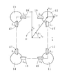
- the sphere-driven moving device 10 has four drive spheres 11, 12, 13, and 14, which roll on the traveling surface G, respectively.
- the drive spheres 11, 12, 13, 14 are rotationally driven by motors 20, 22, 24, 26, which are examples of drive sources, in contact with the drive spheres 11, 12, 13, and 14 from two different directions.
- the driving spheres 11, 12, 13, and 14 are true spheres of the same size (same diameter) as shown in FIGS. 1, 2, 13, and 3, and are counterclockwise when viewed in a plan view. It is arranged around.
- the center P1 of the drive sphere 11, the center P2 of the drive sphere 12, the center P3 of the drive sphere 13, and the center P4 of the drive sphere 14 have the travel surface G as a horizontal plane, and the drive spheres 11, 12, 13, and 14 are on the travel surface G. It is located at the same height when placed in.
- the traveling surface G is a horizontal plane and the driving spheres 11, 12, 13, and 14 are placed on the traveling surface G.
- FIG. 3 shows a plan view of the driving spheres 11, 12, 13, 14 and the rotating bodies 15, 15', 16, 16', 17, 17', 18, 18'and the like.
- the rotating bodies 15, 15', 16, 16', 17, 17', 18, and 18' are cone-shaped members having the same size and the same shape, and are arranged at the same height position.
- the side surface 19 of the rotating body 15 is in contact with the driving sphere 11, and the side surface 19'of the rotating body 15'is in contact with the driving sphere 12.
- the rotating bodies 15 and 15' are connected by a power transmission means having a chain, a pulley or the like (not shown, the same applies hereinafter), are rotationally driven by a motor 20 attached to the rotating body 15, and have the same rotational speed in the same direction. Rotate with.
- the side surface 21 of the rotating body 16 is in contact with the driving sphere 12, and the side surface 21'of the rotating body 16'is in contact with the driving sphere 13.
- the side surface 23 of the rotating body 17 is in contact with the driving sphere 13, and the side surface 23'of the rotating body 17'is in contact with the driving sphere 14.
- the side surface 25 of the rotating body 18 is in contact with the driving sphere 14, and the side surface 25'of the rotating body 18'is in contact with the driving sphere 11.
- the rotating bodies 18 and 18' are connected by a power transmission means, driven to rotate by a motor 26 attached to the rotating body 18, and rotate in the same direction at the same rotation speed.
- the drive spheres 11, 12, 13, and 14 are in contact with ball casters (which may be idlers) that position the drive spheres 11, 12, 13, and 14, respectively.
- the motors 20, 22, 24, and 26 are attached to a base member 27 (see FIGS. 1 and 2) that supports the ball casters.
- the contacts where the drive sphere 11 and the side surface 19 of the rotating body 15 and the side surface 25'of the rotating body 18'contact are referred to as contacts T15 and T18', respectively, and the side surface 21 of the driving sphere 12 and the rotating body 16 and the side surface 19 of the rotating body 15'.
- the contacts with which'contacts are T26 and T25', respectively, and the contacts with which the side surface 23 of the driving sphere 13 and the rotating body 17 and the side surface 21'of the rotating body 16' contact are contact points T37 and T36', respectively.
- the contacts T15, T18', T26, T25', T37, T36', T48, T47' which are in contact with the side surface 25 of the rotating body 18 and the side surface 23'of the rotating body 17', are the contacts T48 and T47', respectively. It is arranged at the same height at a position higher than the center P1 of the drive sphere 11, the center P2 of the drive sphere 12, the center P3 of the drive sphere 13, and the center P4 of the drive sphere 14.
- the degree of freedom in arranging the rotating body 15 with respect to the driving sphere 11 can be increased. If the rotating body 15 is cylindrical, in order to bring the side surface 19 of the rotating body 15 into contact with the driving sphere 11, the rotation axis of the rotating body 15 is set to a virtual straight line J1 passing through the center P1 of the driving sphere 11 and the contact point T15. It is necessary to arrange it so as to be orthogonal to an example of the virtual straight line J).
- the rotating axis does not need to be orthogonal to the virtual straight line J1 passing through the center P1 of the driving sphere 11 and the contact point T15, and the direction of the rotating body 15 with respect to the virtual straight line J1 is It can be adjusted by adjusting the angle of the side surface 19 with respect to the upper surface and the bottom surface of the rotating body 15. Therefore, the rotation axis of the rotating body 15 can be arranged in a desired direction. The same applies to the rotating bodies 15', 16, 16', 17, 17', 18, 18'.
- the four side surfaces a, b, c, and d, the center P1 of the drive sphere 11, the center P2 of the drive sphere 12, the center P3 of the drive sphere 13, and the drive It has a rectangular (rectangular or square) bottom surface e arranged at a position higher than the center P4 of the sphere 14, and the apex O away from the bottom surface e is the center P1 of the drive sphere 11, the center P2 of the drive sphere 12, and the drive.
- the sphere-driven moving device 10 Assuming that the pentagonal roof-like pentahedron H arranged at a position lower than the center P3 of the sphere 13 and the center P4 of the driving sphere 14 is a virtual inverted ridge roof-like pentahedron H, in this embodiment, the sphere-driven moving device 10 However, it is designed to satisfy all of the conditions 1 to 6 described later.
- the four vertices of the bottom surface e are the vertices A, B, C, and D, respectively, and the side surface a is a quadrangle having both ends of the vertices A, B, and the apex O as the four vertices.
- the side surface b is a triangle having three vertices at one end of the vertices B, C and the apex O (an isosceles triangle in this embodiment)
- the side surface c is the vertices C, D and the apex.
- the side surface d is a triangle having three vertices at the other ends of the vertices A and D and the apex O (an isosceles triangle in this embodiment).
- the linear side connecting the other end of the apex O and the apex A is a side side S1
- the linear side connecting one end of the apex O and the apex B is a side side S2
- one end of the apex O and the apex C is a quadrangle having four vertices at both ends of the side O (a trapezoid in this embodiment)
- the side surface d is a triangle having three vertices at the other ends of the vertices A and D and the apex O (an isosceles triangle in this embodiment).
- the linear side connecting the two is referred to as the side side S3, and the linear side connecting the other end of the apex O and the apex D is referred to as the side side S4.
- the bottom surface e is rectangular, and the side sides S1, S2, S3, and S4 have the same length.
- the center P1 of the drive sphere 11, the center P2 of the drive sphere 12, the center P3 of the drive sphere 13, and the center P4 of the drive sphere 14 are located on the side sides S1, S2, S3, and S4, respectively.
- the bodies 16 and 15' contact the drive sphere 12 inside the virtual inverted hipped roof-like pentahedron H (contact points T26 and T25'are located inside the virtual inverted hipped roof-like pentahedron H), and the rotating bodies 17 and 16' 'Is in contact with the drive sphere 13 inside the virtual inverted hipped roof-like pentahedron H (contacts T37 and T36' are located inside the virtual inverted hipped roof-like pentahedron H), and the rotating bodies 18 and 17'are virtual inverted. It is in contact with the drive sphere 14 inside the hipped roof-like pentahedron H (contact points T48 and T47'are located inside the virtual inverted hipped roof-like pentahedron H).
- each rotation axis is perpendicular to the side surface a (one side surface of the virtual inverted building roof-like pentahedron H), and in the rotating bodies 16 and 16', each rotation axis is the side surface b. It is perpendicular to (one side surface of the virtual inverted building roof-like pentahedron H), and each rotation axis of the rotating bodies 17 and 17'is on the side surface c (one side surface of the virtual inverted building roof-like pentahedron H).
- the rotating bodies 18 and 18' are perpendicular to each other, and each rotation axis is perpendicular to the side surface d (one side surface of the virtual inverted building roof-like pentahedron H).
- the side surface a in which the rotation axes of the rotating bodies 15 and 15'are vertical is the corresponding side surface of the rotating bodies 15 and 15', and the rotation axes of the rotating bodies 16 and 16'are vertical.
- the side surface b is the corresponding side surface of the rotating bodies 16 and 16', and the side surface c where the rotation axes of the rotating bodies 17 and 17'are vertical is the corresponding side surface of the rotating bodies 17 and 17'.
- the side surface d on which the axes of rotation of the rotating bodies 18 and 18'are vertical is the corresponding side surface of the rotating bodies 18 and 18'.
- the rotation axes of the rotating bodies 15 and 18'that are in contact with the driving sphere 11 are non-parallel
- the rotation axes of the rotating bodies 16 and 15'that are in contact with the driving sphere 12 are non-parallel. It can be said that the rotation axes of the rotating bodies 17 and 16 ′ in contact with the driving sphere 13 are non-parallel, and the rotating axes of the rotating bodies 18 and 17 ′ in contact with the driving sphere 14 are non-parallel.
- the drive sphere 11 skids with respect to the rotating bodies 15, 18'
- the driving sphere 12 skids with respect to the rotating bodies 16, 15'
- the rotating bodies 17, 16' The sphere-driven moving device 10 can be moved in any direction on the traveling surface G in a state where the sideslip of the drive sphere 13 with respect to the vehicle and the sideslip of the drive sphere 14 with respect to the rotating bodies 18 and 17'are suppressed.
- the side slip of the drive sphere 11 with respect to the rotating body 15 in a state where the rotating body 18'is rotating and applying a rotational force to the driving sphere 11 is relative to the rotating body 15 of the driving sphere 11 at the contact point T15.
- the movement is other than the turning movement around the contact point T15, and when the driving sphere 11 skids with respect to the rotating body 15, the wear of the rotating body 15 and the driving sphere 11 is promoted.
- the rotating bodies 15 and 18' are in contact with the driving sphere 11 at a position higher than the center P1 of the driving sphere 11, the force of the vertical component acts on the driving sphere 11 through the rotating bodies 15 and 18'.
- the rotating bodies 16 and 15'for the driving sphere 12 the rotating bodies 17 and 16'for the driving sphere 13, and the rotating bodies 18 and 17'for the driving sphere 14. Therefore, the rotating bodies 15 and 18'are used as the driving sphere 11 and the rotating bodies 16 and 15' are used as the driving sphere 12 and the rotating body 17 by utilizing the weight of the base member 27 and the heavy objects mounted on the base member 27.
- 16' can be pressed against the driving sphere 13 and the rotating bodies 18 and 17'can be pressed against the driving sphere 14, respectively. It can be suppressed.
- the rotating bodies 15 and 15' are located on the side surface a of the virtual inverted building roof-like pentahedron H. Even if the driving spheres 11 and 12 are in contact with each other on the (corresponding side surface), the driving spheres 11 and the driving spheres 12 do not substantially slide sideways with respect to the rotating body 15 and the rotating body 15', respectively. The same applies to the relationship between the rotating bodies 16, 16'and the driving spheres 12, 13, the rotating bodies 17, 17'and the driving spheres 13, 14, and the rotating bodies 18, 18'and the driving spheres 14, 11.
- Condition 2' The rotating bodies 15 and 15'contact the driving spheres 11 and 12 on the side surface a (corresponding side surface of the rotating bodies 15 and 15') of the virtual inverted building roof-like pentahedron H, respectively, and the rotating bodies 16 and 16'contacts the driving spheres 12 and 13 on the side surface b (corresponding side surface of the rotating bodies 16 and 16') of the virtual inverted building roof-like pentahedron H, and the rotating bodies 17 and 17'are the virtual inverted building roof.
- the rotating bodies 18 and 18' are in contact with the driving spheres 13 and 14 on the side surface c (corresponding side surface of the rotating bodies 17 and 17'), respectively, and the rotating bodies 18 and 18'are on the side surface d of the virtual inverted building roof-like pentahedron H (the corresponding side surface).
- the drive spheres 14 and 11 are in contact with each other on the corresponding side surfaces of the rotating bodies 18 and 18', respectively.
- the passing virtual straight line J18'(an example of the virtual straight line J) is orthogonal to the side side S1 where the center P1 of the driving sphere 11 is located, as shown in FIGS. 1 and 2.
- the virtual straight line J25'(an example of the virtual straight line J) passing through the center P2 of the driving sphere 12 is orthogonal to the side side S2 where the center P2 of the driving sphere 12 is located.
- the virtual straight line J36'(an example of the virtual straight line J) passing through the center P3 of the driving sphere 13 is orthogonal to the side side S3 where the center P3 of the driving sphere 13 is located.
- a virtual straight line J48 (an example of a virtual straight line J) passing through a contact point T48 between the drive sphere 14 and the rotating body 18 and a center P4 of the driving sphere 14, and a contact point T47'and a driving sphere 14 between the driving sphere 14 and the rotating body 17'.
- the virtual straight line J47'(an example of the virtual straight line J) passing through the center P4 of the driving sphere 14 is orthogonal to the side side S4 where the center P4 of the driving sphere 14 is located.
- Condition 5 The contact point T15 between the driving sphere 11 and the rotating body 15 and the virtual straight line J15 passing through the center P1 of the driving sphere 11 intersect the side surface 19 of the rotating body 15 perpendicularly, and the contact point between the driving sphere 11 and the rotating body 18'.
- the virtual straight line J18'passing through the center P1 of the T18'and the driving sphere 11 intersects the side surface 25' of the rotating body 18' perpendicularly.
- the virtual straight line J26 passing through the contact point T26 between the drive sphere 12 and the rotating body 16 and the center P2 of the driving sphere 12 intersects the side surface 21 of the rotating body 16 perpendicularly, and the contact point T25'and the contact point T25' between the driving sphere 12 and the rotating body 15'and The virtual straight line J25'passing through the center P2 of the driving sphere 12 intersects the side surface 19'of the rotating body 15' perpendicularly.
- the virtual straight line J37 passing through the contact point T37 between the drive sphere 13 and the rotating body 17 and the center P3 of the driving sphere 13 intersects the side surface 23 of the rotating body 17 perpendicularly, and the contact point T36'and the contact point T36' between the driving sphere 13 and the rotating body 16'and The virtual straight line J36'passing through the center P3 of the drive sphere 13 intersects the side surface 21'of the rotating body 16'vertically.
- the virtual straight line J48 passing through the contact point T48 between the drive sphere 14 and the rotating body 18 and the center P4 of the driving sphere 14 intersects the side surface 25 of the rotating body 18 perpendicularly, and the contact point T47'and the contact point T47' between the driving sphere 14 and the rotating body 17'and The virtual straight line J47'passing through the center P4 of the driving sphere 14 intersects the side surface 23'of the rotating body 17'perpendicularly.
- the side surface a of the virtual inverted building roof-like pentahedron H has two driving spheres 11 and 12 having centers P1 and P2 arranged on two side sides S1 and S2 forming a part of the outer edge of the side surface a, respectively.
- the side surface b is a rotating body 16 or 16'between two driving spheres 12 and 13 having centers P2 and P3 arranged on two side sides S2 and S3 forming a part of the outer edge of the side surface b, respectively (rotation here).
- An example of a virtual straight line K23 (an example of a virtual straight line K) passing through a contact point T26 between the body 16) and one driving sphere 12 and a contact point T36' between the rotating bodies 16 and 16'(here, the rotating body 16') and the other driving sphere 13. ) Is parallel.
- the side surface c is a rotating body 17 or 17'between two driving spheres 13 and 14 having centers P3 and P4 arranged on two side sides S3 and S4 forming a part of the outer edge of the side surface c, respectively (rotation here).
- An example of a virtual straight line K34 (an example of a virtual straight line K) passing through a contact point T37 between the body 17) and one driving sphere 13 and a contact point T47' between the rotating bodies 17, 17'(here, the rotating body 17') and the other driving sphere 14. ) Is parallel.
- the side surface d is a rotating body 18 or 18'between two driving spheres 14 and 11 having centers P4 and P1 arranged on two side sides S4 and S1 forming a part of the outer edge of the side surface d, respectively (rotation here).
- An example of a virtual straight line K41 (an example of a virtual straight line K) passing through a contact point T48 between the body 18) and one driving sphere 14 and a contact point T18'between the rotating bodies 18 and 18'(here, the rotating body 18') and the other driving sphere 11. ) Is parallel.
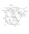
- each value of the sphere-driven mobile device 10 is defined as follows. That is, as shown in FIG. 4, the driving sphere is from the center of the rectangle (hereinafter referred to as "mechanism center") having the centers P1, P2, P3, and P4 of the driving spheres 11, 12, 13, and P4 as the four vertices.
- the distances to the centers P1, P2, P3, and P4 of 11, 12, 13, and 14 are set to l, respectively, and the center of the mechanism and the centers P1, P2, P3, and P4 of the driving spheres 11, 12, 13, and 14 are connected, respectively.
- the angles formed by the line segment and the x-axis are ⁇ 1 , ⁇ 2 , ⁇ 3 , and ⁇ 4 , respectively.
- v x and v y be the x-axis direction component and the y-axis direction component of the translational movement velocity at the center of the mechanism, respectively.
- the counterclockwise rotation direction of the sphere-driven moving device 10 is the positive direction
- the rotation speed at the center of the mechanism is ⁇ .
- ⁇ be the inclination angle of the side surfaces a, b, c, and d of the virtual inverted hipped roof-like pentahedron H with respect to the traveling surface G.
- the angular speed of the driving sphere 14 when the rotating body 17 is stopped and the rotating body 18 is rotated is obtained, and based on the result, the driving when the rotating body 17 is rotated while the rotating body 18 is stopped is obtained.
- the angular velocity of the sphere 14 and the angular velocity of the other driving spheres 11, 12, and 13 are derived.
- the radius of the drive sphere 14 is R, and as shown in FIG. 5, the radius of the portion of the truncated cone-shaped rotating body 18 in contact with the drive sphere 14 (the portion corresponding to the contact point T48) is r.
- the contact point T48 is arranged at the position of Rcos 2 ⁇ inward from the side surface d of the virtual inverted hipped roof-like pentahedron H and at the position of Rcos ⁇ above the center P4 of the drive sphere 14.
- the radius of gyration of the driving sphere 14 at the contact point between the traveling surface G and the driving sphere 14 is Rsin ⁇ , so that is, the peripheral speed of the driving sphere 14 at the contact point between the traveling surface G and the driving sphere 14, that is, driving.
- the moving speed v x4 of the sphere 14 in the x direction is expressed by the following equation (2).
- each side surface of the virtual inverted building roof-like pentahedron is determined. If the tilt angle is fixed, there is an advantage that it is not necessary to change the size and shape of each rotating body even if the ratio of the length of the short side and the length of the long side of the rectangle whose four vertices are the centers of each driving sphere is changed. be.
- each driving sphere and each rotating body is determined based on the virtual inverted quadrangular pyramid with the quadrangular pyramid turned upside down instead of the virtual inverted ridge roof-like pentahedron, the center of each driving sphere is used. It is necessary to change the shape of each rotating body according to the ratio of the lengths of the short side and the long side of the rectangle having four vertices.
- the sphere-driven moving device 10 In the sphere-driven moving device 10 described so far, two rotating bodies (for example, rotating bodies 15 and 15'between the driving spheres 11 and 12) are provided between adjacent driving spheres, and a total of eight rotations are provided. Although it has a body, the number of rotating bodies provided between adjacent driving spheres may be one, and the rotating bodies may come into contact with both of the adjacent driving spheres. In this case, the rotating bodies are in total. It will be four. Therefore, in the sphere-driven moving device in which the rotating bodies are brought into contact with each of the four driving spheres from two different directions, the minimum total number of the rotating bodies is four.
- the sphere-driven moving device 10 includes four driving spheres, whereas the sphere-driven moving device has omnidirectional translational movement and clockwise movement and clockwise movement if it has two or three driving spheres. It is possible to turn counterclockwise.
- each driving sphere has four side surfaces and each with the traveling surface as a horizontal plane. It has a bottom surface located higher than the center of the drive sphere, and the apex away from the bottom surface is located on different sides of the virtual inverted building roof-like pentahedron located lower than the center of each drive sphere.
- the axis of rotation is perpendicular to one side surface, and the one side surface is used as the corresponding side surface, at a position higher than the center of the driving sphere in contact with the rotating body, and inside the virtual inverted building roof-like pentahedron. Alternatively, it contacts the driving sphere on the corresponding side surface.
- the rotating body and its rotating axis are arranged as described above with respect to the virtual inverted building-like pentahedron. It is not necessary that the rotating body is in contact with the driving sphere at a position higher than the center of the driving sphere in contact with the rotating body. In this case, in order to increase the degree of freedom in arranging each rotating body, it is preferable to make the rotating body whose side surface contacts the driving sphere into a truncated cone shape.
- the sphere-driven moving device that suppresses the idling of the rotating body and increases the degree of freedom in the arrangement of the rotating body is driven in a state where two or more driving spheres are in contact with each driving sphere from two different directions. It is a device that includes three or more rotating bodies that are rotationally driven by a source to rotate the driving sphere, and moves on the traveling surface. Each rotating body has a conical table shape and is in contact with the driving sphere. The side surface touches the driving sphere at a position higher than the center of the.
- the sphere-driven moving device in order to put a heavy object on the sphere-driven moving device, it is preferable to have four driving spheres rather than three. Then, in the sphere-driven moving device, in order to make the entire device compact, it is preferable to bring each rotating body into contact with only one driving sphere. This is because it is necessary to use a rotating body having a large diameter in order to bring one rotating body into contact with two driving spheres. Therefore, when four driving spheres are provided, the number of rotating bodies is eight.
- one motor rotates and drives one rotating body (the number of motors and rotating bodies is the same) from the viewpoint of compactification of the entire device.
- the design is preferred. This is because when one motor rotationally drives two rotating bodies, it is necessary to adopt a motor having a large volume. Therefore, when eight rotating bodies are provided, it is preferable that each of the eight motors rotationally drives a different rotating body.
- the rotating body does not have to be a truncated cone, and may be, for example, cylindrical or spherical.
- the rotating shaft of the rotating body may be a shaft member (that is, an existing member) or a virtual shaft.
- each driving sphere may be different, and the size and shape of each rotating body may be different. Then, with each driving sphere placed on a horizontal plane, each rotating body may be arranged so that the height at which each rotating body is in contact with the driving sphere is different. Further, the present invention is also applicable to a spherically driven moving device (for example, a spherically driven moving device that can only move forward and backward) in which a moving direction on a traveling surface is specified.
- a spherically driven moving device for example, a spherically driven moving device that can only move forward and backward
- the sphere-driven moving device according to the present invention can be used as a self-propelled device for carrying an object because it can stably perform a predetermined movement by suppressing idling of a rotating body in contact with the sphere. Can be done.
Landscapes
- Engineering & Computer Science (AREA)
- Chemical & Material Sciences (AREA)
- Combustion & Propulsion (AREA)
- Transportation (AREA)
- Mechanical Engineering (AREA)
- Friction Gearing (AREA)
- Telescopes (AREA)
- Warehouses Or Storage Devices (AREA)
- Toys (AREA)
Priority Applications (4)
| Application Number | Priority Date | Filing Date | Title |
|---|---|---|---|
| CN202180029487.4A CN115485182B (zh) | 2020-05-26 | 2021-02-17 | 球体驱动式移动装置 |
| JP2022527512A JP7487969B2 (ja) | 2020-05-26 | 2021-02-17 | 球体駆動式移動装置 |
| US17/921,445 US12539929B2 (en) | 2020-05-26 | 2021-02-17 | Mobile device with spherical drive system |
| DE112021002961.4T DE112021002961T5 (de) | 2020-05-26 | 2021-02-17 | Mobile Vorrichtung mit Kugelantriebssystem |
Applications Claiming Priority (2)
| Application Number | Priority Date | Filing Date | Title |
|---|---|---|---|
| JP2020091308 | 2020-05-26 | ||
| JP2020-091308 | 2020-05-26 |
Publications (1)
| Publication Number | Publication Date |
|---|---|
| WO2021240912A1 true WO2021240912A1 (ja) | 2021-12-02 |
Family
ID=78744268
Family Applications (1)
| Application Number | Title | Priority Date | Filing Date |
|---|---|---|---|
| PCT/JP2021/005932 Ceased WO2021240912A1 (ja) | 2020-05-26 | 2021-02-17 | 球体駆動式移動装置 |
Country Status (5)
| Country | Link |
|---|---|
| US (1) | US12539929B2 (https=) |
| JP (1) | JP7487969B2 (https=) |
| CN (1) | CN115485182B (https=) |
| DE (1) | DE112021002961T5 (https=) |
| WO (1) | WO2021240912A1 (https=) |
Citations (6)
| Publication number | Priority date | Publication date | Assignee | Title |
|---|---|---|---|---|
| JP2000126241A (ja) * | 1998-10-26 | 2000-05-09 | Matsushita Electric Works Ltd | 電動車椅子および記録媒体 |
| JP2001354156A (ja) * | 2000-06-14 | 2001-12-25 | Kawasaki Heavy Ind Ltd | 球状駆動輪を用いる全方向移動装置 |
| JP2001354155A (ja) * | 2000-06-14 | 2001-12-25 | Kawasaki Heavy Ind Ltd | 全方向移動装置の制御装置 |
| JP2010030360A (ja) * | 2008-07-25 | 2010-02-12 | Kyushu Institute Of Technology | 球体駆動式全方向移動装置 |
| JP2010173570A (ja) * | 2009-01-30 | 2010-08-12 | Kyushu Institute Of Technology | 球体駆動式全方向移動装置 |
| JP2015117011A (ja) * | 2014-12-09 | 2015-06-25 | リーフ株式会社 | 球体駆動モジュール及びそれを使用した自走台車 |
Family Cites Families (6)
| Publication number | Priority date | Publication date | Assignee | Title |
|---|---|---|---|---|
| JPH0690980A (ja) | 1991-11-19 | 1994-04-05 | Osamu Funahashi | 球状車輪を使った駆動により真横方向にも移動可能な車椅子 |
| JP2004024329A (ja) | 2002-06-21 | 2004-01-29 | Yoichi Toyoda | 球体駆動装置 |
| JP4756360B2 (ja) | 2006-06-27 | 2011-08-24 | トヨタ自動車株式会社 | 球体輪駆動機構 |
| JP2009234524A (ja) * | 2008-03-28 | 2009-10-15 | Sony Corp | 搬送装置と駆動機構 |
| US20100243342A1 (en) | 2009-03-25 | 2010-09-30 | Chia-Wen Wu | Omni-wheel based drive mechanism |
| DE112019005925T5 (de) | 2018-11-28 | 2021-10-14 | Kyushu Institute Of Technology | Bewegungsvorrichtung vom Kugelkörper-Antriebstyp |
-
2021
- 2021-02-17 JP JP2022527512A patent/JP7487969B2/ja active Active
- 2021-02-17 CN CN202180029487.4A patent/CN115485182B/zh active Active
- 2021-02-17 US US17/921,445 patent/US12539929B2/en active Active
- 2021-02-17 WO PCT/JP2021/005932 patent/WO2021240912A1/ja not_active Ceased
- 2021-02-17 DE DE112021002961.4T patent/DE112021002961T5/de active Granted
Patent Citations (6)
| Publication number | Priority date | Publication date | Assignee | Title |
|---|---|---|---|---|
| JP2000126241A (ja) * | 1998-10-26 | 2000-05-09 | Matsushita Electric Works Ltd | 電動車椅子および記録媒体 |
| JP2001354156A (ja) * | 2000-06-14 | 2001-12-25 | Kawasaki Heavy Ind Ltd | 球状駆動輪を用いる全方向移動装置 |
| JP2001354155A (ja) * | 2000-06-14 | 2001-12-25 | Kawasaki Heavy Ind Ltd | 全方向移動装置の制御装置 |
| JP2010030360A (ja) * | 2008-07-25 | 2010-02-12 | Kyushu Institute Of Technology | 球体駆動式全方向移動装置 |
| JP2010173570A (ja) * | 2009-01-30 | 2010-08-12 | Kyushu Institute Of Technology | 球体駆動式全方向移動装置 |
| JP2015117011A (ja) * | 2014-12-09 | 2015-06-25 | リーフ株式会社 | 球体駆動モジュール及びそれを使用した自走台車 |
Also Published As
| Publication number | Publication date |
|---|---|
| DE112021002961T5 (de) | 2023-04-27 |
| JP7487969B2 (ja) | 2024-05-21 |
| JPWO2021240912A1 (https=) | 2021-12-02 |
| CN115485182B (zh) | 2025-05-09 |
| US20230174176A1 (en) | 2023-06-08 |
| CN115485182A (zh) | 2022-12-16 |
| US12539929B2 (en) | 2026-02-03 |
Similar Documents
| Publication | Publication Date | Title |
|---|---|---|
| CN112739606B (zh) | 球体驱动式移动装置 | |
| JP3661894B2 (ja) | 球体移動装置 | |
| EP1942046A2 (en) | Drive type of spherical roller | |
| JP2012166297A (ja) | ロボットハンド及びロボット装置 | |
| JP2009113135A (ja) | 2足型移動機構 | |
| JP5305285B2 (ja) | 球体駆動式全方向移動装置 | |
| CN206067368U (zh) | 全向轮、包括全向轮的机器人移动平台及移动机器人 | |
| CN106873645B (zh) | 可全向进动的球形陀螺机构及控制方法 | |
| JP2004237975A (ja) | 羽ばたき装置 | |
| CN106427390A (zh) | 全向轮、包括全向轮的机器人移动平台及移动机器人 | |
| CN103597249B (zh) | 次摆线驱动机构和移动体 | |
| WO2021240912A1 (ja) | 球体駆動式移動装置 | |
| US10730346B2 (en) | Caster apparatus and transferring apparatus including the same | |
| JP2016182912A (ja) | 球状車輪 | |
| CN107139646B (zh) | 一种球形的全向轮及使用该轮的车辆 | |
| CN108215654A (zh) | 车轮和运输车 | |
| JP7161754B2 (ja) | 移動走行装置 | |
| JPWO2021240912A5 (https=) | ||
| JP6066166B2 (ja) | 全方向移動車両 | |
| KR100299622B1 (ko) | 전방향 이동 로봇 | |
| TW201430241A (zh) | 面對面配置之全向輪傳動裝置 | |
| KR20170099683A (ko) | 안정된 자세를 유지하는 볼 로봇 | |
| CN223457683U (zh) | 一种万向运输平台 | |
| JPH01216761A (ja) | バフ装置 | |
| JP5186242B2 (ja) | 揺動装置 |
Legal Events
| Date | Code | Title | Description |
|---|---|---|---|
| 121 | Ep: the epo has been informed by wipo that ep was designated in this application |
Ref document number: 21813397 Country of ref document: EP Kind code of ref document: A1 |
|
| ENP | Entry into the national phase |
Ref document number: 2022527512 Country of ref document: JP Kind code of ref document: A |
|
| 122 | Ep: pct application non-entry in european phase |
Ref document number: 21813397 Country of ref document: EP Kind code of ref document: A1 |
|
| WWG | Wipo information: grant in national office |
Ref document number: 202180029487.4 Country of ref document: CN |
|
| WWG | Wipo information: grant in national office |
Ref document number: 17921445 Country of ref document: US |