WO2021240742A1 - ユーティリティビークル - Google Patents
ユーティリティビークル Download PDFInfo
- Publication number
- WO2021240742A1 WO2021240742A1 PCT/JP2020/021165 JP2020021165W WO2021240742A1 WO 2021240742 A1 WO2021240742 A1 WO 2021240742A1 JP 2020021165 W JP2020021165 W JP 2020021165W WO 2021240742 A1 WO2021240742 A1 WO 2021240742A1
- Authority
- WO
- WIPO (PCT)
- Prior art keywords
- road surface
- vehicle
- surface condition
- traveling
- travel
- Prior art date
Links
- 238000001514 detection method Methods 0.000 claims abstract description 15
- 238000004088 simulation Methods 0.000 claims description 9
- 230000001133 acceleration Effects 0.000 claims description 6
- 239000000284 extract Substances 0.000 claims description 3
- 239000000725 suspension Substances 0.000 description 16
- 238000012544 monitoring process Methods 0.000 description 9
- 230000008859 change Effects 0.000 description 8
- 238000004891 communication Methods 0.000 description 7
- 239000000463 material Substances 0.000 description 7
- 230000005540 biological transmission Effects 0.000 description 5
- 238000012545 processing Methods 0.000 description 4
- 230000004044 response Effects 0.000 description 4
- 230000008602 contraction Effects 0.000 description 3
- 238000013016 damping Methods 0.000 description 3
- 238000010801 machine learning Methods 0.000 description 3
- 241001465754 Metazoa Species 0.000 description 2
- 238000004458 analytical method Methods 0.000 description 2
- 238000010586 diagram Methods 0.000 description 2
- 230000007246 mechanism Effects 0.000 description 2
- 230000004913 activation Effects 0.000 description 1
- 238000004364 calculation method Methods 0.000 description 1
- 238000005516 engineering process Methods 0.000 description 1
- 230000008014 freezing Effects 0.000 description 1
- 238000007710 freezing Methods 0.000 description 1
- 230000006870 function Effects 0.000 description 1
- 238000013507 mapping Methods 0.000 description 1
- 239000011159 matrix material Substances 0.000 description 1
- 238000000034 method Methods 0.000 description 1
- 238000012986 modification Methods 0.000 description 1
- 230000004048 modification Effects 0.000 description 1
- 230000000737 periodic effect Effects 0.000 description 1
- 230000008569 process Effects 0.000 description 1
- XLYOFNOQVPJJNP-UHFFFAOYSA-N water Substances O XLYOFNOQVPJJNP-UHFFFAOYSA-N 0.000 description 1
Images


Classifications
-
- G—PHYSICS
- G05—CONTROLLING; REGULATING
- G05D—SYSTEMS FOR CONTROLLING OR REGULATING NON-ELECTRIC VARIABLES
- G05D1/00—Control of position, course or altitude of land, water, air, or space vehicles, e.g. automatic pilot
- G05D1/02—Control of position or course in two dimensions
- G05D1/021—Control of position or course in two dimensions specially adapted to land vehicles
- G05D1/0212—Control of position or course in two dimensions specially adapted to land vehicles with means for defining a desired trajectory
- G05D1/0214—Control of position or course in two dimensions specially adapted to land vehicles with means for defining a desired trajectory in accordance with safety or protection criteria, e.g. avoiding hazardous areas
-
- B—PERFORMING OPERATIONS; TRANSPORTING
- B60—VEHICLES IN GENERAL
- B60W—CONJOINT CONTROL OF VEHICLE SUB-UNITS OF DIFFERENT TYPE OR DIFFERENT FUNCTION; CONTROL SYSTEMS SPECIALLY ADAPTED FOR HYBRID VEHICLES; ROAD VEHICLE DRIVE CONTROL SYSTEMS FOR PURPOSES NOT RELATED TO THE CONTROL OF A PARTICULAR SUB-UNIT
- B60W10/00—Conjoint control of vehicle sub-units of different type or different function
- B60W10/22—Conjoint control of vehicle sub-units of different type or different function including control of suspension systems
-
- B—PERFORMING OPERATIONS; TRANSPORTING
- B60—VEHICLES IN GENERAL
- B60W—CONJOINT CONTROL OF VEHICLE SUB-UNITS OF DIFFERENT TYPE OR DIFFERENT FUNCTION; CONTROL SYSTEMS SPECIALLY ADAPTED FOR HYBRID VEHICLES; ROAD VEHICLE DRIVE CONTROL SYSTEMS FOR PURPOSES NOT RELATED TO THE CONTROL OF A PARTICULAR SUB-UNIT
- B60W10/00—Conjoint control of vehicle sub-units of different type or different function
- B60W10/10—Conjoint control of vehicle sub-units of different type or different function including control of change-speed gearings
-
- B—PERFORMING OPERATIONS; TRANSPORTING
- B60—VEHICLES IN GENERAL
- B60W—CONJOINT CONTROL OF VEHICLE SUB-UNITS OF DIFFERENT TYPE OR DIFFERENT FUNCTION; CONTROL SYSTEMS SPECIALLY ADAPTED FOR HYBRID VEHICLES; ROAD VEHICLE DRIVE CONTROL SYSTEMS FOR PURPOSES NOT RELATED TO THE CONTROL OF A PARTICULAR SUB-UNIT
- B60W40/00—Estimation or calculation of non-directly measurable driving parameters for road vehicle drive control systems not related to the control of a particular sub unit, e.g. by using mathematical models
- B60W40/02—Estimation or calculation of non-directly measurable driving parameters for road vehicle drive control systems not related to the control of a particular sub unit, e.g. by using mathematical models related to ambient conditions
- B60W40/06—Road conditions
-
- B—PERFORMING OPERATIONS; TRANSPORTING
- B60—VEHICLES IN GENERAL
- B60W—CONJOINT CONTROL OF VEHICLE SUB-UNITS OF DIFFERENT TYPE OR DIFFERENT FUNCTION; CONTROL SYSTEMS SPECIALLY ADAPTED FOR HYBRID VEHICLES; ROAD VEHICLE DRIVE CONTROL SYSTEMS FOR PURPOSES NOT RELATED TO THE CONTROL OF A PARTICULAR SUB-UNIT
- B60W40/00—Estimation or calculation of non-directly measurable driving parameters for road vehicle drive control systems not related to the control of a particular sub unit, e.g. by using mathematical models
- B60W40/10—Estimation or calculation of non-directly measurable driving parameters for road vehicle drive control systems not related to the control of a particular sub unit, e.g. by using mathematical models related to vehicle motion
- B60W40/105—Speed
-
- B—PERFORMING OPERATIONS; TRANSPORTING
- B60—VEHICLES IN GENERAL
- B60W—CONJOINT CONTROL OF VEHICLE SUB-UNITS OF DIFFERENT TYPE OR DIFFERENT FUNCTION; CONTROL SYSTEMS SPECIALLY ADAPTED FOR HYBRID VEHICLES; ROAD VEHICLE DRIVE CONTROL SYSTEMS FOR PURPOSES NOT RELATED TO THE CONTROL OF A PARTICULAR SUB-UNIT
- B60W40/00—Estimation or calculation of non-directly measurable driving parameters for road vehicle drive control systems not related to the control of a particular sub unit, e.g. by using mathematical models
- B60W40/10—Estimation or calculation of non-directly measurable driving parameters for road vehicle drive control systems not related to the control of a particular sub unit, e.g. by using mathematical models related to vehicle motion
- B60W40/11—Pitch movement
-
- B—PERFORMING OPERATIONS; TRANSPORTING
- B60—VEHICLES IN GENERAL
- B60W—CONJOINT CONTROL OF VEHICLE SUB-UNITS OF DIFFERENT TYPE OR DIFFERENT FUNCTION; CONTROL SYSTEMS SPECIALLY ADAPTED FOR HYBRID VEHICLES; ROAD VEHICLE DRIVE CONTROL SYSTEMS FOR PURPOSES NOT RELATED TO THE CONTROL OF A PARTICULAR SUB-UNIT
- B60W40/00—Estimation or calculation of non-directly measurable driving parameters for road vehicle drive control systems not related to the control of a particular sub unit, e.g. by using mathematical models
- B60W40/10—Estimation or calculation of non-directly measurable driving parameters for road vehicle drive control systems not related to the control of a particular sub unit, e.g. by using mathematical models related to vehicle motion
- B60W40/112—Roll movement
-
- B—PERFORMING OPERATIONS; TRANSPORTING
- B60—VEHICLES IN GENERAL
- B60W—CONJOINT CONTROL OF VEHICLE SUB-UNITS OF DIFFERENT TYPE OR DIFFERENT FUNCTION; CONTROL SYSTEMS SPECIALLY ADAPTED FOR HYBRID VEHICLES; ROAD VEHICLE DRIVE CONTROL SYSTEMS FOR PURPOSES NOT RELATED TO THE CONTROL OF A PARTICULAR SUB-UNIT
- B60W60/00—Drive control systems specially adapted for autonomous road vehicles
- B60W60/001—Planning or execution of driving tasks
- B60W60/0011—Planning or execution of driving tasks involving control alternatives for a single driving scenario, e.g. planning several paths to avoid obstacles
-
- B—PERFORMING OPERATIONS; TRANSPORTING
- B60—VEHICLES IN GENERAL
- B60W—CONJOINT CONTROL OF VEHICLE SUB-UNITS OF DIFFERENT TYPE OR DIFFERENT FUNCTION; CONTROL SYSTEMS SPECIALLY ADAPTED FOR HYBRID VEHICLES; ROAD VEHICLE DRIVE CONTROL SYSTEMS FOR PURPOSES NOT RELATED TO THE CONTROL OF A PARTICULAR SUB-UNIT
- B60W60/00—Drive control systems specially adapted for autonomous road vehicles
- B60W60/005—Handover processes
-
- G—PHYSICS
- G01—MEASURING; TESTING
- G01C—MEASURING DISTANCES, LEVELS OR BEARINGS; SURVEYING; NAVIGATION; GYROSCOPIC INSTRUMENTS; PHOTOGRAMMETRY OR VIDEOGRAMMETRY
- G01C21/00—Navigation; Navigational instruments not provided for in groups G01C1/00 - G01C19/00
- G01C21/26—Navigation; Navigational instruments not provided for in groups G01C1/00 - G01C19/00 specially adapted for navigation in a road network
- G01C21/34—Route searching; Route guidance
-
- B—PERFORMING OPERATIONS; TRANSPORTING
- B60—VEHICLES IN GENERAL
- B60W—CONJOINT CONTROL OF VEHICLE SUB-UNITS OF DIFFERENT TYPE OR DIFFERENT FUNCTION; CONTROL SYSTEMS SPECIALLY ADAPTED FOR HYBRID VEHICLES; ROAD VEHICLE DRIVE CONTROL SYSTEMS FOR PURPOSES NOT RELATED TO THE CONTROL OF A PARTICULAR SUB-UNIT
- B60W2300/00—Indexing codes relating to the type of vehicle
- B60W2300/18—Four-wheel drive vehicles
- B60W2300/185—Off-road vehicles
-
- B—PERFORMING OPERATIONS; TRANSPORTING
- B60—VEHICLES IN GENERAL
- B60W—CONJOINT CONTROL OF VEHICLE SUB-UNITS OF DIFFERENT TYPE OR DIFFERENT FUNCTION; CONTROL SYSTEMS SPECIALLY ADAPTED FOR HYBRID VEHICLES; ROAD VEHICLE DRIVE CONTROL SYSTEMS FOR PURPOSES NOT RELATED TO THE CONTROL OF A PARTICULAR SUB-UNIT
- B60W2520/00—Input parameters relating to overall vehicle dynamics
- B60W2520/10—Longitudinal speed
- B60W2520/105—Longitudinal acceleration
-
- B—PERFORMING OPERATIONS; TRANSPORTING
- B60—VEHICLES IN GENERAL
- B60W—CONJOINT CONTROL OF VEHICLE SUB-UNITS OF DIFFERENT TYPE OR DIFFERENT FUNCTION; CONTROL SYSTEMS SPECIALLY ADAPTED FOR HYBRID VEHICLES; ROAD VEHICLE DRIVE CONTROL SYSTEMS FOR PURPOSES NOT RELATED TO THE CONTROL OF A PARTICULAR SUB-UNIT
- B60W2520/00—Input parameters relating to overall vehicle dynamics
- B60W2520/16—Pitch
-
- B—PERFORMING OPERATIONS; TRANSPORTING
- B60—VEHICLES IN GENERAL
- B60W—CONJOINT CONTROL OF VEHICLE SUB-UNITS OF DIFFERENT TYPE OR DIFFERENT FUNCTION; CONTROL SYSTEMS SPECIALLY ADAPTED FOR HYBRID VEHICLES; ROAD VEHICLE DRIVE CONTROL SYSTEMS FOR PURPOSES NOT RELATED TO THE CONTROL OF A PARTICULAR SUB-UNIT
- B60W2520/00—Input parameters relating to overall vehicle dynamics
- B60W2520/18—Roll
-
- B—PERFORMING OPERATIONS; TRANSPORTING
- B60—VEHICLES IN GENERAL
- B60W—CONJOINT CONTROL OF VEHICLE SUB-UNITS OF DIFFERENT TYPE OR DIFFERENT FUNCTION; CONTROL SYSTEMS SPECIALLY ADAPTED FOR HYBRID VEHICLES; ROAD VEHICLE DRIVE CONTROL SYSTEMS FOR PURPOSES NOT RELATED TO THE CONTROL OF A PARTICULAR SUB-UNIT
- B60W2540/00—Input parameters relating to occupants
- B60W2540/18—Steering angle
-
- B—PERFORMING OPERATIONS; TRANSPORTING
- B60—VEHICLES IN GENERAL
- B60W—CONJOINT CONTROL OF VEHICLE SUB-UNITS OF DIFFERENT TYPE OR DIFFERENT FUNCTION; CONTROL SYSTEMS SPECIALLY ADAPTED FOR HYBRID VEHICLES; ROAD VEHICLE DRIVE CONTROL SYSTEMS FOR PURPOSES NOT RELATED TO THE CONTROL OF A PARTICULAR SUB-UNIT
- B60W2556/00—Input parameters relating to data
- B60W2556/45—External transmission of data to or from the vehicle
- B60W2556/50—External transmission of data to or from the vehicle for navigation systems
Definitions
- This disclosure relates to utility vehicles.
- Utility vehicles that can run on rough terrain are used, for example, for transporting agricultural products and monitoring work on the premises. It is assumed that such work travels on a predetermined travel route and is periodically repeated.
- Patent Document 1 discloses a system in which an autonomous driving vehicle travels on a predetermined travel route. According to this, it is possible to eliminate the need for manned operation when traveling on a predetermined travel route.
- Such a conventional autonomous driving vehicle is not supposed to run on rough terrain.
- a conventional autonomous driving vehicle when it is determined that there is an obstacle in front of the vehicle, control is performed to avoid it or stop the vehicle.
- utility vehicles traveling on rough terrain can overcome some obstacles. Therefore, autonomous driving in a utility vehicle traveling on rough terrain requires control different from that of a conventional autonomous driving vehicle traveling on flat terrain.
- a utility vehicle includes a traveling device including front wheels and rear wheels, a steering device provided on the front wheels, a drive source for driving the front wheels and / or the rear wheels, and a predetermined vehicle.
- the control device includes a control device for controlling the travel device and a vehicle position detection unit for detecting the position of the vehicle so as to perform autonomous driving that does not require manned operation in the travel area.
- the road surface condition data in which the traveling area is divided into a plurality of predetermined road surface condition levels, it is determined which of the plurality of road surface condition levels the road surface condition in front of the traveling direction of the own vehicle belongs to.
- the traveling device is controlled so that a predetermined traveling parameter is within a preset allowable range corresponding to each of the plurality of road surface condition levels.
- the traveling control in autonomous driving such as traveling at a low speed can be changed from the control in the place where the road surface condition is good. Therefore, in a utility vehicle that can travel on rough terrain, it is possible to appropriately control autonomous driving according to the road surface condition.
- FIG. 1 is a schematic left side view showing a utility vehicle according to an embodiment.
- FIG. 2 is a block diagram showing an outline of the control system of the utility vehicle shown in FIG.
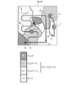
- FIG. 3 is a plan view showing an example of a traveling area of the utility vehicle according to the present embodiment.
- FIG. 4 is a flowchart for exemplifying the flow of travel control processing according to the road surface condition in the autonomous travel mode of the present embodiment.
- FIG. 1 is a schematic left side view showing a utility vehicle according to an embodiment.
- the utility vehicle 1 shown in FIG. 1 (hereinafter, simply referred to as a vehicle 1) includes a pair of left and right front wheels 2 and a pair of left and right rear wheels 3.
- the front wheels 2 and the rear wheels 3 support the vehicle body frame 4.
- the vehicle body frame 4 is a pipe frame formed by connecting a plurality of pipes to each other.
- the vehicle body frame 4 supports the front row seat 5A and the rear row seat 5B.
- the front row seat 5A includes the driver's seat.
- the seats are not limited to two rows and may be one row.
- the vehicle body frame 4 is configured to surround the occupant space C including the front row seat 5A and the rear row seat 5B. That is, the occupant space C is partitioned by the vehicle body frame 4.
- a bonnet 6 is arranged in front of the occupant space C (front row seat 5A).
- the bonnet 6 is supported by the front portion of the vehicle body frame 4 and covers the space between the left and right front wheels 2 so as to be openable and closable from above.
- a front row side door 7A is provided on the side of the front row seat 5A, and a rear row side door 7B is provided on the side of the rear row seat 5B.
- These side doors 7A and 7B are supported by the vehicle body frame 4.
- the side doors 7A and 7B open and close with respect to the vehicle body frame 4 by rotating around a rotation axis provided at the front end portion thereof. As a result, the occupant can get on and off the vehicle 1.
- the side doors 7A and 7B are shown so as to be transparent to the inside (passenger space C side).
- a loading platform 8 is arranged behind the occupant space C (rear row seat 5B).
- the rear portion of the vehicle body frame 4 supports the loading platform 8.
- a drive source 9 supported by the vehicle body frame 4 is arranged below the loading platform 8.
- the drive source 9 is, for example, an engine.
- the drive source 9 may be an electric motor or a combination of an engine and an electric motor.
- the drive source 9 drives the drive wheels (front wheels 2 and / or rear wheels 3).
- a first operator 10 including an accelerator pedal and a brake pedal is provided in front of and below the driver's seat (driver's foot area). By operating the accelerator pedal, the driving force of the driving source 9 changes. Brake devices (not shown) are provided on the front wheels 2 and the rear wheels 3, and the vehicle 1 is decelerated by operating the brake pedal. In this way, the first operator 10 is configured as an operator for accelerating and decelerating the vehicle 1.
- the front wheel 2 is provided with a steering device 11. Further, a steering wheel 12 is provided as a second operator in front of the driver's seat in the front row seat 5A.
- the steering wheel 12 is connected to the steering device 11, and the steering device 11 operates in response to an operation on the steering wheel 12 to steer the front wheels 2.
- the second operator is configured as an operator for changing the direction of the vehicle 1.
- the vehicle 1 is provided with a transmission (not shown) connected between the drive source 9 and the drive wheels.
- the transmission changes the gear ratio or changes the traveling direction (forward or backward) based on an operation on a third operator such as a shift lever (not shown).
- the traveling device 14 for traveling the vehicle 1 includes a front wheel 2, a rear wheel 3, a steering device 11, a drive source 9, a brake device, a transmission device, and the like. Further, the operators for operating the traveling device 14 include a first operator, a second operator, a third operator, and the like.
- the vehicle 1 is provided with a control device 13 for controlling the traveling device 14.
- Various sensors which will be described later, are connected to the control device 13.
- the control device 13 acquires the detected values of various sensors.
- the control device 13 has a processor, a volatile memory, a non-volatile memory (storage), an I / O interface, and the like, and the processor performs arithmetic processing using the volatile memory based on a program stored in the non-volatile memory. As a result, it is configured as an electronic circuit that realizes various controls.
- FIG. 2 is a block diagram showing an outline of the control system of the utility vehicle shown in FIG. As shown in FIG. 2, various sensors are connected to the control device 13. The sensor detects the vehicle state of the traveling system including the operator and the traveling device 14.
- the sensors include, for example, an accelerator opening sensor 15, a brake amount sensor 16, a steering angle sensor 17, a drive source rotation speed sensor 18, a vehicle speed sensor 19, a wheel rotation speed sensor 20, a suspension stroke sensor 21, a pitch angle sensor 22, and a roll angle. Includes sensor 23 and the like.
- the vehicle 1 may include all of these sensors, may include some of these sensors, or may include sensors other than these sensors.
- the accelerator opening sensor 15 detects the amount of operation of the accelerator pedal.
- the brake amount sensor 16 detects the operation amount of the brake pedal.
- the steering angle sensor 17 detects the operation direction and the operation amount of the steering wheel 12.
- the drive source rotation speed sensor 18 detects the rotation speed of the output shaft of the drive source 9.
- the vehicle speed sensor 19 detects the speed of the vehicle 1.
- the wheel rotation speed sensor 20 detects the rotation speed of each of the wheels 2 and 3.
- the wheel rotation speed sensor 20 may be provided on each of the four wheels (left and right front wheels 2 and left and right rear wheels 3). Instead of providing the vehicle speed sensor 19, the vehicle speed may be obtained from the rotation speed of the wheels of the drive wheels (for example, the rear wheel 3).
- the suspension stroke sensor 21 detects the amount of expansion and contraction of the suspension (not shown) provided for each of the wheels 2 and 3 of the vehicle 1.
- the suspension stroke sensor 21 may be provided on each of the four suspensions provided on each of the four wheels.
- the pitch angle sensor 22 detects the rotation angle of the vehicle 1 around the pitch axis (virtual rotation axis extending in the vehicle width direction) of the vehicle 1. Instead of providing the pitch angle sensor 22, the pitch angle may be detected from the difference in the amount of expansion and contraction between the front suspension and the rear suspension detected by the suspension stroke sensor 21.
- the roll angle sensor 23 detects the rotation angle of the vehicle 1 around the roll axis of the vehicle 1 (a virtual rotation axis extending in the front-rear direction of the vehicle). Instead of providing the roll angle sensor 23, the roll angle may be detected from the difference in the amount of expansion and contraction between the right suspension and the left suspension detected by the suspension stroke sensor 21.
- the control device 13 controls the traveling device 14 so that autonomous traveling that does not require manned operation can be performed in a predetermined traveling area.
- a mode switching unit 50 is connected to the control device 13.
- the mode switching unit 50 has a manned operation mode in which the operation according to the operation to the operator is performed, and an autonomous driving mode in which the control device 13 performs autonomous driving in accordance with a predetermined travel route without the operation to the operator. Switch.
- the mode switching unit 50 transmits a mode switching signal based on switching by a switch, various authentication operations, and the like to the control device 13.
- the control device 13 switches the control mode between the manned operation mode and the autonomous driving mode according to the received mode switching signal.
- the control device 13 controls the traveling device 14 in response to inputs to various controls operated by the driver. For example, the control device 13 adjusts the output of the drive source 9 (in the case of an engine, control of the throttle opening, etc.) based on the accelerator opening detected by the accelerator opening sensor 15 in response to the driver's operation on the accelerator pedal. )I do. Further, for example, the control device 13 adjusts the steering angle of the steering device 11 based on the steering angle and the steering direction detected by the steering angle sensor 17 in response to the driver's operation on the steering wheel 12.
- the control device 13 performs autonomous travel according to a predetermined travel route without requiring an operation on the operator.
- the vehicle 1 includes a front space detecting unit 29 for detecting the state of the vehicle (front traveling space of the vehicle 1) and a vehicle position detecting unit 30 for detecting the position of the vehicle.
- the front space detection unit 29 includes, for example, at least one such as a camera, various radars, and a laser sensor.
- the control device 13 analyzes the front space based on the image data of the front space captured by the camera and / or the distance data measured by various radars or laser sensors.
- the control device 13 controls the traveling device 14 based on the analysis result of the front space. For example, when there is an obstacle in front, the control device 13 controls the drive source 9 and / or the brake device (not shown) so as to decelerate or stop the vehicle 1, or to change the traveling direction of the vehicle 1.
- the steering device 11 is controlled.
- the own vehicle position detection unit 30 is provided with, for example, a GPS antenna or the like.
- the storage device of the control device 13 stores preset travel route data.
- the control device 13 reads out the data of the traveling route in the autonomous driving mode, and controls the traveling device 14 so as to travel along the traveling route based on the information of the own vehicle position from the own vehicle position detecting unit 30. Further, the control device 13 finely adjusts the traveling route based on the above-mentioned analysis result of the front space. For example, when there is an obstacle in front, the control device 13 sets the reroute of the traveling route.
- the vehicle 1 is provided with a route setting device 41 for setting a travel route for autonomous travel.
- the route setting device 41 may be configured as a control block of the control device 13, or may be configured by another computer.
- the route setting device 41 may be provided in the vehicle 1 or a mobile terminal (tablet terminal) capable of communicating via a communication network. ) Etc. may be configured by a computer.
- the route setting device 41 is configured to be able to communicate with the outside via a communication network, and is connected to a data receiving unit 42 that receives predetermined data from the outside.
- the travel route data is information set and input via a predetermined server device, for example, by a user setting and inputting a travel route to a mobile terminal (tablet terminal or the like) capable of communicating with the vehicle 1 via a communication network in advance. Is transmitted to the control device 13 of the vehicle 1.
- the vehicle 1 may be equipped with an operation terminal connected to the control device 13 for the user to set and input a travel route.
- the mode switching unit 50 has a manned operation mode in which the operation according to the operation to the operator is performed, and an autonomous driving mode in which the mode switching unit 50 performs autonomous driving in which the operation to the operator is not required according to a predetermined travel route. Is switched. Therefore, when performing periodic work or the like, by executing the autonomous driving mode, manned operation is unnecessary and the work load can be reduced. Further, it can be used as a manned operation utility vehicle 1 by executing a manned operation mode as needed, such as when performing temporary work. Therefore, according to the above configuration, it is possible to enable flexible operation in the utility vehicle 1 capable of autonomous driving according to a predetermined traveling route.
- the vehicle 1 can get on the occupant space C even in the autonomous traveling mode. That is, the vehicle 1 can travel either manned or unmanned in the autonomous traveling mode.
- the vehicle 1 is activated by the user performing a predetermined activation operation.
- the mode switching unit 50 transmits a mode switching signal for switching to the autonomous driving mode to the control device 13.
- the control device 13 causes the route setting device 41 to execute the travel route setting process (travel route setting program).
- the travel route may be set by reading it out. If the travel route is not stored in the storage device, or if the travel route is different from the previous one, the travel route may be reset. In this case, for example, the route may be set by a mobile terminal capable of wirelessly or wiredly communicating with the vehicle 1.
- the route setting device 41 executes a travel route setting program, and sets a travel route from input information such as waypoints and destinations, information on the position of the own vehicle, and terrain information stored in advance corresponding to a map. do. Further, for example, when the vehicle 1 is used for patrol security in a predetermined area, a travel route in which the route setting device 41 travels over the entire patrol area by setting and inputting the patrol area on a map. May be configurable. After setting the travel path, the control device 13 starts autonomous travel.
- the control device 13 controls the traveling device 14 according to the road surface condition in front of the traveling direction of the own vehicle position during autonomous traveling in the autonomous traveling mode. For this purpose, the control device 13 acquires road surface condition data in the traveling region.
- the road surface condition data divides the traveling area into a plurality of predetermined road surface condition levels.
- the road surface condition data is stored in a storage device (server device, mobile terminal, etc.) outside the vehicle 1 capable of communicating through a storage device in the vehicle 1 or a communication network.
- FIG. 3 is a plan view showing an example of a traveling area of the utility vehicle according to the present embodiment.
- FIG. 4 is a flowchart for exemplifying the flow of travel control processing according to the road surface condition in the autonomous travel mode of the present embodiment.
- the vehicle 1 is used to perform a predetermined work in the work area WA (for example, a material collection site).
- the vehicle 1 performs, for example, material transportation work or work area WA monitoring work (patrol travel) in the work area WA.
- the work area WA is preset as the travel area SA of the vehicle 1.
- the path of reciprocating movement between the first position P1 and the second position P2 in the work area WA (the first path R1 from the first position P1 to the second position P2 and the first position P1 from the second position P2).
- the second route R2) to to can be set as a travel route during autonomous travel.
- the first position P1 is set to the outside carry-out place of the material
- the second position P2 is set to the material storage place.
- the vehicle 1 in the autonomous traveling mode moves from the first position P1 to the second position P2 and stops.
- the material is loaded onto the loading platform 8 of the vehicle 1.
- the vehicle 1 moves from the second position P2 to the first position P1 and stops.
- materials are loaded and unloaded.
- the vehicle 1 in the autonomous traveling mode repeatedly reciprocates between the first position P1 and the second position P2.
- the traveling route during autonomous traveling is a traveling route in which the monitoring work is performed by patrolling the work area WA on a predetermined traveling route starting from the third position P3 of the working area WA.
- the third travel path R3 includes, for example, a meandering section M that reciprocates in the first direction X of the work area WA and moves in the second direction Y at the time of turning.
- the work area WA set as the traveling area SA has a plurality of predetermined road surface condition levels (Lv1, Lv2-1, Lv2-2, Lv3) (4 in the example of FIG. 3). It is divided into.
- the road surface condition data includes data indicating the road surface condition level at each position of the traveling area SA.
- the control device 13 reads out the travel route and road surface condition data set from the route setting device 41 (step S1). For example, the reading of the road surface condition data is performed by sequentially reading out the data portion indicating the road surface condition in the region ahead of the traveling direction of the own vehicle position traveling route.
- the control device 13 determines which of the plurality of road surface condition levels the road surface condition in front of the own vehicle position of the vehicle 1 belongs to from the road surface condition data during autonomous driving (step S2).
- the control device 13 acquires the vehicle position and the traveling direction (direction) of the vehicle 1 from the vehicle position detecting unit 30, and obtains the road surface condition level in the traveling direction front region of the vehicle position in the traveling region SA from the road surface condition data. Inquire.
- the road surface condition level is divided into stages according to the inclination angle ⁇ of the vehicle 1 when the vehicle 1 is traveling.
- the tilt angle of the vehicle may be set as either a pitch angle or a roll angle. Further, the tilt angle of the vehicle may be a three-dimensional angle considering both the pitch angle and the roll angle.
- the first level Lv1 is set in a region where the inclination angle ⁇ is less than the first angle ⁇ 1 when the vehicle 1 travels.
- Second level Lv2 when the vehicle 1 has traveled, the inclination angle theta is set to the first angle theta 1 or more and the first angle theta 1 is greater than the second angle theta region as less than 2.
- the third level Lv3 is set in a region where the inclination angle ⁇ is equal to or greater than the second angle ⁇ 2 when the vehicle 1 travels.
- the second level Lv2 is further divided into a first sub-level Lv2-1 and a second sub-level Lv2-2.
- the first sub-level Lv2-1 seems to have an inclination angle ⁇ of 1 or more and less than a sub-angle ⁇ S larger than the first angle ⁇ 1 and smaller than the second angle ⁇ 2 when the vehicle 1 travels. Area is set.
- the second sub-level Lv2-2 is set in a region where the inclination angle ⁇ is equal to or greater than the sub-angle ⁇ S and less than the second angle ⁇ 2 when the vehicle 1 travels.
- the control device 13 controls the travel device 14 so that the predetermined travel parameters are within the preset allowable range corresponding to each of the plurality of road surface condition levels (steps S3 to S7). More specifically, the control device 13 determines whether or not the road surface condition level is the first level Lv1 (step S3). When the control device 13 determines that the road surface condition level is the first level Lv1 (Yes in step S3), the control device 13 performs normal control (without limitation) (step S4).
- the control device 13 determines whether or not the road surface condition level is the second level Lv2 (step S5).
- the control device 13 determines that the road surface condition level is the second level Lv2 (Yes in step S5), the control device 13 performs traveling restriction control (step S6).
- the control device 13 controls to avoid approaching (step S7).
- the following example shows a case where the traveling parameters include speed and steering angle.
- the control device 13 controls the traveling device 14 without speed limitation and steering angle limitation based on the road surface condition level when the road surface condition level is the first level Lv1.
- normal traveling control is performed in the road surface condition where the posture of the vehicle 1 is stable.
- it is permissible to limit the speed other than the road surface condition level such as when the vehicle 1 is cornering or when traveling in a predetermined speed limit region or the like.
- the control device 13 controls the traveling device 14 so that the speed of the vehicle 1 becomes equal to or less than the first reference speed V1 when the road surface condition level is the second level Lv2. Further, the control device 13 controls the traveling device 14 so that the range of the steering angle becomes equal to or less than the predetermined reference range ⁇ in addition to the above speed limit when the road surface condition level is the second sub-level Lv2-2. do. The control device 13 does not limit the steering angle when the road surface condition level is the first sub-level Lv2-1 or the first level Lv1.
- the speed is limited in the road surface condition where the vehicle 1 passes through an obstacle (rocky place, depression, etc.) that can be run, or passes on a slope above a certain level.
- the vehicle 1 can be overturned by steering at a large steering angle when the vehicle 1 is tilted when passing through an obstacle or the like. The sex can be reduced.
- the different restriction controls may be an increase / decrease in the type (number) of the restricted driving parameters, an increase / decrease in the allowable range in the same driving parameters, or a combination thereof.
- the control device 13 controls the traveling device 14 so as to avoid the entry of the vehicle 1 into the region when the road surface condition level is the third level Lv3. For example, when the vehicle 1 in FIG. 3 is located at the position Pa, the control device 13 determines the road surface condition level in the region Aa ahead of the vehicle 1 in the traveling direction. Since the road surface condition level of the region Aa is the third level Lv3, the control device 13 does not enter the region Aa but steers. The route setting device 41 resets the traveling route accordingly.
- the traveling device 14 when the vehicle 1 is autonomously traveling, the traveling device 14 is controlled differently according to the road surface condition level ahead of the traveling direction of the own vehicle position. Therefore, in a place where the road surface condition is bad, the traveling control in autonomous driving such as traveling at a low speed can be changed from the control in the place where the road surface condition is good. Therefore, in the vehicle 1 capable of traveling on rough terrain, it is possible to appropriately control autonomous traveling according to the road surface condition.
- the allowable range of driving parameters can be set not only at the upper limit but also at the lower limit.
- the control device 13 sets an upper limit value of the speed and a lower limit value of the speed (minimum speed in steady driving) when the road surface condition level is the second level Lv2 for which the traveling restriction control should be performed. You may. As a result, it is possible to perform appropriate traveling control even on a road surface where the vehicle 1 may be stuck when traveling at a low speed. That is, the possibility that the vehicle 1 is stuck can be reduced.
- the driving parameters to be controlled are not limited to the above example.
- the traveling parameters may include acceleration, gear ratio, suspension damping force, vehicle height, and the like, in addition to the above speed and steering angle.
- the control device 13 controls the traveling device 14 so that the acceleration becomes equal to or less than a predetermined reference acceleration when the road surface condition level is the second level Lv2 for which the traveling restriction control should be performed. This makes it possible to prevent slipping due to sudden acceleration on a slippery road surface.
- the vehicle 1 is provided with a transmission (having a plurality of stages) capable of selectively switching a plurality of gear ratios (ratio of the rotation speed of the output shaft of the drive source 9 to the rotation speed of the output shaft of the transmission).
- the control device 13 is a traveling device so that the road surface condition level is equal to or lower than the reference gear ratio (reference stage or higher) among the plurality of gear ratios when the road surface condition level is the second level Lv2 for which the traveling restriction control should be performed. 14 is controlled. This makes it possible to prevent slipping due to an increase in output torque on a slippery road surface.
- the control device 13 determines that the road surface condition level is the second level Lv2 for which the traveling restriction control should be performed.
- the traveling device 14 is controlled so that the damping force of the suspension is low.
- the control device 13 is a traveling device so that the vehicle height becomes high when the road surface condition level is the second level Lv2 for which the traveling restriction control should be performed. 14 is controlled.
- the control device 13 can acquire predetermined data regarding the vehicle loading status or the external environment of the vehicle 1 from the data receiving unit 42, and can correct the permissible range associated with the road surface condition level based on the acquired data. For example, the vehicle 1 detects the weight of the load on the loading platform 8 and / or the number of seats on the seats 5A and 5B. The detected weight of the cargo and / or the number of seated persons is sent to the control device 13 via the data receiving unit 42.
- the control device 13 is, for example, in the traveling restriction control when the road surface condition level is the second level Lv2 when the weight of the load is equal to or more than the predetermined reference weight and / or when the number of seated persons is equal to or more than the predetermined reference number. Change the permissible range of driving parameters to be controlled narrower. For example, in the above example, when the road surface condition level is the first sub-level Lv2-1, the control device 13 changes the permissible speed range to the second reference speed V2 or less, which is lower than the first reference speed V1.
- the control device 13 raises the road surface condition level by one level (a level at which the limit becomes stricter by one level). ) May be changed. That is, in the above example, when the road surface condition level is the first sub-level Lv2-1, the control device 13 performs the traveling limitation control of the second sub-level Lv2-2, that is, the speed limitation and the steering angle limitation. You may go. Further, when the road surface condition level is the second sub-level Lv2-2, the control device 13 may perform control of the third level Lv3, that is, control for avoiding the entry of the vehicle 1 into the area.
- the vehicle 1 includes, for example, weather, temperature, atmospheric pressure, season, date and time, region (climate zone), ground type (muddy area, wet area, sandy beach, desert, etc.) as data on the external environment of the vehicle 1. obtain.
- One of these data may be used, or a plurality of them may be used in combination.
- Data related to the external environment (for example, weather, season, date and time, area, etc.) are stored in, for example, a server device that is communicated and connected to the data receiving unit 42 of the vehicle 1 via a communication network, and is stored in the data receiving unit 42 from the server device.
- Sent Alternatively, the data related to the external environment (for example, temperature, atmospheric pressure, road surface condition, etc.) may be, for example, a value detected by a sensor provided in the vehicle 1.
- the control device 13 has an allowable range of traveling parameters to be controlled in the traveling restriction control when the road surface condition level is the second level Lv2 when the weather is rainy or the atmospheric pressure is equal to or lower than a predetermined reference atmospheric pressure. May be changed to a narrower level, or the road surface condition level may be changed to a higher level. Further, for example, when the control device 13 is traveling on a muddy ground or the like where stacking is likely to occur, or when the air temperature is below a predetermined reference temperature (for example, below the freezing point), the control device 13 sets the minimum speed during steady traveling to a third. The reference speed may be set to V3 or higher.
- the vehicle 1 includes a road surface condition estimation device 43 that creates road surface condition data.
- the road surface condition estimation device 43 may be configured as a functional block of the control device 13, or may be configured as a calculation device different from the control device 13.
- the road surface condition estimation device 43 estimates the road surface condition at the position of the own vehicle from a predetermined driving index, and determines which of the plurality of road surface condition levels set in advance from the estimation result, and thereby obtains the road surface condition data. create.
- the travel index is at least one index indicating the travel state of the vehicle 1, and is acquired by the travel index acquirer 44.
- the traveling index is a pitch angle and / or a roll angle indicating the posture of the vehicle 1. Therefore, the travel index acquirer 44 includes the pitch angle sensor 22 and / or the roll angle sensor 23. In addition to or instead of this, the travel index acquirer 44 may include various other sensors 15 to 21 depending on the travel index to be acquired.
- FIG. 2 illustrates that the travel index acquirer 44 includes various sensors 15 to 23 and a digital model forming unit 45 described later, but a sensor or the like for obtaining a desired travel index is the travel index acquirer 44. The other sensor does not have to function as the travel index acquirer 44.
- the travel index may include a first travel index indicating the posture of the vehicle 1.
- the travel index may include a second travel index indicating the force exerted on the front wheels 2 and / or the rear wheels 3 (hereinafter, the force on the wheels).
- the first running index indicating the posture of the vehicle 1 can be obtained by directly measuring the pitch angle and / or the roll angle as described above. Further, the travel index acquirer 44 may be one or more of the accelerator opening, the brake amount, the steering angle, the rotation speed of the output shaft of the drive source 9, the vehicle speed, the wheel rotation speed, the stroke amount of the suspension, and the like at that time. The first running index may be corrected by using the index.
- the second running index indicating the force on the wheels of the vehicle 1 includes, for example, the slip ratio of each wheel.
- the slip ratio is obtained by measuring the vehicle speed and the wheel rotation speed, obtaining the deviation of the wheel rotation speed with respect to the vehicle speed, and dividing the deviation by the vehicle speed.
- the traveling index acquirer 44 may use one or more of the accelerator opening, the brake amount, the steering angle, the rotation speed of the output shaft of the drive source 9, the suspension stroke amount, the pitch angle, the roll angle, and the like at that time.
- the second running index may be corrected by using the index.
- the travel index acquirer 44 may include a digital model forming unit 45 that forms a digital model of the vehicle 1.
- the travel index acquirer 44 detects at least one vehicle state value indicating the state of the vehicle 1.
- the digital model forming unit 45 forms a digital model regarding the running state of the vehicle 1 from at least one vehicle state value.
- the travel index acquirer 44 extracts a travel index from the digital model.
- the digital model forming unit 45 may form a digital model of the vehicle 1 by using the state values related to the posture of the vehicle 1 such as the pitch angle and the roll angle as the vehicle state values.
- the travel index acquirer 44 may extract the grip force on each of the wheels 2 and 3 of the formed digital model as a travel index.
- the travel index acquirer 44 may correct the travel index based on the detection result by the front space detection unit 29 when acquiring the travel index. For example, when the front space detection unit 29 is a camera, the travel index acquirer 44 analyzes the image in front of the vehicle 1 captured by the front space detection unit 29 to estimate the friction coefficient of the travel road surface. The travel index acquirer 44 uses the obtained friction coefficient to correct the travel index measured or obtained from the digital model. Further, for example, the travel index acquirer 44 may analyze the image in front of the vehicle 1 captured by the front space detection unit 29 to estimate the posture of the vehicle 1 and correct the travel index based on the estimation.
- the road surface condition estimation device 43 estimates the road surface condition in the travel route traveled in the manned operation mode, and creates the road surface condition data by associating the travel route with the road surface condition level.
- the travel index acquirer 44 acquires the travel index at the position of the own vehicle while traveling in the manned travel mode.
- the road surface condition estimation device 43 estimates the road surface condition from the traveling index at the own vehicle position, and determines which of the plurality of road surface condition levels the road surface condition at the own vehicle position belongs to.
- the control device 13 stores the road surface condition level of the own vehicle position obtained by the determination in association with the data of the own vehicle position.
- the control device 13 may overwrite the new data as the data at that position, or average the accumulated data and the new data. You may update by performing the processing of.
- the traveling area SA an area that has not traveled in the past is set as a non-traveling area.
- the storage location of the road surface condition data may be a storage device inside the vehicle 1 or a storage device (server device, mobile terminal, etc.) outside the vehicle 1 capable of communicating through the communication network.
- the road surface condition estimation device 43 maps the road surface condition level in the predetermined traveling area SA by storing the road surface condition level in the traveling route traveled in the manned operation mode in association with the own vehicle position.
- the mapped data is stored as road surface condition data (road surface condition map).
- the road surface condition estimation device 43 may apply the adjacent road surface condition data by analogy to the road surface condition of the region portion that is not traveling in the manned operation mode in the traveling region SA, or may apply the adjacent road surface condition data by analogy, or may apply the adjacent road surface condition data to the non-traveling region (third level Lv3). ) May be used.
- the road surface condition estimation device 43 may estimate the road surface condition in the traveling route when the vehicle 1 autonomously travels using the road surface condition data created in the manned operation mode, and may update the road surface condition data.
- the vehicle 1 is driven in the autonomous driving mode without performing the driving control in consideration of the road surface condition, so that the road surface condition estimation device 43 acquires the driving index and obtains the driving index.
- the road surface condition may be estimated based on the estimation.
- the control device 13 drives the traveling device 14 so that the vehicle 1 autonomously travels according to a predetermined traveling pattern or a traveling route set by the user.
- the road surface condition estimation device 43 estimates the road surface condition at that time, and creates road surface condition data by associating the traveling route with the road surface condition level. For example, if the vehicle 1 falls, the posture of the vehicle 1 (roll angle, pitch angle, etc.) exceeds the standard range, or the vehicle 1 becomes unable to travel due to a stack or the like.
- the road surface condition level at the position is set to the third level Lv3.
- the road surface condition estimation device 43 may estimate the road surface condition in the traveling route when traveling in the autonomous traveling mode using the road surface condition data, and may update the road surface condition data.
- the road surface condition data may be created by performing a running simulation of a virtual vehicle imitating the vehicle 1.
- the driving simulation may be performed by the road surface condition estimation device 43, a computer outside the vehicle 1 capable of communicating with the vehicle 1 through the communication network, or an independent computer that does not communicate with the vehicle 1.
- the road surface condition data obtained as a result may be transferred to the storage device of the vehicle 1 or the like via a recording medium or the like.
- topographical data in the running area SA is prepared. Topographical data is created from, for example, satellite images.
- the computer that performs the running simulation creates a virtual running space based on the road surface shape data in the running area SA. Further, the computer generates a virtual vehicle imitating the vehicle 1 and arranges it in the virtual traveling space.
- the computer performs a driving simulation to drive a virtual vehicle in the generated virtual driving space.
- the traveling state of the virtual vehicle changes according to the terrain change in the virtual traveling space.
- the attitude of the virtual vehicle or the force on the wheels at this time is acquired as a running index, and the road surface condition is estimated.
- the computer creates road surface condition data (road surface condition map) by dividing the virtual traveling space into a plurality of road surface condition levels based on the estimation result of the road surface condition.
- Machine learning can be used in such driving simulations.
- machine learning that classifies into multiple road surface condition levels by supervised learning may be performed.
- different road surface condition levels may be assigned to the road surface condition classifications classified into a plurality of categories by unsupervised learning, and the allowable range of the corresponding driving parameters may be determined.
- the road surface condition data in the virtual traveling space obtained in such a traveling simulation is used as the road surface condition data in the actual traveling area SA. Further, the road surface condition estimation device 43 may estimate the actual road surface condition in the traveling route when traveling in the autonomous traveling mode using the road surface condition data, and may update the road surface condition data.
- the road surface condition level included in the road surface condition data may be set to one dimension based on one viewpoint (posture of the vehicle 1) as in the example shown in FIG. 3, but is two-dimensional by combining a plurality of viewpoints. Or it may be set to more multidimensional.
- road surface condition data having a two-dimensional road surface condition level by combining a one-dimensional type 1 road surface condition level based on the vehicle attitude and a one-dimensional type 2 road surface condition level based on the estimated friction coefficient of the road surface in a matrix. May be generated.
- the control device 13 may limit sudden acceleration. , It is possible to perform control such as limiting the maximum speed at the time of steering. Further, in such a case, it may be muddy or on the water (crossing the river), so that the control device 13 travels at a preset minimum speed or higher in order to prevent the vehicle 1 from getting stuck. You may control it.
- the road surface condition is estimated when the vehicle 1 is running, and data on the external environment at that time (for example, weather, temperature, atmospheric pressure, season, date and time, area, ground type, etc. as described above) are acquired.
- the road surface condition level at that position may be set to a different level according to the index of the external environment.
- the road surface condition level in fine weather is the first sub-level Lv2-1
- the road surface condition level in rainy weather is the second sub-level Lv2-2, and so on. Multiple settings may be made depending on the situation.
- control device 13 may determine the road surface condition level for each of the left and right wheels 2 and 3 as the road surface condition in front of the vehicle 1 in the traveling direction. In this case, for example, the control device 13 detects the roll angle, and when the roll angle is equal to or greater than the reference value, determines that the vehicle 1 is in a state of crossing and advancing with respect to the inclination. When the control device 13 determines that the vehicle 1 is in a state of crossing the inclination and traveling, and the road surface condition level is the second level Lv2 for which the traveling limit control (speed limit) should be performed, the speed limit is applied. In addition, if the steering angle range is limited and it is determined that the vehicle 1 is not in a state of crossing the slope and the road surface condition level is the second level Lv2, the speed is limited but the steering angle is limited. The range may not be limited.
- control device 13 may determine the road surface condition level for each of the four front, rear, left, and right wheels as the road surface condition in front of the vehicle 1 in the traveling direction.
- the road surface condition level (second level Lv2) for which the traveling restriction control is performed includes two sub-levels Lv2-1 and Lv2-2 having different allowable ranges of traveling parameters or types of traveling parameters.
- the road surface condition level (second level Lv2) for performing the travel restriction control may correspond to one control content or may include three or more sub-levels.
- Multiple road surface conditions that can vary the permissible range of driving parameters or the types of driving parameters (possible to perform driving restriction control) include, for example, wet paved roads, gravel roads, farmlands, grasslands, steep slopes, rivers, rocky areas, etc. Includes snow, muddy, sandy beaches, deserts, etc.
- the road surface condition data created in each of the above modes may be used for setting a traveling route. That is, the route setting device 41 may set a traveling route based on the road surface condition data. For example, when a plurality of travel routes can be set when moving the vehicle 1 from the current position to a desired destination, the route setting device 41 sets the road surface condition level to a predetermined level (for example, a second sub-level) in which the vehicle 1 can travel. A travel route with a shorter distance on the travel route that is Lv2-2) or higher is adopted.
- the route setting device 41 sets a travel route that more satisfies the priority condition. For example, when the travel route is set with priority given to distance when the vehicle 1 is moved to a desired destination, the route setting device 41 is at a level where the road surface condition level is somewhat high (for example, the second sub-level Lv2-2) or higher. Allow the adoption of a certain route. Further, for example, when the traveling route is set by giving priority to time when moving the vehicle 1 to a desired destination, the route setting device 41 takes into consideration the speed limit according to the road surface condition level and the arrival time is shorter. Adopt a travel route.
- the route setting device 41 determines that the road surface condition level can be traveled.
- a travel route having a shorter distance on the travel route that is equal to or higher than the level of (for example, the second sub-level Lv2-2) is adopted.
- the route setting device 41 may further set the traveling route so that the state where the road surface condition levels of the left and right road surfaces where the left and right wheels 2 and 3 touch each other is less likely to be different.
- the route group on which the vehicle 1 or the virtual vehicle traveled (does not become inoperable) at the time of creating the road surface condition data by actual traveling or machine learning may be registered as a traveling route candidate.
- the route setting device 41 selects the optimum route from the route group based on the setting data of the travel route such as the destination, or combines a plurality of routes included in the route group and sets it as the travel route. You may.
- the number of changes in the travel route during autonomous travel can be reduced, and efficient travel of the vehicle 1 can be realized.
- the front space detection unit 29 is configured to be able to detect a monitoring target such as a person or an animal by analyzing a captured image, and the front space detection unit 29 detects a monitoring target during autonomous driving or manned operation.
- the control device 13 stores the position of the own vehicle at that time in a storage device or the like as encounter history data.
- the user who gets on the vehicle 1 can perform a predetermined operation input to register the position of the own vehicle at the time of the operation input as a place where the monitoring target is detected.
- the route setting device 41 may change a part or all of the traveling route based on the encounter history data.
- the route setting device 41 may set a traveling route so as to avoid a place where the monitoring target is frequently encountered. This can reduce the risk of contact with humans or animals. Further, it is possible to reduce the possibility that the vehicle 1 is attacked or the cargo is plundered when traveling in a conflict area or an insecure area, for example, for transporting goods.
- the route setting device 41 may set a travel route that preferentially passes through a location where the monitoring target is frequently encountered. Thereby, for example, when traveling for patrol security (monitoring) in the traveling area SA by the vehicle 1 in a vast agricultural land or a forest, it is possible to set a traveling route with high discovery efficiency.
- the front space detection unit 29 is configured to be able to detect light emission by analyzing an captured image during nighttime driving, and the front space detection unit 29 is configured to be capable of detecting light emission during nighttime autonomous driving or manned operation.
- the control device 13 stores the position of the own vehicle at that time in a storage device or the like as light emission history data.
- the user who gets on the vehicle 1 can perform a predetermined operation input to register the position of the own vehicle at the time of the operation input as a place where light emission is detected.
- the route setting device 41 may change a part or all of the traveling route based on the light emission history data.
- the vehicle 1 may include a first control device (first ECU) that controls the vehicle 1 in the manned operation mode and a second control device (second ECU) that controls the vehicle 1 in the autonomous driving mode.
- first ECU first ECU
- second ECU second ECU
- the vehicle 1 capable of traveling by manned operation is exemplified, but the control in the autonomous traveling mode of the above-described embodiment may be applied to the vehicle 1 dedicated to autonomous driving.
- the vehicle 1 provided with the road surface condition estimation device 43 is exemplified, but the road surface condition estimation device 43 may not be provided. That is, the control device 13 acquires the road surface condition data from the storage unit of the vehicle 1 or an external storage device, determines which of the plurality of road surface condition levels the road surface condition in front of the vehicle position in the traveling direction belongs to. Other configurations may be omitted as long as the travel device 14 is configured to control the travel device 14 so that the predetermined travel parameters are within the preset tolerances corresponding to each of the plurality of road surface condition levels. ..
- the road surface condition data in the above embodiment may be common data for a plurality of vehicle types. However, when the traveling ability differs depending on the vehicle type, the allowable range of the traveling parameter corresponding to one road surface condition level or the type of the traveling parameter may differ depending on the vehicle type.
- the speed is limited at the first sub-level Lv2-1, and the running limit and the steering range are limited at the second sub-level Lv2-2.
- the running is controlled to do.
- the speed is limited to a lower speed or less at the first sub-level Lv2-1 and the steering range is limited, and the second sub-level Lv2-2 is restricted. Then, the control for avoiding the entry of the vehicle 1 into the area may be performed.
- the running levels divided into a plurality of levels based on the running ability of the vehicle 1 may be stored in a storage device or the like as data to be read when the control device 13 performs running control.
- the control device 13 may determine the travel control content corresponding to the road surface condition level and the travel level by reading the travel level of the vehicle 1 after determining the road surface condition level.
Abstract
ユーティリティビークルは、前輪および後輪と、前輪に設けられた操舵装置と、前輪および/または後輪を駆動する駆動源と、を含む走行装置と、所定の走行領域において有人操作を要しない自律走行を行うように、走行装置を制御する制御装置と、自車位置を検知する自車位置検知部と、を備え、制御装置は、自律走行時において、走行領域を予め定められた複数の路面状況レベルに区分した路面状況データから、自車位置の進行方向前方における路面状況が複数の路面状況レベルの何れに属するかを判定し、所定の走行パラメータが複数の路面状況レベルのそれぞれに対応して予め設定された許容範囲内となるように、走行装置を制御する。
Description
本開示は、ユーティリティビークルに関する。
不整地等を走行可能なユーティリティビークルは、例えば、農作物等の運搬作業や、敷地内の監視作業等に利用される。このような作業は、予め定められた走行経路を走行し、定期的に繰り返し行われることが想定される。
また、近年、自動車において自律運転を行うための種々の技術が提案されている。例えば、下記特許文献1には、予め定められた走行経路を自律運転車両が走行するシステムが開示されている。これによれば、予め定められた走行経路の走行において有人操作を不要とすることができる。
このような従来の自律運転車両では、不整地での走行が想定されていない。例えば、従来の自律運転車両では、前方に障害物があると判定された場合にはそれを回避するか車両を停止させる制御を行う。しかし、不整地を走行するユーティリティビークルは、多少の障害物は乗り越えて走行可能である。そのため、不整地を走行するユーティリティビークルにおける自律運転には、従来の平地を移動する自律運転車両とは異なる制御が必要となる。
そこで、本開示は、不整地を走行可能なユーティリティビークルにおいて、適切な自律走行の制御を行うことができるユーティリティビークルを提供することを目的とする。
本開示の一態様に係るユーティリティビークルは、前輪および後輪と、前記前輪に設けられた操舵装置と、前記前輪および/または前記後輪を駆動する駆動源と、を含む走行装置と、所定の走行領域において有人操作を要しない自律走行を行うように、前記走行装置を制御する制御装置と、自車位置を検知する自車位置検知部と、を備え、前記制御装置は、前記自律走行時において、前記走行領域を予め定められた複数の路面状況レベルに区分した路面状況データから、前記自車位置の進行方向前方における路面状況が前記複数の路面状況レベルの何れに属するかを判定し、所定の走行パラメータが前記複数の路面状況レベルのそれぞれに対応して予め設定された許容範囲内となるように、前記走行装置を制御する。
本開示によれば、ユーティリティビークルの自律走行時に、自車位置の進行方向前方における路面状況レベルに応じて異なる走行装置の制御が行われる。このため、路面状況の悪い場所では、例えば低速走行する等、自律走行における走行制御を路面状況の良い場所での制御とは変えることができる。したがって、不整地を走行可能なユーティリティビークルにおいて、路面状況に応じた適切な自律走行の制御を行うことができる。
以下、図面を参照しながら実施形態について説明する。全図を通じて、同一のまたは対応する要素には同一の符号を付して重複説明を省略する。
(車両の構成)
図1は、一実施の形態におけるユーティリティビークルを示す概略左側面図である。図1に示すユーティリティビークル1(以下、単に車両1と称する)は、左右一対の前輪2と左右一対の後輪3とを備える。前輪2および後輪3は、車体フレーム4を支持している。車体フレーム4は、複数のパイプを互いに接続してなるパイプフレームである。
図1は、一実施の形態におけるユーティリティビークルを示す概略左側面図である。図1に示すユーティリティビークル1(以下、単に車両1と称する)は、左右一対の前輪2と左右一対の後輪3とを備える。前輪2および後輪3は、車体フレーム4を支持している。車体フレーム4は、複数のパイプを互いに接続してなるパイプフレームである。
車体フレーム4は、前列シート5Aおよび後列シート5Bを支持している。前列シート5Aは、運転席を含む。なお、座席は2列に限られず1列でもよい。車体フレーム4は、前列シート5Aおよび後列シート5Bを含む乗員空間Cを取り囲むように構成されている。すなわち、乗員空間Cは、車体フレーム4によって区画される。乗員空間C(前列シート5A)の前方には、ボンネット6が配置されている。ボンネット6は、車体フレーム4の前部に支持され、左右の前輪2の間のスペースを上方から開閉可能に覆っている。
前列シート5Aの側方には、前列サイドドア7Aが設けられ、後列シート5Bの側方には、後列サイドドア7Bが設けられる。これらのサイドドア7A,7Bは、車体フレーム4に支持されている。各サイドドア7A,7Bは、車体フレーム4に対して、それぞれ前端部に設けられた回動軸回りに回動することにより、開閉する。これにより、乗員の車両1への乗り降りが可能となる。なお、図1においてサイドドア7A,7Bは、その内側(乗員空間C側)が透過するように示されている。
乗員空間C(後列シート5B)の後方には、荷台8が配置されている。車体フレーム4の後部は、荷台8を支持している。荷台8の下方には、車体フレーム4に支持された駆動源9が配置されている。駆動源9は例えばエンジンである。これに代えて、駆動源9は電気モータまたはエンジンと電気モータとの組み合わせであってもよい。駆動源9は、駆動輪(前輪2および/または後輪3)を駆動する。
運転席の前方かつ下方(運転者の足元領域)には、アクセルペダルおよびブレーキペダルを含む第1操作子10が設けられる。アクセルペダルを操作することにより駆動源9の駆動力が変化する。前輪2および後輪3には、図示しないブレーキ装置が設けられ、ブレーキペダルを操作することにより車両1が減速する。このように、第1操作子10は、車両1を加減速させるための操作子として構成される。
前輪2には操舵装置11が設けられる。また、前列シート5Aのうちの運転席の前方には、第2操作子としてハンドル12が設けられる。ハンドル12は、操舵装置11に接続されており、ハンドル12への操作に応じて操舵装置11が動作し、前輪2を操舵する。このように、第2操作子は、車両1を方向転換させるための操作子として構成される。
さらに、車両1には、駆動源9と駆動輪との間に接続される変速装置(図示せず)を備えている。変速装置は、図示しない変速レバー等の第3操作子への操作に基づいて変速比を変化させたり、走行方向(前進または後退)を変化させたりする。
以上のように、車両1を走行させるための走行装置14は、前輪2、後輪3、操舵装置11、駆動源9、ブレーキ装置、および変速装置等を含む。また、走行装置14を操作するための操作子は、第1操作子、第2操作子、および第3操作子等を含む。
さらに、車両1は、走行装置14を制御するための制御装置13を備えている。制御装置13には、後述する各種センサが接続される。制御装置13は、各種センサの検出値を取得する。制御装置13は、プロセッサ、揮発性メモリ、不揮発性メモリ(記憶器)およびI/Oインターフェース等を有し、不揮発性メモリに保存されたプログラムに基づいてプロセッサが揮発性メモリを用いて演算処理することで各種制御を実現する電子回路として構成される。
(制御系の構成)
図2は、図1に示すユーティリティビークルの制御系の概略を示すブロック図である。図2に示すように、制御装置13には、各種センサが接続される。センサは、操作子および走行装置14を含む走行系の車両状態の検知を行う。
図2は、図1に示すユーティリティビークルの制御系の概略を示すブロック図である。図2に示すように、制御装置13には、各種センサが接続される。センサは、操作子および走行装置14を含む走行系の車両状態の検知を行う。
センサは、例えば、アクセル開度センサ15、ブレーキ量センサ16、操舵角センサ17、駆動源回転数センサ18、車速センサ19、車輪回転数センサ20、サスストロークセンサ21、ピッチ角センサ22、ロール角センサ23等を含む。車両1は、これらのセンサのすべてを備えていてもよいし、これらのセンサのうちの一部を備えていてもよいし、これらのセンサ以外のセンサを備えていてもよい。
アクセル開度センサ15は、アクセルペダルの操作量を検知する。ブレーキ量センサ16は、ブレーキペダルの操作量を検知する。操舵角センサ17は、ハンドル12の操作方向および操作量を検知する。駆動源回転数センサ18は、駆動源9の出力軸の回転数を検知する。車速センサ19は、車両1の速度を検知する。
車輪回転数センサ20は、各車輪2,3の回転数を検知する。車輪回転数センサ20は、4つの車輪(左右の前輪2および左右の後輪3)のそれぞれに設けられ得る。なお、車速センサ19を設ける代わりに、駆動輪の車輪(例えば後輪3)の回転数から車速が求められてもよい。サスストロークセンサ21は、車両1の車輪2,3ごとに設けられるサスペンション(図示せず)の伸縮量を検知する。サスストロークセンサ21は、4つの車輪のそれぞれに設けられた4つのサスペンションのそれぞれに設けられ得る。
ピッチ角センサ22は、車両1のピッチ軸(車両幅方向に延びる仮想の回転軸)回りの車両1の回転角を検知する。なお、ピッチ角センサ22を設ける代わりに、サスストロークセンサ21が検知する前側サスペンションと後側サスペンションとの間の伸縮量の差からピッチ角が検知されてもよい。ロール角センサ23は、車両1のロール軸(車両前後方向に延びる仮想の回転軸)回りの車両1の回転角を検知する。なお、ロール角センサ23を設ける代わりに、サスストロークセンサ21が検知する右側サスペンションと左側サスペンションとの間の伸縮量の差からロール角が検知されてもよい。
制御装置13は、所定の走行領域において有人操作を要しない自律走行を行い得るように、走行装置14を制御する。制御装置13には、モード切替部50が接続される。モード切替部50は、操作子への操作に応じた走行を行う有人操作モードと、制御装置13により、所定の走行経路に従って操作子への操作を必要としない自律走行を行う自律走行モードとを切り替える。
モード切替部50は、スイッチによる切り替えや、各種認証操作等に基づいたモード切替信号を制御装置13に送信する。制御装置13は、受信したモード切替信号に応じて制御モードを有人操作モードと自律走行モードとの間で切り替える。
有人操作モードにおいて、制御装置13は、運転者が操作する各種操作子への入力に応じて走行装置14の制御を行う。例えば、制御装置13は、運転者のアクセルペダルへの操作に応じてアクセル開度センサ15が検知するアクセル開度に基づいて、駆動源9の出力調整(エンジンの場合はスロットル開度の制御等)を行う。また、例えば、制御装置13は、運転者のハンドル12への操作に応じて操舵角センサ17が検知する操舵角および操舵方向に基づいて、操舵装置11の舵角調整を行う。
一方、自律走行モードにおいて、制御装置13は、所定の走行経路に従って操作子への操作を必要としない自律走行を行う。例えば、車両1は、車両1の前方走行空間)の状態を検知するための前方空間検知部29および自車位置を検知するための自車位置検知部30を備えている。
前方空間検知部29は、例えば、カメラ、各種レーダ、およびレーザセンサ等の少なくとも1つを備えている。制御装置13は、カメラで撮像した前方空間の画像データ、および/または、各種レーダまたはレーザセンサで測距した距離データ等に基づいて、前方空間の解析を行う。制御装置13は、前方空間の解析結果に基づいて走行装置14を制御する。例えば、前方に障害物がある場合、制御装置13は、車両1を減速または停車させるように駆動源9および/またはブレーキ装置(図示せず)を制御したり、車両1の進行方向を変えるために操舵装置11を制御したりする。
自車位置検知部30は、例えばGPSアンテナ等を備えている。制御装置13の記憶器には、予め設定された走行経路のデータが記憶される。制御装置13は、自律走行モードにおいて走行経路のデータを読み出し、自車位置検知部30からの自車位置の情報に基づいて走行経路に沿って走行するように走行装置14を制御する。さらに、制御装置13は、上記した前方空間の解析結果に基づいて走行経路を微調整する。例えば、前方に障害物がある場合、制御装置13は、走行経路のリルート設定を行う。
車両1は、自律走行の走行経路を設定する経路設定装置41を備えている。経路設定装置41は、制御装置13の制御ブロックとして構成されてもよいし、別のコンピュータにより構成されてもよい。経路設定装置41が制御装置13とは異なる別のコンピュータにより構成される場合、経路設定装置41は、車両1内に設けられてもよいし、通信ネットワークを介して通信可能な携帯端末(タブレット端末)等のコンピュータにより構成されてもよい。
経路設定装置41は、通信ネットワークを介して外部と通信可能に構成され、外部から所定のデータを受信するデータ受信部42が接続されている。走行経路のデータは、例えば予め車両1と通信ネットワークを介して通信可能な携帯端末(タブレット端末等)にユーザが走行経路を設定入力することにより、所定のサーバ装置を介して設定入力された情報が車両1の制御装置13に送信される。あるいは、制御装置13に接続され、ユーザが走行経路を設定入力するための操作端末が車両1に搭載されてもよい。
上記構成によれば、モード切替部50により、操作子への操作に応じた走行を行う有人操作モードと、所定の走行経路に従って操作子への操作を必要としない自律走行を行う自律走行モードとが切り替えられる。したがって、定期的な作業等を行う場合には自律走行モードを実行することにより、有人操作を不要とし、作業負担を軽減することができる。また、臨時的な作業を行う場合等、必要に応じて有人操作モードを実行することにより、有人操作のユーティリティビークル1として使用することができる。したがって、上記構成によれば、所定の走行経路に従った自律走行が可能なユーティリティビークル1において、柔軟な運用を可能とすることができる。
なお、本実施の形態において、車両1は、自律走行モードにおいても乗員空間Cへの乗車が可能である。すなわち、車両1は、自律走行モードにおいて有人または無人のいずれでも走行可能である。
(自律走行モードの詳細)
以下、自律走行モードについてより詳しく説明する。例えば、ユーザが所定の起動操作を行うことにより、車両1が起動する。ユーザが自律走行モードへのモード切替操作を行うことにより、モード切替部50は、制御装置13に自律走行モードに切り替えるためのモード切替信号を送信する。その後、制御装置13は、経路設定装置41に走行経路の設定処理(走行経路設定プログラム)を実行させる。
以下、自律走行モードについてより詳しく説明する。例えば、ユーザが所定の起動操作を行うことにより、車両1が起動する。ユーザが自律走行モードへのモード切替操作を行うことにより、モード切替部50は、制御装置13に自律走行モードに切り替えるためのモード切替信号を送信する。その後、制御装置13は、経路設定装置41に走行経路の設定処理(走行経路設定プログラム)を実行させる。
走行経路の設定は、記憶器に走行経路が予め記憶されている場合にはそれを読み出すことで行われてもよい。記憶器に走行経路が記憶されていない場合、または、前回とは異なる走行経路で走行させる場合には、走行経路の再設定を行い得る。この場合、例えば、車両1と無線または有線で通信接続可能な携帯端末で経路設定を行ってもよい。
例えば、携帯端末に地図を表示し、地図上で経由地または目的地等を設定入力する。経路設定装置41は、走行経路設定プログラムを実行し、入力された経由地および目的地等の情報、自車位置の情報、および地図に対応して予め記憶された地形情報等から走行経路を設定する。また、例えば、車両1を所定の領域内を巡回警備するために用いる場合には、巡回領域を地図上で設定入力することにより、経路設定装置41が巡回領域の全域を走行するような走行経路を設定可能としてもよい。走行経路の設定後、制御装置13は、自律走行を開始する。
(路面状況に応じた走行制御)
制御装置13は、自律走行モードによる自律走行時において、自車位置の進行方向前方における路面状況に応じた走行装置14の制御を行う。このために、制御装置13は、走行領域における路面状況データを取得する。路面状況データは、走行領域を予め定められた複数の路面状況レベルに区分したものである。路面状況データは、車両1内の記憶器または通信ネットワークを通じて通信可能な車両1外の記憶装置(サーバ装置または携帯端末等)に記憶されている。
制御装置13は、自律走行モードによる自律走行時において、自車位置の進行方向前方における路面状況に応じた走行装置14の制御を行う。このために、制御装置13は、走行領域における路面状況データを取得する。路面状況データは、走行領域を予め定められた複数の路面状況レベルに区分したものである。路面状況データは、車両1内の記憶器または通信ネットワークを通じて通信可能な車両1外の記憶装置(サーバ装置または携帯端末等)に記憶されている。
図3は、本実施の形態におけるユーティリティビークルの走行領域の例を示す平面図である。また、図4は、本実施の形態の自律走行モードにおける路面状況に応じた走行制御の処理の流れを例示するためのフローチャートである。図3の例において、車両1は、作業領域WA(例えば資材集積場等)で所定の作業を行うために用いられる。車両1は、作業領域WA内において、例えば、資材の搬送作業または作業領域WAの監視作業(巡回走行)等を行う。図3の例において、作業領域WAが車両1の走行領域SAとして予め設定される。
例えば、作業領域WA内の第1位置P1と第2位置P2との間の往復移動の経路(第1位置P1から第2位置P2への第1経路R1および第2位置P2から第1位置P1への第2経路R2)が自律走行時の走行経路として設定され得る。例えば、第1位置P1は、資材の外部への搬出場に設定され、第2位置P2は、資材置場に設定される。
この場合、自律走行モードの車両1は、第1位置P1から第2位置P2に移動し、停車する。第2位置P2では、資材が車両1の荷台8に積み込まれる。資材の積み込み後、車両1は、第2位置P2から第1位置P1に移動し、停車する。第1位置P1では、資材が積み下ろされる。このような作業を行うために、自律走行モードの車両1は、第1位置P1と第2位置P2との間を繰り返し往復移動する。
また、例えば、作業領域WAの第3位置P3を起点として、作業領域WA内を所定の走行経路で巡回して監視作業を行う巡回走行の経路が自律走行時の走行経路(第3走行経路R3)として設定され得る。第3走行経路R3は、例えば、作業領域WAの第1方向Xに往復動しつつ方向転換時に第2方向Yへ移動する蛇行区間Mを含む。
図3に示すように、走行領域SAとして設定される作業領域WAは、予め定められた複数(図3の例では4つ)の路面状況レベル(Lv1,Lv2-1,Lv2-2,Lv3)に区分されている。路面状況データは、走行領域SAの各位置における路面状況レベルを示すデータを含んでいる。
制御装置13は、制御モードが自律走行モードに切り替えられた場合、経路設定装置41から設定された走行経路および路面状況データを読み出す(ステップS1)。例えば、路面状況データの読み出しは、自車位置走行経路の進行方向前方の領域の路面状況を示すデータ部分を逐次読み出すことで行われる。
制御装置13は、自律走行時において、路面状況データから、車両1の自車位置の進行方向前方における路面状況が複数の路面状況レベルの何れに属するかを判定する(ステップS2)。制御装置13は、自車位置検知部30から自車位置と車両1の進行方向(方角)とを取得し、路面状況データから走行領域SAにおける自車位置の進行方向前方領域の路面状況レベルを照会する。
例えば、路面状況レベルは、車両1の走行時に車両1の傾斜角θに応じて段階分けされる。車両の傾斜角は、ピッチ角またはロール角の何れか一方として設定されてもよい。また、車両の傾斜角は、ピッチ角およびロール角の双方を考慮した三次元的な角度としてもよい。第1レベルLv1は、車両1が走行したときに、傾斜角θが第1角度θ1未満であるような領域に設定される。第2レベルLv2は、車両1が走行したときに、傾斜角θが第1角度θ1以上かつ第1角度θ1より大きい第2角度θ2未満であるような領域に設定される。第3レベルLv3は、車両1が走行したときに、傾斜角θが第2角度θ2以上であるような領域に設定される。
第2レベルLv2は、さらに、第1サブレベルLv2-1および第2サブレベルLv2-2に段階分けされる。第1サブレベルLv2-1は、車両1が走行したときに、傾斜角θが第1角度θ1以上かつ第1角度θ1より大きく第2角度θ2より小さいサブ角度θS未満であるような領域に設定される。第2サブレベルLv2-2は、車両1が走行したときに、傾斜角θがサブ角度θS以上かつ第2角度θ2未満であるような領域に設定される。
制御装置13は、所定の走行パラメータが複数の路面状況レベルのそれぞれに対応して予め設定された許容範囲内となるように、走行装置14を制御する(ステップS3~S7)。より具体的には、制御装置13は、路面状況レベルが第1レベルLv1であるか否かを判定する(ステップS3)。制御装置13は、路面状況レベルが第1レベルLv1であると判定したときに(ステップS3でYes)、通常の(制限を行わない)制御を行う(ステップS4)。
制御装置13は、路面状況レベルが第2レベルLv2ではないと判定したときに(ステップS3でNo)、路面状況レベルが第2レベルLv2であるか否かを判定する(ステップS5)。制御装置13は、路面状況レベルが第2レベルLv2であると判定したときに(ステップS5でYes)、走行制限制御を行う(ステップS6)。制御装置13は、路面状況レベルが第2レベルLv2ではなく、路面状況レベルが第3レベルLv3であると判定したときに(ステップS5でNo)、進入を回避する制御を行う(ステップS7)。
例えば、以下の例では、走行パラメータに速度および操舵角を含む場合を示す。この場合、制御装置13は、路面状況レベルが第1レベルLv1であるときに、路面状況レベルに基づく速度制限および操舵角制限を行わずに走行装置14を制御する。これにより、車両1の姿勢が安定する路面状況においては、通常の走行制御が行われる。なお、この場合でも、車両1がコーナリング中の場合、予め定められた速度制限領域等を走行する場合等、路面状況レベル以外の速度制限を行うことは許容される。
制御装置13は、路面状況レベルが第2レベルLv2であるときに、車両1の速度が第1基準速度V1以下になるように走行装置14を制御する。さらに、制御装置13は、路面状況レベルが第2サブレベルLv2-2であるときに、上記速度制限に加えて、操舵角の範囲を所定の基準範囲θ以下になるように走行装置14を制御する。なお、制御装置13は、路面状況レベルが第1サブレベルLv2-1または第1レベルLv1であるときには操舵角の制限は行わない。
これにより、車両1が走破可能な障害物(岩場または窪地等)を通過したり、ある程度以上の斜面を通行したりするような路面状況においては、速度制限が行われる。さらに、障害物または斜面の程度によって操舵角範囲の制限が行われることにより、障害物の通過時等の車両1が傾斜している状態において大舵角で転舵することによる車両1の転倒可能性を低減することができる。
このように、路面状況レベルが走行制限制御を行うべき第2レベルLv2であるときに、第2レベルLv2に属する複数のサブレベルLv2-1,Lv2-2に応じて異なる走行制限制御が行われる。異なる制限制御は、上記のように、制限される走行パラメータの種類(数)の増減でもよいし、同じ走行パラメータにおける許容範囲の増減でもよいし、それらの組み合わせでもよい。
制御装置13は、路面状況レベルが第3レベルLv3であるときに、当該領域への車両1の進入を回避するように走行装置14を制御する。例えば、図3の車両1が位置Paに位置しているとき、制御装置13は、車両1の進行方向前方の領域Aaにおける路面状況レベルの判断を行う。領域Aaの路面状況レベルは、第3レベルLv3であるため、制御装置13は、その領域Aaへの進入は行わず、転舵を行う。経路設定装置41は、これに応じて走行経路の再設定を行う。
上記構成によれば、車両1の自律走行時に、自車位置の進行方向前方における路面状況レベルに応じて異なる走行装置14の制御が行われる。このため、路面状況の悪い場所では、例えば低速走行する等、自律走行における走行制御を路面状況の良い場所での制御とは変えることができる。したがって、不整地を走行可能な車両1において、路面状況に応じた適切な自律走行の制御を行うことができる。
なお、走行パラメータの許容範囲は、上限だけでなく下限も設定され得る。例えば、制御装置13は、路面状況レベルが走行制限制御を行うべき第2レベルLv2であるときに、速度の上限値を設定するとともに、速度の下限値(定常走行時における最低速度)を設定してもよい。これにより、低速で走行すると車両1がスタックする可能性のある路面に対しても適切な走行制御を行うことができる。すなわち、車両1がスタックする可能性を低減することができる。
また、制御対象の走行パラメータは、上記例に限られない。例えば、走行パラメータは、上記速度および操舵角以外に、加速度、変速比、サスペンションの減衰力、車高等を含み得る。例えば、制御装置13は、路面状況レベルが走行制限制御を行うべき第2レベルLv2であるときに、加速度が所定の基準加速度以下になるように走行装置14を制御する。これにより、滑り易い路面において急加速によるスリップが発生すること等を防止することができる。
また、例えば、車両1が複数の変速比(変速装置の出力軸の回転数に対する駆動源9の出力軸の回転数の比率)を選択的に切り替え可能な(複数段を有する)変速装置を備えている場合、制御装置13は、路面状況レベルが走行制限制御を行うべき第2レベルLv2であるときに、複数の変速比のうちの基準変速比以下(基準段以上)になるように走行装置14を制御する。これにより、滑り易い路面において出力トルクの増大によるスリップが発生すること等を防止することができる。
また、例えば、車両1がサスペンションの油圧制御または電子制御等による減衰力調整機構を備えている場合、制御装置13は、路面状況レベルが走行制限制御を行うべき第2レベルLv2であるときに、サスペンションの減衰力が低くなるように走行装置14を制御する。また、例えば、車両1が車高調整機構を備えている場合、制御装置13は、路面状況レベルが走行制限制御を行うべき第2レベルLv2であるときに、車高が高くなるように走行装置14を制御する。
制御装置13は、データ受信部42から車両積載状況または車両1の外部環境に関する所定のデータを取得し、取得したデータに基づいて、路面状況レベルに対応付けられた許容範囲を補正可能である。例えば、車両1は、荷台8への積荷の重量および/または各座席5A,5Bへの着座人数を検知する。検知した積荷の重量および/または着座人数は、データ受信部42を介して制御装置13に送られる。
制御装置13は、例えば、積荷の重量が所定の基準重量以上である場合および/または着座人数が所定の基準人数以上である場合、路面状況レベルが第2レベルLv2であるときの走行制限制御における制御対象である走行パラメータの許容範囲をより狭く変更する。例えば、上記例において、制御装置13は、路面状況レベルが第1サブレベルLv2-1のとき、速度の許容範囲を、第1基準速度V1より低い第2基準速度V2以下に変更する。
あるいは、制御装置13は、積荷の重量が所定の基準重量以上である場合および/または着座人数が所定の基準人数以上である場合、路面状況レベルを1段階高いレベル(制限が一段階厳しくなるレベル)に変更してもよい。すなわち、上記例において、制御装置13は、路面状況レベルが第1サブレベルLv2-1のとき、第2サブレベルLv2-2の走行制限制御、すなわち、速度制限を行うとともに、操舵角の制限を行ってもよい。また、制御装置13は、路面状況レベルが第2サブレベルLv2-2のとき、第3レベルLv3の制御、すなわち、当該領域への車両1の進入を回避する制御を行ってもよい。
また、車両1は、車両1の外部環境に関するデータとして、例えば天候、気温、気圧、季節、日時、地域(気候帯)、地面の種別(泥濘地、湿地帯、砂浜、砂漠等)等を含み得る。これらのデータのうちの1つを用いてもよいし、複数を組み合わせて用いてもよい。外部環境に関するデータ(例えば天候、季節、日時、地域等)は、例えば、車両1のデータ受信部42と通信ネットワークを介して通信接続されるサーバ装置に蓄積され、サーバ装置からデータ受信部42に送られる。あるいは、外部環境に関するデータ(例えば気温、気圧、路面の状態等)は、例えば、車両1に設けられたセンサで検知された値でもよい。
例えば、制御装置13は、天候が雨である場合または気圧が所定の基準気圧以下である場合、路面状況レベルが第2レベルLv2であるときの走行制限制御における制御対象である走行パラメータの許容範囲をより狭く変更する、または、路面状況レベルをより高いレベルに変更してもよい。また、例えば、制御装置13は、泥濘地等のスタックしやすい地面上を走行中である場合または気温が所定の基準温度以下(例えば氷点下以下)である場合、定常走行時における最低速度を第3基準速度V3以上に設定してもよい。
このように、車両1の重量変化や外部環境の変化に応じて路面状況レベルに応じた走行パラメータの許容範囲を変更することにより、より実情に沿った走行制御を行うことができる。
(路面状況の推定)
車両1は、路面状況データを作成する路面状況推定装置43を備えている。路面状況推定装置43は、制御装置13の機能ブロックとして構成されてもよいし、制御装置13とは別の演算装置として構成されてもよい。
車両1は、路面状況データを作成する路面状況推定装置43を備えている。路面状況推定装置43は、制御装置13の機能ブロックとして構成されてもよいし、制御装置13とは別の演算装置として構成されてもよい。
路面状況推定装置43は、所定の走行指標から自車位置における路面状況を推定し、その推定結果から予め設定される複数の路面状況レベルの何れに属するかを判定することにより、路面状況データを作成する。走行指標は、車両1の走行状態を示す少なくとも1つの指標であり、走行指標取得器44により取得される。
例えば、上記例において、走行指標は、車両1の姿勢を示すピッチ角および/またはロール角である。したがって、走行指標取得器44は、ピッチ角センサ22および/またはロール角センサ23を含む。なお、これに加えてまたはこれに代えて、走行指標取得器44は、取得すべき走行指標に応じてその他の各種センサ15~21を含んでもよい。図2には、走行指標取得器44が各種センサ15~23および後述するデジタルモデル形成部45を含むように例示されているが、所望の走行指標を得るためのセンサ等が走行指標取得器44として機能すれば他のセンサは走行指標取得器44として機能しなくてもよい。
例えば、走行指標は、車両1の姿勢を示す第1走行指標を含んでもよい。これに加えてまたはこれに代えて、走行指標は、前輪2および/または後輪3にかかる力(以下、車輪への力)を示す第2走行指標を含んでもよい。
車両1の姿勢を示す第1走行指標は、上記のようにピッチ角および/またはロール角を直接計測することで取得することができる。さらに、走行指標取得器44は、そのときのアクセル開度、ブレーキ量、操舵角、駆動源9の出力軸の回転数、車速、車輪回転数、サスペンションのストローク量等の中から一または複数の指標を用いて第1走行指標を補正してもよい。
また、車両1の車輪への力を示す第2走行指標は、例えば各車輪のスリップ率を含む。スリップ率は、車速および車輪回転数を計測し、車速に対する車輪回転数の偏差を求め、偏差を車速で割ることで得られる。さらに、走行指標取得器44は、そのときのアクセル開度、ブレーキ量、操舵角、駆動源9の出力軸の回転数、サスペンションのストローク量、ピッチ角、ロール角等の中から一または複数の指標を用いて第2走行指標を補正してもよい。
また、走行指標の取得は、各種センサが計測した値から直接的に取得することに限られない。例えば、走行指標取得器44は、車両1のデジタルモデルを形成するデジタルモデル形成部45を備えていてもよい。この場合、走行指標取得器44は、車両1の状態を示す少なくとも1つの車両状態値を検知する。デジタルモデル形成部45は、少なくとも1つの車両状態値から車両1の走行状態に関するデジタルモデルを形成する。走行指標取得器44は、デジタルモデルから走行指標を抽出する。例えば、デジタルモデル形成部45は、車両状態値としてピッチ角、ロール角等の車両1の姿勢に関する状態値を用いて車両1のデジタルモデルを形成してもよい。走行指標取得器44は、形成されたデジタルモデルの各車輪2,3におけるグリップ力を走行指標として抽出してもよい。
さらに、走行指標取得器44は、走行指標の取得の際に、前方空間検知部29による検知結果に基づいて走行指標を補正してもよい。例えば、前方空間検知部29がカメラである場合、走行指標取得器44は、前方空間検知部29により撮像された車両1の前方の画像を解析して走行路面の摩擦係数を推定する。走行指標取得器44は、得られた摩擦係数を用いて計測またはデジタルモデルから得られた走行指標を補正する。また、例えば、走行指標取得器44は、前方空間検知部29により撮像された車両1の前方の画像を解析して車両1の姿勢を推定し、それに基づいて走行指標を補正してもよい。
路面状況推定装置43は、有人操作モードで走行した走行経路における路面状況を推定し、走行経路と路面状況レベルとを対応付けることにより、路面状況データを作成する。この場合、走行指標取得器44は、有人走行モードによる走行中、自車位置における走行指標を取得する。路面状況推定装置43は、自車位置における走行指標から路面状況を推定し、自車位置の路面状況が複数の路面状況レベルの何れに属するかを判定する。
制御装置13は、判定によって得られた自車位置の路面状況レベルを自車位置のデータに対応付けて記憶する。同じ位置における路面状況レベルのデータが既に蓄積されている場合には、制御装置13は、新しいデータをその位置のデータとして上書きしてもよいし、蓄積されているデータと新しいデータとについて平均等の処理を行って更新してもよい。また、走行領域SAにおいて過去に走行していない領域は、走行不能領域に設定される。路面状況データの記憶箇所は、車両1内の記憶器でもよいし、通信ネットワークを通じて通信可能な車両1外の記憶装置(サーバ装置または携帯端末等)でもよい。
このように、路面状況推定装置43は、有人操作モードで走行した走行経路における路面状況レベルを自車位置と対応付けて記憶することにより、所定の走行領域SAにおける路面状況レベルのマッピングを行う。マッピングされたデータが路面状況データ(路面状況マップ)として記憶される。
このように、有人操作による走行時に路面状況データを作成することにより、安全にかつ実際の路面状況に即した路面状況データを作成することができる。
なお、路面状況推定装置43は、走行領域SAにおいて有人操作モードで走行していない領域部分の路面状況について、隣接する路面状況データを類推適用してもよいし、走行不能領域(第3レベルLv3)としてもよい。
さらに、路面状況推定装置43は、上記有人操作モードで作成された路面状況データを用いて車両1が自律走行したときの走行経路における路面状況を推定し、路面状況データを更新してもよい。
有人走行モードを用いた路面状況レベルのマッピングの代わりに、車両1を路面状況を考慮した走行制御を行わずに自律走行モードで走行させることにより、路面状況推定装置43が、走行指標の取得およびそれに基づく路面状況の推定を行ってもよい。
例えば、制御装置13は、予め定められた走行パターンまたはユーザが設定した走行経路に従って車両1が自律走行するように走行装置14を走行させる。路面状況推定装置43は、そのときの路面状況を推定し、走行経路と路面状況レベルとを対応付けることにより、路面状況データを作成する。例えば、仮に車両1が転倒した場合、車両1の姿勢(ロール角、ピッチ角等)が基準の範囲を超えた場合、または、車両1がスタック等により走行不能になった場合等には、その位置における路面状況レベルは第3レベルLv3に設定される。
このように、車両1を自律走行させて路面状況データを作成することにより、人手を掛けずに実際の路面状況に即した路面状況データを作成することができる。なお、路面状況推定装置43は、上記路面状況データを用いた自律走行モードで走行したときの走行経路における路面状況を推定し、路面状況データを更新してもよい。
あるいは、路面状況データは、車両1を模した仮想の車両の走行シミュレーションを行うことにより作成されてもよい。走行シミュレーションは、路面状況推定装置43が行ってもよいし、車両1と通信ネットワークを通じて通信可能な車両1外のコンピュータが行ってもよいし、車両1とは通信を行わない独立したコンピュータが行い、その結果として得られた路面状況データが車両1の記憶器等に記録媒体等を介してデータ移送されてもよい。
走行シミュレーションに際して、走行領域SAにおける地形データが用意される。地形データは、例えば衛星画像等から作成される。走行シミュレーションを行うコンピュータは、走行領域SAにおける路面形状データに基づいて仮想の走行空間を生成する。また、コンピュータは、車両1を模した仮想の車両を生成し、仮想の走行空間に配置する。
コンピュータは、生成された仮想の走行空間において仮想の車両を走行させる走行シミュレーションを行う。仮想の車両は、仮想の走行空間における地形変化に応じて走行状態が変化する。このときの仮想の車両の姿勢または車輪への力等を走行指標として取得し、路面状況を推定する。コンピュータは、路面状況の推定結果に基づいて仮想の走行空間を複数の路面状況レベルに区分けすることにより、路面状況データ(路面状況マップ)を作成する。このような走行シミュレーションにおいては、機械学習が利用され得る。
例えば教師あり学習により複数の路面状況レベルに分類するような機械学習が行われてもよい。あるいは、教師なし学習により複数に分類された路面状況の区分について互いに異なる路面状況レベルを割り当て、対応する走行パラメータの許容範囲が定められてもよい。
このような走行シミュレーションにおいて得られた仮想の走行空間における路面状況データが実際の走行領域SAにおける路面状況データとして用いられる。さらに、路面状況推定装置43は、上記路面状況データを用いた自律走行モードで走行したときの走行経路における実際の路面状況を推定し、路面状況データを更新してもよい。
このように、走行シミュレーションにより路面状況データを作成することにより、安全かつ走行領域SAの全域において漏れのない路面状況データを作成することができる。
路面状況データに含まれる路面状況レベルは、図3に示す例のように、1つの観点(車両1の姿勢)に基づいて一次元に設定されてもよいが、複数の観点の組み合わせにより二次元またはそれより多い多次元に設定されてもよい。例えば、車両姿勢に基づく一次元の第1種路面状況レベルと路面の推定摩擦係数に基づく一次元の第2種路面状況レベルとをマトリクス的に組み合わせて二次元の路面状況レベルを有する路面状況データが生成されてもよい。
例えば、第1種路面状況レベルが低い路面(平坦または傾斜の緩い路面)でも第2種路面状況レベルが高い路面(滑りやすい路面)の場合には、制御装置13は、急加速を制限したり、転舵時の最高速度を制限したりする制御を行い得る。また、このような場合には、ぬかるみまたは水上(渡河)である可能性もあるので、制御装置13は、車両1がスタックするのを防止すべく予め設定された最低速度以上で走行するように制御してもよい。
また、車両1の走行時に路面状況を推定するともに、そのときの外部環境に関するデータ(例えば、上述したような、天候、気温、気圧、季節、日時、地域、地面の種別等)を取得し、その位置における路面状況レベルを外部環境の指標に応じて異なるレベルに設定可能としてもよい。例えば、晴天時における路面状況レベルは第1サブレベルLv2-1であり、雨天時における路面状況レベルは第2サブレベルLv2-2である等のように一の位置における路面状況レベルをその他の条件に応じて複数設定してもよい。
また、制御装置13は、車両1の進行方向前方における路面状況として、左右の車輪2,3ごとに路面状況レベルの判定を行ってもよい。この場合、例えば、制御装置13は、ロール角を検知し、ロール角が基準値以上である場合に、車両1が傾斜に対して交差して進む状態にあると判定する。制御装置13は、車両1が傾斜に対して交差して進む状態にあると判定した場合、かつ路面状況レベルが走行制限制御(速度制限)を行うべき第2レベルLv2である場合、速度制限に加えて舵角範囲の制限を行い、車両1が傾斜に対して交差して進む状態にはないと判定した場合、かつ路面状況レベルが第2レベルLv2である場合、速度制限を行うが舵角範囲の制限は行わないとしてもよい。
同様に、制御装置13は、車両1の進行方向前方における路面状況として、前後左右4つの車輪ごとに路面状況レベルの判定を行ってもよい。
また、図3の例では、走行制限制御を行う路面状況レベル(第2レベルLv2)が、走行パラメータの許容範囲または走行パラメータの種類が異なる2つのサブレベルLv2-1,Lv2-2を含む例を示しているが、これに限られない。すなわち、走行制限制御を行う路面状況レベル(第2レベルLv2)は、1つの制御内容に対応してもよいし、3つ以上のサブレベルを含んでもよい。
走行パラメータの許容範囲または走行パラメータの種類を異ならせ得る(走行制限制御を行い得る)複数の路面状況は、例えば、濡れた舗装路、砂利道、農地、草地、急坂、川の中、岩場、雪面、ぬかるみ、砂浜、砂漠等を含む。
上記各態様で作成された路面状況データは、走行経路の設定に利用されてもよい。すなわち、経路設定装置41は、路面状況データに基づいて走行経路を設定してもよい。例えば、現在位置から所望の目的地まで車両1を移動させる場合に複数の走行経路が設定可能である場合、経路設定装置41は、路面状況レベルが走行可能な所定のレベル(例えば第2サブレベルLv2-2)以上となる走行経路上の距離がより短い走行経路を採用する。
あるいは、経路設定装置41は、走行経路の設定に際してユーザが優先条件を設定可能な場合、その優先条件をより満足するような走行経路を設定する。例えば、所望の目的地まで車両1を移動させる際に、距離優先で走行経路を設定する場合、経路設定装置41は、路面状況レベルがある程度高いレベル(例えば第2サブレベルLv2-2)以上である経路の採用を許容する。また、例えば、所望の目的地まで車両1を移動させる際に、時間優先で走行経路を設定する場合、経路設定装置41は、路面状況レベルに応じた制限速度を考慮して到達時間がより短い走行経路を採用する。
また、例えば、所望の目的地まで車両1を移動させる際に、車両1の姿勢変動の少なさを優先して走行経路を設定する場合、経路設定装置41は、路面状況レベルが走行可能な所定のレベル(例えば第2サブレベルLv2-2)以上となる走行経路上の距離がより短い走行経路を採用する。この場合、さらに、経路設定装置41は、左右の車輪2,3がそれぞれ接地する左右の路面の路面状況レベルが異なるような状態がより少なくなるような走行経路の設定を行ってもよい。
また、実走行または機械学習による路面状況データ作成時に車両1または仮想の車両が走行した(走行不能にならなかった)経路群が、走行経路候補として登録されていてもよい。経路設定装置41は、経路群の中から目的地等の走行経路の設定データに基づいて最適な経路を選択する、または、経路群に含まれる複数の経路を組み合わせて、それを走行経路として設定してもよい。
路面状況データに応じた走行経路が設定されることにより、自律走行時における走行経路の変更回数を少なくすることができ、車両1の効率的な走行を実現することができる。
なお、路面状況以外のデータが走行経路を設定するための他の条件として含まれていてもよい。例えば、前方空間検知部29が、撮像画像を解析すること等により人や動物等の監視対象を検知可能に構成され、自律走行時または有人操作による走行時に、前方空間検知部29が監視対象を発見した場合に、制御装置13は、そのときの自車位置を遭遇履歴データとして記憶器等に記憶する。有人操作による走行時においては、車両1に乗車したユーザが所定の操作入力を行うことにより、操作入力時の自車位置を監視対象を検知した箇所として登録し得る。経路設定装置41は、遭遇履歴データに基づいて走行経路の一部または全部を変更してもよい。
例えば、経路設定装置41は、監視対象に遭遇した頻度の高い箇所を避けるような走行経路を設定してもよい。これにより、人または動物との接触の危険性を下げることができる。また、例えば物資の搬送等のために紛争地域または治安のよくない地域において走行する際に、車両1が襲われたり、積荷を略奪されたりする可能性を下げることができる。
あるいは、経路設定装置41は、監視対象に遭遇した頻度の高い箇所を優先的に通るような走行経路を設定してもよい。これにより、例えば広大な農地または山林等において車両1による走行領域SAにおける巡回警備(監視)のための走行をさせる際に、発見効率の高い走行経路を設定することができる。
また、例えば、前方空間検知部29が、夜間の走行時における撮像画像を解析すること等により発光を検知可能に構成され、夜間の自律走行時または有人操作による走行時に、前方空間検知部29が発光(民家、サーチライト、火花等)を検知した場合に、制御装置13は、そのときの自車位置を発光履歴データとして記憶器等に記憶する。有人操作による走行時においては、車両1に乗車したユーザが所定の操作入力を行うことにより、操作入力時の自車位置を、発光を検知した箇所として登録し得る。経路設定装置41は、発光履歴データに基づいて走行経路の一部または全部を変更してもよい。
(他の実施の形態)
以上、本発明の実施の形態について説明したが、本発明は上記実施の形態に限定されるものではなく、その趣旨を逸脱しない範囲内で種々の改良、変更、修正が可能である。
以上、本発明の実施の形態について説明したが、本発明は上記実施の形態に限定されるものではなく、その趣旨を逸脱しない範囲内で種々の改良、変更、修正が可能である。
例えば、上記実施の形態では、共通の制御装置13が有人操作モードにおける制御および自律走行モードにおける制御の何れをも行う態様を例示したが、これに限られない。例えば、車両1は、有人操作モードにおける車両1の制御を行う第1制御装置(第1ECU)と自律走行モードにおける車両1の制御を行う第2制御装置(第2ECU)とを備えてもよい。
また、上記実施の形態では、有人操作による走行が可能な車両1を例示したが、自律走行専用の車両1において、上記実施の形態の自律走行モードにおける制御を適用してもよい。
また、上記実施の形態では、路面状況推定装置43を備えた車両1を例示したが、路面状況推定装置43は、備えていなくてもよい。すなわち、制御装置13が、路面状況データを車両1の記憶部または外部の記憶装置から取得し、自車位置の進行方向前方における路面状況が複数の路面状況レベルの何れに属するかを判定し、所定の走行パラメータが複数の路面状況レベルのそれぞれに対応して予め設定された許容範囲内となるように、走行装置14を制御するように構成されていれば、その他の構成はなくてもよい。
上記実施の形態における路面状況データは、複数の車種で共通のデータとしてもよい。ただし、車種によって走行能力が異なる場合には、一の路面状況レベルに対応する走行パラメータの許容範囲または走行パラメータの種類が車種ごとに異なってもよい。
例えば、悪路走破性の高い第1車両の場合に、上記例のように、第1サブレベルLv2-1で速度制限を行い、第2サブレベルLv2-2で走行制限および操舵範囲の制限を行うように走行制御される。一方、第1車両より悪路走破性の低い第2車両の場合には、第1サブレベルLv2-1でより低い速度以下に制限するとともに操舵範囲の制限を行い、第2サブレベルLv2-2ではその領域への車両1の進入を回避する制御を行ってもよい。
このために、車両1の走破能力に基づいて複数レベルに区分された走破レベルが、制御装置13が走行制御を行う際に読み出すデータとして記憶器等に記憶されてもよい。制御装置13は、路面状況レベルの判定後、その車両1の走破レベルを読み出すことで、路面状況レベルおよび走破レベルに対応する走行制御内容を決定してもよい。
1 ユーティリティビークル(車両)
2 前輪
3 後輪
9 駆動源
10,12 操作子
11 操舵装置
13 制御装置
14 走行装置
30 自車位置検知部
41 経路設定装置
43 路面状況推定装置
44 走行指標取得器
50 モード切替部
2 前輪
3 後輪
9 駆動源
10,12 操作子
11 操舵装置
13 制御装置
14 走行装置
30 自車位置検知部
41 経路設定装置
43 路面状況推定装置
44 走行指標取得器
50 モード切替部
Claims (10)
- 前輪および後輪と、前記前輪に設けられた操舵装置と、前記前輪および/または前記後輪を駆動する駆動源と、を含む走行装置と、
所定の走行領域において有人操作を要しない自律走行を行うように、前記走行装置を制御する制御装置と、
自車位置を検知する自車位置検知部と、を備え、
前記制御装置は、前記自律走行時において、
前記走行領域を予め定められた複数の路面状況レベルに区分した路面状況データから、前記自車位置の進行方向前方における路面状況が前記複数の路面状況レベルの何れに属するかを判定し、
所定の走行パラメータが前記複数の路面状況レベルのそれぞれに対応して予め設定された許容範囲内となるように、前記走行装置を制御する、ユーティリティビークル。 - 車両の走行状態を示す少なくとも1つの走行指標を取得する走行指標取得器と、
前記走行指標から前記自車位置における路面状況を推定し、その推定結果から前記複数の路面状況レベルの何れに属するかを判定することにより、前記路面状況データを作成する路面状況推定装置と、を備えた、請求項1に記載のユーティリティビークル。 - 前記走行装置を操作するための少なくとも1つの操作子と、
前記操作子への操作に応じた走行を行う有人操作モードと、前記制御装置により、所定の走行経路に従って前記操作子への操作を必要としない自律走行を行う自律走行モードとを切り替えるモード切替部と、を備え、
前記路面状況推定装置は、前記有人操作モードで走行した走行経路における路面状況を推定し、前記走行経路と前記路面状況レベルとを対応付けることにより、前記路面状況データを作成する、請求項2に記載のユーティリティビークル。 - 前記路面状況データは、前記走行領域における地形データに基づいて形成される仮想の走行空間において仮想の車両を走行させる走行シミュレーションを行うことにより得られる前記仮想の車両の走行状態から路面状況を推定することにより予め作成される、請求項1に記載のユーティリティビークル。
- 前記走行指標は、車両の姿勢を示す第1走行指標と、前記前輪および/または前記後輪にかかる力を示す第2走行指標と、を含む、請求項2から4の何れかに記載のユーティリティビークル。
- 前記走行指標取得器は、車両の状態を示す少なくとも1つの車両状態値を検知し、前記少なくとも1つの車両状態値から車両の走行状態に関するデジタルモデルを形成し、前記デジタルモデルから前記走行指標を抽出する、請求項2から5の何れかに記載のユーティリティビークル。
- 前記制御装置は、車両積載状況または車両の外部環境に関する所定のデータを取得し、前記所定のデータに基づいて、前記路面状況レベルに対応付けられた前記許容範囲を補正する、請求項1から6の何れかに記載のユーティリティビークル。
- 前記走行パラメータは、速度、加速度、および操舵角の少なくとも何れか1つを含む、請求項1から7の何れかに記載のユーティリティビークル。
- 前記路面状況レベルは、
車両の傾斜角が、第1角度未満である、または、ロール角が第1ロール角未満であるときの第1レベルと、
前記傾斜角が、前記第1角度以上かつ前記第1角度より大きい第2角度未満であるときの第2レベルと、
前記傾斜角が、前記第2角度以上であるときの第3レベルと、を含み、
前記走行パラメータは、速度を含み、
前記制御装置は、前記路面状況レベルが前記第1レベルであるときに前記路面状況レベルに基づく速度制限を行わずに前記走行装置を制御し、前記路面状況レベルが前記第2レベルであるときに前記速度が第1基準速度以下になるように前記走行装置を制御し、前記路面状況レベルが前記第3レベルであるときに進入を回避するように前記走行装置を制御する、請求項1から8の何れかに記載のユーティリティビークル。 - 前記自律走行の走行経路を設定する経路設定装置を備え、
前記経路設定装置は、前記路面状況データに基づいて前記走行経路を設定する、請求項1から9の何れかに記載のユーティリティビークル。
Priority Applications (5)
| Application Number | Priority Date | Filing Date | Title |
|---|---|---|---|
| JP2022527410A JP7437500B2 (ja) | 2020-05-28 | 2020-05-28 | ユーティリティビークル |
| US17/927,353 US20230202451A1 (en) | 2020-05-28 | 2020-05-28 | Utility vehicle |
| PCT/JP2020/021165 WO2021240742A1 (ja) | 2020-05-28 | 2020-05-28 | ユーティリティビークル |
| EP20937786.0A EP4160568A4 (en) | 2020-05-28 | 2020-05-28 | COMMERCIAL VEHICLE |
| CN202080101384.XA CN115552497A (zh) | 2020-05-28 | 2020-05-28 | 多用途车 |
Applications Claiming Priority (1)
| Application Number | Priority Date | Filing Date | Title |
|---|---|---|---|
| PCT/JP2020/021165 WO2021240742A1 (ja) | 2020-05-28 | 2020-05-28 | ユーティリティビークル |
Publications (1)
| Publication Number | Publication Date |
|---|---|
| WO2021240742A1 true WO2021240742A1 (ja) | 2021-12-02 |
Family
ID=78723179
Family Applications (1)
| Application Number | Title | Priority Date | Filing Date |
|---|---|---|---|
| PCT/JP2020/021165 WO2021240742A1 (ja) | 2020-05-28 | 2020-05-28 | ユーティリティビークル |
Country Status (5)
| Country | Link |
|---|---|
| US (1) | US20230202451A1 (ja) |
| EP (1) | EP4160568A4 (ja) |
| JP (1) | JP7437500B2 (ja) |
| CN (1) | CN115552497A (ja) |
| WO (1) | WO2021240742A1 (ja) |
Citations (6)
| Publication number | Priority date | Publication date | Assignee | Title |
|---|---|---|---|---|
| JP2005215742A (ja) * | 2004-01-27 | 2005-08-11 | Yanmar Co Ltd | 農業用作業車 |
| JP2008185418A (ja) * | 2007-01-29 | 2008-08-14 | Toyota Motor Corp | 道路形状算出装置及び車両センサ補正装置 |
| WO2013122065A1 (ja) * | 2012-02-14 | 2013-08-22 | 日立建機株式会社 | 路面管理システム |
| JP2018120491A (ja) * | 2017-01-27 | 2018-08-02 | ヤンマー株式会社 | 経路生成システム、及びそれによって生成された経路に沿って作業車両を走行させる自律走行システム |
| JP2019169058A (ja) * | 2018-03-26 | 2019-10-03 | ヤンマー株式会社 | 作業車両の走行制御システム |
| JP2020013379A (ja) | 2018-07-19 | 2020-01-23 | 株式会社日立製作所 | 車両運行システム |
Family Cites Families (6)
| Publication number | Priority date | Publication date | Assignee | Title |
|---|---|---|---|---|
| JP4112738B2 (ja) * | 1999-04-20 | 2008-07-02 | ヤンマー農機株式会社 | 移動農機 |
| JP4403759B2 (ja) * | 2003-09-02 | 2010-01-27 | カシオ計算機株式会社 | ナビゲーション装置、ナビゲーションシステム、及び、プログラム |
| JP2009205652A (ja) * | 2008-02-29 | 2009-09-10 | Nec Corp | 移動体制御システム及び移動体制御方法 |
| JP7027142B2 (ja) * | 2017-12-06 | 2022-03-01 | ヤンマーパワーテクノロジー株式会社 | 作業車両用の目標経路生成システム |
| SE542784C2 (en) * | 2018-02-08 | 2020-07-07 | Scania Cv Ab | Method and a control device for determining vehicle operation of at least one vehicle |
| CN109733391A (zh) * | 2018-12-10 | 2019-05-10 | 北京百度网讯科技有限公司 | 车辆的控制方法、装置、设备、车辆及存储介质 |
-
2020
- 2020-05-28 US US17/927,353 patent/US20230202451A1/en active Pending
- 2020-05-28 WO PCT/JP2020/021165 patent/WO2021240742A1/ja unknown
- 2020-05-28 JP JP2022527410A patent/JP7437500B2/ja active Active
- 2020-05-28 EP EP20937786.0A patent/EP4160568A4/en active Pending
- 2020-05-28 CN CN202080101384.XA patent/CN115552497A/zh active Pending
Patent Citations (6)
| Publication number | Priority date | Publication date | Assignee | Title |
|---|---|---|---|---|
| JP2005215742A (ja) * | 2004-01-27 | 2005-08-11 | Yanmar Co Ltd | 農業用作業車 |
| JP2008185418A (ja) * | 2007-01-29 | 2008-08-14 | Toyota Motor Corp | 道路形状算出装置及び車両センサ補正装置 |
| WO2013122065A1 (ja) * | 2012-02-14 | 2013-08-22 | 日立建機株式会社 | 路面管理システム |
| JP2018120491A (ja) * | 2017-01-27 | 2018-08-02 | ヤンマー株式会社 | 経路生成システム、及びそれによって生成された経路に沿って作業車両を走行させる自律走行システム |
| JP2019169058A (ja) * | 2018-03-26 | 2019-10-03 | ヤンマー株式会社 | 作業車両の走行制御システム |
| JP2020013379A (ja) | 2018-07-19 | 2020-01-23 | 株式会社日立製作所 | 車両運行システム |
Non-Patent Citations (1)
| Title |
|---|
| See also references of EP4160568A4 |
Also Published As
| Publication number | Publication date |
|---|---|
| CN115552497A (zh) | 2022-12-30 |
| EP4160568A1 (en) | 2023-04-05 |
| EP4160568A4 (en) | 2024-04-10 |
| JP7437500B2 (ja) | 2024-02-22 |
| JPWO2021240742A1 (ja) | 2021-12-02 |
| US20230202451A1 (en) | 2023-06-29 |
Similar Documents
| Publication | Publication Date | Title |
|---|---|---|
| US20230365136A1 (en) | Road friction and wheel slippage assessment for autonomous vehicles | |
| CN112739559B (zh) | 使用压力设定点控制车辆悬挂系统 | |
| US11868133B1 (en) | Avoiding blind spots of other vehicles | |
| US11807235B1 (en) | Modifying speed of an autonomous vehicle based on traffic conditions | |
| CN110481555B (zh) | 车辆路径规划方法和乘坐舒适度处理器 | |
| CN101516652B (zh) | 车辆用控制装置 | |
| CA3093436A1 (en) | System and method for avoiding contact between autonomous and manned vehicles caused by loss of traction | |
| JP6970807B2 (ja) | 移動体制御装置 | |
| US10589742B2 (en) | Vehicle snow level response | |
| US10759425B2 (en) | Autonomous driving system | |
| US11414093B2 (en) | System and method for transitioning a vehicle from an autonomous mode in response to a handover event | |
| US20200180614A1 (en) | Vehicle control device | |
| US11279372B2 (en) | System and method for controlling a vehicle having an autonomous mode and a semi-autonomous mode | |
| US20220366175A1 (en) | Long-range object detection, localization, tracking and classification for autonomous vehicles | |
| US20180345841A1 (en) | Tilting a human support surface in a vehicle | |
| CN114765973A (zh) | 用于交通工具的自动驾驶的方法和系统 | |
| WO2023278152A1 (en) | Estimating angle of a vehicle wheel based on non-steering variables | |
| US11453387B1 (en) | Surface characterization with active suspension | |
| WO2021240742A1 (ja) | ユーティリティビークル | |
| Leedy et al. | Virginia Tech's twin contenders: A comparative study of reactive and deliberative navigation | |
| CN114080341A (zh) | 联系远程操作员的技术 | |
| KR102173021B1 (ko) | 자율 주행 장치 및 방법 | |
| US20220055625A1 (en) | Controlling a vehicle that is skidding | |
| US11591011B1 (en) | Dynamic vehicle steering and/or suspension constraints | |
| US20230085088A1 (en) | Lateral vehicle position and seat orientation control |
Legal Events
| Date | Code | Title | Description |
|---|---|---|---|
| 121 | Ep: the epo has been informed by wipo that ep was designated in this application |
Ref document number: 20937786 Country of ref document: EP Kind code of ref document: A1 |
|
| ENP | Entry into the national phase |
Ref document number: 2022527410 Country of ref document: JP Kind code of ref document: A |
|
| NENP | Non-entry into the national phase |
Ref country code: DE |
|
| ENP | Entry into the national phase |
Ref document number: 2020937786 Country of ref document: EP Effective date: 20230102 |