WO2021240742A1 - ユーティリティビークル - Google Patents
ユーティリティビークル Download PDFInfo
- Publication number
- WO2021240742A1 WO2021240742A1 PCT/JP2020/021165 JP2020021165W WO2021240742A1 WO 2021240742 A1 WO2021240742 A1 WO 2021240742A1 JP 2020021165 W JP2020021165 W JP 2020021165W WO 2021240742 A1 WO2021240742 A1 WO 2021240742A1
- Authority
- WO
- WIPO (PCT)
- Prior art keywords
- road surface
- vehicle
- surface condition
- traveling
- travel
- Prior art date
- Legal status (The legal status is an assumption and is not a legal conclusion. Google has not performed a legal analysis and makes no representation as to the accuracy of the status listed.)
- Ceased
Links
Images



Classifications
-
- G—PHYSICS
- G05—CONTROLLING; REGULATING
- G05D—SYSTEMS FOR CONTROLLING OR REGULATING NON-ELECTRIC VARIABLES
- G05D1/00—Control of position, course, altitude or attitude of land, water, air or space vehicles, e.g. using automatic pilots
- G05D1/02—Control of position or course in two dimensions
- G05D1/021—Control of position or course in two dimensions specially adapted to land vehicles
- G05D1/0212—Control of position or course in two dimensions specially adapted to land vehicles with means for defining a desired trajectory
- G05D1/0214—Control of position or course in two dimensions specially adapted to land vehicles with means for defining a desired trajectory in accordance with safety or protection criteria, e.g. avoiding hazardous areas
-
- B—PERFORMING OPERATIONS; TRANSPORTING
- B60—VEHICLES IN GENERAL
- B60W—CONJOINT CONTROL OF VEHICLE SUB-UNITS OF DIFFERENT TYPE OR DIFFERENT FUNCTION; CONTROL SYSTEMS SPECIALLY ADAPTED FOR HYBRID VEHICLES; ROAD VEHICLE DRIVE CONTROL SYSTEMS FOR PURPOSES NOT RELATED TO THE CONTROL OF A PARTICULAR SUB-UNIT
- B60W10/00—Conjoint control of vehicle sub-units of different type or different function
- B60W10/22—Conjoint control of vehicle sub-units of different type or different function including control of suspension systems
-
- B—PERFORMING OPERATIONS; TRANSPORTING
- B60—VEHICLES IN GENERAL
- B60W—CONJOINT CONTROL OF VEHICLE SUB-UNITS OF DIFFERENT TYPE OR DIFFERENT FUNCTION; CONTROL SYSTEMS SPECIALLY ADAPTED FOR HYBRID VEHICLES; ROAD VEHICLE DRIVE CONTROL SYSTEMS FOR PURPOSES NOT RELATED TO THE CONTROL OF A PARTICULAR SUB-UNIT
- B60W10/00—Conjoint control of vehicle sub-units of different type or different function
- B60W10/10—Conjoint control of vehicle sub-units of different type or different function including control of change-speed gearings
-
- B—PERFORMING OPERATIONS; TRANSPORTING
- B60—VEHICLES IN GENERAL
- B60W—CONJOINT CONTROL OF VEHICLE SUB-UNITS OF DIFFERENT TYPE OR DIFFERENT FUNCTION; CONTROL SYSTEMS SPECIALLY ADAPTED FOR HYBRID VEHICLES; ROAD VEHICLE DRIVE CONTROL SYSTEMS FOR PURPOSES NOT RELATED TO THE CONTROL OF A PARTICULAR SUB-UNIT
- B60W40/00—Estimation or calculation of non-directly measurable driving parameters for road vehicle drive control systems not related to the control of a particular sub unit, e.g. by using mathematical models
- B60W40/02—Estimation or calculation of non-directly measurable driving parameters for road vehicle drive control systems not related to the control of a particular sub unit, e.g. by using mathematical models related to ambient conditions
- B60W40/06—Road conditions
-
- B—PERFORMING OPERATIONS; TRANSPORTING
- B60—VEHICLES IN GENERAL
- B60W—CONJOINT CONTROL OF VEHICLE SUB-UNITS OF DIFFERENT TYPE OR DIFFERENT FUNCTION; CONTROL SYSTEMS SPECIALLY ADAPTED FOR HYBRID VEHICLES; ROAD VEHICLE DRIVE CONTROL SYSTEMS FOR PURPOSES NOT RELATED TO THE CONTROL OF A PARTICULAR SUB-UNIT
- B60W40/00—Estimation or calculation of non-directly measurable driving parameters for road vehicle drive control systems not related to the control of a particular sub unit, e.g. by using mathematical models
- B60W40/10—Estimation or calculation of non-directly measurable driving parameters for road vehicle drive control systems not related to the control of a particular sub unit, e.g. by using mathematical models related to vehicle motion
- B60W40/105—Speed
-
- B—PERFORMING OPERATIONS; TRANSPORTING
- B60—VEHICLES IN GENERAL
- B60W—CONJOINT CONTROL OF VEHICLE SUB-UNITS OF DIFFERENT TYPE OR DIFFERENT FUNCTION; CONTROL SYSTEMS SPECIALLY ADAPTED FOR HYBRID VEHICLES; ROAD VEHICLE DRIVE CONTROL SYSTEMS FOR PURPOSES NOT RELATED TO THE CONTROL OF A PARTICULAR SUB-UNIT
- B60W40/00—Estimation or calculation of non-directly measurable driving parameters for road vehicle drive control systems not related to the control of a particular sub unit, e.g. by using mathematical models
- B60W40/10—Estimation or calculation of non-directly measurable driving parameters for road vehicle drive control systems not related to the control of a particular sub unit, e.g. by using mathematical models related to vehicle motion
- B60W40/11—Pitch movement
-
- B—PERFORMING OPERATIONS; TRANSPORTING
- B60—VEHICLES IN GENERAL
- B60W—CONJOINT CONTROL OF VEHICLE SUB-UNITS OF DIFFERENT TYPE OR DIFFERENT FUNCTION; CONTROL SYSTEMS SPECIALLY ADAPTED FOR HYBRID VEHICLES; ROAD VEHICLE DRIVE CONTROL SYSTEMS FOR PURPOSES NOT RELATED TO THE CONTROL OF A PARTICULAR SUB-UNIT
- B60W40/00—Estimation or calculation of non-directly measurable driving parameters for road vehicle drive control systems not related to the control of a particular sub unit, e.g. by using mathematical models
- B60W40/10—Estimation or calculation of non-directly measurable driving parameters for road vehicle drive control systems not related to the control of a particular sub unit, e.g. by using mathematical models related to vehicle motion
- B60W40/112—Roll movement
-
- B—PERFORMING OPERATIONS; TRANSPORTING
- B60—VEHICLES IN GENERAL
- B60W—CONJOINT CONTROL OF VEHICLE SUB-UNITS OF DIFFERENT TYPE OR DIFFERENT FUNCTION; CONTROL SYSTEMS SPECIALLY ADAPTED FOR HYBRID VEHICLES; ROAD VEHICLE DRIVE CONTROL SYSTEMS FOR PURPOSES NOT RELATED TO THE CONTROL OF A PARTICULAR SUB-UNIT
- B60W60/00—Drive control systems specially adapted for autonomous road vehicles
- B60W60/001—Planning or execution of driving tasks
- B60W60/0011—Planning or execution of driving tasks involving control alternatives for a single driving scenario, e.g. planning several paths to avoid obstacles
-
- B—PERFORMING OPERATIONS; TRANSPORTING
- B60—VEHICLES IN GENERAL
- B60W—CONJOINT CONTROL OF VEHICLE SUB-UNITS OF DIFFERENT TYPE OR DIFFERENT FUNCTION; CONTROL SYSTEMS SPECIALLY ADAPTED FOR HYBRID VEHICLES; ROAD VEHICLE DRIVE CONTROL SYSTEMS FOR PURPOSES NOT RELATED TO THE CONTROL OF A PARTICULAR SUB-UNIT
- B60W60/00—Drive control systems specially adapted for autonomous road vehicles
- B60W60/005—Handover processes
-
- G—PHYSICS
- G01—MEASURING; TESTING
- G01C—MEASURING DISTANCES, LEVELS OR BEARINGS; SURVEYING; NAVIGATION; GYROSCOPIC INSTRUMENTS; PHOTOGRAMMETRY OR VIDEOGRAMMETRY
- G01C21/00—Navigation; Navigational instruments not provided for in groups G01C1/00 - G01C19/00
- G01C21/26—Navigation; Navigational instruments not provided for in groups G01C1/00 - G01C19/00 specially adapted for navigation in a road network
- G01C21/34—Route searching; Route guidance
-
- B—PERFORMING OPERATIONS; TRANSPORTING
- B60—VEHICLES IN GENERAL
- B60W—CONJOINT CONTROL OF VEHICLE SUB-UNITS OF DIFFERENT TYPE OR DIFFERENT FUNCTION; CONTROL SYSTEMS SPECIALLY ADAPTED FOR HYBRID VEHICLES; ROAD VEHICLE DRIVE CONTROL SYSTEMS FOR PURPOSES NOT RELATED TO THE CONTROL OF A PARTICULAR SUB-UNIT
- B60W2300/00—Indexing codes relating to the type of vehicle
- B60W2300/18—Four-wheel drive vehicles
- B60W2300/185—Off-road vehicles
-
- B—PERFORMING OPERATIONS; TRANSPORTING
- B60—VEHICLES IN GENERAL
- B60W—CONJOINT CONTROL OF VEHICLE SUB-UNITS OF DIFFERENT TYPE OR DIFFERENT FUNCTION; CONTROL SYSTEMS SPECIALLY ADAPTED FOR HYBRID VEHICLES; ROAD VEHICLE DRIVE CONTROL SYSTEMS FOR PURPOSES NOT RELATED TO THE CONTROL OF A PARTICULAR SUB-UNIT
- B60W2520/00—Input parameters relating to overall vehicle dynamics
- B60W2520/10—Longitudinal speed
- B60W2520/105—Longitudinal acceleration
-
- B—PERFORMING OPERATIONS; TRANSPORTING
- B60—VEHICLES IN GENERAL
- B60W—CONJOINT CONTROL OF VEHICLE SUB-UNITS OF DIFFERENT TYPE OR DIFFERENT FUNCTION; CONTROL SYSTEMS SPECIALLY ADAPTED FOR HYBRID VEHICLES; ROAD VEHICLE DRIVE CONTROL SYSTEMS FOR PURPOSES NOT RELATED TO THE CONTROL OF A PARTICULAR SUB-UNIT
- B60W2520/00—Input parameters relating to overall vehicle dynamics
- B60W2520/16—Pitch
-
- B—PERFORMING OPERATIONS; TRANSPORTING
- B60—VEHICLES IN GENERAL
- B60W—CONJOINT CONTROL OF VEHICLE SUB-UNITS OF DIFFERENT TYPE OR DIFFERENT FUNCTION; CONTROL SYSTEMS SPECIALLY ADAPTED FOR HYBRID VEHICLES; ROAD VEHICLE DRIVE CONTROL SYSTEMS FOR PURPOSES NOT RELATED TO THE CONTROL OF A PARTICULAR SUB-UNIT
- B60W2520/00—Input parameters relating to overall vehicle dynamics
- B60W2520/18—Roll
-
- B—PERFORMING OPERATIONS; TRANSPORTING
- B60—VEHICLES IN GENERAL
- B60W—CONJOINT CONTROL OF VEHICLE SUB-UNITS OF DIFFERENT TYPE OR DIFFERENT FUNCTION; CONTROL SYSTEMS SPECIALLY ADAPTED FOR HYBRID VEHICLES; ROAD VEHICLE DRIVE CONTROL SYSTEMS FOR PURPOSES NOT RELATED TO THE CONTROL OF A PARTICULAR SUB-UNIT
- B60W2540/00—Input parameters relating to occupants
- B60W2540/18—Steering angle
-
- B—PERFORMING OPERATIONS; TRANSPORTING
- B60—VEHICLES IN GENERAL
- B60W—CONJOINT CONTROL OF VEHICLE SUB-UNITS OF DIFFERENT TYPE OR DIFFERENT FUNCTION; CONTROL SYSTEMS SPECIALLY ADAPTED FOR HYBRID VEHICLES; ROAD VEHICLE DRIVE CONTROL SYSTEMS FOR PURPOSES NOT RELATED TO THE CONTROL OF A PARTICULAR SUB-UNIT
- B60W2556/00—Input parameters relating to data
- B60W2556/45—External transmission of data to or from the vehicle
- B60W2556/50—External transmission of data to or from the vehicle of positioning data, e.g. GPS [Global Positioning System] data
Definitions
- This disclosure relates to utility vehicles.
- Utility vehicles that can run on rough terrain are used, for example, for transporting agricultural products and monitoring work on the premises. It is assumed that such work travels on a predetermined travel route and is periodically repeated.
- Patent Document 1 discloses a system in which an autonomous driving vehicle travels on a predetermined travel route. According to this, it is possible to eliminate the need for manned operation when traveling on a predetermined travel route.
- Such a conventional autonomous driving vehicle is not supposed to run on rough terrain.
- a conventional autonomous driving vehicle when it is determined that there is an obstacle in front of the vehicle, control is performed to avoid it or stop the vehicle.
- utility vehicles traveling on rough terrain can overcome some obstacles. Therefore, autonomous driving in a utility vehicle traveling on rough terrain requires control different from that of a conventional autonomous driving vehicle traveling on flat terrain.
- a utility vehicle includes a traveling device including front wheels and rear wheels, a steering device provided on the front wheels, a drive source for driving the front wheels and / or the rear wheels, and a predetermined vehicle.
- the control device includes a control device for controlling the travel device and a vehicle position detection unit for detecting the position of the vehicle so as to perform autonomous driving that does not require manned operation in the travel area.
- the road surface condition data in which the traveling area is divided into a plurality of predetermined road surface condition levels, it is determined which of the plurality of road surface condition levels the road surface condition in front of the traveling direction of the own vehicle belongs to.
- the traveling device is controlled so that a predetermined traveling parameter is within a preset allowable range corresponding to each of the plurality of road surface condition levels.
- the traveling control in autonomous driving such as traveling at a low speed can be changed from the control in the place where the road surface condition is good. Therefore, in a utility vehicle that can travel on rough terrain, it is possible to appropriately control autonomous driving according to the road surface condition.
- FIG. 1 is a schematic left side view showing a utility vehicle according to an embodiment.
- FIG. 2 is a block diagram showing an outline of the control system of the utility vehicle shown in FIG.
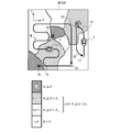
- FIG. 3 is a plan view showing an example of a traveling area of the utility vehicle according to the present embodiment.
- FIG. 4 is a flowchart for exemplifying the flow of travel control processing according to the road surface condition in the autonomous travel mode of the present embodiment.
- FIG. 1 is a schematic left side view showing a utility vehicle according to an embodiment.
- the utility vehicle 1 shown in FIG. 1 (hereinafter, simply referred to as a vehicle 1) includes a pair of left and right front wheels 2 and a pair of left and right rear wheels 3.
- the front wheels 2 and the rear wheels 3 support the vehicle body frame 4.
- the vehicle body frame 4 is a pipe frame formed by connecting a plurality of pipes to each other.
- the vehicle body frame 4 supports the front row seat 5A and the rear row seat 5B.
- the front row seat 5A includes the driver's seat.
- the seats are not limited to two rows and may be one row.
- the vehicle body frame 4 is configured to surround the occupant space C including the front row seat 5A and the rear row seat 5B. That is, the occupant space C is partitioned by the vehicle body frame 4.
- a bonnet 6 is arranged in front of the occupant space C (front row seat 5A).
- the bonnet 6 is supported by the front portion of the vehicle body frame 4 and covers the space between the left and right front wheels 2 so as to be openable and closable from above.
- a front row side door 7A is provided on the side of the front row seat 5A, and a rear row side door 7B is provided on the side of the rear row seat 5B.
- These side doors 7A and 7B are supported by the vehicle body frame 4.
- the side doors 7A and 7B open and close with respect to the vehicle body frame 4 by rotating around a rotation axis provided at the front end portion thereof. As a result, the occupant can get on and off the vehicle 1.
- the side doors 7A and 7B are shown so as to be transparent to the inside (passenger space C side).
- a loading platform 8 is arranged behind the occupant space C (rear row seat 5B).
- the rear portion of the vehicle body frame 4 supports the loading platform 8.
- a drive source 9 supported by the vehicle body frame 4 is arranged below the loading platform 8.
- the drive source 9 is, for example, an engine.
- the drive source 9 may be an electric motor or a combination of an engine and an electric motor.
- the drive source 9 drives the drive wheels (front wheels 2 and / or rear wheels 3).
- a first operator 10 including an accelerator pedal and a brake pedal is provided in front of and below the driver's seat (driver's foot area). By operating the accelerator pedal, the driving force of the driving source 9 changes. Brake devices (not shown) are provided on the front wheels 2 and the rear wheels 3, and the vehicle 1 is decelerated by operating the brake pedal. In this way, the first operator 10 is configured as an operator for accelerating and decelerating the vehicle 1.
- the front wheel 2 is provided with a steering device 11. Further, a steering wheel 12 is provided as a second operator in front of the driver's seat in the front row seat 5A.
- the steering wheel 12 is connected to the steering device 11, and the steering device 11 operates in response to an operation on the steering wheel 12 to steer the front wheels 2.
- the second operator is configured as an operator for changing the direction of the vehicle 1.
- the vehicle 1 is provided with a transmission (not shown) connected between the drive source 9 and the drive wheels.
- the transmission changes the gear ratio or changes the traveling direction (forward or backward) based on an operation on a third operator such as a shift lever (not shown).
- the traveling device 14 for traveling the vehicle 1 includes a front wheel 2, a rear wheel 3, a steering device 11, a drive source 9, a brake device, a transmission device, and the like. Further, the operators for operating the traveling device 14 include a first operator, a second operator, a third operator, and the like.
- the vehicle 1 is provided with a control device 13 for controlling the traveling device 14.
- Various sensors which will be described later, are connected to the control device 13.
- the control device 13 acquires the detected values of various sensors.
- the control device 13 has a processor, a volatile memory, a non-volatile memory (storage), an I / O interface, and the like, and the processor performs arithmetic processing using the volatile memory based on a program stored in the non-volatile memory. As a result, it is configured as an electronic circuit that realizes various controls.
- FIG. 2 is a block diagram showing an outline of the control system of the utility vehicle shown in FIG. As shown in FIG. 2, various sensors are connected to the control device 13. The sensor detects the vehicle state of the traveling system including the operator and the traveling device 14.
- the sensors include, for example, an accelerator opening sensor 15, a brake amount sensor 16, a steering angle sensor 17, a drive source rotation speed sensor 18, a vehicle speed sensor 19, a wheel rotation speed sensor 20, a suspension stroke sensor 21, a pitch angle sensor 22, and a roll angle. Includes sensor 23 and the like.
- the vehicle 1 may include all of these sensors, may include some of these sensors, or may include sensors other than these sensors.
- the accelerator opening sensor 15 detects the amount of operation of the accelerator pedal.
- the brake amount sensor 16 detects the operation amount of the brake pedal.
- the steering angle sensor 17 detects the operation direction and the operation amount of the steering wheel 12.
- the drive source rotation speed sensor 18 detects the rotation speed of the output shaft of the drive source 9.
- the vehicle speed sensor 19 detects the speed of the vehicle 1.
- the wheel rotation speed sensor 20 detects the rotation speed of each of the wheels 2 and 3.
- the wheel rotation speed sensor 20 may be provided on each of the four wheels (left and right front wheels 2 and left and right rear wheels 3). Instead of providing the vehicle speed sensor 19, the vehicle speed may be obtained from the rotation speed of the wheels of the drive wheels (for example, the rear wheel 3).
- the suspension stroke sensor 21 detects the amount of expansion and contraction of the suspension (not shown) provided for each of the wheels 2 and 3 of the vehicle 1.
- the suspension stroke sensor 21 may be provided on each of the four suspensions provided on each of the four wheels.
- the pitch angle sensor 22 detects the rotation angle of the vehicle 1 around the pitch axis (virtual rotation axis extending in the vehicle width direction) of the vehicle 1. Instead of providing the pitch angle sensor 22, the pitch angle may be detected from the difference in the amount of expansion and contraction between the front suspension and the rear suspension detected by the suspension stroke sensor 21.
- the roll angle sensor 23 detects the rotation angle of the vehicle 1 around the roll axis of the vehicle 1 (a virtual rotation axis extending in the front-rear direction of the vehicle). Instead of providing the roll angle sensor 23, the roll angle may be detected from the difference in the amount of expansion and contraction between the right suspension and the left suspension detected by the suspension stroke sensor 21.
- the control device 13 controls the traveling device 14 so that autonomous traveling that does not require manned operation can be performed in a predetermined traveling area.
- a mode switching unit 50 is connected to the control device 13.
- the mode switching unit 50 has a manned operation mode in which the operation according to the operation to the operator is performed, and an autonomous driving mode in which the control device 13 performs autonomous driving in accordance with a predetermined travel route without the operation to the operator. Switch.
- the mode switching unit 50 transmits a mode switching signal based on switching by a switch, various authentication operations, and the like to the control device 13.
- the control device 13 switches the control mode between the manned operation mode and the autonomous driving mode according to the received mode switching signal.
- the control device 13 controls the traveling device 14 in response to inputs to various controls operated by the driver. For example, the control device 13 adjusts the output of the drive source 9 (in the case of an engine, control of the throttle opening, etc.) based on the accelerator opening detected by the accelerator opening sensor 15 in response to the driver's operation on the accelerator pedal. )I do. Further, for example, the control device 13 adjusts the steering angle of the steering device 11 based on the steering angle and the steering direction detected by the steering angle sensor 17 in response to the driver's operation on the steering wheel 12.
- the control device 13 performs autonomous travel according to a predetermined travel route without requiring an operation on the operator.
- the vehicle 1 includes a front space detecting unit 29 for detecting the state of the vehicle (front traveling space of the vehicle 1) and a vehicle position detecting unit 30 for detecting the position of the vehicle.
- the front space detection unit 29 includes, for example, at least one such as a camera, various radars, and a laser sensor.
- the control device 13 analyzes the front space based on the image data of the front space captured by the camera and / or the distance data measured by various radars or laser sensors.
- the control device 13 controls the traveling device 14 based on the analysis result of the front space. For example, when there is an obstacle in front, the control device 13 controls the drive source 9 and / or the brake device (not shown) so as to decelerate or stop the vehicle 1, or to change the traveling direction of the vehicle 1.
- the steering device 11 is controlled.
- the own vehicle position detection unit 30 is provided with, for example, a GPS antenna or the like.
- the storage device of the control device 13 stores preset travel route data.
- the control device 13 reads out the data of the traveling route in the autonomous driving mode, and controls the traveling device 14 so as to travel along the traveling route based on the information of the own vehicle position from the own vehicle position detecting unit 30. Further, the control device 13 finely adjusts the traveling route based on the above-mentioned analysis result of the front space. For example, when there is an obstacle in front, the control device 13 sets the reroute of the traveling route.
- the vehicle 1 is provided with a route setting device 41 for setting a travel route for autonomous travel.
- the route setting device 41 may be configured as a control block of the control device 13, or may be configured by another computer.
- the route setting device 41 may be provided in the vehicle 1 or a mobile terminal (tablet terminal) capable of communicating via a communication network. ) Etc. may be configured by a computer.
- the route setting device 41 is configured to be able to communicate with the outside via a communication network, and is connected to a data receiving unit 42 that receives predetermined data from the outside.
- the travel route data is information set and input via a predetermined server device, for example, by a user setting and inputting a travel route to a mobile terminal (tablet terminal or the like) capable of communicating with the vehicle 1 via a communication network in advance. Is transmitted to the control device 13 of the vehicle 1.
- the vehicle 1 may be equipped with an operation terminal connected to the control device 13 for the user to set and input a travel route.
- the mode switching unit 50 has a manned operation mode in which the operation according to the operation to the operator is performed, and an autonomous driving mode in which the mode switching unit 50 performs autonomous driving in which the operation to the operator is not required according to a predetermined travel route. Is switched. Therefore, when performing periodic work or the like, by executing the autonomous driving mode, manned operation is unnecessary and the work load can be reduced. Further, it can be used as a manned operation utility vehicle 1 by executing a manned operation mode as needed, such as when performing temporary work. Therefore, according to the above configuration, it is possible to enable flexible operation in the utility vehicle 1 capable of autonomous driving according to a predetermined traveling route.
- the vehicle 1 can get on the occupant space C even in the autonomous traveling mode. That is, the vehicle 1 can travel either manned or unmanned in the autonomous traveling mode.
- the vehicle 1 is activated by the user performing a predetermined activation operation.
- the mode switching unit 50 transmits a mode switching signal for switching to the autonomous driving mode to the control device 13.
- the control device 13 causes the route setting device 41 to execute the travel route setting process (travel route setting program).
- the travel route may be set by reading it out. If the travel route is not stored in the storage device, or if the travel route is different from the previous one, the travel route may be reset. In this case, for example, the route may be set by a mobile terminal capable of wirelessly or wiredly communicating with the vehicle 1.
- the route setting device 41 executes a travel route setting program, and sets a travel route from input information such as waypoints and destinations, information on the position of the own vehicle, and terrain information stored in advance corresponding to a map. do. Further, for example, when the vehicle 1 is used for patrol security in a predetermined area, a travel route in which the route setting device 41 travels over the entire patrol area by setting and inputting the patrol area on a map. May be configurable. After setting the travel path, the control device 13 starts autonomous travel.
- the control device 13 controls the traveling device 14 according to the road surface condition in front of the traveling direction of the own vehicle position during autonomous traveling in the autonomous traveling mode. For this purpose, the control device 13 acquires road surface condition data in the traveling region.
- the road surface condition data divides the traveling area into a plurality of predetermined road surface condition levels.
- the road surface condition data is stored in a storage device (server device, mobile terminal, etc.) outside the vehicle 1 capable of communicating through a storage device in the vehicle 1 or a communication network.
- FIG. 3 is a plan view showing an example of a traveling area of the utility vehicle according to the present embodiment.
- FIG. 4 is a flowchart for exemplifying the flow of travel control processing according to the road surface condition in the autonomous travel mode of the present embodiment.
- the vehicle 1 is used to perform a predetermined work in the work area WA (for example, a material collection site).
- the vehicle 1 performs, for example, material transportation work or work area WA monitoring work (patrol travel) in the work area WA.
- the work area WA is preset as the travel area SA of the vehicle 1.
- the path of reciprocating movement between the first position P1 and the second position P2 in the work area WA (the first path R1 from the first position P1 to the second position P2 and the first position P1 from the second position P2).
- the second route R2) to to can be set as a travel route during autonomous travel.
- the first position P1 is set to the outside carry-out place of the material
- the second position P2 is set to the material storage place.
- the vehicle 1 in the autonomous traveling mode moves from the first position P1 to the second position P2 and stops.
- the material is loaded onto the loading platform 8 of the vehicle 1.
- the vehicle 1 moves from the second position P2 to the first position P1 and stops.
- materials are loaded and unloaded.
- the vehicle 1 in the autonomous traveling mode repeatedly reciprocates between the first position P1 and the second position P2.
- the traveling route during autonomous traveling is a traveling route in which the monitoring work is performed by patrolling the work area WA on a predetermined traveling route starting from the third position P3 of the working area WA.
- the third travel path R3 includes, for example, a meandering section M that reciprocates in the first direction X of the work area WA and moves in the second direction Y at the time of turning.
- the work area WA set as the traveling area SA has a plurality of predetermined road surface condition levels (Lv1, Lv2-1, Lv2-2, Lv3) (4 in the example of FIG. 3). It is divided into.
- the road surface condition data includes data indicating the road surface condition level at each position of the traveling area SA.
- the control device 13 reads out the travel route and road surface condition data set from the route setting device 41 (step S1). For example, the reading of the road surface condition data is performed by sequentially reading out the data portion indicating the road surface condition in the region ahead of the traveling direction of the own vehicle position traveling route.
- the control device 13 determines which of the plurality of road surface condition levels the road surface condition in front of the own vehicle position of the vehicle 1 belongs to from the road surface condition data during autonomous driving (step S2).
- the control device 13 acquires the vehicle position and the traveling direction (direction) of the vehicle 1 from the vehicle position detecting unit 30, and obtains the road surface condition level in the traveling direction front region of the vehicle position in the traveling region SA from the road surface condition data. Inquire.
- the road surface condition level is divided into stages according to the inclination angle ⁇ of the vehicle 1 when the vehicle 1 is traveling.
- the tilt angle of the vehicle may be set as either a pitch angle or a roll angle. Further, the tilt angle of the vehicle may be a three-dimensional angle considering both the pitch angle and the roll angle.
- the first level Lv1 is set in a region where the inclination angle ⁇ is less than the first angle ⁇ 1 when the vehicle 1 travels.
- Second level Lv2 when the vehicle 1 has traveled, the inclination angle theta is set to the first angle theta 1 or more and the first angle theta 1 is greater than the second angle theta region as less than 2.
- the third level Lv3 is set in a region where the inclination angle ⁇ is equal to or greater than the second angle ⁇ 2 when the vehicle 1 travels.
- the second level Lv2 is further divided into a first sub-level Lv2-1 and a second sub-level Lv2-2.
- the first sub-level Lv2-1 seems to have an inclination angle ⁇ of 1 or more and less than a sub-angle ⁇ S larger than the first angle ⁇ 1 and smaller than the second angle ⁇ 2 when the vehicle 1 travels. Area is set.
- the second sub-level Lv2-2 is set in a region where the inclination angle ⁇ is equal to or greater than the sub-angle ⁇ S and less than the second angle ⁇ 2 when the vehicle 1 travels.
- the control device 13 controls the travel device 14 so that the predetermined travel parameters are within the preset allowable range corresponding to each of the plurality of road surface condition levels (steps S3 to S7). More specifically, the control device 13 determines whether or not the road surface condition level is the first level Lv1 (step S3). When the control device 13 determines that the road surface condition level is the first level Lv1 (Yes in step S3), the control device 13 performs normal control (without limitation) (step S4).
- the control device 13 determines whether or not the road surface condition level is the second level Lv2 (step S5).
- the control device 13 determines that the road surface condition level is the second level Lv2 (Yes in step S5), the control device 13 performs traveling restriction control (step S6).
- the control device 13 controls to avoid approaching (step S7).
- the following example shows a case where the traveling parameters include speed and steering angle.
- the control device 13 controls the traveling device 14 without speed limitation and steering angle limitation based on the road surface condition level when the road surface condition level is the first level Lv1.
- normal traveling control is performed in the road surface condition where the posture of the vehicle 1 is stable.
- it is permissible to limit the speed other than the road surface condition level such as when the vehicle 1 is cornering or when traveling in a predetermined speed limit region or the like.
- the control device 13 controls the traveling device 14 so that the speed of the vehicle 1 becomes equal to or less than the first reference speed V1 when the road surface condition level is the second level Lv2. Further, the control device 13 controls the traveling device 14 so that the range of the steering angle becomes equal to or less than the predetermined reference range ⁇ in addition to the above speed limit when the road surface condition level is the second sub-level Lv2-2. do. The control device 13 does not limit the steering angle when the road surface condition level is the first sub-level Lv2-1 or the first level Lv1.
- the speed is limited in the road surface condition where the vehicle 1 passes through an obstacle (rocky place, depression, etc.) that can be run, or passes on a slope above a certain level.
- the vehicle 1 can be overturned by steering at a large steering angle when the vehicle 1 is tilted when passing through an obstacle or the like. The sex can be reduced.
- the different restriction controls may be an increase / decrease in the type (number) of the restricted driving parameters, an increase / decrease in the allowable range in the same driving parameters, or a combination thereof.
- the control device 13 controls the traveling device 14 so as to avoid the entry of the vehicle 1 into the region when the road surface condition level is the third level Lv3. For example, when the vehicle 1 in FIG. 3 is located at the position Pa, the control device 13 determines the road surface condition level in the region Aa ahead of the vehicle 1 in the traveling direction. Since the road surface condition level of the region Aa is the third level Lv3, the control device 13 does not enter the region Aa but steers. The route setting device 41 resets the traveling route accordingly.
- the traveling device 14 when the vehicle 1 is autonomously traveling, the traveling device 14 is controlled differently according to the road surface condition level ahead of the traveling direction of the own vehicle position. Therefore, in a place where the road surface condition is bad, the traveling control in autonomous driving such as traveling at a low speed can be changed from the control in the place where the road surface condition is good. Therefore, in the vehicle 1 capable of traveling on rough terrain, it is possible to appropriately control autonomous traveling according to the road surface condition.
- the allowable range of driving parameters can be set not only at the upper limit but also at the lower limit.
- the control device 13 sets an upper limit value of the speed and a lower limit value of the speed (minimum speed in steady driving) when the road surface condition level is the second level Lv2 for which the traveling restriction control should be performed. You may. As a result, it is possible to perform appropriate traveling control even on a road surface where the vehicle 1 may be stuck when traveling at a low speed. That is, the possibility that the vehicle 1 is stuck can be reduced.
- the driving parameters to be controlled are not limited to the above example.
- the traveling parameters may include acceleration, gear ratio, suspension damping force, vehicle height, and the like, in addition to the above speed and steering angle.
- the control device 13 controls the traveling device 14 so that the acceleration becomes equal to or less than a predetermined reference acceleration when the road surface condition level is the second level Lv2 for which the traveling restriction control should be performed. This makes it possible to prevent slipping due to sudden acceleration on a slippery road surface.
- the vehicle 1 is provided with a transmission (having a plurality of stages) capable of selectively switching a plurality of gear ratios (ratio of the rotation speed of the output shaft of the drive source 9 to the rotation speed of the output shaft of the transmission).
- the control device 13 is a traveling device so that the road surface condition level is equal to or lower than the reference gear ratio (reference stage or higher) among the plurality of gear ratios when the road surface condition level is the second level Lv2 for which the traveling restriction control should be performed. 14 is controlled. This makes it possible to prevent slipping due to an increase in output torque on a slippery road surface.
- the control device 13 determines that the road surface condition level is the second level Lv2 for which the traveling restriction control should be performed.
- the traveling device 14 is controlled so that the damping force of the suspension is low.
- the control device 13 is a traveling device so that the vehicle height becomes high when the road surface condition level is the second level Lv2 for which the traveling restriction control should be performed. 14 is controlled.
- the control device 13 can acquire predetermined data regarding the vehicle loading status or the external environment of the vehicle 1 from the data receiving unit 42, and can correct the permissible range associated with the road surface condition level based on the acquired data. For example, the vehicle 1 detects the weight of the load on the loading platform 8 and / or the number of seats on the seats 5A and 5B. The detected weight of the cargo and / or the number of seated persons is sent to the control device 13 via the data receiving unit 42.
- the control device 13 is, for example, in the traveling restriction control when the road surface condition level is the second level Lv2 when the weight of the load is equal to or more than the predetermined reference weight and / or when the number of seated persons is equal to or more than the predetermined reference number. Change the permissible range of driving parameters to be controlled narrower. For example, in the above example, when the road surface condition level is the first sub-level Lv2-1, the control device 13 changes the permissible speed range to the second reference speed V2 or less, which is lower than the first reference speed V1.
- the control device 13 raises the road surface condition level by one level (a level at which the limit becomes stricter by one level). ) May be changed. That is, in the above example, when the road surface condition level is the first sub-level Lv2-1, the control device 13 performs the traveling limitation control of the second sub-level Lv2-2, that is, the speed limitation and the steering angle limitation. You may go. Further, when the road surface condition level is the second sub-level Lv2-2, the control device 13 may perform control of the third level Lv3, that is, control for avoiding the entry of the vehicle 1 into the area.
- the vehicle 1 includes, for example, weather, temperature, atmospheric pressure, season, date and time, region (climate zone), ground type (muddy area, wet area, sandy beach, desert, etc.) as data on the external environment of the vehicle 1. obtain.
- One of these data may be used, or a plurality of them may be used in combination.
- Data related to the external environment (for example, weather, season, date and time, area, etc.) are stored in, for example, a server device that is communicated and connected to the data receiving unit 42 of the vehicle 1 via a communication network, and is stored in the data receiving unit 42 from the server device.
- Sent Alternatively, the data related to the external environment (for example, temperature, atmospheric pressure, road surface condition, etc.) may be, for example, a value detected by a sensor provided in the vehicle 1.
- the control device 13 has an allowable range of traveling parameters to be controlled in the traveling restriction control when the road surface condition level is the second level Lv2 when the weather is rainy or the atmospheric pressure is equal to or lower than a predetermined reference atmospheric pressure. May be changed to a narrower level, or the road surface condition level may be changed to a higher level. Further, for example, when the control device 13 is traveling on a muddy ground or the like where stacking is likely to occur, or when the air temperature is below a predetermined reference temperature (for example, below the freezing point), the control device 13 sets the minimum speed during steady traveling to a third. The reference speed may be set to V3 or higher.
- the vehicle 1 includes a road surface condition estimation device 43 that creates road surface condition data.
- the road surface condition estimation device 43 may be configured as a functional block of the control device 13, or may be configured as a calculation device different from the control device 13.
- the road surface condition estimation device 43 estimates the road surface condition at the position of the own vehicle from a predetermined driving index, and determines which of the plurality of road surface condition levels set in advance from the estimation result, and thereby obtains the road surface condition data. create.
- the travel index is at least one index indicating the travel state of the vehicle 1, and is acquired by the travel index acquirer 44.
- the traveling index is a pitch angle and / or a roll angle indicating the posture of the vehicle 1. Therefore, the travel index acquirer 44 includes the pitch angle sensor 22 and / or the roll angle sensor 23. In addition to or instead of this, the travel index acquirer 44 may include various other sensors 15 to 21 depending on the travel index to be acquired.
- FIG. 2 illustrates that the travel index acquirer 44 includes various sensors 15 to 23 and a digital model forming unit 45 described later, but a sensor or the like for obtaining a desired travel index is the travel index acquirer 44. The other sensor does not have to function as the travel index acquirer 44.
- the travel index may include a first travel index indicating the posture of the vehicle 1.
- the travel index may include a second travel index indicating the force exerted on the front wheels 2 and / or the rear wheels 3 (hereinafter, the force on the wheels).
- the first running index indicating the posture of the vehicle 1 can be obtained by directly measuring the pitch angle and / or the roll angle as described above. Further, the travel index acquirer 44 may be one or more of the accelerator opening, the brake amount, the steering angle, the rotation speed of the output shaft of the drive source 9, the vehicle speed, the wheel rotation speed, the stroke amount of the suspension, and the like at that time. The first running index may be corrected by using the index.
- the second running index indicating the force on the wheels of the vehicle 1 includes, for example, the slip ratio of each wheel.
- the slip ratio is obtained by measuring the vehicle speed and the wheel rotation speed, obtaining the deviation of the wheel rotation speed with respect to the vehicle speed, and dividing the deviation by the vehicle speed.
- the traveling index acquirer 44 may use one or more of the accelerator opening, the brake amount, the steering angle, the rotation speed of the output shaft of the drive source 9, the suspension stroke amount, the pitch angle, the roll angle, and the like at that time.
- the second running index may be corrected by using the index.
- the travel index acquirer 44 may include a digital model forming unit 45 that forms a digital model of the vehicle 1.
- the travel index acquirer 44 detects at least one vehicle state value indicating the state of the vehicle 1.
- the digital model forming unit 45 forms a digital model regarding the running state of the vehicle 1 from at least one vehicle state value.
- the travel index acquirer 44 extracts a travel index from the digital model.
- the digital model forming unit 45 may form a digital model of the vehicle 1 by using the state values related to the posture of the vehicle 1 such as the pitch angle and the roll angle as the vehicle state values.
- the travel index acquirer 44 may extract the grip force on each of the wheels 2 and 3 of the formed digital model as a travel index.
- the travel index acquirer 44 may correct the travel index based on the detection result by the front space detection unit 29 when acquiring the travel index. For example, when the front space detection unit 29 is a camera, the travel index acquirer 44 analyzes the image in front of the vehicle 1 captured by the front space detection unit 29 to estimate the friction coefficient of the travel road surface. The travel index acquirer 44 uses the obtained friction coefficient to correct the travel index measured or obtained from the digital model. Further, for example, the travel index acquirer 44 may analyze the image in front of the vehicle 1 captured by the front space detection unit 29 to estimate the posture of the vehicle 1 and correct the travel index based on the estimation.
- the road surface condition estimation device 43 estimates the road surface condition in the travel route traveled in the manned operation mode, and creates the road surface condition data by associating the travel route with the road surface condition level.
- the travel index acquirer 44 acquires the travel index at the position of the own vehicle while traveling in the manned travel mode.
- the road surface condition estimation device 43 estimates the road surface condition from the traveling index at the own vehicle position, and determines which of the plurality of road surface condition levels the road surface condition at the own vehicle position belongs to.
- the control device 13 stores the road surface condition level of the own vehicle position obtained by the determination in association with the data of the own vehicle position.
- the control device 13 may overwrite the new data as the data at that position, or average the accumulated data and the new data. You may update by performing the processing of.
- the traveling area SA an area that has not traveled in the past is set as a non-traveling area.
- the storage location of the road surface condition data may be a storage device inside the vehicle 1 or a storage device (server device, mobile terminal, etc.) outside the vehicle 1 capable of communicating through the communication network.
- the road surface condition estimation device 43 maps the road surface condition level in the predetermined traveling area SA by storing the road surface condition level in the traveling route traveled in the manned operation mode in association with the own vehicle position.
- the mapped data is stored as road surface condition data (road surface condition map).
- the road surface condition estimation device 43 may apply the adjacent road surface condition data by analogy to the road surface condition of the region portion that is not traveling in the manned operation mode in the traveling region SA, or may apply the adjacent road surface condition data by analogy, or may apply the adjacent road surface condition data to the non-traveling region (third level Lv3). ) May be used.
- the road surface condition estimation device 43 may estimate the road surface condition in the traveling route when the vehicle 1 autonomously travels using the road surface condition data created in the manned operation mode, and may update the road surface condition data.
- the vehicle 1 is driven in the autonomous driving mode without performing the driving control in consideration of the road surface condition, so that the road surface condition estimation device 43 acquires the driving index and obtains the driving index.
- the road surface condition may be estimated based on the estimation.
- the control device 13 drives the traveling device 14 so that the vehicle 1 autonomously travels according to a predetermined traveling pattern or a traveling route set by the user.
- the road surface condition estimation device 43 estimates the road surface condition at that time, and creates road surface condition data by associating the traveling route with the road surface condition level. For example, if the vehicle 1 falls, the posture of the vehicle 1 (roll angle, pitch angle, etc.) exceeds the standard range, or the vehicle 1 becomes unable to travel due to a stack or the like.
- the road surface condition level at the position is set to the third level Lv3.
- the road surface condition estimation device 43 may estimate the road surface condition in the traveling route when traveling in the autonomous traveling mode using the road surface condition data, and may update the road surface condition data.
- the road surface condition data may be created by performing a running simulation of a virtual vehicle imitating the vehicle 1.
- the driving simulation may be performed by the road surface condition estimation device 43, a computer outside the vehicle 1 capable of communicating with the vehicle 1 through the communication network, or an independent computer that does not communicate with the vehicle 1.
- the road surface condition data obtained as a result may be transferred to the storage device of the vehicle 1 or the like via a recording medium or the like.
- topographical data in the running area SA is prepared. Topographical data is created from, for example, satellite images.
- the computer that performs the running simulation creates a virtual running space based on the road surface shape data in the running area SA. Further, the computer generates a virtual vehicle imitating the vehicle 1 and arranges it in the virtual traveling space.
- the computer performs a driving simulation to drive a virtual vehicle in the generated virtual driving space.
- the traveling state of the virtual vehicle changes according to the terrain change in the virtual traveling space.
- the attitude of the virtual vehicle or the force on the wheels at this time is acquired as a running index, and the road surface condition is estimated.
- the computer creates road surface condition data (road surface condition map) by dividing the virtual traveling space into a plurality of road surface condition levels based on the estimation result of the road surface condition.
- Machine learning can be used in such driving simulations.
- machine learning that classifies into multiple road surface condition levels by supervised learning may be performed.
- different road surface condition levels may be assigned to the road surface condition classifications classified into a plurality of categories by unsupervised learning, and the allowable range of the corresponding driving parameters may be determined.
- the road surface condition data in the virtual traveling space obtained in such a traveling simulation is used as the road surface condition data in the actual traveling area SA. Further, the road surface condition estimation device 43 may estimate the actual road surface condition in the traveling route when traveling in the autonomous traveling mode using the road surface condition data, and may update the road surface condition data.
- the road surface condition level included in the road surface condition data may be set to one dimension based on one viewpoint (posture of the vehicle 1) as in the example shown in FIG. 3, but is two-dimensional by combining a plurality of viewpoints. Or it may be set to more multidimensional.
- road surface condition data having a two-dimensional road surface condition level by combining a one-dimensional type 1 road surface condition level based on the vehicle attitude and a one-dimensional type 2 road surface condition level based on the estimated friction coefficient of the road surface in a matrix. May be generated.
- the control device 13 may limit sudden acceleration. , It is possible to perform control such as limiting the maximum speed at the time of steering. Further, in such a case, it may be muddy or on the water (crossing the river), so that the control device 13 travels at a preset minimum speed or higher in order to prevent the vehicle 1 from getting stuck. You may control it.
- the road surface condition is estimated when the vehicle 1 is running, and data on the external environment at that time (for example, weather, temperature, atmospheric pressure, season, date and time, area, ground type, etc. as described above) are acquired.
- the road surface condition level at that position may be set to a different level according to the index of the external environment.
- the road surface condition level in fine weather is the first sub-level Lv2-1
- the road surface condition level in rainy weather is the second sub-level Lv2-2, and so on. Multiple settings may be made depending on the situation.
- control device 13 may determine the road surface condition level for each of the left and right wheels 2 and 3 as the road surface condition in front of the vehicle 1 in the traveling direction. In this case, for example, the control device 13 detects the roll angle, and when the roll angle is equal to or greater than the reference value, determines that the vehicle 1 is in a state of crossing and advancing with respect to the inclination. When the control device 13 determines that the vehicle 1 is in a state of crossing the inclination and traveling, and the road surface condition level is the second level Lv2 for which the traveling limit control (speed limit) should be performed, the speed limit is applied. In addition, if the steering angle range is limited and it is determined that the vehicle 1 is not in a state of crossing the slope and the road surface condition level is the second level Lv2, the speed is limited but the steering angle is limited. The range may not be limited.
- control device 13 may determine the road surface condition level for each of the four front, rear, left, and right wheels as the road surface condition in front of the vehicle 1 in the traveling direction.
- the road surface condition level (second level Lv2) for which the traveling restriction control is performed includes two sub-levels Lv2-1 and Lv2-2 having different allowable ranges of traveling parameters or types of traveling parameters.
- the road surface condition level (second level Lv2) for performing the travel restriction control may correspond to one control content or may include three or more sub-levels.
- Multiple road surface conditions that can vary the permissible range of driving parameters or the types of driving parameters (possible to perform driving restriction control) include, for example, wet paved roads, gravel roads, farmlands, grasslands, steep slopes, rivers, rocky areas, etc. Includes snow, muddy, sandy beaches, deserts, etc.
- the road surface condition data created in each of the above modes may be used for setting a traveling route. That is, the route setting device 41 may set a traveling route based on the road surface condition data. For example, when a plurality of travel routes can be set when moving the vehicle 1 from the current position to a desired destination, the route setting device 41 sets the road surface condition level to a predetermined level (for example, a second sub-level) in which the vehicle 1 can travel. A travel route with a shorter distance on the travel route that is Lv2-2) or higher is adopted.
- the route setting device 41 sets a travel route that more satisfies the priority condition. For example, when the travel route is set with priority given to distance when the vehicle 1 is moved to a desired destination, the route setting device 41 is at a level where the road surface condition level is somewhat high (for example, the second sub-level Lv2-2) or higher. Allow the adoption of a certain route. Further, for example, when the traveling route is set by giving priority to time when moving the vehicle 1 to a desired destination, the route setting device 41 takes into consideration the speed limit according to the road surface condition level and the arrival time is shorter. Adopt a travel route.
- the route setting device 41 determines that the road surface condition level can be traveled.
- a travel route having a shorter distance on the travel route that is equal to or higher than the level of (for example, the second sub-level Lv2-2) is adopted.
- the route setting device 41 may further set the traveling route so that the state where the road surface condition levels of the left and right road surfaces where the left and right wheels 2 and 3 touch each other is less likely to be different.
- the route group on which the vehicle 1 or the virtual vehicle traveled (does not become inoperable) at the time of creating the road surface condition data by actual traveling or machine learning may be registered as a traveling route candidate.
- the route setting device 41 selects the optimum route from the route group based on the setting data of the travel route such as the destination, or combines a plurality of routes included in the route group and sets it as the travel route. You may.
- the number of changes in the travel route during autonomous travel can be reduced, and efficient travel of the vehicle 1 can be realized.
- the front space detection unit 29 is configured to be able to detect a monitoring target such as a person or an animal by analyzing a captured image, and the front space detection unit 29 detects a monitoring target during autonomous driving or manned operation.
- the control device 13 stores the position of the own vehicle at that time in a storage device or the like as encounter history data.
- the user who gets on the vehicle 1 can perform a predetermined operation input to register the position of the own vehicle at the time of the operation input as a place where the monitoring target is detected.
- the route setting device 41 may change a part or all of the traveling route based on the encounter history data.
- the route setting device 41 may set a traveling route so as to avoid a place where the monitoring target is frequently encountered. This can reduce the risk of contact with humans or animals. Further, it is possible to reduce the possibility that the vehicle 1 is attacked or the cargo is plundered when traveling in a conflict area or an insecure area, for example, for transporting goods.
- the route setting device 41 may set a travel route that preferentially passes through a location where the monitoring target is frequently encountered. Thereby, for example, when traveling for patrol security (monitoring) in the traveling area SA by the vehicle 1 in a vast agricultural land or a forest, it is possible to set a traveling route with high discovery efficiency.
- the front space detection unit 29 is configured to be able to detect light emission by analyzing an captured image during nighttime driving, and the front space detection unit 29 is configured to be capable of detecting light emission during nighttime autonomous driving or manned operation.
- the control device 13 stores the position of the own vehicle at that time in a storage device or the like as light emission history data.
- the user who gets on the vehicle 1 can perform a predetermined operation input to register the position of the own vehicle at the time of the operation input as a place where light emission is detected.
- the route setting device 41 may change a part or all of the traveling route based on the light emission history data.
- the vehicle 1 may include a first control device (first ECU) that controls the vehicle 1 in the manned operation mode and a second control device (second ECU) that controls the vehicle 1 in the autonomous driving mode.
- first ECU first ECU
- second ECU second ECU
- the vehicle 1 capable of traveling by manned operation is exemplified, but the control in the autonomous traveling mode of the above-described embodiment may be applied to the vehicle 1 dedicated to autonomous driving.
- the vehicle 1 provided with the road surface condition estimation device 43 is exemplified, but the road surface condition estimation device 43 may not be provided. That is, the control device 13 acquires the road surface condition data from the storage unit of the vehicle 1 or an external storage device, determines which of the plurality of road surface condition levels the road surface condition in front of the vehicle position in the traveling direction belongs to. Other configurations may be omitted as long as the travel device 14 is configured to control the travel device 14 so that the predetermined travel parameters are within the preset tolerances corresponding to each of the plurality of road surface condition levels. ..
- the road surface condition data in the above embodiment may be common data for a plurality of vehicle types. However, when the traveling ability differs depending on the vehicle type, the allowable range of the traveling parameter corresponding to one road surface condition level or the type of the traveling parameter may differ depending on the vehicle type.
- the speed is limited at the first sub-level Lv2-1, and the running limit and the steering range are limited at the second sub-level Lv2-2.
- the running is controlled to do.
- the speed is limited to a lower speed or less at the first sub-level Lv2-1 and the steering range is limited, and the second sub-level Lv2-2 is restricted. Then, the control for avoiding the entry of the vehicle 1 into the area may be performed.
- the running levels divided into a plurality of levels based on the running ability of the vehicle 1 may be stored in a storage device or the like as data to be read when the control device 13 performs running control.
- the control device 13 may determine the travel control content corresponding to the road surface condition level and the travel level by reading the travel level of the vehicle 1 after determining the road surface condition level.
Landscapes
- Engineering & Computer Science (AREA)
- Mechanical Engineering (AREA)
- Transportation (AREA)
- Automation & Control Theory (AREA)
- Physics & Mathematics (AREA)
- Mathematical Physics (AREA)
- Remote Sensing (AREA)
- Radar, Positioning & Navigation (AREA)
- Chemical & Material Sciences (AREA)
- Combustion & Propulsion (AREA)
- Human Computer Interaction (AREA)
- General Physics & Mathematics (AREA)
- Aviation & Aerospace Engineering (AREA)
- Control Of Driving Devices And Active Controlling Of Vehicle (AREA)
- Control Of Position, Course, Altitude, Or Attitude Of Moving Bodies (AREA)
- Traffic Control Systems (AREA)
Priority Applications (5)
| Application Number | Priority Date | Filing Date | Title |
|---|---|---|---|
| PCT/JP2020/021165 WO2021240742A1 (ja) | 2020-05-28 | 2020-05-28 | ユーティリティビークル |
| US17/927,353 US12344224B2 (en) | 2020-05-28 | 2020-05-28 | Utility vehicle controllable within permissible range based on determined road condition level |
| EP20937786.0A EP4160568B1 (en) | 2020-05-28 | 2020-05-28 | Utility vehicle |
| CN202080101384.XA CN115552497B (zh) | 2020-05-28 | 2020-05-28 | 多用途车 |
| JP2022527410A JP7437500B2 (ja) | 2020-05-28 | 2020-05-28 | ユーティリティビークル |
Applications Claiming Priority (1)
| Application Number | Priority Date | Filing Date | Title |
|---|---|---|---|
| PCT/JP2020/021165 WO2021240742A1 (ja) | 2020-05-28 | 2020-05-28 | ユーティリティビークル |
Publications (1)
| Publication Number | Publication Date |
|---|---|
| WO2021240742A1 true WO2021240742A1 (ja) | 2021-12-02 |
Family
ID=78723179
Family Applications (1)
| Application Number | Title | Priority Date | Filing Date |
|---|---|---|---|
| PCT/JP2020/021165 Ceased WO2021240742A1 (ja) | 2020-05-28 | 2020-05-28 | ユーティリティビークル |
Country Status (5)
| Country | Link |
|---|---|
| US (1) | US12344224B2 (https=) |
| EP (1) | EP4160568B1 (https=) |
| JP (1) | JP7437500B2 (https=) |
| CN (1) | CN115552497B (https=) |
| WO (1) | WO2021240742A1 (https=) |
Families Citing this family (3)
| Publication number | Priority date | Publication date | Assignee | Title |
|---|---|---|---|---|
| JP2024024349A (ja) * | 2022-08-09 | 2024-02-22 | 株式会社Subaru | 車両制御装置 |
| JP2024112485A (ja) * | 2023-02-08 | 2024-08-21 | トヨタ自動車株式会社 | 異常検知装置、異常検知方法及び異常検知用コンピュータプログラム |
| JP2025177619A (ja) * | 2024-05-24 | 2025-12-05 | Astemo株式会社 | 電子制御装置及び環境認識方法 |
Citations (6)
| Publication number | Priority date | Publication date | Assignee | Title |
|---|---|---|---|---|
| JP2005215742A (ja) * | 2004-01-27 | 2005-08-11 | Yanmar Co Ltd | 農業用作業車 |
| JP2008185418A (ja) * | 2007-01-29 | 2008-08-14 | Toyota Motor Corp | 道路形状算出装置及び車両センサ補正装置 |
| WO2013122065A1 (ja) * | 2012-02-14 | 2013-08-22 | 日立建機株式会社 | 路面管理システム |
| JP2018120491A (ja) * | 2017-01-27 | 2018-08-02 | ヤンマー株式会社 | 経路生成システム、及びそれによって生成された経路に沿って作業車両を走行させる自律走行システム |
| JP2019169058A (ja) * | 2018-03-26 | 2019-10-03 | ヤンマー株式会社 | 作業車両の走行制御システム |
| JP2020013379A (ja) | 2018-07-19 | 2020-01-23 | 株式会社日立製作所 | 車両運行システム |
Family Cites Families (16)
| Publication number | Priority date | Publication date | Assignee | Title |
|---|---|---|---|---|
| JP4112738B2 (ja) | 1999-04-20 | 2008-07-02 | ヤンマー農機株式会社 | 移動農機 |
| JP4403759B2 (ja) | 2003-09-02 | 2010-01-27 | カシオ計算機株式会社 | ナビゲーション装置、ナビゲーションシステム、及び、プログラム |
| JP2009006884A (ja) * | 2007-06-28 | 2009-01-15 | Nissan Motor Co Ltd | 能動型サスペンション、及び車両の姿勢変化抑制方法 |
| JP2009205652A (ja) | 2008-02-29 | 2009-09-10 | Nec Corp | 移動体制御システム及び移動体制御方法 |
| US8126642B2 (en) * | 2008-10-24 | 2012-02-28 | Gray & Company, Inc. | Control and systems for autonomously driven vehicles |
| CA3014660C (en) * | 2016-02-15 | 2021-08-17 | Allstate Insurance Company | Early notification of non-autonomous area |
| US10699347B1 (en) * | 2016-02-24 | 2020-06-30 | Allstate Insurance Company | Polynomial risk maps |
| CN110546698A (zh) * | 2017-06-27 | 2019-12-06 | 本田技研工业株式会社 | 车辆控制装置 |
| JP7027142B2 (ja) | 2017-12-06 | 2022-03-01 | ヤンマーパワーテクノロジー株式会社 | 作業車両用の目標経路生成システム |
| JP6628819B2 (ja) * | 2018-01-15 | 2020-01-15 | 本田技研工業株式会社 | 車両走行制御装置 |
| SE542784C2 (en) * | 2018-02-08 | 2020-07-07 | Scania Cv Ab | Method and a control device for determining vehicle operation of at least one vehicle |
| CN109733391A (zh) * | 2018-12-10 | 2019-05-10 | 北京百度网讯科技有限公司 | 车辆的控制方法、装置、设备、车辆及存储介质 |
| US10852746B2 (en) * | 2018-12-12 | 2020-12-01 | Waymo Llc | Detecting general road weather conditions |
| US11144053B2 (en) * | 2019-04-04 | 2021-10-12 | Toyota Research Institute, Inc. | Controlling driving condition components of an autonomous vehicle based on a current driving mode and current conditions |
| JP2021022319A (ja) * | 2019-07-30 | 2021-02-18 | トヨタ自動車株式会社 | 車両走行制御装置 |
| US20200101974A1 (en) * | 2019-08-12 | 2020-04-02 | Lg Electronics Inc. | Device and method for selecting optimal travel route based on driving situation |
-
2020
- 2020-05-28 CN CN202080101384.XA patent/CN115552497B/zh active Active
- 2020-05-28 US US17/927,353 patent/US12344224B2/en active Active
- 2020-05-28 WO PCT/JP2020/021165 patent/WO2021240742A1/ja not_active Ceased
- 2020-05-28 JP JP2022527410A patent/JP7437500B2/ja active Active
- 2020-05-28 EP EP20937786.0A patent/EP4160568B1/en active Active
Patent Citations (6)
| Publication number | Priority date | Publication date | Assignee | Title |
|---|---|---|---|---|
| JP2005215742A (ja) * | 2004-01-27 | 2005-08-11 | Yanmar Co Ltd | 農業用作業車 |
| JP2008185418A (ja) * | 2007-01-29 | 2008-08-14 | Toyota Motor Corp | 道路形状算出装置及び車両センサ補正装置 |
| WO2013122065A1 (ja) * | 2012-02-14 | 2013-08-22 | 日立建機株式会社 | 路面管理システム |
| JP2018120491A (ja) * | 2017-01-27 | 2018-08-02 | ヤンマー株式会社 | 経路生成システム、及びそれによって生成された経路に沿って作業車両を走行させる自律走行システム |
| JP2019169058A (ja) * | 2018-03-26 | 2019-10-03 | ヤンマー株式会社 | 作業車両の走行制御システム |
| JP2020013379A (ja) | 2018-07-19 | 2020-01-23 | 株式会社日立製作所 | 車両運行システム |
Non-Patent Citations (1)
| Title |
|---|
| See also references of EP4160568A4 |
Also Published As
| Publication number | Publication date |
|---|---|
| EP4160568A4 (en) | 2024-04-10 |
| US20230202451A1 (en) | 2023-06-29 |
| EP4160568A1 (en) | 2023-04-05 |
| JPWO2021240742A1 (https=) | 2021-12-02 |
| CN115552497B (zh) | 2025-03-25 |
| US12344224B2 (en) | 2025-07-01 |
| JP7437500B2 (ja) | 2024-02-22 |
| CN115552497A (zh) | 2022-12-30 |
| EP4160568B1 (en) | 2025-12-10 |
Similar Documents
| Publication | Publication Date | Title |
|---|---|---|
| US20230365136A1 (en) | Road friction and wheel slippage assessment for autonomous vehicles | |
| CN112739559B (zh) | 使用压力设定点控制车辆悬挂系统 | |
| US12522211B1 (en) | Modifying speed of an autonomous vehicle based on traffic conditions | |
| US11868133B1 (en) | Avoiding blind spots of other vehicles | |
| US10800403B2 (en) | Autonomous ride dynamics comfort controller | |
| JP6970807B2 (ja) | 移動体制御装置 | |
| EP4031426B1 (en) | Method and system for autonomous driving of vehicles | |
| CN107097780B (zh) | 启用和停用自动驾驶 | |
| US20250014357A1 (en) | Long-range object detection, localization, tracking and classification for autonomous vehicles | |
| CA3093436A1 (en) | System and method for avoiding contact between autonomous and manned vehicles caused by loss of traction | |
| US10589742B2 (en) | Vehicle snow level response | |
| US11453387B1 (en) | Surface characterization with active suspension | |
| US10442334B2 (en) | Tilting a human support surface in a vehicle | |
| US11414093B2 (en) | System and method for transitioning a vehicle from an autonomous mode in response to a handover event | |
| JP7437500B2 (ja) | ユーティリティビークル | |
| US11591011B1 (en) | Dynamic vehicle steering and/or suspension constraints | |
| AU2024200931A1 (en) | Road surface condition obtaining system | |
| CN114080341A (zh) | 联系远程操作员的技术 | |
| US11498564B2 (en) | Controlling a vehicle that is skidding | |
| US11175667B2 (en) | System and method for vehicle integrated stability control using perceived yaw center | |
| KR102173021B1 (ko) | 자율 주행 장치 및 방법 | |
| US12145521B2 (en) | Lateral vehicle position and seat orientation control | |
| US12545118B1 (en) | Torque distribution-based deceleration | |
| CN119063748A (zh) | 用于路线选择目的的计算转弯成本的系统和方法 |
Legal Events
| Date | Code | Title | Description |
|---|---|---|---|
| 121 | Ep: the epo has been informed by wipo that ep was designated in this application |
Ref document number: 20937786 Country of ref document: EP Kind code of ref document: A1 |
|
| ENP | Entry into the national phase |
Ref document number: 2022527410 Country of ref document: JP Kind code of ref document: A |
|
| NENP | Non-entry into the national phase |
Ref country code: DE |
|
| ENP | Entry into the national phase |
Ref document number: 2020937786 Country of ref document: EP Effective date: 20230102 |
|
| WWG | Wipo information: grant in national office |
Ref document number: 202080101384.X Country of ref document: CN |
|
| WWG | Wipo information: grant in national office |
Ref document number: 17927353 Country of ref document: US |
|
| WWG | Wipo information: grant in national office |
Ref document number: 2020937786 Country of ref document: EP |