WO2021240587A1 - 電柱回転装置及び位置制御方法 - Google Patents
電柱回転装置及び位置制御方法 Download PDFInfo
- Publication number
- WO2021240587A1 WO2021240587A1 PCT/JP2020/020500 JP2020020500W WO2021240587A1 WO 2021240587 A1 WO2021240587 A1 WO 2021240587A1 JP 2020020500 W JP2020020500 W JP 2020020500W WO 2021240587 A1 WO2021240587 A1 WO 2021240587A1
- Authority
- WO
- WIPO (PCT)
- Prior art keywords
- utility pole
- utility
- grip portion
- rotating device
- control method
- Prior art date
- Legal status (The legal status is an assumption and is not a legal conclusion. Google has not performed a legal analysis and makes no representation as to the accuracy of the status listed.)
- Ceased
Links
Images









Classifications
-
- B—PERFORMING OPERATIONS; TRANSPORTING
- B66—HOISTING; LIFTING; HAULING
- B66C—CRANES; LOAD-ENGAGING ELEMENTS OR DEVICES FOR CRANES, CAPSTANS, WINCHES, OR TACKLES
- B66C1/00—Load-engaging elements or devices attached to lifting or lowering gear of cranes or adapted for connection therewith for transmitting lifting forces to articles or groups of articles
- B66C1/10—Load-engaging elements or devices attached to lifting or lowering gear of cranes or adapted for connection therewith for transmitting lifting forces to articles or groups of articles by mechanical means
- B66C1/22—Rigid members, e.g. L-shaped members, with parts engaging the under surface of the loads; Crane hooks
- B66C1/28—Duplicate, e.g. pivoted, members engaging the loads from two sides
-
- B—PERFORMING OPERATIONS; TRANSPORTING
- B66—HOISTING; LIFTING; HAULING
- B66C—CRANES; LOAD-ENGAGING ELEMENTS OR DEVICES FOR CRANES, CAPSTANS, WINCHES, OR TACKLES
- B66C1/00—Load-engaging elements or devices attached to lifting or lowering gear of cranes or adapted for connection therewith for transmitting lifting forces to articles or groups of articles
- B66C1/10—Load-engaging elements or devices attached to lifting or lowering gear of cranes or adapted for connection therewith for transmitting lifting forces to articles or groups of articles by mechanical means
- B66C1/42—Gripping members engaging only the external or internal surfaces of the articles
- B66C1/44—Gripping members engaging only the external or internal surfaces of the articles and applying frictional forces
-
- B—PERFORMING OPERATIONS; TRANSPORTING
- B66—HOISTING; LIFTING; HAULING
- B66C—CRANES; LOAD-ENGAGING ELEMENTS OR DEVICES FOR CRANES, CAPSTANS, WINCHES, OR TACKLES
- B66C1/00—Load-engaging elements or devices attached to lifting or lowering gear of cranes or adapted for connection therewith for transmitting lifting forces to articles or groups of articles
- B66C1/10—Load-engaging elements or devices attached to lifting or lowering gear of cranes or adapted for connection therewith for transmitting lifting forces to articles or groups of articles by mechanical means
- B66C1/42—Gripping members engaging only the external or internal surfaces of the articles
- B66C1/58—Gripping members engaging only the external or internal surfaces of the articles and deforming the articles, e.g. by using gripping members such as tongs or grapples
- B66C1/585—Log grapples
-
- B—PERFORMING OPERATIONS; TRANSPORTING
- B66—HOISTING; LIFTING; HAULING
- B66C—CRANES; LOAD-ENGAGING ELEMENTS OR DEVICES FOR CRANES, CAPSTANS, WINCHES, OR TACKLES
- B66C1/00—Load-engaging elements or devices attached to lifting or lowering gear of cranes or adapted for connection therewith for transmitting lifting forces to articles or groups of articles
- B66C1/68—Load-engaging elements or devices attached to lifting or lowering gear of cranes or adapted for connection therewith for transmitting lifting forces to articles or groups of articles mounted on, or guided by, jibs
-
- B—PERFORMING OPERATIONS; TRANSPORTING
- B66—HOISTING; LIFTING; HAULING
- B66C—CRANES; LOAD-ENGAGING ELEMENTS OR DEVICES FOR CRANES, CAPSTANS, WINCHES, OR TACKLES
- B66C13/00—Other constructional features or details
- B66C13/18—Control systems or devices
- B66C13/46—Position indicators for suspended loads or for crane elements
-
- B—PERFORMING OPERATIONS; TRANSPORTING
- B66—HOISTING; LIFTING; HAULING
- B66C—CRANES; LOAD-ENGAGING ELEMENTS OR DEVICES FOR CRANES, CAPSTANS, WINCHES, OR TACKLES
- B66C2700/00—Cranes
- B66C2700/03—Cranes with arms or jibs; Multiple cranes
- B66C2700/0321—Travelling cranes
- B66C2700/0357—Cranes on road or off-road vehicles, on trailers or towed vehicles; Cranes on wheels or crane-trucks
Definitions
- the present invention relates to a device and a method for rotating a utility pole while holding it.
- Utility poles installed outdoors are used by telecommunications companies to support communication cables, and by electric power companies to support cables for power transmission and distribution.
- FIGS. 1 to 3 show how to erect utility poles.
- a hole 110 is dug in the ground 105 with a mobile crane 100.
- the utility pole 121 is lifted by the crane of the mobile crane 100.
- backfilling is performed in which the utility pole 121 is inserted into the hole 110.
- it is common to use a crane wheel 100 to lift the utility pole 121, move it, and build it.
- Utility poles are columnar, and when the utility poles are hung by a crane, the utility poles naturally swing. Utility poles are heavy because they are composed of concrete and iron. As shown in FIG. 2, if a heavy columnar utility pole 121 is lifted at the center of the utility pole 121 in the longitudinal direction by a crane, it is easy to imagine that the utility pole 121 will shake. A heavy utility pole 121 sways, for example, if a person passes by and hits the person, he / she will be seriously injured. Therefore, a worker holds the end of the utility pole 121, a worker is arranged so that the utility pole 121 does not swing, and a guidance worker 202 is arranged to protect pedestrians and the like.
- the utility pole 121 when the utility pole 121 is hung by a crane, the utility pole 121 swings, so that a worker for steady rest and a guidance worker 202 are required, and the number of workers is large to build the utility pole 121.
- Patent Document 1 a heavy machine that can reduce the number of workers has been proposed (Patent Document 1).
- the points of Patent Document 1 are shown in FIG. Using heavy machinery is the same as in FIGS. 1 to 3. The different point is how to grip the utility pole.
- FIG. 2 since the center of the utility pole is hung with a rope, it starts to swing when the balance of the utility pole is lost.
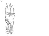
- the proposed method is shown in FIG. It is to grip so as to surround the circumference of the utility pole.
- FIG. 6 shows the grip portion. Since it has enough power to lift the utility pole, the utility pole can be lifted without shaking. Therefore, it is possible to insert (backfill) the utility pole into the hole made in the ground without shaking. Therefore, the number of workers can be reduced.
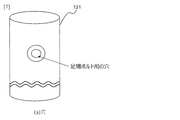
- FIGS. 7 to 10 show that the utility pole 121 has a hole for a scaffolding bolt.
- FIG. 8 shows a rod called a scaffolding bolt 131.
- FIG. 9 shows a drawing in which the scaffolding bolt 131 is inserted into the hole of the utility pole 121 and fixed. As shown in FIG. 9, it is shown that a plurality of scaffolding bolts 131 are fixed to one utility pole 121. The worker puts his foot on this scaffolding bolt 131 and climbs the utility pole 121.
- the present invention provides a utility pole rotating device and a position control method capable of reducing the number of personnel required for adjusting the orientation of the side surface of the utility pole, in addition to reducing the number of personnel for stabilizing the utility pole.
- the purpose is.
- the utility pole rotating device of the present disclosure is provided with a roller that can rotate the utility pole in contact with the utility pole to the grip portion that can prevent the utility pole from shaking.
- the utility pole rotating device is a columnar column that comes into contact with a grip portion that grips the utility pole and the utility pole inside the grip portion, and rotates the utility pole about the longitudinal direction by its own rotation. Equipped with rollers.
- the utility pole is gripped so that the side surface of the utility pole is surrounded by the grip portion and the longitudinal direction of the utility pole is perpendicular to the ground, and a circle attached to the grip portion.
- the columnar roller is brought into contact with the electric pole inside the grip portion, and the electric pole is rotated about the longitudinal direction by the rotation of the roller.
- the utility pole rotation device is provided with a roller that can contact the utility pole and can rotate the utility pole to a grip portion that can prevent the utility pole from swinging, so that the utility pole can be gripped and rotated without the utility pole swinging. Can be made to.
- a roller that can contact the utility pole and can rotate the utility pole to a grip portion that can prevent the utility pole from swinging, so that the utility pole can be gripped and rotated without the utility pole swinging. Can be made to.
- the utility pole is fixed at a place separated from the side surface of the utility pole by a predetermined distance in the radial direction of the utility pole, and the side surface of the utility pole is desired by rotation about the longitudinal direction of the utility pole. It is characterized by being further equipped with a sensor that catches and detects a target on the ground when it is turned.
- the utility pole rotating device may notify the sensor by emitting a sound or an optical signal that the side surface of the utility pole is in a desired orientation.
- the utility pole when the utility pole is rotated, it is detected by catching a target object on the ground that the side surface of the utility pole is in a desired direction, and when the target object is detected.
- the rotation of the utility pole is stopped and the operation is further performed.
- the target object when it is detected, it may be notified by emitting a sound or an optical signal that the side surface of the utility pole is in a desired direction.
- the utility pole rotating device has a sensor, so that the orientation of the side surface of the utility pole can be adjusted more easily.
- a utility pole rotating device and a position control method capable of reducing the number of personnel required for adjusting the direction of the side surface of a utility pole, in addition to reducing the number of personnel for stabilizing the utility pole.
- An example of a conventional utility pole installation method is shown.
- An example of a conventional utility pole installation method is shown.
- An example of a conventional utility pole installation method is shown.
- the usage mode of the grip portion of the utility pole according to the related technology is shown.
- the schematic configuration and usage mode of the grip portion of the utility pole according to the related technology are shown.
- a schematic configuration of a grip portion of a utility pole according to a related technique is shown.
- An example of a hole for a scaffolding bolt of a utility pole is shown.
- An example of how the scaffolding bolt is fixed to the utility pole is shown.
- An example of a schematic configuration of a utility pole to which a scaffolding bolt is fixed is shown.
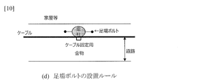
- the installation rules for scaffolding bolts are shown.
- An example of the usage form of the utility pole rotation device which concerns on this invention is shown.
- An example of the usage form of the utility pole rotation device which concerns on this invention is shown.
- An example of the usage form of the utility pole rotation device which concerns on this invention is shown.
- An example of a schematic configuration and a usage pattern of the utility pole rotating device according to the present invention is shown.
- An example of a schematic configuration and a usage pattern of the utility pole rotating device according to the present invention is shown.
- An example of a schematic configuration and a usage pattern of the utility pole rotating device according to the present invention is shown.
- An example of a schematic configuration and a usage pattern of the utility pole rotating device according to the present invention is shown.
- An example of the procedure of the position control method according to the present invention is shown.
- An example of the procedure of the position control method according to the present invention is shown.
- An example of a schematic configuration and a usage pattern of the utility pole rotating device according to the present invention is shown.
- An example of a schematic configuration and a usage pattern of the utility pole rotating device according to the present invention is shown.
- An example of a schematic configuration and a usage pattern of the utility pole rotating device according to the present invention is shown.
- An example of a schematic configuration and a usage pattern of the utility pole rotating device according to the present invention is shown.
- An example of a schematic configuration and a usage pattern of the utility pole rotating device according to the present invention is shown.
- An example of a schematic configuration and a usage pattern of the utility pole rotating device according to the present invention is shown.
- the utility pole rotation device 10 includes a grip portion 11 that grips the utility pole, and a columnar roller 21 that contacts the utility pole 121 inside the grip portion 11 and rotates the utility pole 121 about the longitudinal direction by its own rotation. ..
- the grip portion 11 grips the utility pole 121 so as to surround the side surface of the utility pole 121, and stops the runout of the utility pole 121 when the utility pole 121 is gripped.
- the grip portion 11 has two bendable arms 11a and 11b, and a control unit (not shown) connected to the arms 11a and 11b and controlling the arms 11a and 11b. ..
- the grip portion 11 grips the utility pole 121 by the control unit so that the arms 11a and 11b are perpendicular to the longitudinal axis of the utility pole 121 and surround the side surface of the utility pole 121.
- the roller 21 has a columnar shape and is attached to the grip portion 11 so that the utility pole 121 gripped by the grip portion 11 can come into contact with the inside of the grip portion 11. Further, the roller 21 is attached to the grip portion 11 so that the utility pole 121 can be rotated about the longitudinal direction of the utility pole 121 by its own rotation.
- the number of rollers 21 is three.
- the three rollers 21 are attached to the grip portion 11 so as to surround the utility pole 121 by the three rollers 21 when they come into contact with the utility pole 121.
- the contact of the roller 21 with the utility pole 121 may be performed from the time when the grip portion 11 grips the utility pole 121, or may be performed by moving the roller 21 after gripping the utility pole 121.
- the roller 21 is attached to the grip portion 11 so that the axis in the longitudinal direction of the utility pole 121 and the rotation axis of the roller 21 are parallel when they come into contact with the utility pole 121.
- the grip portion 11 stops contact with the utility pole 121, and by supporting each roller 21, the roller 21 replaces the grip portion 11 with the utility pole 121 to prevent it from shaking. It is desirable to be able to grip while.
- FIGS. 11 to 16 An example of the operation of the utility pole rotating device 10 is shown in FIGS. 11 to 16.
- 11 to 13 show an operation of inserting the utility pole 121 into the hole 110 by the utility pole rotating device 10 provided in the mobile crane 100.
- 14 to 16 show the operation of rotating the utility pole 121 by the grip portion 11.
- FIG. 17 shows a flowchart of the position control method according to the present embodiment.
- the position control method according to the present embodiment includes a gripping step S101 for gripping the utility pole 121 so that the grip portion 11 surrounds the side surface of the utility pole 121 and the longitudinal direction of the utility pole 121 is perpendicular to the ground 105.
- a contact step S102 in which the columnar roller 21 attached to the portion 11 comes into contact with the utility pole 121 inside the grip portion 11 and a rotation step S103 in which the utility pole 121 is rotated about the longitudinal direction by the rotation of the roller 21 are performed.
- steps S101 to S103 will be described in detail.
- FIGS. 11, 12 and 14 show the state of the gripping step S101.
- the utility pole 121 is gripped so that the grip portion 11 surrounds the side surface of the utility pole 121 and the longitudinal direction of the utility pole 121 is perpendicular to the ground 105.
- the grip portion 11 is gripped by the crane wheel 100 so that the arms 11a and 11b are perpendicular to the longitudinal axis of the utility pole 121 and surround the side surface of the utility pole 121.
- the utility pole 121 is erected so that its longitudinal axis is perpendicular to the ground 105. At this point, the utility pole 121 is not inserted into the hole 110.
- the utility pole 121 is gripped by the gripping portion 11 coming into contact with the utility pole 121 without contacting the roller 21 and the utility pole 121.
- FIG. 15 shows the state of the contact step S102.
- the contact step S102 the columnar roller 21 attached to the grip portion 11 is brought into contact with the utility pole 121 inside the grip portion 11.
- the roller 21 is moved and brought into contact with the utility pole 121.
- Step S103 In the rotation step S103, the utility pole 121 is rotated about the longitudinal direction thereof by the rotation of the roller 21.
- FIG. 15 shows a state before rotation
- FIG. 16 shows a state after rotating 90 ° clockwise.
- the utility pole rotating device 10 rotates the side surface of the utility pole 121 to a desired direction by the roller 21, inserts the utility pole 121 to the bottom of the hole 110, and separates the utility pole 121 from the grip portion 11 as shown in FIG.
- the number of personnel required in the invention according to the present embodiment is one of the heavy machine operator 201. Only the guard man (guidance worker) 202 for ensuring the safety of pedestrians. Therefore, by attaching a roller 21 that can come into contact with the utility pole 121 to the grip portion 11 that can hold the utility pole 121, in addition to reducing the number of personnel for the utility pole 121 to hold it, the orientation of the side surface of the utility pole 121 can be adjusted. It is possible to provide a utility pole rotating device and a position control method that can reduce the required number of personnel.
- the number of rollers 21 is not limited to three. The number of rollers 21 changes according to the number of arms of the grip portion 11.
- FIGS. 19 to 24 the utility pole 121 is erected directly above the hole 110 and perpendicular to the ground 105, and shows a state in which the lower bottom surface of the utility pole 121 is about to enter the hole 110. That is, it refers to the state shown in FIG. 19, 23 and 24 are views of the utility pole 121 as viewed from the side. 20 to 22 are views of the utility pole 121 as viewed from above.
- the utility pole rotating device 10 of the present embodiment adds a function of detecting a desired direction of the side surface of the utility pole 121 to the utility pole rotating device 10 of the first embodiment. The function will be described below.
- the utility pole rotating device 10 is fixed at a place separated from the side surface of the utility pole 121 by a predetermined distance in the radial direction of the utility pole 121, and the side surface of the utility pole 121 is oriented in a desired direction by rotation about the longitudinal direction of the utility pole 121.
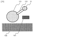
- a sensor 31 that catches and detects a target on the ground 105 is further provided.
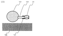
- the scaffolding bolt 131 is vertically fixed to the side surface of the utility pole 121.
- the scaffolding bolt 131 has a scaffolding portion having a length in the radial direction of the utility pole 121 so that a person climbing the utility pole 121 can put his / her foot on it, and a tip portion which is the tip of the scaffolding portion.
- the sensor 31 is fixed to the tip of the scaffolding bolt 131.
- the sensor 31 emits light (L) vertically toward the ground 105 and measures the intensity of the reflected light (R) to determine whether or not the target has been captured.
- the target is line 141.
- the line 141 is on the ground 105 and has a higher reflectance of light (L) than the ground 105.
- the line 141 is located so as to be in the radial direction of the hole 110 and parallel to the road 106 and at least separated from the hole 110 by the length of the scaffolding portion of the scaffolding bolt 131 described above when viewed from directly above the hole 110 into which the utility pole 121 is inserted. It is pulled to pass through (Fig. 20).
- the light (L) emitted by the sensor 31 may be strongly reflected only from the line 141.
- the sensor 31 strongly senses the reflected light (R) when it is directly above the line 141, and detects that it has captured the target line 141.
- the sensor 31 When the sensor 31 catches and detects the target line 141, the sensor 31 notifies the heavy equipment operator 201 that the detection has been made. For example, the sensor 31 may notify by emitting a sound or an optical signal that the side surface of the utility pole 121 is in a desired orientation. In the present embodiment, when the sensor 31 is located directly above the line 141, it is assumed that the side surface of the utility pole 121 is in a desired orientation.
- FIG. 18 shows a flowchart of the position control method according to the present embodiment.
- the position control method according to the present embodiment is based on the position control method (S101 to S103) of the first embodiment, and the ground 105 indicates that the side surface of the utility pole 121 is in a desired direction when the utility pole 121 is rotated.
- a detection step S104 for capturing and detecting the line 141, which is a target object, and a stop step S105 for stopping the rotation of the utility pole 121 when the line 141 is detected are further performed.
- Steps S101 to S103 are the same as those in the first embodiment.
- the operation of step S103 according to the present embodiment and the newly added steps S104 and S105 will be described in detail.
- FIG. 20 shows a state before the utility pole rotating device 10 rotates the utility pole 121.
- FIG. 21 shows how the utility pole rotating device 10 rotates the utility pole 121 so that the sensor 31 comes directly above the line 141 in step S103.
- the intensity of the reflected light (R) measured by the sensor 31 becomes low, and the sensor 31 does not detect the target object.
- the utility pole rotation device 10 continues to rotate the utility pole 121 until it is detected by the sensor 31.
- Step S104 The rotation of the utility pole 121 in step S103 detects that the side surface of the utility pole 121 is in a desired direction by capturing the line 141, which is a target object on the ground 105.
- the side surface of the utility pole 121 is in a desired orientation.
- the sensor 31 strongly senses the reflected light (R) and detects that the target line 141 is captured (FIG. 23).
- the sensor 31 When the sensor 31 catches and detects the target line 141, the sensor 31 notifies the heavy equipment operator 201 that the detection has been made. For example, the sensor 31 may notify by emitting a sound or an optical signal that the side surface of the utility pole 121 is in a desired direction when the line 141, which is a target object, is detected.
- Step S105 The utility pole rotation device 10 stops rotating the utility pole 121 when the sensor 31 detects the target line 141.
- the heavy equipment operator 201 has a distance between the position where the heavy equipment operator 201 operates the heavy equipment and the installation position of the utility pole 121, and the rotation angle of the utility pole 121 is finely adjusted. Even if it cannot be confirmed, the orientation of the utility pole 121 can be accurately and easily known.
- the utility pole rotating device 10 can more easily adjust the orientation of the side surface of the utility pole 121 by having the sensor 31.
- Utility pole rotating device 11 Grip portion 11a, 11b: Arm 21: Roller 31: Sensor 100: Mobile crane 105: Ground 106: Road 110: Hole 121, 122: Utility pole 131: Scaffolding bolt 141: Line 201: Heavy equipment operator 202: Guidance worker
Landscapes
- Engineering & Computer Science (AREA)
- Mechanical Engineering (AREA)
- Automation & Control Theory (AREA)
- Load-Engaging Elements For Cranes (AREA)
- Conveying And Assembling Of Building Elements In Situ (AREA)
- Manipulator (AREA)
Priority Applications (3)
| Application Number | Priority Date | Filing Date | Title |
|---|---|---|---|
| JP2022527269A JP7347669B2 (ja) | 2020-05-25 | 2020-05-25 | 電柱回転装置及び位置制御方法 |
| US17/926,697 US20230192450A1 (en) | 2020-05-25 | 2020-05-25 | Device for rotating utility pole and method for controlling position |
| PCT/JP2020/020500 WO2021240587A1 (ja) | 2020-05-25 | 2020-05-25 | 電柱回転装置及び位置制御方法 |
Applications Claiming Priority (1)
| Application Number | Priority Date | Filing Date | Title |
|---|---|---|---|
| PCT/JP2020/020500 WO2021240587A1 (ja) | 2020-05-25 | 2020-05-25 | 電柱回転装置及び位置制御方法 |
Publications (1)
| Publication Number | Publication Date |
|---|---|
| WO2021240587A1 true WO2021240587A1 (ja) | 2021-12-02 |
Family
ID=78723156
Family Applications (1)
| Application Number | Title | Priority Date | Filing Date |
|---|---|---|---|
| PCT/JP2020/020500 Ceased WO2021240587A1 (ja) | 2020-05-25 | 2020-05-25 | 電柱回転装置及び位置制御方法 |
Country Status (3)
| Country | Link |
|---|---|
| US (1) | US20230192450A1 (https=) |
| JP (1) | JP7347669B2 (https=) |
| WO (1) | WO2021240587A1 (https=) |
Citations (3)
| Publication number | Priority date | Publication date | Assignee | Title |
|---|---|---|---|---|
| JPS59138415A (ja) * | 1982-12-30 | 1984-08-08 | ゲ−・ア−・プフライデラ− ゲ−・エム・ベ・ハ−・ウント コンパニイ カ−・ゲ−・ | 強化プラスチツク製の円錐形中空電柱を製造するための装置 |
| US4652195A (en) * | 1984-01-26 | 1987-03-24 | Mcarthur James R | Casing stabbing and positioning apparatus |
| JP2015061449A (ja) * | 2013-09-19 | 2015-03-30 | 中国電力株式会社 | シートクリップ |
Family Cites Families (8)
| Publication number | Priority date | Publication date | Assignee | Title |
|---|---|---|---|---|
| US1558261A (en) * | 1925-01-20 | 1925-10-20 | Frank W Grady | Pipe elevator |
| US7032678B2 (en) * | 1999-10-01 | 2006-04-25 | Frank's Casing Crew And Rental Tools, Inc. | Horseshoe shaped elevator and method for using same |
| US6554337B2 (en) * | 2000-12-07 | 2003-04-29 | Homayoon Kazerooni | Mechanical grapple for grabbing and holding sacks and bags |
| US6938519B2 (en) * | 2003-07-01 | 2005-09-06 | Harnischfeger Technologies, Inc. | Automatic breakout wrench with floating gripping dies |
| US8632111B2 (en) * | 2003-12-12 | 2014-01-21 | Varco I/P, Inc. | Apparatus and method for facilitating handling pipe |
| US7992909B2 (en) * | 2007-07-12 | 2011-08-09 | Frank's Casing Crew And Rental Tools, Inc. | Single joint elevator with jaws secured by a powered door |
| US10830754B2 (en) * | 2018-09-19 | 2020-11-10 | Osmose Utilities Services, Inc. | Automated profiling of the condition of wood |
| US11624247B2 (en) * | 2019-04-17 | 2023-04-11 | Black Diamond Oilfield Rentals LLC | Elevator grip lifting and rotary slip holding system and methods thereof |
-
2020
- 2020-05-25 WO PCT/JP2020/020500 patent/WO2021240587A1/ja not_active Ceased
- 2020-05-25 US US17/926,697 patent/US20230192450A1/en active Pending
- 2020-05-25 JP JP2022527269A patent/JP7347669B2/ja active Active
Patent Citations (3)
| Publication number | Priority date | Publication date | Assignee | Title |
|---|---|---|---|---|
| JPS59138415A (ja) * | 1982-12-30 | 1984-08-08 | ゲ−・ア−・プフライデラ− ゲ−・エム・ベ・ハ−・ウント コンパニイ カ−・ゲ−・ | 強化プラスチツク製の円錐形中空電柱を製造するための装置 |
| US4652195A (en) * | 1984-01-26 | 1987-03-24 | Mcarthur James R | Casing stabbing and positioning apparatus |
| JP2015061449A (ja) * | 2013-09-19 | 2015-03-30 | 中国電力株式会社 | シートクリップ |
Also Published As
| Publication number | Publication date |
|---|---|
| JP7347669B2 (ja) | 2023-09-20 |
| US20230192450A1 (en) | 2023-06-22 |
| JPWO2021240587A1 (https=) | 2021-12-02 |
Similar Documents
| Publication | Publication Date | Title |
|---|---|---|
| CN101659379B (zh) | 一种吊钩偏摆控制方法、系统及装置 | |
| CN101765558B (zh) | 一种安装设备 | |
| US10669135B2 (en) | Rotary crane and method for rotary crane | |
| WO2015113400A1 (zh) | 钢丝绳摇摆检测装置及起重机械 | |
| US11787667B2 (en) | Lifting assembly and a method for handling a component | |
| CN114572816B (zh) | 叶片吊具的控制方法和系统 | |
| CN104627849A (zh) | 一种用于内天井管道吊装的吊装设备及吊装方法 | |
| WO2021240587A1 (ja) | 電柱回転装置及び位置制御方法 | |
| CN108252224A (zh) | 一种利用双台缆载吊机协同荡移吊装钢梁的方法 | |
| JP2019031340A (ja) | ラフィングジブの組み立て状態確認装置 | |
| JP2020089192A (ja) | 仮支持柱、電柱建替支援装置及び電柱建替方法 | |
| GB2544513A (en) | Controller and method of controlling a load | |
| CN104404888B (zh) | 一种大型空中坡度调整吊装系统及应用 | |
| US10850952B2 (en) | Pipelayer with quick attach counterweights | |
| CN202245860U (zh) | 臂架回转角度的测量装置 | |
| CN117842845B (zh) | 一种预制楼梯吊装系统 | |
| CN219118253U (zh) | 一种建筑桩基缺陷检测设备 | |
| CN103213907A (zh) | 塔式起重机 | |
| JPH0126712Y2 (https=) | ||
| CN105110202A (zh) | 转臂式柱上开关起吊支架 | |
| KR102049397B1 (ko) | 타워 크레인용 안전장치 | |
| CN109607372B (zh) | 一种吊具 | |
| CN223534688U (zh) | 一种稳定高的钢结构箱梁吊装装置 | |
| CN217323091U (zh) | 一种用于塔式起重机的幅度稳定装置 | |
| CN211226086U (zh) | 一种移动式柱上起重器 |
Legal Events
| Date | Code | Title | Description |
|---|---|---|---|
| 121 | Ep: the epo has been informed by wipo that ep was designated in this application |
Ref document number: 20937433 Country of ref document: EP Kind code of ref document: A1 |
|
| ENP | Entry into the national phase |
Ref document number: 2022527269 Country of ref document: JP Kind code of ref document: A |
|
| NENP | Non-entry into the national phase |
Ref country code: DE |
|
| 122 | Ep: pct application non-entry in european phase |
Ref document number: 20937433 Country of ref document: EP Kind code of ref document: A1 |