WO2021240587A1 - 電柱回転装置及び位置制御方法 - Google Patents
電柱回転装置及び位置制御方法 Download PDFInfo
- Publication number
- WO2021240587A1 WO2021240587A1 PCT/JP2020/020500 JP2020020500W WO2021240587A1 WO 2021240587 A1 WO2021240587 A1 WO 2021240587A1 JP 2020020500 W JP2020020500 W JP 2020020500W WO 2021240587 A1 WO2021240587 A1 WO 2021240587A1
- Authority
- WO
- WIPO (PCT)
- Prior art keywords
- utility pole
- utility
- grip portion
- rotating device
- control method
- Prior art date
Links
Images


Classifications
-
- B—PERFORMING OPERATIONS; TRANSPORTING
- B66—HOISTING; LIFTING; HAULING
- B66C—CRANES; LOAD-ENGAGING ELEMENTS OR DEVICES FOR CRANES, CAPSTANS, WINCHES, OR TACKLES
- B66C1/00—Load-engaging elements or devices attached to lifting or lowering gear of cranes or adapted for connection therewith for transmitting lifting forces to articles or groups of articles
- B66C1/10—Load-engaging elements or devices attached to lifting or lowering gear of cranes or adapted for connection therewith for transmitting lifting forces to articles or groups of articles by mechanical means
- B66C1/22—Rigid members, e.g. L-shaped members, with parts engaging the under surface of the loads; Crane hooks
- B66C1/28—Duplicate, e.g. pivoted, members engaging the loads from two sides
-
- B—PERFORMING OPERATIONS; TRANSPORTING
- B66—HOISTING; LIFTING; HAULING
- B66C—CRANES; LOAD-ENGAGING ELEMENTS OR DEVICES FOR CRANES, CAPSTANS, WINCHES, OR TACKLES
- B66C1/00—Load-engaging elements or devices attached to lifting or lowering gear of cranes or adapted for connection therewith for transmitting lifting forces to articles or groups of articles
- B66C1/10—Load-engaging elements or devices attached to lifting or lowering gear of cranes or adapted for connection therewith for transmitting lifting forces to articles or groups of articles by mechanical means
- B66C1/42—Gripping members engaging only the external or internal surfaces of the articles
- B66C1/44—Gripping members engaging only the external or internal surfaces of the articles and applying frictional forces
-
- B—PERFORMING OPERATIONS; TRANSPORTING
- B66—HOISTING; LIFTING; HAULING
- B66C—CRANES; LOAD-ENGAGING ELEMENTS OR DEVICES FOR CRANES, CAPSTANS, WINCHES, OR TACKLES
- B66C1/00—Load-engaging elements or devices attached to lifting or lowering gear of cranes or adapted for connection therewith for transmitting lifting forces to articles or groups of articles
- B66C1/10—Load-engaging elements or devices attached to lifting or lowering gear of cranes or adapted for connection therewith for transmitting lifting forces to articles or groups of articles by mechanical means
- B66C1/42—Gripping members engaging only the external or internal surfaces of the articles
- B66C1/58—Gripping members engaging only the external or internal surfaces of the articles and deforming the articles, e.g. by using gripping members such as tongs or grapples
- B66C1/585—Log grapples
-
- B—PERFORMING OPERATIONS; TRANSPORTING
- B66—HOISTING; LIFTING; HAULING
- B66C—CRANES; LOAD-ENGAGING ELEMENTS OR DEVICES FOR CRANES, CAPSTANS, WINCHES, OR TACKLES
- B66C1/00—Load-engaging elements or devices attached to lifting or lowering gear of cranes or adapted for connection therewith for transmitting lifting forces to articles or groups of articles
- B66C1/68—Load-engaging elements or devices attached to lifting or lowering gear of cranes or adapted for connection therewith for transmitting lifting forces to articles or groups of articles mounted on, or guided by, jibs
-
- B—PERFORMING OPERATIONS; TRANSPORTING
- B66—HOISTING; LIFTING; HAULING
- B66C—CRANES; LOAD-ENGAGING ELEMENTS OR DEVICES FOR CRANES, CAPSTANS, WINCHES, OR TACKLES
- B66C13/00—Other constructional features or details
- B66C13/18—Control systems or devices
- B66C13/46—Position indicators for suspended loads or for crane elements
-
- B—PERFORMING OPERATIONS; TRANSPORTING
- B66—HOISTING; LIFTING; HAULING
- B66C—CRANES; LOAD-ENGAGING ELEMENTS OR DEVICES FOR CRANES, CAPSTANS, WINCHES, OR TACKLES
- B66C2700/00—Cranes
- B66C2700/03—Cranes with arms or jibs; Multiple cranes
- B66C2700/0321—Travelling cranes
- B66C2700/0357—Cranes on road or off-road vehicles, on trailers or towed vehicles; Cranes on wheels or crane-trucks
Definitions
- the present invention relates to a device and a method for rotating a utility pole while holding it.
- Utility poles installed outdoors are used by telecommunications companies to support communication cables, and by electric power companies to support cables for power transmission and distribution.
- FIGS. 1 to 3 show how to erect utility poles.
- a hole 110 is dug in the ground 105 with a mobile crane 100.
- the utility pole 121 is lifted by the crane of the mobile crane 100.
- backfilling is performed in which the utility pole 121 is inserted into the hole 110.
- it is common to use a crane wheel 100 to lift the utility pole 121, move it, and build it.
- Utility poles are columnar, and when the utility poles are hung by a crane, the utility poles naturally swing. Utility poles are heavy because they are composed of concrete and iron. As shown in FIG. 2, if a heavy columnar utility pole 121 is lifted at the center of the utility pole 121 in the longitudinal direction by a crane, it is easy to imagine that the utility pole 121 will shake. A heavy utility pole 121 sways, for example, if a person passes by and hits the person, he / she will be seriously injured. Therefore, a worker holds the end of the utility pole 121, a worker is arranged so that the utility pole 121 does not swing, and a guidance worker 202 is arranged to protect pedestrians and the like.
- the utility pole 121 when the utility pole 121 is hung by a crane, the utility pole 121 swings, so that a worker for steady rest and a guidance worker 202 are required, and the number of workers is large to build the utility pole 121.
- Patent Document 1 a heavy machine that can reduce the number of workers has been proposed (Patent Document 1).
- the points of Patent Document 1 are shown in FIG. Using heavy machinery is the same as in FIGS. 1 to 3. The different point is how to grip the utility pole.
- FIG. 2 since the center of the utility pole is hung with a rope, it starts to swing when the balance of the utility pole is lost.
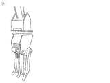
- the proposed method is shown in FIG. It is to grip so as to surround the circumference of the utility pole.
- FIG. 6 shows the grip portion. Since it has enough power to lift the utility pole, the utility pole can be lifted without shaking. Therefore, it is possible to insert (backfill) the utility pole into the hole made in the ground without shaking. Therefore, the number of workers can be reduced.
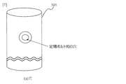
- FIGS. 7 to 10 show that the utility pole 121 has a hole for a scaffolding bolt.
- FIG. 8 shows a rod called a scaffolding bolt 131.
- FIG. 9 shows a drawing in which the scaffolding bolt 131 is inserted into the hole of the utility pole 121 and fixed. As shown in FIG. 9, it is shown that a plurality of scaffolding bolts 131 are fixed to one utility pole 121. The worker puts his foot on this scaffolding bolt 131 and climbs the utility pole 121.
- the present invention provides a utility pole rotating device and a position control method capable of reducing the number of personnel required for adjusting the orientation of the side surface of the utility pole, in addition to reducing the number of personnel for stabilizing the utility pole.
- the purpose is.
- the utility pole rotating device of the present disclosure is provided with a roller that can rotate the utility pole in contact with the utility pole to the grip portion that can prevent the utility pole from shaking.
- the utility pole rotating device is a columnar column that comes into contact with a grip portion that grips the utility pole and the utility pole inside the grip portion, and rotates the utility pole about the longitudinal direction by its own rotation. Equipped with rollers.
- the utility pole is gripped so that the side surface of the utility pole is surrounded by the grip portion and the longitudinal direction of the utility pole is perpendicular to the ground, and a circle attached to the grip portion.
- the columnar roller is brought into contact with the electric pole inside the grip portion, and the electric pole is rotated about the longitudinal direction by the rotation of the roller.
- the utility pole rotation device is provided with a roller that can contact the utility pole and can rotate the utility pole to a grip portion that can prevent the utility pole from swinging, so that the utility pole can be gripped and rotated without the utility pole swinging. Can be made to.
- a roller that can contact the utility pole and can rotate the utility pole to a grip portion that can prevent the utility pole from swinging, so that the utility pole can be gripped and rotated without the utility pole swinging. Can be made to.
- the utility pole is fixed at a place separated from the side surface of the utility pole by a predetermined distance in the radial direction of the utility pole, and the side surface of the utility pole is desired by rotation about the longitudinal direction of the utility pole. It is characterized by being further equipped with a sensor that catches and detects a target on the ground when it is turned.
- the utility pole rotating device may notify the sensor by emitting a sound or an optical signal that the side surface of the utility pole is in a desired orientation.
- the utility pole when the utility pole is rotated, it is detected by catching a target object on the ground that the side surface of the utility pole is in a desired direction, and when the target object is detected.
- the rotation of the utility pole is stopped and the operation is further performed.
- the target object when it is detected, it may be notified by emitting a sound or an optical signal that the side surface of the utility pole is in a desired direction.
- the utility pole rotating device has a sensor, so that the orientation of the side surface of the utility pole can be adjusted more easily.
- a utility pole rotating device and a position control method capable of reducing the number of personnel required for adjusting the direction of the side surface of a utility pole, in addition to reducing the number of personnel for stabilizing the utility pole.
- An example of a conventional utility pole installation method is shown.
- An example of a conventional utility pole installation method is shown.
- An example of a conventional utility pole installation method is shown.
- the usage mode of the grip portion of the utility pole according to the related technology is shown.
- the schematic configuration and usage mode of the grip portion of the utility pole according to the related technology are shown.
- a schematic configuration of a grip portion of a utility pole according to a related technique is shown.
- An example of a hole for a scaffolding bolt of a utility pole is shown.
- An example of how the scaffolding bolt is fixed to the utility pole is shown.
- An example of a schematic configuration of a utility pole to which a scaffolding bolt is fixed is shown.
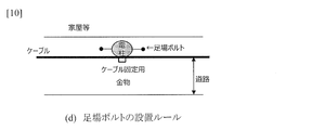
- the installation rules for scaffolding bolts are shown.
- An example of the usage form of the utility pole rotation device which concerns on this invention is shown.
- An example of the usage form of the utility pole rotation device which concerns on this invention is shown.
- An example of the usage form of the utility pole rotation device which concerns on this invention is shown.
- An example of a schematic configuration and a usage pattern of the utility pole rotating device according to the present invention is shown.
- An example of a schematic configuration and a usage pattern of the utility pole rotating device according to the present invention is shown.
- An example of a schematic configuration and a usage pattern of the utility pole rotating device according to the present invention is shown.
- An example of a schematic configuration and a usage pattern of the utility pole rotating device according to the present invention is shown.
- An example of the procedure of the position control method according to the present invention is shown.
- An example of the procedure of the position control method according to the present invention is shown.
- An example of a schematic configuration and a usage pattern of the utility pole rotating device according to the present invention is shown.
- An example of a schematic configuration and a usage pattern of the utility pole rotating device according to the present invention is shown.
- An example of a schematic configuration and a usage pattern of the utility pole rotating device according to the present invention is shown.
- An example of a schematic configuration and a usage pattern of the utility pole rotating device according to the present invention is shown.
- An example of a schematic configuration and a usage pattern of the utility pole rotating device according to the present invention is shown.
- An example of a schematic configuration and a usage pattern of the utility pole rotating device according to the present invention is shown.
- the utility pole rotation device 10 includes a grip portion 11 that grips the utility pole, and a columnar roller 21 that contacts the utility pole 121 inside the grip portion 11 and rotates the utility pole 121 about the longitudinal direction by its own rotation. ..
- the grip portion 11 grips the utility pole 121 so as to surround the side surface of the utility pole 121, and stops the runout of the utility pole 121 when the utility pole 121 is gripped.
- the grip portion 11 has two bendable arms 11a and 11b, and a control unit (not shown) connected to the arms 11a and 11b and controlling the arms 11a and 11b. ..
- the grip portion 11 grips the utility pole 121 by the control unit so that the arms 11a and 11b are perpendicular to the longitudinal axis of the utility pole 121 and surround the side surface of the utility pole 121.
- the roller 21 has a columnar shape and is attached to the grip portion 11 so that the utility pole 121 gripped by the grip portion 11 can come into contact with the inside of the grip portion 11. Further, the roller 21 is attached to the grip portion 11 so that the utility pole 121 can be rotated about the longitudinal direction of the utility pole 121 by its own rotation.
- the number of rollers 21 is three.
- the three rollers 21 are attached to the grip portion 11 so as to surround the utility pole 121 by the three rollers 21 when they come into contact with the utility pole 121.
- the contact of the roller 21 with the utility pole 121 may be performed from the time when the grip portion 11 grips the utility pole 121, or may be performed by moving the roller 21 after gripping the utility pole 121.
- the roller 21 is attached to the grip portion 11 so that the axis in the longitudinal direction of the utility pole 121 and the rotation axis of the roller 21 are parallel when they come into contact with the utility pole 121.
- the grip portion 11 stops contact with the utility pole 121, and by supporting each roller 21, the roller 21 replaces the grip portion 11 with the utility pole 121 to prevent it from shaking. It is desirable to be able to grip while.
- FIGS. 11 to 16 An example of the operation of the utility pole rotating device 10 is shown in FIGS. 11 to 16.
- 11 to 13 show an operation of inserting the utility pole 121 into the hole 110 by the utility pole rotating device 10 provided in the mobile crane 100.
- 14 to 16 show the operation of rotating the utility pole 121 by the grip portion 11.
- FIG. 17 shows a flowchart of the position control method according to the present embodiment.
- the position control method according to the present embodiment includes a gripping step S101 for gripping the utility pole 121 so that the grip portion 11 surrounds the side surface of the utility pole 121 and the longitudinal direction of the utility pole 121 is perpendicular to the ground 105.
- a contact step S102 in which the columnar roller 21 attached to the portion 11 comes into contact with the utility pole 121 inside the grip portion 11 and a rotation step S103 in which the utility pole 121 is rotated about the longitudinal direction by the rotation of the roller 21 are performed.
- steps S101 to S103 will be described in detail.
- FIGS. 11, 12 and 14 show the state of the gripping step S101.
- the utility pole 121 is gripped so that the grip portion 11 surrounds the side surface of the utility pole 121 and the longitudinal direction of the utility pole 121 is perpendicular to the ground 105.
- the grip portion 11 is gripped by the crane wheel 100 so that the arms 11a and 11b are perpendicular to the longitudinal axis of the utility pole 121 and surround the side surface of the utility pole 121.
- the utility pole 121 is erected so that its longitudinal axis is perpendicular to the ground 105. At this point, the utility pole 121 is not inserted into the hole 110.
- the utility pole 121 is gripped by the gripping portion 11 coming into contact with the utility pole 121 without contacting the roller 21 and the utility pole 121.
- FIG. 15 shows the state of the contact step S102.
- the contact step S102 the columnar roller 21 attached to the grip portion 11 is brought into contact with the utility pole 121 inside the grip portion 11.
- the roller 21 is moved and brought into contact with the utility pole 121.
- Step S103 In the rotation step S103, the utility pole 121 is rotated about the longitudinal direction thereof by the rotation of the roller 21.
- FIG. 15 shows a state before rotation
- FIG. 16 shows a state after rotating 90 ° clockwise.
- the utility pole rotating device 10 rotates the side surface of the utility pole 121 to a desired direction by the roller 21, inserts the utility pole 121 to the bottom of the hole 110, and separates the utility pole 121 from the grip portion 11 as shown in FIG.
- the number of personnel required in the invention according to the present embodiment is one of the heavy machine operator 201. Only the guard man (guidance worker) 202 for ensuring the safety of pedestrians. Therefore, by attaching a roller 21 that can come into contact with the utility pole 121 to the grip portion 11 that can hold the utility pole 121, in addition to reducing the number of personnel for the utility pole 121 to hold it, the orientation of the side surface of the utility pole 121 can be adjusted. It is possible to provide a utility pole rotating device and a position control method that can reduce the required number of personnel.
- the number of rollers 21 is not limited to three. The number of rollers 21 changes according to the number of arms of the grip portion 11.
- FIGS. 19 to 24 the utility pole 121 is erected directly above the hole 110 and perpendicular to the ground 105, and shows a state in which the lower bottom surface of the utility pole 121 is about to enter the hole 110. That is, it refers to the state shown in FIG. 19, 23 and 24 are views of the utility pole 121 as viewed from the side. 20 to 22 are views of the utility pole 121 as viewed from above.
- the utility pole rotating device 10 of the present embodiment adds a function of detecting a desired direction of the side surface of the utility pole 121 to the utility pole rotating device 10 of the first embodiment. The function will be described below.
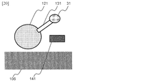
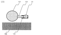
- the utility pole rotating device 10 is fixed at a place separated from the side surface of the utility pole 121 by a predetermined distance in the radial direction of the utility pole 121, and the side surface of the utility pole 121 is oriented in a desired direction by rotation about the longitudinal direction of the utility pole 121.
- a sensor 31 that catches and detects a target on the ground 105 is further provided.
- the scaffolding bolt 131 is vertically fixed to the side surface of the utility pole 121.
- the scaffolding bolt 131 has a scaffolding portion having a length in the radial direction of the utility pole 121 so that a person climbing the utility pole 121 can put his / her foot on it, and a tip portion which is the tip of the scaffolding portion.
- the sensor 31 is fixed to the tip of the scaffolding bolt 131.
- the sensor 31 emits light (L) vertically toward the ground 105 and measures the intensity of the reflected light (R) to determine whether or not the target has been captured.
- the target is line 141.
- the line 141 is on the ground 105 and has a higher reflectance of light (L) than the ground 105.
- the line 141 is located so as to be in the radial direction of the hole 110 and parallel to the road 106 and at least separated from the hole 110 by the length of the scaffolding portion of the scaffolding bolt 131 described above when viewed from directly above the hole 110 into which the utility pole 121 is inserted. It is pulled to pass through (Fig. 20).
- the light (L) emitted by the sensor 31 may be strongly reflected only from the line 141.
- the sensor 31 strongly senses the reflected light (R) when it is directly above the line 141, and detects that it has captured the target line 141.
- the sensor 31 When the sensor 31 catches and detects the target line 141, the sensor 31 notifies the heavy equipment operator 201 that the detection has been made. For example, the sensor 31 may notify by emitting a sound or an optical signal that the side surface of the utility pole 121 is in a desired orientation. In the present embodiment, when the sensor 31 is located directly above the line 141, it is assumed that the side surface of the utility pole 121 is in a desired orientation.
- FIG. 18 shows a flowchart of the position control method according to the present embodiment.
- the position control method according to the present embodiment is based on the position control method (S101 to S103) of the first embodiment, and the ground 105 indicates that the side surface of the utility pole 121 is in a desired direction when the utility pole 121 is rotated.
- a detection step S104 for capturing and detecting the line 141, which is a target object, and a stop step S105 for stopping the rotation of the utility pole 121 when the line 141 is detected are further performed.
- Steps S101 to S103 are the same as those in the first embodiment.
- the operation of step S103 according to the present embodiment and the newly added steps S104 and S105 will be described in detail.
- FIG. 20 shows a state before the utility pole rotating device 10 rotates the utility pole 121.
- FIG. 21 shows how the utility pole rotating device 10 rotates the utility pole 121 so that the sensor 31 comes directly above the line 141 in step S103.
- the intensity of the reflected light (R) measured by the sensor 31 becomes low, and the sensor 31 does not detect the target object.
- the utility pole rotation device 10 continues to rotate the utility pole 121 until it is detected by the sensor 31.
- Step S104 The rotation of the utility pole 121 in step S103 detects that the side surface of the utility pole 121 is in a desired direction by capturing the line 141, which is a target object on the ground 105.
- the side surface of the utility pole 121 is in a desired orientation.
- the sensor 31 strongly senses the reflected light (R) and detects that the target line 141 is captured (FIG. 23).
- the sensor 31 When the sensor 31 catches and detects the target line 141, the sensor 31 notifies the heavy equipment operator 201 that the detection has been made. For example, the sensor 31 may notify by emitting a sound or an optical signal that the side surface of the utility pole 121 is in a desired direction when the line 141, which is a target object, is detected.
- Step S105 The utility pole rotation device 10 stops rotating the utility pole 121 when the sensor 31 detects the target line 141.
- the heavy equipment operator 201 has a distance between the position where the heavy equipment operator 201 operates the heavy equipment and the installation position of the utility pole 121, and the rotation angle of the utility pole 121 is finely adjusted. Even if it cannot be confirmed, the orientation of the utility pole 121 can be accurately and easily known.
- the utility pole rotating device 10 can more easily adjust the orientation of the side surface of the utility pole 121 by having the sensor 31.
- Utility pole rotating device 11 Grip portion 11a, 11b: Arm 21: Roller 31: Sensor 100: Mobile crane 105: Ground 106: Road 110: Hole 121, 122: Utility pole 131: Scaffolding bolt 141: Line 201: Heavy equipment operator 202: Guidance worker
Abstract
本開示では、電柱の振れ止め用の人員及び足場ボルトの向き(電柱の側面の向き)を調整するための人員を同時には削減できないという関連技術の課題を解決するため、電柱の振れ止め用の人員の削減に加えて、電柱の側面の向きの調整に要する人員を減らすことができる電柱回転装置及び位置制御方法を提供することを目的とする。 本開示に係る電柱回転装置は、電柱を把持する把持部と、前記把持部の内側で前記電柱と接触し、自身の回転により前記電柱を長手方向を軸として回転させる円柱状のローラーと、を備える。
Description
本発明は、電柱を把持したまま回転させる装置および方法に関する。
屋外に設置された電柱は、通信会社では通信用ケーブルを支持し、電力会社では送電や配電をするケーブルを支持する形態で使われている。
電柱の使用形態は、電柱を立てて、その電柱にケーブルなどを添架させている。電柱の立てる方法を図1から図3までに示す。図1に示すようにクレーン車100で地面105に穴110を掘る。そして、図2に示すように、電柱121をクレーン車100のクレーンで吊り上げる。最後に、図3で示すように、穴110に電柱121を入れる埋め戻しを行う。電柱121を立てる工事では、クレーン車100を使い電柱121を吊り上げて移動、建て込みをおこなう施工が一般的である。
電柱の構造は、円柱状であることは知られており、その電柱をクレーンで吊るした場合、当然、電柱が振れる。電柱は、コンクリートと鉄から構成されているため、重量が重い。図2に示すように、クレーンで重量のある円柱状の電柱121を電柱121の長手方向の中心で持ち上げれば、電柱121が揺れることは容易に想像がつく。重い電柱121が揺れ、例えば、その近くに人が通行して、その人に当たれば大けがをする。そこで、電柱121の末端を作業員が持ち、電柱121が振れないように作業員を配置し、さらには、歩行者等を守るために誘導作業員202を配置している。
前述したように、クレーンで電柱121を吊る場合、電柱121が振れるため、振れ止め用の作業員及び誘導作業員202が必要となり、電柱121を建てるには、作業員数が多くなる。
そこで、作業員の人数を減らすことができる重機が提案されている(特許文献1)。特許文献1のポイントを図4に示す。重機を使うことは図1から図3までと同じある。異なるポイントは、電柱の把持方法である。図2では、電柱の真ん中をロープで吊るすため、電柱のバランスが崩れると振れだす。一方で、提案されている方法を図5に示す。電柱の円周を囲うようにして把持することである。図6は、把持部を示す。電柱を持ち上げる十分なパワーを兼ね備えているため、電柱は振れることなく、持ち上げることができる。よって、地面に開けた穴に電柱を振れることなく入れること(埋め戻し)ができる。よって、作業員の人数を削減できる。
しかし、電柱には方向があり、その方向を無視して埋め戻すことはできない。電柱の向きを図7から図10までに示す。電柱121には足場ボルト用の穴があることを図7に示す。図8に足場ボルト131と言われている棒を示す。この足場ボルト131を電柱121の穴に入れ、固定した図面を図9に示す。図9に示すように1本の電柱121に複数の足場ボルト131を固定していることを示す。作業員はこの足場ボルト131に足をかけて、電柱121を登っていく。
この足場ボルト設置できる方向にはルールがあり、そのルールを図10に示す。道路に対して足場ボルト、ケーブルが並行になるように設置するルールが課せられている。現在はクレーンで吊った状態で、作業員が手で微調整してあわせている。よって、作業員が手で合わせているため、そのために作業員を準備しなければいけない。
関連技術では、前述したように電柱の振れ止め用の作業員の人員を削減できる。しかし、把持した際に電柱を回転させる機能がないため、電柱を回転させることができず、足場ボルトの向き(電柱の側面の向き)を調整できないという課題があった。
前記課題を解決するために、本発明は、電柱の振れ止め用の人員の削減に加えて、電柱の側面の向きの調整に要する人員を減らすことができる電柱回転装置及び位置制御方法を提供することを目的とする。
上記目的を達成するため、本開示の電柱回転装置は、電柱の振れ止めができる把持部に電柱と接触可能で前記電柱を回転させることができるローラーを付属することとした。
具体的には、本開示に係る電柱回転装置は、電柱を把持する把持部と、前記把持部の内側で前記電柱と接触し、自身の回転により前記電柱を長手方向を軸として回転させる円柱状のローラーと、を備える。
本開示に係る位置制御方法では、把持部により電柱の側面を囲うように、かつ、前記電柱の長手方向が地面と垂直になるように前記電柱を把持することと、前記把持部に付属する円柱状のローラーを前記把持部の内側で前記電柱に接触することと、前記ローラーの回転により前記電柱を長手方向を軸として回転することと、を行う
本開示に係る電柱回転装置は、電柱の振れ止めができる把持部に電柱と接触可能で前記電柱を回転させることができるローラーを付属することにより、電柱が振れることなく、電柱を把持し、回転させることができる。その結果、電柱の振れ止め用の人員の削減に加えて、電柱の側面の向きの調整に要する人員を減らすことができる電柱回転装置及び位置制御方法を提供することができる。
本開示に係る電柱回転装置では、前記電柱の側面から前記電柱の半径方向にあらかじめ定めた距離だけ離れた場所に固定され、前記電柱の長手方向を軸とした回転により前記電柱の側面が所望の向きになったことを地面にある目標物を捉えて検知するセンサーをさらに備えることを特徴とする。
例えば、本開示に係る電柱回転装置は、前記センサーが、前記電柱の側面が所望の向きになったことを音又は光信号を発することにより知らせてもよい。
本開示に係る位置制御方法では、前記電柱を回転するときに、前記電柱の側面が所望の向きになったことを地面にある目標物を捉えて検知することと、前記目標物を検知したときに、前記電柱を回転することを停止することと、をさらに行うことを特徴とする。
例えば、本開示に係る位置制御方法は、前記目標物を検知したときに、前記電柱の側面が所望の向きになったことを音又は光信号を発することにより知らせてもよい。
本電柱回転装置は、センサーを有することにより、より容易に電柱の側面の向きを調整することができる。
なお、上記各発明は、可能な限り組み合わせることができる。
本開示によれば、電柱の振れ止め用の人員の削減に加えて、電柱の側面の向きの調整に要する人員を減らすことができる電柱回転装置及び位置制御方法を提供することができる。
以下、本開示の実施形態について、図面を参照しながら詳細に説明する。なお、本発明は、以下に示す実施形態に限定されるものではない。これらの実施の例は例示に過ぎず、本開示は当業者の知識に基づいて種々の変更、改良を施した形態で実施することができる。なお、本明細書及び図面において符号が同じ構成要素は、相互に同一のものを示すものとする。
(実施形態1)
本実施形態に係る電柱回転装置の一例を図14から図16までに示す。電柱回転装置10は、電柱を把持する把持部11と、把持部11の内側で電柱121と接触し、自身の回転により電柱121を長手方向を軸として回転させる円柱状のローラー21と、を備える。
本実施形態に係る電柱回転装置の一例を図14から図16までに示す。電柱回転装置10は、電柱を把持する把持部11と、把持部11の内側で電柱121と接触し、自身の回転により電柱121を長手方向を軸として回転させる円柱状のローラー21と、を備える。
以下、本実施形態に係る電柱回転装置10の構成と動作について図11から図16までを用いて具体的に示す。図14から図16までは、電柱回転装置10の具体的構成を示す。把持部11は、電柱121の側面を囲うように電柱121を把持し、把持した際の電柱121の振れを止める。本実施形態においては、把持部11は、折れ曲がり可能な2本のアーム11a及び11bと、アーム11a及び11bに接続し、かつ、アーム11a及び11bを制御する制御部(不図示)と、を有する。把持部11は、制御部により、アーム11a及び11bが電柱121の長手方向の軸に垂直になるよう、かつ、電柱121の側面を囲うように電柱121を把持する。
ローラー21は、円柱状の形状であり、把持部11に把持された電柱121と把持部11の内側で接触することができるように把持部11に付属する。また、ローラー21は、自身の回転で、電柱121を電柱121の長手方向を軸として回転させることができるように把持部11に付属する。
本実施形態においては、図14に示すように、ローラー21は、3つとする。3つのローラー21は、電柱121と接触した際に、3つのローラー21により電柱121を囲えるように把持部11に付属する。ローラー21の電柱121への接触は、把持部11が電柱121を把持した時からしてもよいし、把持した後にローラー21の移動によりしてもよい。また、ローラー21は、電柱121と接触した際に、電柱121の長手方向の軸とローラー21の回転軸が平行となるよう把持部11に付属する。
3つのローラー21が電柱121に接触した際に、把持部11が電柱121との接触をやめ、各ローラー21を支えることで、ローラー21が把持部11に代わって電柱121をその振れ止めを行いながら把持できることが望ましい。
電柱回転装置10の動作の一例を図11から図16までに示す。図11から図13までは、クレーン車100に備えられた電柱回転装置10により、電柱121を穴110に入れる動作を示す。また、図14から図16は、把持部11により電柱121を回転させる動作を示す。
本実施形態に係る位置制御方法のフローチャートを図17に示す。本実施形態に係る位置制御方法は、把持部11により電柱121の側面を囲うように、かつ、電柱121の長手方向が地面105と垂直になるように電柱121を把持する把持ステップS101と、把持部11に付属する円柱状のローラー21を把持部11の内側で電柱121に接触する接触ステップS102と、ローラー21の回転により電柱121を長手方向を軸として回転する回転ステップS103と、を行う。以下、ステップS101からS103までを詳細に説明する。
(ステップS101)
図11、12及び14に把持ステップS101の様子を示す。図11及び12に示すように、把持ステップにおいては、把持部11が電柱121の側面を囲うように、かつ、電柱121の長手方向が地面105と垂直になるように電柱121を把持する。本実施形態においては、把持部11は、アーム11a及び11bが電柱121の長手方向の軸に対して垂直となるよう、かつ電柱121の側面を囲うように電柱を把持しながら、クレーン車100により電柱121をその長手方向の軸が地面105と垂直になるように立てる。この時点では、電柱121を穴110に入れない。また、図14に示すように、把持ステップS101においては、ローラー21と電柱121は接触せずに、把持部11が電柱121と接触することにより、電柱121を把持する。
図11、12及び14に把持ステップS101の様子を示す。図11及び12に示すように、把持ステップにおいては、把持部11が電柱121の側面を囲うように、かつ、電柱121の長手方向が地面105と垂直になるように電柱121を把持する。本実施形態においては、把持部11は、アーム11a及び11bが電柱121の長手方向の軸に対して垂直となるよう、かつ電柱121の側面を囲うように電柱を把持しながら、クレーン車100により電柱121をその長手方向の軸が地面105と垂直になるように立てる。この時点では、電柱121を穴110に入れない。また、図14に示すように、把持ステップS101においては、ローラー21と電柱121は接触せずに、把持部11が電柱121と接触することにより、電柱121を把持する。
(ステップS102)
図15に接触ステップS102の様子を示す。接触ステップS102においては、把持部11に付属する円柱状のローラー21を把持部11の内側で電柱121に接触させる。本実施形態においては、ローラー21を移動させ、電柱121に接触させる。
図15に接触ステップS102の様子を示す。接触ステップS102においては、把持部11に付属する円柱状のローラー21を把持部11の内側で電柱121に接触させる。本実施形態においては、ローラー21を移動させ、電柱121に接触させる。
(ステップS103)
回転ステップS103においては、ローラー21の回転により電柱121をその長手方向を軸として回転させる。図15には回転前の様子、図16には、時計回りに90°回転させた後の様子を示す。このように把持部11の先端に複数のローラー21を適用することで、電柱121を円周方向に回転することができる。
回転ステップS103においては、ローラー21の回転により電柱121をその長手方向を軸として回転させる。図15には回転前の様子、図16には、時計回りに90°回転させた後の様子を示す。このように把持部11の先端に複数のローラー21を適用することで、電柱121を円周方向に回転することができる。
電柱回転装置10は、ローラー21で電柱121の側面を所望の向きまで回転した後、穴110の底まで電柱121を入れ、図13に示すように把持部11から電柱121を離す。
以上説明したように、電柱121の振れ止め及び電柱121の側面の向きの調整は電柱回転装置10により可能なため、本実施形態に係る発明において必要な人員は、重機操作者201の1名と歩行者の安全を確保するためのガードマン(誘導作業員)202のみとなる。したがって、電柱121の振れ止めができる把持部11に電柱121と接触可能なローラー21が付属することによって、電柱121の振れ止め用の人員の削減に加えて、電柱121の側面の向きの調整に要する人員を減らすことができる電柱回転装置及び位置制御方法を提供することができる。なお、ローラー21の数は、3に限定されない。把持部11のアームの数に応じてローラー21の数は変化する。
(実施形態2)
以下、本実施形態に係る電柱回転装置10の構成と動作について図18から図24を用いて具体的に示す。図19から図24においては、電柱121は、穴110の真上で地面105に垂直に立てられており、電柱121の下底面が穴110に入る寸前の状態を示す。つまり、図12に示す状態を指す。図19、図23及び図24は、電柱121を横から見た図である。図20から図22までは、電柱121を上から見た図である。本実施形態の電柱回転装置10は、実施形態1の電柱回転装置10に電柱121の側面の所望の向きを検出する機能を追加する。以下で、当該機能を説明する。
以下、本実施形態に係る電柱回転装置10の構成と動作について図18から図24を用いて具体的に示す。図19から図24においては、電柱121は、穴110の真上で地面105に垂直に立てられており、電柱121の下底面が穴110に入る寸前の状態を示す。つまり、図12に示す状態を指す。図19、図23及び図24は、電柱121を横から見た図である。図20から図22までは、電柱121を上から見た図である。本実施形態の電柱回転装置10は、実施形態1の電柱回転装置10に電柱121の側面の所望の向きを検出する機能を追加する。以下で、当該機能を説明する。
電柱回転装置10は、電柱121の側面から電柱121の半径方向にあらかじめ定めた距離だけ離れた場所に固定され、電柱121の長手方向を軸とした回転により電柱121の側面が所望の向きになったことを地面105にある目標物を捉えて検知するセンサー31をさらに備える。
本実施形態においては、図19に示すように、足場ボルト131が電柱121の側面に垂直に固定されているとする。足場ボルト131は、電柱121を登る人が足をかけることができる程度の長さを電柱121の半径方向に持つ足場部分と、その足場部分の先端である先端部を持つ。センサー31は、足場ボルト131の先端部に固定される。
センサー31は、図23に示すように、地面105に向かって垂直に光(L)を発し、その反射光(R)の強度を測定することにより目標物を捉えたか否かを判断する。本実施形態においては、目標物をライン141とする。ライン141は、地面105上にあり、地面105よりも光(L)の反射率が高い。ライン141は、電柱121を入れる穴110の真上から見て、穴110の半径方向かつ道路106に並行するようにかつ少なくとも穴110から前述した足場ボルト131の足場部分の長さだけ離れた場所を通るように引かれる(図20)。センサー31が発する光(L)は、ライン141からのみ強く反射されるとしてもよい。センサー31は、図22に示すように、自身がライン141の真上にある場合に、反射光(R)を強く感知し、目標物であるライン141を捉えたことを検知する。
センサー31は、目標物であるライン141を捉えて検知した際に、重機操作者201に検知したことを通知する。例えば、センサー31は、電柱121の側面が所望の向きになったことを音又は光信号を発することにより知らせてもよい。本実施形態においては、センサー31がライン141の真上に位置する場合に、電柱121の側面が所望の向きになったこととする。
本実施形態に係る位置制御方法のフローチャートを図18に示す。本実施形態に係る位置制御方法は、実施形態1の位置制御方法(S101からS103まで)をベースとし、電柱121を回転するときに、電柱121の側面が所望の向きになったことを地面105にある目標物であるライン141を捉えて検知する検知ステップS104と、ライン141を検知したときに、電柱121を回転することを停止する停止ステップS105と、をさらに行う。ステップS101からS103までは実施形態1と同様とする。以下、本実施形態に係るステップS103並びに新たに追加するステップS104及びS105の動作を詳細に説明する。
(ステップS103)
電柱回転装置10が電柱121を回転させる前の状態を図20に示す。ステップS103において、センサー31がライン141の真上に来るように電柱回転装置10が電柱121を回転させる様子を図21に示す。センサー31は、自身がライン141の真上にない場合には、自身が計測する反射光(R)の強度が低くなり、目標物の検知をしない。電柱回転装置10は、センサー31による検知があるまでは、電柱121を回転させ続ける。
電柱回転装置10が電柱121を回転させる前の状態を図20に示す。ステップS103において、センサー31がライン141の真上に来るように電柱回転装置10が電柱121を回転させる様子を図21に示す。センサー31は、自身がライン141の真上にない場合には、自身が計測する反射光(R)の強度が低くなり、目標物の検知をしない。電柱回転装置10は、センサー31による検知があるまでは、電柱121を回転させ続ける。
(ステップS104)
ステップS103における電柱121の回転により、電柱121の側面が所望の向きになったことを地面105にある目標物であるライン141を捉えて検知する。本実施形態においては、前述したように、センサー31がライン141の真上に位置する場合を、電柱121の側面が所望の向きであるとする。センサー31は、自身がライン141の真上にある場合(図22)に、反射光(R)を強く感知し、目標物であるライン141を捉えたことを検知する(図23)。
ステップS103における電柱121の回転により、電柱121の側面が所望の向きになったことを地面105にある目標物であるライン141を捉えて検知する。本実施形態においては、前述したように、センサー31がライン141の真上に位置する場合を、電柱121の側面が所望の向きであるとする。センサー31は、自身がライン141の真上にある場合(図22)に、反射光(R)を強く感知し、目標物であるライン141を捉えたことを検知する(図23)。
センサー31は、目標物であるライン141を捉えて検知した際に、重機操作者201に検知したことを通知する。例えば、センサー31は、目標物であるライン141を検知したときに、電柱121の側面が所望の向きになったことを音又は光信号を発することにより知らせてもよい。
(ステップS105)
電柱回転装置10は、センサー31が目標物であるライン141を検知したときに、電柱121を回転することを停止する。
電柱回転装置10は、センサー31が目標物であるライン141を検知したときに、電柱121を回転することを停止する。
本実施形態に係る発明により、図24に示すように、重機操作者201は、重機操作者201が重機を操作する位置と電柱121の設置位置との距離があり、電柱121の回転角度を細かく確認できない場合においても、電柱121の向きを正確かつ容易に知ることができる。
以上説明したように、電柱回転装置10は、センサー31を有することにより、より容易に電柱121の側面の向きを調整することができる。
なお、上記各発明は、可能な限り組み合わせることができる。
10:電柱回転装置
11:把持部
11a、11b:アーム
21:ローラー
31:センサー
100:クレーン車
105:地面
106:道路
110:穴
121、122:電柱
131:足場ボルト
141:ライン
201:重機操作者
202:誘導作業員
11:把持部
11a、11b:アーム
21:ローラー
31:センサー
100:クレーン車
105:地面
106:道路
110:穴
121、122:電柱
131:足場ボルト
141:ライン
201:重機操作者
202:誘導作業員
Claims (6)
- 電柱を把持する把持部と、
前記把持部の内側で前記電柱と接触し、自身の回転により前記電柱を長手方向を軸として回転させる円柱状のローラーと、
を備える電柱回転装置。 - 前記電柱の側面から前記電柱の半径方向にあらかじめ定めた距離だけ離れた場所に固定され、前記電柱の長手方向を軸とした回転により前記電柱の側面が所望の向きになったことを地面にある目標物を捉えて検知するセンサーをさらに備える
ことを特徴とする請求項1に記載の電柱回転装置。 - 前記センサーは、前記電柱の側面が所望の向きになったことを音又は光信号を発することにより知らせる
ことを特徴とする請求項2に記載の電柱回転装置。 - 把持部により電柱の側面を囲うように、かつ、前記電柱の長手方向が地面と垂直になるように前記電柱を把持することと、
前記把持部に付属する円柱状のローラーを前記把持部の内側で前記電柱に接触することと、
前記ローラーの回転により前記電柱を長手方向を軸として回転することと、
を行う位置制御方法。 - 前記電柱を回転するときに、
前記電柱の側面が所望の向きになったことを地面にある目標物を捉えて検知することと、
前記目標物を検知したときに、前記電柱を回転することを停止することと、
をさらに行うことを特徴とする請求項4に記載の位置制御方法。 - 前記目標物を検知したときに、前記電柱の側面が所望の向きになったことを音又は光信号を発することにより知らせる
ことを特徴とする請求項5に記載の位置制御方法。
Priority Applications (3)
| Application Number | Priority Date | Filing Date | Title |
|---|---|---|---|
| US17/926,697 US20230192450A1 (en) | 2020-05-25 | 2020-05-25 | Device for rotating utility pole and method for controlling position |
| PCT/JP2020/020500 WO2021240587A1 (ja) | 2020-05-25 | 2020-05-25 | 電柱回転装置及び位置制御方法 |
| JP2022527269A JP7347669B2 (ja) | 2020-05-25 | 2020-05-25 | 電柱回転装置及び位置制御方法 |
Applications Claiming Priority (1)
| Application Number | Priority Date | Filing Date | Title |
|---|---|---|---|
| PCT/JP2020/020500 WO2021240587A1 (ja) | 2020-05-25 | 2020-05-25 | 電柱回転装置及び位置制御方法 |
Publications (1)
| Publication Number | Publication Date |
|---|---|
| WO2021240587A1 true WO2021240587A1 (ja) | 2021-12-02 |
Family
ID=78723156
Family Applications (1)
| Application Number | Title | Priority Date | Filing Date |
|---|---|---|---|
| PCT/JP2020/020500 WO2021240587A1 (ja) | 2020-05-25 | 2020-05-25 | 電柱回転装置及び位置制御方法 |
Country Status (3)
| Country | Link |
|---|---|
| US (1) | US20230192450A1 (ja) |
| JP (1) | JP7347669B2 (ja) |
| WO (1) | WO2021240587A1 (ja) |
Citations (3)
| Publication number | Priority date | Publication date | Assignee | Title |
|---|---|---|---|---|
| JPS59138415A (ja) * | 1982-12-30 | 1984-08-08 | ゲ−・ア−・プフライデラ− ゲ−・エム・ベ・ハ−・ウント コンパニイ カ−・ゲ−・ | 強化プラスチツク製の円錐形中空電柱を製造するための装置 |
| US4652195A (en) * | 1984-01-26 | 1987-03-24 | Mcarthur James R | Casing stabbing and positioning apparatus |
| JP2015061449A (ja) * | 2013-09-19 | 2015-03-30 | 中国電力株式会社 | シートクリップ |
-
2020
- 2020-05-25 WO PCT/JP2020/020500 patent/WO2021240587A1/ja active Application Filing
- 2020-05-25 JP JP2022527269A patent/JP7347669B2/ja active Active
- 2020-05-25 US US17/926,697 patent/US20230192450A1/en active Pending
Patent Citations (3)
| Publication number | Priority date | Publication date | Assignee | Title |
|---|---|---|---|---|
| JPS59138415A (ja) * | 1982-12-30 | 1984-08-08 | ゲ−・ア−・プフライデラ− ゲ−・エム・ベ・ハ−・ウント コンパニイ カ−・ゲ−・ | 強化プラスチツク製の円錐形中空電柱を製造するための装置 |
| US4652195A (en) * | 1984-01-26 | 1987-03-24 | Mcarthur James R | Casing stabbing and positioning apparatus |
| JP2015061449A (ja) * | 2013-09-19 | 2015-03-30 | 中国電力株式会社 | シートクリップ |
Also Published As
| Publication number | Publication date |
|---|---|
| US20230192450A1 (en) | 2023-06-22 |
| JP7347669B2 (ja) | 2023-09-20 |
| JPWO2021240587A1 (ja) | 2021-12-02 |
Similar Documents
| Publication | Publication Date | Title |
|---|---|---|
| CN101659379B (zh) | 一种吊钩偏摆控制方法、系统及装置 | |
| CN101765558B (zh) | 一种安装设备 | |
| US10472214B2 (en) | Crane and method for monitoring the overload protection of such a crane | |
| US10597266B2 (en) | Crane and method for monitoring the overload protection of such a crane | |
| US10669135B2 (en) | Rotary crane and method for rotary crane | |
| CA2554838A1 (en) | Boom lift vehicle and method of controlling lifting functions | |
| WO2015113400A1 (zh) | 钢丝绳摇摆检测装置及起重机械 | |
| WO2021240587A1 (ja) | 電柱回転装置及び位置制御方法 | |
| CN103588095A (zh) | 摆角测量装置及起重机械 | |
| JP6619825B2 (ja) | 水平関節プラットフォームアームアセンブリ | |
| JP2019031340A (ja) | ラフィングジブの組み立て状態確認装置 | |
| US11787667B2 (en) | Lifting assembly and a method for handling a component | |
| CN219118253U (zh) | 一种建筑桩基缺陷检测设备 | |
| CN203624858U (zh) | 摆角测量装置及起重机械 | |
| GB2544513A (en) | Controller and method of controlling a load | |
| JP2020089192A (ja) | 仮支持柱、電柱建替支援装置及び電柱建替方法 | |
| KR102049397B1 (ko) | 타워 크레인용 안전장치 | |
| JPH0126712Y2 (ja) | ||
| CN109607372B (zh) | 一种吊具 | |
| KR20180105784A (ko) | 크레인 점검 장치 및 방법 | |
| WO2023085388A1 (ja) | クレーンの振れ止め装置およびこれを備えたクレーン | |
| CN211226086U (zh) | 一种移动式柱上起重器 | |
| CN112013827B (zh) | 钢绞线液压提升机垂直度检测装置及检测方法 | |
| JPS5852667Y2 (ja) | 誘導電気機器の起立装置 | |
| JPH11182054A (ja) | 移動式懸架支柱 |
Legal Events
| Date | Code | Title | Description |
|---|---|---|---|
| 121 | Ep: the epo has been informed by wipo that ep was designated in this application |
Ref document number: 20937433 Country of ref document: EP Kind code of ref document: A1 |
|
| ENP | Entry into the national phase |
Ref document number: 2022527269 Country of ref document: JP Kind code of ref document: A |
|
| NENP | Non-entry into the national phase |
Ref country code: DE |
|
| 122 | Ep: pct application non-entry in european phase |
Ref document number: 20937433 Country of ref document: EP Kind code of ref document: A1 |