WO2021235552A1 - 乗物用シート及び乗物用シートの製造方法 - Google Patents
乗物用シート及び乗物用シートの製造方法 Download PDFInfo
- Publication number
- WO2021235552A1 WO2021235552A1 PCT/JP2021/019457 JP2021019457W WO2021235552A1 WO 2021235552 A1 WO2021235552 A1 WO 2021235552A1 JP 2021019457 W JP2021019457 W JP 2021019457W WO 2021235552 A1 WO2021235552 A1 WO 2021235552A1
- Authority
- WO
- WIPO (PCT)
- Prior art keywords
- seat
- seat back
- base
- vehicle seat
- drive device
- Prior art date
- Legal status (The legal status is an assumption and is not a legal conclusion. Google has not performed a legal analysis and makes no representation as to the accuracy of the status listed.)
- Ceased
Links
Images








Classifications
-
- B—PERFORMING OPERATIONS; TRANSPORTING
- B60—VEHICLES IN GENERAL
- B60N—SEATS SPECIALLY ADAPTED FOR VEHICLES; VEHICLE PASSENGER ACCOMMODATION NOT OTHERWISE PROVIDED FOR
- B60N2/00—Seats specially adapted for vehicles; Arrangement or mounting of seats in vehicles
- B60N2/24—Seats specially adapted for vehicles; Arrangement or mounting of seats in vehicles for particular purposes or particular vehicles
- B60N2/32—Seats specially adapted for vehicles; Arrangement or mounting of seats in vehicles for particular purposes or particular vehicles convertible for other use
- B60N2/36—Seats specially adapted for vehicles; Arrangement or mounting of seats in vehicles for particular purposes or particular vehicles convertible for other use into a loading platform
-
- B—PERFORMING OPERATIONS; TRANSPORTING
- B60—VEHICLES IN GENERAL
- B60N—SEATS SPECIALLY ADAPTED FOR VEHICLES; VEHICLE PASSENGER ACCOMMODATION NOT OTHERWISE PROVIDED FOR
- B60N2/00—Seats specially adapted for vehicles; Arrangement or mounting of seats in vehicles
- B60N2/02—Seats specially adapted for vehicles; Arrangement or mounting of seats in vehicles the seat or part thereof being movable, e.g. adjustable
- B60N2/20—Seats specially adapted for vehicles; Arrangement or mounting of seats in vehicles the seat or part thereof being movable, e.g. adjustable the back-rest being tiltable, e.g. to permit easy access
-
- A—HUMAN NECESSITIES
- A47—FURNITURE; DOMESTIC ARTICLES OR APPLIANCES; COFFEE MILLS; SPICE MILLS; SUCTION CLEANERS IN GENERAL
- A47C—CHAIRS; SOFAS; BEDS
- A47C1/00—Chairs adapted for special purposes
- A47C1/02—Reclining or easy chairs
- A47C1/022—Reclining or easy chairs having independently-adjustable supporting parts
- A47C1/024—Reclining or easy chairs having independently-adjustable supporting parts the parts, being the back-rest, or the back-rest and seat unit, having adjustable inclination
-
- A—HUMAN NECESSITIES
- A47—FURNITURE; DOMESTIC ARTICLES OR APPLIANCES; COFFEE MILLS; SPICE MILLS; SUCTION CLEANERS IN GENERAL
- A47C—CHAIRS; SOFAS; BEDS
- A47C7/00—Parts, details, or accessories of chairs or stools
- A47C7/36—Supports for the head or the back
- A47C7/40—Supports for the head or the back for the back
-
- B—PERFORMING OPERATIONS; TRANSPORTING
- B60—VEHICLES IN GENERAL
- B60N—SEATS SPECIALLY ADAPTED FOR VEHICLES; VEHICLE PASSENGER ACCOMMODATION NOT OTHERWISE PROVIDED FOR
- B60N2/00—Seats specially adapted for vehicles; Arrangement or mounting of seats in vehicles
- B60N2/002—Seats provided with an occupancy detection means mounted therein or thereon
- B60N2/0021—Seats provided with an occupancy detection means mounted therein or thereon characterised by the type of sensor or measurement
- B60N2/003—Seats provided with an occupancy detection means mounted therein or thereon characterised by the type of sensor or measurement characterised by the sensor mounting location in or on the seat
- B60N2/0033—Seats provided with an occupancy detection means mounted therein or thereon characterised by the type of sensor or measurement characterised by the sensor mounting location in or on the seat mounted on or in the foam cushion
-
- B—PERFORMING OPERATIONS; TRANSPORTING
- B60—VEHICLES IN GENERAL
- B60N—SEATS SPECIALLY ADAPTED FOR VEHICLES; VEHICLE PASSENGER ACCOMMODATION NOT OTHERWISE PROVIDED FOR
- B60N2/00—Seats specially adapted for vehicles; Arrangement or mounting of seats in vehicles
- B60N2/02—Seats specially adapted for vehicles; Arrangement or mounting of seats in vehicles the seat or part thereof being movable, e.g. adjustable
- B60N2/0224—Non-manual adjustments, e.g. with electrical operation
- B60N2/02246—Electric motors therefor
- B60N2/02253—Electric motors therefor characterised by the transmission between the electric motor and the seat or seat parts
-
- B—PERFORMING OPERATIONS; TRANSPORTING
- B60—VEHICLES IN GENERAL
- B60N—SEATS SPECIALLY ADAPTED FOR VEHICLES; VEHICLE PASSENGER ACCOMMODATION NOT OTHERWISE PROVIDED FOR
- B60N2/00—Seats specially adapted for vehicles; Arrangement or mounting of seats in vehicles
- B60N2/24—Seats specially adapted for vehicles; Arrangement or mounting of seats in vehicles for particular purposes or particular vehicles
- B60N2/30—Non-dismountable or dismountable seats storable in a non-use position, e.g. foldable spare seats
- B60N2/3002—Non-dismountable or dismountable seats storable in a non-use position, e.g. foldable spare seats back-rest movements
- B60N2/3004—Non-dismountable or dismountable seats storable in a non-use position, e.g. foldable spare seats back-rest movements by rotation only
- B60N2/3009—Non-dismountable or dismountable seats storable in a non-use position, e.g. foldable spare seats back-rest movements by rotation only about transversal axis
- B60N2/3013—Non-dismountable or dismountable seats storable in a non-use position, e.g. foldable spare seats back-rest movements by rotation only about transversal axis the back-rest being hinged on the vehicle frame
-
- B—PERFORMING OPERATIONS; TRANSPORTING
- B60—VEHICLES IN GENERAL
- B60N—SEATS SPECIALLY ADAPTED FOR VEHICLES; VEHICLE PASSENGER ACCOMMODATION NOT OTHERWISE PROVIDED FOR
- B60N2/00—Seats specially adapted for vehicles; Arrangement or mounting of seats in vehicles
- B60N2/24—Seats specially adapted for vehicles; Arrangement or mounting of seats in vehicles for particular purposes or particular vehicles
- B60N2/30—Non-dismountable or dismountable seats storable in a non-use position, e.g. foldable spare seats
- B60N2/3038—Cushion movements
- B60N2/3063—Cushion movements by composed movement
- B60N2/3065—Cushion movements by composed movement in a longitudinal-vertical plane
-
- B—PERFORMING OPERATIONS; TRANSPORTING
- B60—VEHICLES IN GENERAL
- B60N—SEATS SPECIALLY ADAPTED FOR VEHICLES; VEHICLE PASSENGER ACCOMMODATION NOT OTHERWISE PROVIDED FOR
- B60N2/00—Seats specially adapted for vehicles; Arrangement or mounting of seats in vehicles
- B60N2/24—Seats specially adapted for vehicles; Arrangement or mounting of seats in vehicles for particular purposes or particular vehicles
- B60N2/30—Non-dismountable or dismountable seats storable in a non-use position, e.g. foldable spare seats
- B60N2/3088—Non-dismountable or dismountable seats storable in a non-use position, e.g. foldable spare seats characterised by the mechanical link
- B60N2/309—Non-dismountable or dismountable seats storable in a non-use position, e.g. foldable spare seats characterised by the mechanical link rods
-
- B—PERFORMING OPERATIONS; TRANSPORTING
- B60—VEHICLES IN GENERAL
- B60N—SEATS SPECIALLY ADAPTED FOR VEHICLES; VEHICLE PASSENGER ACCOMMODATION NOT OTHERWISE PROVIDED FOR
- B60N2/00—Seats specially adapted for vehicles; Arrangement or mounting of seats in vehicles
- B60N2/24—Seats specially adapted for vehicles; Arrangement or mounting of seats in vehicles for particular purposes or particular vehicles
- B60N2/32—Seats specially adapted for vehicles; Arrangement or mounting of seats in vehicles for particular purposes or particular vehicles convertible for other use
- B60N2/36—Seats specially adapted for vehicles; Arrangement or mounting of seats in vehicles for particular purposes or particular vehicles convertible for other use into a loading platform
- B60N2/366—Seats specially adapted for vehicles; Arrangement or mounting of seats in vehicles for particular purposes or particular vehicles convertible for other use into a loading platform characterised by the locking device
-
- B—PERFORMING OPERATIONS; TRANSPORTING
- B60—VEHICLES IN GENERAL
- B60N—SEATS SPECIALLY ADAPTED FOR VEHICLES; VEHICLE PASSENGER ACCOMMODATION NOT OTHERWISE PROVIDED FOR
- B60N2/00—Seats specially adapted for vehicles; Arrangement or mounting of seats in vehicles
- B60N2/70—Upholstery springs ; Upholstery
- B60N2/72—Attachment or adjustment thereof
-
- B—PERFORMING OPERATIONS; TRANSPORTING
- B60—VEHICLES IN GENERAL
- B60N—SEATS SPECIALLY ADAPTED FOR VEHICLES; VEHICLE PASSENGER ACCOMMODATION NOT OTHERWISE PROVIDED FOR
- B60N2/00—Seats specially adapted for vehicles; Arrangement or mounting of seats in vehicles
- B60N2/002—Seats provided with an occupancy detection means mounted therein or thereon
- B60N2/0021—Seats provided with an occupancy detection means mounted therein or thereon characterised by the type of sensor or measurement
- B60N2/003—Seats provided with an occupancy detection means mounted therein or thereon characterised by the type of sensor or measurement characterised by the sensor mounting location in or on the seat
- B60N2/0031—Seats provided with an occupancy detection means mounted therein or thereon characterised by the type of sensor or measurement characterised by the sensor mounting location in or on the seat mounted on the frame
-
- B—PERFORMING OPERATIONS; TRANSPORTING
- B60—VEHICLES IN GENERAL
- B60N—SEATS SPECIALLY ADAPTED FOR VEHICLES; VEHICLE PASSENGER ACCOMMODATION NOT OTHERWISE PROVIDED FOR
- B60N2/00—Seats specially adapted for vehicles; Arrangement or mounting of seats in vehicles
- B60N2/02—Seats specially adapted for vehicles; Arrangement or mounting of seats in vehicles the seat or part thereof being movable, e.g. adjustable
- B60N2/0224—Non-manual adjustments, e.g. with electrical operation
- B60N2/02246—Electric motors therefor
- B60N2/02258—Electric motors therefor characterised by the mounting of the electric motor for adjusting the seat
-
- B—PERFORMING OPERATIONS; TRANSPORTING
- B60—VEHICLES IN GENERAL
- B60N—SEATS SPECIALLY ADAPTED FOR VEHICLES; VEHICLE PASSENGER ACCOMMODATION NOT OTHERWISE PROVIDED FOR
- B60N2210/00—Sensor types, e.g. for passenger detection systems or for controlling seats
- B60N2210/40—Force or pressure sensors
- B60N2210/42—Strain gauges
-
- B—PERFORMING OPERATIONS; TRANSPORTING
- B60—VEHICLES IN GENERAL
- B60N—SEATS SPECIALLY ADAPTED FOR VEHICLES; VEHICLE PASSENGER ACCOMMODATION NOT OTHERWISE PROVIDED FOR
- B60N2210/00—Sensor types, e.g. for passenger detection systems or for controlling seats
- B60N2210/40—Force or pressure sensors
- B60N2210/48—Piezoelectric
-
- B—PERFORMING OPERATIONS; TRANSPORTING
- B60—VEHICLES IN GENERAL
- B60N—SEATS SPECIALLY ADAPTED FOR VEHICLES; VEHICLE PASSENGER ACCOMMODATION NOT OTHERWISE PROVIDED FOR
- B60N2230/00—Communication or electronic aspects
- B60N2230/10—Wired data transmission
Definitions
- the present invention relates to a vehicle seat and a method for manufacturing a vehicle seat.
- Patent Document 1 discloses a dive-down seat in which the seat cushion moves to the floor side in a storage form.
- the seat cushion and floor are connected by front and rear legs, and the seat cushion, floor, front and rear legs form a four-bar link.
- the front leg and the floor are connected by a driving means equipped with a screw rod that reciprocates under the driving force of an electric motor.
- the driving means is driven, the angle of the front leg with respect to the floor changes, and the seat cushion moves.
- the sheet changes from a usage form to a storage form.
- the driving means is provided in front of the front leg on the floor. Therefore, there is a problem that the space in front of the seat cushion becomes narrow. Further, since the drive means needs to be mounted on the floor separately from the seat, there is a problem that the seat assembling work is complicated.
- Another object of the present invention is to widen the space in front of the seat cushion in the vehicle seat. Another object of the present invention is to facilitate the assembling work in the vehicle seat.
- One aspect of the present invention is a vehicle seat (1,200), which is a base (7) provided on the floor (4) and a seat back (3) rotatably provided on the base (7). ), A seat cushion (2) rotatably provided on the seat back (3), and the base and the seat back (3) are connected to the seat back (7) with respect to the base (7). It has a reclining drive device (61) for rotating 3), and the reclining drive device (61) is arranged behind the front end of the seat cushion (2).
- the reclining drive device is arranged behind the front end of the seat cushion, the space in front of the seat cushion can be widened. Further, since the reclining drive device is connected to the base and the seat back, it is not necessary to fix the reclining drive device to the floor, and the assembly work can be facilitated.
- the base (7) includes left and right base side members (11) extending back and forth and base cross members (13, 213) extending left and right and coupled to the left and right base side members (11).
- the reclining drive device is coupled to the case (61A) supported by the base cross member (13, 213), a nut (61B) rotatably supported by the case, and the case.
- the electric motor for reclining (61D) that generates a driving force to rotate the nut (61B), screwed into the ball screw nut (61B), extended back and forth, and turned to the seat back (3) at the rear end. It is preferable to have a screw shaft (61C) movably connected.
- the reclining drive device is arranged on the base cross member provided between the left and right base side members, it is possible to rotate the seat back with good stability by one reclining drive device. can.
- the case (61A) may be coupled to the base cross member (13, 213) via a hinge.
- the ball screw shaft can be rotated according to the angle of the seat back, the seat back can be rotated efficiently.
- the base cross member (213) may be formed of a pipe material having at least one bent portion (214).
- the configuration of the base cross member can be simplified and the rigidity can be improved.
- the seat back (3) has left and right backside members (17) and lower members (19) extending left and right and coupled to the left and right backside members (17), and the screw.
- the rear end of the shaft (61C) may be rotatably connected to the lower member (19).
- the ball screw shaft is connected to the lower member arranged between the left and right back side members, the load from the ball screw shaft can be stably transmitted to the seat back.
- the left and right backside members (17) have a plate-shaped main body portion (17A) whose surface faces left and right, and an edge wall portion (17A) protruding inward from the edge of the main body portion (17A). It is preferable that the lower member (19) has a groove-shaped cross section and has a first channel material (19A) welded to the edge wall portion (17D) at the left and right ends.
- the rigidity of the lower member can be improved.
- the driving force from the reclining drive device can be efficiently transmitted to the seat back.
- the lower member (19) is arranged inside the first channel material (19A) and is bonded to the first channel material (19A) with a second channel material having a groove-shaped cross section. 19B), the rear end of the screw shaft (61C) may be connected to the first channel material (19A) at a position corresponding to the second channel material (19B) in the left-right direction.
- the rigidity of the portion of the lower member to which the ball screw shaft is connected can be improved.
- the driving force from the reclining drive device can be efficiently transmitted to the seat back.
- the lower member (19) is provided with a bracket (217) that rotatably supports the screw shaft (61C), and the bracket is provided with the seat back (3) extended vertically. It is preferable that (217) extends downward and forward from the lower member (19) and rotatably supports the rear end of the screw shaft (61C) at the tip portion about an axis extending left and right.
- the bracket in the state where the seat back extends horizontally, that is, the seat is stored, the bracket extends downward from the lower member, so that the rear end of the bracket and the screw shaft is arranged below the back surface of the seat back.
- the reclining electric motor (61D) is arranged behind the base cross member (213).
- the distance between the electric motor for reclining and the nut and the seat back can be shortened, and the ball screw shaft can be shortened.
- the reclining drive device can be miniaturized.
- the rotation axis of the reclining electric motor (61D) extends in the left-right direction
- the axis of the screw shaft (61C) extends in the front-rear direction in a plan view.
- the distance between the electric motor for reclining and the nut and the seat back can be shortened, and the ball screw shaft can be shortened.
- the reclining drive device can be miniaturized.
- the lock device (5) that selectively restricts the rotation of the seat back (3) with respect to the floor (4) and the electric motor (41A) for the lock device that drives the lock device (5).
- the seat back (3) has a lock device drive device (41) and an electronic control device (42) for controlling the lock device electric motor (41A), and the seat back (3) is a seat back frame (16).
- the locking device driving device (41) and the electronic control device (42) are arranged side by side on one side of the seat back frame (16) in the left-right direction.
- the electronic control device can be arranged at a position in the vehicle seat that does not interfere with the operation of the seat.
- Another aspect of the present invention is a method for manufacturing a vehicle seat (1,200), which comprises a step of rotatably providing a seat back (3) on a base (7) and a seat on the seat back (3).
- the step of providing the cushion (2) in a rotatable manner and the reclining drive device (61) for rotating the seat back (3) with respect to the base (7) are provided in the base (7) and the seat back (3).
- a vehicle seat equipped with a reclining drive device can be unitized. This facilitates the attachment of the vehicle seat to the vehicle.
- the seat back frame (16) has a plate member (24), and the plate member (24) is raised from a flat surface portion (24B) and the flat surface portion (24B).
- the flat surface portion (24B) and the flat surface portion (24B) having a plurality of raised portions (24C) so as to overlap the flat surface portion (24B) and the raised portion (24C) when viewed from a direction orthogonal to the plate member (24).
- the first bracket (44) is coupled to at least one of the raised portions (24C), and the electronic control device (42) is coupled to the first bracket (44).
- the stability of the first bracket can be enhanced by arranging the first bracket in the portion where the rigidity of the plate-shaped member is high.
- the seat back frame (16) extends vertically and extends to the left and right side members (17) coupled to the plate member (24), and extends to the left and right of the left and right side members (17). It has an upper member (18) coupled to the upper end, and the electronic control device (42) is arranged at one of the left and right side members (17) and a corner defined by the upper member (18). good.
- the electronic control device can be arranged by effectively utilizing the space formed by the upper member, the side member, and the plate member.
- the influence of the electronic control device on the back of the occupant can be suppressed.
- the upper member (18) is provided with left and right headrest support portions (26) for supporting the headrest, and at least a part of the electronic control device has the corresponding side members (17) on the left and right. ) And the headrest support portion (26).
- the electronic control device can be arranged by effectively utilizing the space formed by the side member and the headrest support portion. In addition, the influence of the electronic control device on the back of the occupant can be suppressed.
- the lock device drive device (41) may be arranged below the electronic control device (42).
- the electronic control device and the drive device for the lock device can be arranged on the seat back in a space-efficient manner.
- the seat back frame (16) passes between the locking device driving device (41) and the electronic control device (42) and extends to the left and right, and the left and right side members (17). It is preferable to have a cross member (21) coupled to.
- the rigidity of the seat back frame at the portion where the electronic control device and the drive device for the lock device are attached can be improved.
- the electronic control device (42) is defined by the side member (17) and the headrest support portion (26) corresponding to each other on the left and right, the upper member (18), and the cross member (21). It is placed in the space where it is used.
- the electronic control device can be arranged by effectively utilizing the space formed by the upper member, the side member, the headrest support portion, the cross member, and the plate member. In addition, the influence of the electronic control device on the back of the occupant can be suppressed.
- the lock device drive device (41) is coupled to the second bracket (46) coupled to the side member (17), and the end portion (21A) of the cross member is the second. It is preferable that the bracket (46) is bent to the side opposite to the bracket (46) and is connected to the side member (17).
- the cross member can be connected to the side member while avoiding interference with the second bracket.
- the seat back (3) is rotatably coupled to the base (7) provided on the floor (4) via the lock device (5), and the seat cushion (2) is It is preferable that the seat cushion (2) is lowered by being rotatably coupled to the seat back (3) and rotating the seat back (3) forward.
- the seat can be stored compactly. Further, since the electronic control device is provided on the seat back, the seat cushion can be compactly stored on the floor.
- the lower ends of the left and right side members (17) are rotatably coupled to the base (7) provided on the floor (4) via the lock device (5), and the lock device is connected.
- (5) has an operation shaft (5A) that extends along the rotation axis of the side member (17), penetrates the side member (17), and projects inward to the left and right of the side member (17).
- the rotation of the operating shaft (5A) allows or restricts the rotation of the side member (17) with respect to the floor (4), and extends radially to the end of the operating shaft (5A) for transmission.
- An operation lever (5B) connected to the lock device drive device (41) via a member is provided, and a sensor (5B) for detecting the position of the operation lever (5B) is provided at the lower end of the side member (17). 57) may be provided.
- the state of the lock device can be detected by the sensor.
- the seat cushion (2) has left and right links (37) rotatably supported by the left and right side members (17), and the seat back (3) is in a seating position.
- the sensor (57) may be disposed between the corresponding side member (17) and the link (37).
- the lower member (19) extending to the left and right and bonded to each of the lower portions of the left and right side members (17), and the seat provided on the base (7) with respect to the base (7).
- the harness (67) has a reclining drive device (61) for rotating the back frame, and a harness (67) for connecting the electronic control device (42) and the reclining drive device (61). Some may be supported by the lower member (19).
- the harness can be arranged with good stability.
- FIG. 3 Another aspect of the present invention is a vehicle seat (300, 400, 500) having a seat cushion (2) and a seat back (3), wherein the seat cushion (2) is a seat cushion frame (31).
- the seat cushion frame (31) has a pad (307) supported by the seat cushion frame (31) and a skin material (308) covered with the pad (307), and the seat cushion frame (31) extends left and right.
- the occupant detection device can be arranged in the vehicle seat having the sheet-like member.
- the occupant detection sensor (309) is provided on the upper surface of the pad (307), and the harness (310) connected to the occupant detection sensor (309) raises and lowers the pad (307).
- the seat-shaped member (301) passes through the first hole (307A) that penetrates the occupant detection sensor (309) and the second hole (312) that vertically penetrates the sheet-shaped member (301). ) Should extend below.
- the harness extending from the occupant detection sensor can extend below the seat-shaped member.
- the grommet (314) is attached to the edge of the second hole (312).
- a support member (522) having flexibility and supporting the sheet-like member (301) from below is provided between the front member (33) and the rear member (34).
- the harness (310) passes through the third hole (313) provided in the support member (522) and extends below the support member (522) from the occupant detection sensor (309).
- the harness extending from the occupant detection sensor can extend below the seat-shaped member.
- the occupant detection sensor (309) is provided on the upper surface of the pad (307), and the harness (310) connected to the occupant detection sensor (309) raises and lowers the pad (307).
- the sheet-shaped member (311) passes through the first hole (311) and the gap between the sheet-shaped member (301) and the side member (32), and the occupant detection sensor (32) passes through the sheet-shaped member (the sheet-shaped member (32). It extends below 301).
- the harness extending from the occupant detection sensor can extend below the seat-shaped member.
- the side member (33) is equipped with a resin cover (418), and the harness (310) is a gap between the sheet-shaped member (301) and the cover (418). Extends below the sheet-shaped member (301) from the occupant detection sensor (309).
- the seat back (3) has a used position extending upward from the rear portion of the seat cushion (2) and an upper side of the seat cushion (2) by rotating forward from the used position.
- a regulation unit (315) is provided, and the seat back (3) gives to the occupant detection sensor (309) when the seat back (3) is in the storage position by the regulation unit (315).
- the load is suppressed to a predetermined value or less.
- the seat back (3) has left and right side support portions (316) protruding forward from the left and right side portions at the use position, and the regulation portion (315) is the side support portion (316). )including.
- the load applied to the occupant detection sensor from the seat back can be suppressed by using the side support unit.
- the seat back (3) is provided with a headrest (317), and the regulation unit (315) includes the headrest (317).
- the load applied to the occupant detection sensor from the seat back can be suppressed by using the headrest.
- the seat back (3) is rotatably supported by a base (7) provided on the floor (4), and the seat cushion (2) is rotated by the seat back (3).
- the base (7) has left and right base side members (11) extending back and forth, and a base cross member (13) extending left and right and coupled to the left and right base side members (11).
- the harness (310) is fixed to the base cross member (213).
- the position of the harness can be stabilized below the seat cushion.
- FIG. 1 Another aspect of the present invention is a method for manufacturing a vehicle seat (300, 400, 500) having a seat cushion (2) and a seat back (3), wherein the seat cushion (2) is a seat cushion frame (2). It has a 31), a pad (307) supported by the seat cushion frame (31), and a cover (418) covered with the pad (307), and the seat cushion frame (31) is front and rear.
- the left and right side members (32) that extend left and right, the front member that extends left and right and is connected to the front part of the left and right side members (32), and the rear member that extends left and right and is connected to the rear part of the left and right side members (32).
- a flexible sheet-like member (301) having (34) and having a surface extending back and forth and facing up and down is hung between the front member (33) and the rear member (34). It has a step of passing and a step of supporting the pad (307) provided with the occupant detection sensor (309) on the seat cushion frame (31) and the seat-shaped member (301).
- a vehicle seat having a seat-shaped member and an occupant detection sensor can be manufactured by a simple procedure.
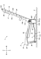
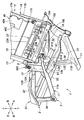
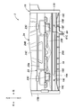
- Perspective view of the frame of the vehicle seat is a perspective view of the frame of the vehicle seat seen from the rear lower side, and shows the state where the plate member is removed.
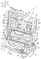
- Perspective view of the reclining drive unit Front view showing the bottom of the seat back frame
- Sectional drawing which shows the connection part of the lower member and a reclining drive device.
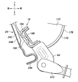
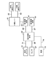
- Side view showing the lower end of the lower part of the side member Explanatory drawing showing connection structure of control cable and harness
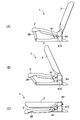
- a side view showing (A) usage mode, (B) transition state from usage mode to storage mode, and (C) storage mode of the vehicle seat.
- Sectional drawing which shows the connection part of the lower member and the reclining drive device which concerns on a modification embodiment.
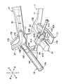
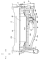
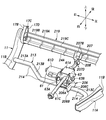
- FIG. 1 Front view of the bottom of the vehicle seat Perspective view of vehicle seat A perspective view showing the structure of the base cross member and its surroundings according to the second embodiment.
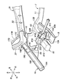
- Top view of the inside of the seat cushion according to the third embodiment It is a perspective view which looked at the seat cushion frame which concerns on 3rd Embodiment from the rear lower part, and is the figure which shows the connection part of the seat-like member and the lower member.
- Sectional drawing of the seat cushion which concerns on 3rd Embodiment Perspective view of the sheet according to the third embodiment The figure which shows the cover of the seat cushion frame which concerns on 4th Embodiment
- Top view of the inside of the seat cushion according to the fifth embodiment Sectional drawing of the seat cushion which concerns on 5th Embodiment Sectional view of the locking device and its surrounding structures Sectional view of the locking device and its surrounding structures
- the vehicle seats 1 and 200 vary in form between a usage form (seating form) and a storage form. Unless otherwise specified, the shapes and orientations of the configurations of the vehicle seats 1 and 200 will be described with reference to the usage pattern. Further, when it is described that each member is connected, the joining mode shall include welding and fastening unless otherwise specified.
- the vehicle seat 1 has a seat cushion 2 and a seat back 3.
- the seat back 3 is rotatably supported by the floor 4, and the seat cushion 2 is rotatably supported by the seat back 3.
- a lock device 5 that selectively regulates the rotation of the seat back 3 with respect to the floor 4 is provided between the seat back 3 and the floor 4.
- the seat back 3 stands up against the floor 4 and the seat cushion 2 is separated upward from the floor 4.
- the vehicle seat 1 becomes a storage form by rotating the seat back 3 forward.
- the seat cushion 2 moves downward and comes close to the floor 4.
- the seat back 3 extends substantially horizontally and overlaps the seat cushion 2.
- the floor 4 is provided with a base 7.
- the base 7 extends left and right on the upper surface of the floor 4 to the left and right base side members 11 connected to the floor 4, and left and right base pillars 12 extending upward from the rear ends of the left and right base side members 11.
- It has a base cross member 13 that extends and is coupled to the left and right base side members 11.
- Each of the base side member 11, the base pillar 12, and the base cross member 13 is formed of sheet metal.
- the left and right base side members 11 have a bottom wall portion 11A whose surface faces up and down and is connected to the floor 4, and a vertical wall portion extending upward from the side edge of the bottom wall portion 11A.
- the base pillar 12 and the base side member 11 may be formed of a common sheet metal or may be formed of a sheet metal independent of each other.
- the base pillar 12 on the right side is integrally formed with the base side member 11.
- the base pillar 12 on the left side is formed by a sheet metal independent of the base side member 11 and is connected to the base side member 11.
- the base pillar 12 has a plate-shaped pillar main body portion 12A whose surface faces left and right, and a pillar edge wall portion 12B extending outward from the leading edge and the trailing edge of the pillar main body portion 12A.
- the base cross member 13 has a lower channel material 13A having a groove-shaped cross section that opens upward and an upper channel material 13B having a groove-shaped cross section that opens downward.
- the length of the upper channel material 13B in the left-right direction is shorter than the length of the lower channel material 13A in the left-right direction.
- the upper channel material 13B and the lower channel material 13A cooperate to form a closed cross-sectional structure.
- the upper channel material 13B may be fitted inside the lower channel material 13A.
- the left and right ends of the lower channel member 13A are coupled to the vertical wall portion 11B of the corresponding base side member 11.
- the left end portion of the upper channel material 13B is connected to the left vertical wall portion 11B.
- the right end portion of the upper channel material 13B is arranged to the left of the center in the left-right direction of the lower channel material 13A. It is preferable that the bottoms of the lower channel material 13A and the upper channel material 13B are provided with an uneven structure such as a beat in order to increase the rigidity.
- the seat back 3 has a seat back frame 16.
- a pad (not shown) is supported on the seat back frame 16, and the pad and the seat back frame 16 are covered with a skin material (not shown).
- the seat back frame 16 has left and right backside members 17, an upper member 18, a lower member 19, a first cross member 21, a second cross member 22, a third cross member 23, and a plate member 24.
- the left and right backside members 17 extend vertically with a space between the left and right backside members 17.
- the upper member 18 extends to the left and right and is connected to the upper ends of the left and right backside members 17.
- the lower member 19 extends below the upper member 18 to the left and right, and is connected to the lower part of the left and right backside members 17.
- the first to third cross members 21 to 23 extend left and right between the upper member 18 and the lower member 19, and are connected to the middle portion of the left and right backside members 17.
- the left and right backside members 17 have a side member upper portion 17A and a side member lower portion 17B connected to the side member upper portion 17A.
- the left and right side member upper portions 17A and the upper member 18 are formed by bending a continuous pipe material.
- the left and right side member lower portions 17B have a main body portion 17C formed of sheet metal and whose surface faces left and right, and an edge wall portion 17D bent inward from the edge of the main body portion 17C.
- the upper member 18 is provided with left and right headrest support portions 26.
- the left and right headrest support portions 26 are coupled to the front surface of the central portion of the upper member 18 in the left-right direction at a distance from each other.
- the left and right headrest support portions 26 are formed in a cylindrical shape and extend downward from the upper member 18.
- the lower member 19 has a rear channel material 19A having a cross-section groove opening toward the front and a front channel material 19B having a cross-section groove opening toward the front.
- the length of the front channel material 19B in the left-right direction is shorter than the length of the rear channel material 19A in the left-right direction.
- the rear channel material 19A and the front channel material 19B cooperate to form a closed cross-sectional structure.
- the front channel material 19B may be fitted inside the rear channel material 19A.
- the left and right ends of the rear channel material 19A are arranged inside the edge wall portion 17D of the corresponding side member lower portions 17B on the left and right, and are welded to the edge wall portion 17D.
- the end portion of the edge wall portion 17D of the side member lower portion 17B is welded to the rear surface of the rear channel material 19A.
- the end of the rear channel material 19A has an extension 19C to increase the contact area of the side member lower portion 17B with the edge wall portion 17D.
- the extension portion 19C may be provided at the tip of the side wall portion forming the groove shape of the rear channel material 19A.
- the left end of the front channel material 19B is connected to the main body 17C of the left side member lower portion 17B.
- the right end portion of the front channel material 19B is arranged to the left of the center in the left-right direction of the rear channel material 19A.
- the bottoms of the rear channel material 19A and the front channel material 19B are provided with convex portions 19D such as beads in order to increase the rigidity.
- the convex portion 19D bulges toward the front channel material 19B and is in contact with the front channel material 19B. Further, the convex portion 19D may extend to the left and right along the rear channel material 19A.
- the first cross member 21 and the second cross member 22 are formed of a rod-shaped member having a circular cross section.
- the first cross member 21 extends to the left and right below the upper member 18 and above the lower member 19.
- the left and right end portions 21A of the first cross member 21 are bent upward with respect to the central portion and welded to the corresponding side member upper portion 17A.
- the second cross member 22 extends to the left and right below the first cross member 21 and above the lower member 19.
- the left and right ends of the second cross member 22 are bent upward with respect to the central portion and welded to the corresponding side member upper portion 17A.
- the third cross member 23 extends to the left and right below the second cross member 22 and above the lower member 19, and is welded to the left and right side member lower portions 17B.
- the third cross member 23 may be formed of a plurality of sheet metal members.
- the third cross member 23 has a main body portion 23A whose surface faces forward and backward, and a bent portion 23B that extends forward and upward from the lower edge of the main body portion 23A and then further bends and extends downward.
- An anchor 23C projecting forward is provided on the lower edge of the third cross member 23. The anchor 23C is used to lock the hook of the child seat.
- the plate member 24 has its surface facing forward and backward, and is welded to the left and right backside members 17, the upper member 18, the lower member 19, and the third cross member 23.
- the upper edge of the plate member 24 is located above the upper member 18 and extends to the left and right.
- the lower edge of the plate member 24 is located below the lower member 19 and extends to the left and right.
- the left and right side edges of the plate member 24 are located on the left and right outer sides of the left and right back side members 17, and extend vertically.
- a curved portion 24A curved in an arc shape is provided at each edge portion of the plate member 24.
- the curved portion 24A has a semi-circular cross section that is convex toward the front and extends along each edge portion.
- each curved portion 24A is provided with a concavo-convex structure such as a plurality of beads.
- Each uneven structure may extend in a direction orthogonal to the extending direction of the curved portion 24A.
- Each curved portion 24A and each uneven structure improve the rigidity of the plate-shaped portion.
- the plate member 24 has a flat surface portion 24B whose surface faces forward and backward, and a plurality of raised portions 24C raised from the flat surface portion 24B.
- the raised portion 24C may be raised forward or backward with respect to the flat surface portion 24B.
- Each raised portion 24C is formed by pushing a plate-shaped portion forward or backward. The raised portion 24C improves the rigidity of the plate member 24.
- At least one through hole 19E penetrating back and forth is formed in the rear channel material 19A and the front channel material 19B of the lower member 19.
- the through hole 19E of the front channel material 19B is arranged at a position overlapping the through hole 19E of the rear channel material 19A in the front-rear direction.
- the plate member 24 is provided with a sign for aligning with the lower member 19.
- the sign may be a hole, a convex portion, a concave portion, a design, or the like.
- the left and right backside members 17, upper members 18, and lower members 19 may be integrally formed with the plate member 24.
- a three-dimensional shape may be formed by press-molding the plate member 24, and this three-dimensional shape may form a backside member 17, an upper member 18, and a lower member 19.
- the outer shape of the electronic control device 42 should be formed so as not to give a sense of discomfort to the back of the seated person.
- the outer shape of the left portion of the electronic control device 42 provided on the right side of the seat back 3 may be formed by a surface inclined rearward toward the left. Further, the outer shape of the left portion of the electronic control device 42 may be formed by a smooth curved surface. With this configuration, the electronic control device 42 provided on the seat back 3 can reduce the discomfort given to the back of the seated person.
- the left and right side member lower portions 17B are rotatably supported by the corresponding base pillars 12 on the left and right via the lock device 5.
- the rotation axes of the left and right side member lower portions 17B extend to the left and right and are arranged coaxially with each other.
- the lock device 5 is arranged coaxially with the rotation axis of the side member lower portion 17B.
- the locking device 5 has an operating shaft 5A that extends along the rotation axis of the backside member 17, penetrates the backside member 17, and projects inward to the left and right of the backside member 17.
- the rotation of the operation shaft 5A allows or restricts the rotation of the backside member 17 with respect to the floor 4.
- a known reclining mechanism can be applied to the locking device 5.
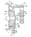
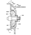
- the locking device 5 includes, for example, a first portion 603A coupled to the base pillar 12 and a second portion 603B coupled to the lower side member 17B and rotatably supported by the first portion 603A (see FIG. 27).
- a lock claw provided on the second portion 603B and movable between the coupling position connected to the first portion 603A and the release position away from the first portion 603A, a spring for urging the lock claw to the coupling position, and a spring.
- the lock claw is attached to the spring by rotating. It is preferable to have a cam that moves to the release position against the force.
- the seat cushion 2 has a seat cushion frame 31.
- a pad is supported on the seat cushion frame 31, and the pad and the seat cushion frame 31 are covered with a skin material.
- the seat cushion frame 31 has left and right cushion side members 32, a front member 33, a rear member 34, and a center plate 35.
- the left and right cushion side members 32 extend back and forth with a space between the left and right cushion side members 32.
- the front member 33 extends to the left and right and is connected to the front ends of the left and right cushion side members 32.
- the rear member 34 extends to the left and right and is connected to the rear ends of the left and right backside members 17.
- the center plate 35 extends back and forth and is joined to the front member 33 and the rear member 34.
- the left and right rear links 37 extending rearward and upward are connected to the rear ends of the left and right cushion side members 32.
- the left and right rear links 37 move integrally with the left and right cushion side members 32.
- the rear ends of the left and right rear links 37 are rotatably supported by the left and right side member lower portions 17B about an axis extending to the left and right. As a result, the seat cushion 2 is rotatably coupled to the seat back 3.
- the front ends of the left and right cushion side members 32 are connected to the front ends of the base side member 11 via the left and right front links 38.
- One end of the front link 38 is rotatably connected to the front end of the cushion side member 32 about an axis extending to the left and right.
- the other end of the front link 38 is rotatably connected to the front end of the base side member 11 about an axis extending to the left and right.
- the seat back frame 16 is provided with a lock device drive device 41 for driving the lock device 5 and an electronic control device 42 for controlling the lock device drive device 41.
- the electronic control device 42 includes a CPU, a non-volatile memory (ROM), a volatile memory (RAM), and the like.
- the lock device drive device 41 and the electronic control device 42 are arranged side by side on one side of the seat back frame 16 in the left-right direction. In the present embodiment, the lock device drive device 41 and the electronic control device 42 are arranged side by side on the right side of the seat back frame 16.
- the electronic control device 42 is coupled to the plate member 24 via the first bracket 44.
- the first bracket 44 may be welded to the plate member 24, or may be fastened to the plate member 24 by fastening members such as bolts and nuts.
- the first bracket 44 is coupled to at least one of the flat surface portion 24B and the raised portion 24C so as to overlap the flat surface portion 24B and the raised portion 24C when viewed from a direction orthogonal to the plate member 24.
- the first bracket 44 has a first portion 44A coupled to the flat surface portion 24B and a second portion 44B that is offset forward with respect to the first portion 44A and abuts on the raised portion 24C.
- the second portion 44B may be coupled to the raised portion 24C.
- the electronic control device 42 is fastened to the second portion 44B by fastening members such as bolts and nuts.
- the first portion 44A may be coupled to the backside member 17 in addition to the flat surface portion 24B.
- the electronic control device 42 and the first bracket 44 are arranged at one of the left and right backside members 17 and a corner defined by the upper member 18.
- the electronic control device 42 and the first bracket 44 are arranged at the corners defined by the backside member 17 and the upper member 18 on the right side. Further, at least a part of the electronic control device 42 is arranged between the corresponding backside member 17 and the headrest support portion 26 on the left and right sides.
- the upper portion of the electronic control device 42 is arranged between the upper portion of the backside member 17 on the right side and the headrest support portion 26 on the right side. Further, the electronic control device 42 and the first bracket 44 are arranged above the first cross member 21.
- the electronic control device 42 is arranged in a space defined by a backside member 17, a headrest support portion 26, an upper member 18, and a first cross member 21 corresponding to each other on the left and right sides.
- the outer shape of the electronic control device 42 should be formed so as not to give a sense of discomfort to the back of the seated person.
- the outer shape of the left portion of the electronic control device 42 provided on the right side of the seat back 3 may be formed by a surface inclined rearward toward the left. Further, the outer shape of the left portion of the electronic control device 42 may be formed by a smooth curved surface. With this configuration, the electronic control device 42 provided on the seat back 3 can reduce the discomfort given to the back of the seated person.
- the lock device drive device 41 has a lock device electric motor 41A and an output unit 41B that is displaced according to the drive of the lock device electric motor 41A.
- the lock device drive device 41 is coupled to the backside member 17 via the second bracket 46.
- the second bracket 46 is at least one first projecting piece that protrudes to the right from the main body portion 46A to which the lock device drive device 41 is fastened and the main body portion 46A and is coupled to the side member upper portion 17A. It has a portion 46B and at least one second projecting piece portion 46C protruding to the left from the main body portion 46A and coupled to a flat portion 24B or a raised portion 24C of the plate member 24.
- the main body portion 46A, the first projecting piece portion 46B, and the second projecting piece portion 46C may be formed of different members from each other and may be coupled to each other. Further, the main body portion 46A, the first protruding piece portion 46B, and the second protruding piece portion 46C may be formed from one plate member 24.
- the first projecting piece portion 46B is curved in a semi-circular shape and extends along the outer circumference of the side member upper portion 17A.
- two first projecting piece portions 46B are arranged vertically at intervals.
- the upper first projecting piece portion 46B is arranged below the end portion 21A of the first cross member 21.
- the end portion 21A of the first cross member 21 is bent to the side opposite to the second bracket 46.
- the two first projecting piece portions 46B may be welded to or fastened to the side member upper portion 17A.
- the second projecting piece portion 46C may be welded to or fastened to the plate member 24.
- the second projecting piece portion 46C and the drive device 41 for the lock device are arranged below the electronic control device 42. Further, the second projecting piece portion 46C and the lock device drive device 41 are arranged below the first cross member 21. That is, the first cross member 21 passes between the lock device drive device 41 and the electronic control device 42 and extends to the left and right.
- a relay lever 51 is rotatably provided on the left side of the plate member 24 and on the right side of the backside member 17 on the left side.
- the relay lever 51 is urged to the initial position by a spring (not shown).
- the lock device drive device 41 is connected to the relay lever 51 via a first control cable 52 (transmission member).
- the relay lever 51 is connected to the operation lever 5B of the lock device 5 on the left side via the second control cable 53 (transmission member), and is connected to the operation lever 5 of the lock device 5 on the right side via the third control cable 54 (transmission member). It is connected to 5B.
- a sensor 57 for detecting the position of the operating lever 5B is provided at the lower end of the backside member 17.
- the sensor 57 is a right side surface of the lower side member 17B on the right side, and is arranged around the operation lever 5B.
- the sensor 57 may be a limit switch that is pushed and rotated by the convex portion 5C of the operating lever 5B.
- the sensor 57 is placed between the corresponding backside member 17 and the rear link 37. That is, the sensor 57 is arranged between the backside member 17 on the right side and the rear link 37 on the right side.
- the operating lever 5B is connected to the lower side member 17B via the spring 5D and is urged toward the initial position.
- the base 7 is provided with a reclining drive device 61 that rotates the seat back frame 16 with respect to the base 7.
- the reclining drive device 61 connects the base 7 and the seat back 3, and rotates the seat back 3 with respect to the base 7 by expanding and contracting.
- the reclining drive device 61 is coupled to the case 61A, the ball screw nut 61B rotatably supported by the case 61A, the ball screw shaft 61C screwed to the ball screw nut 61B, and the ball screw nut 61A. It has a reclining electric motor 61D that rotates the 61B.
- the case 61A is rotatably connected to the base cross member 13 via a hinge 63 about an axis extending to the left and right.
- the hinge 63 is rotatably coupled to the lower hinge bracket 63A, which is fastened to the upper channel material 13B of the base cross member 13, and to the lower hinge bracket 63A about an axis extending to the left and right, and is fastened to the case 61A.
- It also has an upper hinge bracket 63B.
- a work hole 13C which is a through hole, is formed at the bottom of the lower channel material 13A of the base cross member 13.
- the bolt 13D that fastens the upper channel material 13B and the lower hinge bracket 63A is exposed downward through the work hole 13C. As a result, the operator can perform the fastening work between the upper channel material 13B and the lower hinge bracket 63A through the work hole 13C.
- a bracket 64 extending downward is welded to the lower member 19 of the seat back frame 16.
- the bracket 64 may be welded to the outer surface of the lower side wall of the lower channel member 19A of the lower member 19.
- the tip of the ball screw shaft 61C is rotatably connected to the bracket 64 about an axis extending to the left and right.
- it is preferable that the tip of the ball screw shaft 61C is provided with a bent portion 61E bent upward.
- the bent portion 61E is rotatably coupled to the connecting portion 19F integrally formed with the rear channel material 19A about an axis extending to the left and right.
- the connecting portion 19F may be formed, for example, by cutting up the rear channel material 19A.
- the reclining drive device 61 is arranged behind the front end of the seat cushion 2.
- the reclining drive device 61 is provided on the base cross member 13 behind the front member 33 of the seat cushion frame 31.
- the reclining drive device 61 is arranged on the left side of the base cross member 13.
- the axis of the ball screw shaft 61C extends in the front-rear direction.
- the axis of the ball screw shaft 61C is orthogonal to the rotation axis of the reclining electric motor 61D in a plan view.
- the reclining electric motor 61D is arranged behind the base cross member 13.
- the rotation axis of the reclining electric motor 61D extends in the left-right direction and extends substantially parallel to the base cross member 13.
- the front end of the reclining electric motor 61D is arranged at a distance from the base cross member 13.
- the upper wall portion of the reclining electric motor 61D may be above the upper portion of the right portion of the base cross member 13.
- the upper wall portion of the reclining electric motor 61D may be on the same horizontal plane as the upper portion of the right portion of the base cross member 13.
- the upper wall portion of the reclining electric motor 61D may be below the upper portion of the right portion of the base cross member 13.
- the electronic control device 42 is connected to the lock device drive device 41 by the first harness 66, is connected to the reclining drive device 61 by the second harness 67, and is connected to the reclining drive device 61 by the third harness 68. It is connected to the sensor 57.
- the first to third harnesses 66 to 68 are partially bound to each other.
- a part of the second harness 67 is fastened to the lower member 19 by a plurality of resin fasteners 69 and is arranged along the lower member 19.
- a part of the second harness 67 may be fastened to the third cross member 23 by a plurality of resin fasteners 69 and may be arranged along the third cross member 23.
- the electronic control device 42 is connected to the operation switch 72 by the fourth harness 71, and is connected to the power supply 75 by the fifth harness 74.
- the operation switch 72 outputs the first signal according to the first operation of the occupant and outputs the second signal according to the second operation.
- the first signal is a signal corresponding to the operation of changing the vehicle seat 1 from the usage form to the storage form
- the second signal is a signal corresponding to the operation of changing the vehicle seat 1 from the storage form to the usage form.
- the operation of the vehicle seat 1 will be described.
- the seat back 3 stands up against the floor 4, and the lock device 5 restricts the rotation of the seat back 3.
- the seat cushion 2 extends substantially horizontally and is arranged at a distance from the floor 4.
- the first signal is output to the electronic control device 42.
- the electronic control device 42 drives and controls the lock device drive device 41 based on the first signal.
- the lock device drive device 41 moves the relay lever 51 from the initial position to the drive position by the first control cable 52.
- the electronic control device 42 determines that the operation lever 5B has reached the release position, that is, the lock device 5 has been released, based on the signal from the sensor 57.
- the electronic control device 42 drives and controls the reclining electric motor 61D of the reclining drive device 61 to extend the reclining drive device 61.
- the reclining electric motor 61D rotates, the ball screw nut 61B rotates with respect to the case 61A, and the ball screw shaft 61C projects rearward with respect to the case 61A.
- the vehicle seat 1 becomes a storage form.
- the electronic control device 42 detects that the ball screw shaft 61C has reached the longest position based on the drive current of the reclining electric motor 61D of the reclining drive device 61, and stops the drive of the reclining drive device 61.
- the electronic control device 42 measures the elapsed time from the time when the lock device 5 is determined to be released, and stops the drive of the lock device drive device 41 when the elapsed time reaches a predetermined time.
- the locking device 5 is changed from the released state to the locked state by the urging force of the springs of the left and right locking devices 5.
- FIG. 10 (C) the vehicle seat 1 is maintained in the stored form.
- the second signal is output to the electronic control device 42.
- the electronic control device 42 drives and controls the lock device drive device 41 based on the second signal.
- the lock device drive device 41 moves the left and right operation levers 5B from the lock position to the release position via the first control cable 52, the relay lever 51, the second control cable 53, and the third control cable 54.
- the left and right lock devices 5 are released, and the seat back 3 can rotate with respect to the base 7.
- the electronic control device 42 determines that the operation lever 5B has reached the release position based on the signal from the sensor 57, that is, the lock device 5 has been released.
- the electronic control device 42 drives and controls the reclining electric motor 61D of the reclining drive device 61 to contract the reclining drive device 61.
- the reclining electric motor 61D rotates
- the ball screw nut 61B rotates with respect to the case 61A
- the ball screw shaft 61C moves forward with respect to the case 61A.
- FIG. 10B the lower end portion of the seat back 3 is pulled forward by the reclining drive device 61, and the upper portion of the seat back 3 rotates backward.
- the electronic control device 42 detects that the ball screw shaft 61C has reached the shortest position based on the drive current of the reclining electric motor 61D of the reclining drive device 61, and stops the drive of the reclining drive device 61. Further, the electronic control device 42 measures the elapsed time from the time when the lock device 5 is determined to be released, and stops the drive of the lock device drive device 41 when the elapsed time reaches a predetermined time. As a result, the locking device 5 is changed from the released state to the locked state by the urging force of the springs of the left and right locking devices 5. As a result, as shown in FIG. 10 (A), the vehicle seat 1 is maintained in the usage mode.
- the electronic control device 42 can be arranged at a position that does not interfere with the operation of the vehicle seat 1.
- the thickness of the seat cushion 2 can be reduced. Further, it is possible to secure a space for the seat cushion 2 to move below the seat cushion 2.
- the influence of the electronic control device 42 and the lock device drive device 41 on the back of the occupant can be suppressed.
- the first bracket 44 that supports the electronic control device 42 is arranged so as to overlap the flat surface portion 24B and the raised portion 24C in the plate member 24. As a result, the first bracket 44 is arranged in a portion of the plate member 24 having high rigidity, and the first bracket 44 and the electronic control device 42 are stably supported by the seat back frame 16.
- the electronic control device 42 is arranged at a corner defined by the upper member 18 and the backside member 17. Further, the electronic control device 42 is arranged in the space defined by the upper member 18, the backside member 17, the first cross member 21, and the headrest pillar. Therefore, the electronic control device 42 can be arranged by effectively utilizing the space formed by the upper member 18, the backside member 17, and the plate member 24. In addition, the influence of the electronic control device 42 on the back of the occupant can be suppressed.
- the lock device drive device 41 is arranged below the electronic control device 42, the electronic control device 42 and the lock device drive device 41 can be arranged in the seat back 3 with high space efficiency. Further, since the first cross member 21 is arranged between the electronic control device 42 and the lock device drive device 41, the seat back frame 16 of the portion to which the electronic control device 42 and the lock device drive device 41 are attached. Rigidity can be improved. Since the end portion 21A of the first cross member 21 coupled to the backside member 17 is bent upward, it is possible to avoid interference with the second bracket 46 coupled to the backside member 17.
- the vehicle seat 200 according to the second embodiment has a different structure around the reclining drive device 61 as compared with the vehicle seat 1 according to the first embodiment.
- the different configurations will be described, and the description of the same configuration as that of the vehicle seat 1 according to the first embodiment will be omitted by referring to the above description.
- the base cross member 213 is formed of a pipe material having at least one bent portion 214.
- the left and right ends of the base cross member 213 are coupled to the vertical wall portion 11B of the corresponding base side member 11.
- the base cross member 213 is partitioned by a plurality of bends 214 and has a right portion 213A, a central portion 213B, and a left portion 213C.
- the right portion 213A, the central portion 213B, and the left portion 213C each extend linearly.
- the right portion 213A is arranged above the left portion 213C.
- the central portion 213B is inclined upward toward the right.
- the left portion 213C is formed longer in the left-right direction with respect to the right portion 213A.
- Bracket 206 is connected to the left portion 213C of the base cross member 213.
- the bracket 206 has a main body portion 206A whose surface faces up and down, and left and right side wall portions 206B extending downward from the left and right side edges of the main body portion 206A.
- a semi-circular recess 206C is formed at the lower end of the side wall portion 206B.
- the upper portion of the base cross member 213 is received and welded to the recess 206C.
- a lower hinge bracket 63A is fastened to the main body 206A of the bracket 206. With this configuration, the configuration of the base cross member 213 can be simplified and the rigidity can be improved. Further, the reclining drive device 61 can be fixed to the curved base cross member 213 via the bracket 206.
- the lower member 219 of the seat back frame 16 is formed of a channel material having a groove-shaped cross section that opens toward the front.
- the lower member 219 has a side wall portion 219A whose surface faces forward and backward, an upper wall portion 219B extending forward from the upper edge of the side wall portion 219A, and a lower wall portion 219C extending forward from the lower edge of the side wall portion 219A.
- the vertical width of the side wall portion 219A is wider than the front-rear width of the upper wall portion 219B, and the vertical width of the side wall portion 219A is wider than the front-rear width of the lower wall portion 219C.
- the left and right ends of the side wall portion 219A of the lower member 219 are welded to the inside of the edge wall portion 17D of the corresponding side member lower portion 17B on the left and right.
- the lower member 219 is coupled to the backside member 17 at the side wall portion 219A which is wider than the upper wall portion 219B and the lower wall portion 219C, so that the rigidity of the coupling portion can be improved.
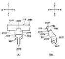
- a bracket 207 is connected to the lower member 219.
- the bracket 207 has a rear wall portion 207A whose surface faces forward and backward, and left and right edge wall portions 207B extending forward from the left and right side edges of the rear wall portion 207A.
- the rear wall portion 207A and the left and right edge wall portions 207B are formed by bending a sheet metal.
- the upper end portion 207C of the rear wall portion 207A extends upward from the upper end portion 207C of the left and right edge wall portions 207B, and is in surface contact with the rear surface of the side wall portion 219A of the lower member 219.
- the upper end portion 207C of the rear wall portion 207A is welded to the rear surface of the side wall portion 219A of the lower member 219.
- the upper end portion 207C of the left and right edge wall portions 207B is in contact with the lower surface of the lower wall portion 219C of the lower member 219 and is welded.
- the edge wall portion 207B of the bracket 207 extends downward and forward.
- the left and right edge wall portions 207B face left and right, and correspond to each other through a gap in the left and right directions.
- the left and right edge wall portions 207B are bent at an intermediate portion in the vertical direction so that the distance between the lower end portions 207D is smaller than the distance between the upper end portions 207C.
- Support holes 207E penetrating left and right are formed in the lower end portions 207D of the left and right edge wall portions 207B.
- a shaft 208 is inserted into the support hole 207E.
- the rear end portion of the ball screw shaft 61C is arranged between the left and right edge wall portions 207B and is rotatably supported by the shaft 208. Since the bracket 207 extends downward and forward, the bracket 207 can compactly accommodate the ball screw shaft 61C under the seat back 3 when the vehicle seat 200 is in the stowed state.
- a luggage compartment 201 is provided behind the vehicle seat 200.
- the floor 4 defining the lower part of the luggage compartment 201 is provided with a recess 220 recessed downward.
- the recess 220 can store an article 221 such as a tire.
- a luggage compartment board 202 is provided on the upper surface of the floor 4 so as to cover the recess 220.
- the luggage compartment board 202 is detachably provided with respect to the floor 4 and extends horizontally.
- the luggage compartment board 202 is made of, for example, resin.
- a cover 203 is provided on the leading edge of the luggage compartment board 202.
- the cover 203 extends in the left-right direction of the vehicle seat 200.
- the front end of the cover 203 is arranged on the back surface of the seat back 3. That is, the cover 203 is provided so as to cover the gap between the luggage compartment board 202 and the seat back 3.
- the cover 203 may be integrally molded with the luggage compartment board 202.
- the cover 203 is arranged above the rear end of the ball screw shaft 61C.
- the bracket 207 extends forward and downward.
- the cover 203 can hide the gap between the vehicle seat 200 and the luggage compartment board 202 and the rear end of the ball screw shaft 61C.
- a sensor 204 is provided on the upper part of the seat cushion 2. Specifically, the sensor 204 is arranged between the upper surface of the pad constituting the seat cushion 2 and the skin material.
- the sensor 204 is a load sensor that detects a load.
- the sensor 204 may be, for example, a piezoelectric element, a membrane switch that deforms according to a load and is connected to contacts, or the like.
- the sensor 204 is provided to detect whether or not an object is present on the seat cushion 2.
- the sensor 204 is a membrane switch and outputs an ON signal when a load of a predetermined value or more is applied.
- the sensor 204 is connected to the electronic control device 42.
- the sensor 204 outputs a signal to the electronic control device 42 according to the detected pressure.
- the electronic control device 42 regulates the deformation from the usage mode to the storage mode when it is determined that an object exists on the seat cushion 2 based on the signal from the sensor 204. Specifically, the electronic control device 42 prohibits the drive of the lock device drive device 41 when the ON signal is received from the sensor 204. With this configuration, it is possible to prevent the vehicle seat 200 from changing to the storage form when an object is placed on the seat cushion 2 or when a seated person is present.
- the sensor 204 may be, for example, a strain sensor 222 provided between the upper hinge bracket 63B and the case 61A, as shown in FIG.
- the strain sensor 222 is a known strain sensor, and outputs a signal corresponding to the strain to the electronic control device 42.
- the strain sensor 222 is compressed between the upper hinge bracket 63B and the case 61A.
- the electronic control device 42 can detect the pinching of the object by the seat cushion 2 and the seat back 3 based on the signal from the strain sensor 222.
- the strain sensor 222 the sensor 204 can be omitted and the structure of the seat cushion 2 can be simplified.
- the electronic control device 42 may detect pinching of an object by the seat cushion 2 and the seat back 3 based on the current flowing through the reclining electric motor 61D.
- the vehicle seat 200 is provided with an indicator 205.
- the indicator 205 is a display device including, for example, an LED.
- the indicator 205 may be located at the upper left end of the seat back 3.
- the indicator 205 is connected to the electronic control device 42.
- the electronic control device 42 lights the indicator 205 when the ball screw shaft 61C is in the longest position and the operation lever 5B is in the initial position. With this configuration, the user can visually confirm that the vehicle seat 200 has completely changed to the storage form.
- the electronic control device 42 may turn on the indicator 205 when the operating lever 5B is not in the initial position. In this case, the user can visually confirm that the lock device 5 is in the released state.
- the methods for manufacturing the vehicle seats 1 and 200 include a step of rotatably providing the seat back 3 on the base 7, a step of rotatably providing the seat cushion 2 on the seat back 3, and a seat back 3 with respect to the base 7. It is preferable to have a step of connecting the reclining drive device 61 for rotating the seat cushion 2 to the base 7 and the seat back 3 and providing the seat cushion 2 behind the front end.
- the vehicle seats 1 and 200 provided with the reclining drive device 61 can be unitized. This facilitates attachment of the vehicle seats 1 and 200 to the vehicle.
- the vehicle seat 300 according to the third embodiment has a different internal structure of the seat cushion 2 as compared with the vehicle seats 1 and 200 according to the first embodiment and the second embodiment.
- the vehicle seat 300 according to the third embodiment has a different internal structure of the seat cushion 2 as compared with the vehicle seats 1 and 200 according to the first embodiment and the second embodiment.
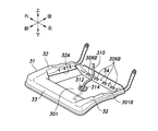
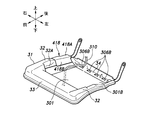
- the vehicle seat 300 has a sheet-like member 301 instead of the center plate 35.
- the sheet-shaped member 301 extends back and forth and is hung between the front member 33 and the rear member 34.
- the sheet-shaped member 301 has a surface facing up and down, and its leading edge 301A and trailing edge 301B extend to the left and right.
- the sheet-like member 301 is flexible and may be formed of, for example, a woven fabric.
- the sheet-shaped member 301 may be formed of, for example, PET resin or the like.
- a reinforcing thread 302 may be sewn on the sheet-shaped member 301.
- the reinforcing thread 302 improves the tensile strength of the sheet-shaped member 301.
- the reinforcing thread 302 may have, for example, left and right side portions 302A extending back and forth, and a central portion 302B extending from the front end of one side portion 302A to the rear end of the other side portion 302A. It is preferable that the left and right side portions 302A and the central portion 302B are formed in a straight line, and the reinforcing threads 302 are arranged in an N shape.
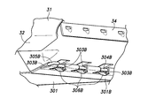
- the sheet-shaped member 301 has a plurality of cylindrical front holding holes 303A extending to the left and right on its leading edge 301A.
- the front holding hole 303A may be formed by folding back the leading edge 301A of the sheet-shaped member 301 and sewing it to the main body of the sheet-shaped member 301.
- a gap is formed between the adjacent front holding holes 303A.
- a front shaft 304A extending to the left and right is inserted into each front holding hole 303A.
- the front shaft 304A has bent portions 305A bent forward at both left and right ends thereof. The bent portion 305A determines the left-right position of the front shaft 304A with respect to each front holding hole 303A.
- the sheet-shaped member 301 has a plurality of cylindrical rear holding holes 303B extending to the left and right on the trailing edge 301B.
- the rear holding hole 303B may be formed by folding back the trailing edge 301B of the sheet-shaped member 301 and sewing it to the main body of the sheet-shaped member 301.
- a gap is formed between the adjacent rear holding holes 303B.
- a rear shaft 304B extending to the left and right is inserted into each rear holding hole 303B.
- the rear shaft 304B has bent portions 305B bent rearward at both left and right ends thereof. The bent portion 305B determines the left-right position of the rear shaft 304B with respect to each rear holding hole 303B.
- the front member 33 has a plurality of front locking portions 306A.
- the plurality of front locking portions 306A are arranged side by side on the left and right.
- Each front locking portion 306A may be a protrusion extending forward and downward from the front member 33.
- Each front locking portion 306A may be formed by cutting up the front member 33 downward.
- the rear member 34 has a plurality of rear locking portions 306B.
- the plurality of rear locking portions 306B are arranged side by side on the left and right.
- Each rear locking portion 306B may be a protrusion extending rearward and downward from the rear member 34.
- Each rear locking portion 306B may be formed by cutting up the rear member 34 downward.
- the front shaft 304A is exposed to the outside between the front holding holes 303A and is locked to a plurality of front locking portions 306A.
- the rear shaft 304B is exposed to the outside between the rear holding holes 303B and is locked to the plurality of front locking portions 306A.
- the front shaft 304A is locked to the plurality of front locking portions 306A
- the rear shaft 304B is locked to the plurality of rear locking portions 306B. It is good.
- a pad 307 is provided on the upper part of the seat cushion frame 31.
- the pad 307 is made of a flexible resin material such as urethane foam.
- the sheet-shaped member 301 supports the central portion of the pad 307 from below.
- a sensor 309 is provided on the upper part of the seat cushion 2. Specifically, the sensor 309 is arranged between the upper surface of the pad 307 constituting the seat cushion 2 and the skin material 308.
- the sensor 309 is a load sensor that detects a load.
- the sensor 309 may be, for example, a piezoelectric element, a membrane switch that deforms according to a load and is connected to contacts, or the like.
- the sensor 309 is provided to detect whether or not the occupant is seated on the seat cushion 2.
- the sensor 309 is a membrane switch and outputs an ON signal when a load of a predetermined value or more is applied.
- the sensor 309 is connected to the electronic control device 42 via the sensor harness 310.
- the pad 307 has a first harness hole 311 that penetrates up and down.
- the sheet-shaped member 301 has a second harness hole 312 that penetrates vertically.
- a grommet 314 is attached to the edge of the second harness hole 312.
- the sensor harness 310 extending from the sensor 309 passes through the first harness hole 311 and the second harness hole 312, and extends downward of the sheet-shaped member 301. It is preferable that the first harness hole 311 and the second harness hole 312 are arranged at overlapping positions when viewed from above. That is, it is preferable that the first harness hole 311 and the second harness hole 312 communicate with each other.
- the harness receiving extending from the first harness hole 311 to the second harness hole 312 on the bottom surface of the pad 307. It is preferable that the groove 307A is formed.
- the harness receiving groove 307A receives the sensor harness 310 extending from the first harness hole 311 to the second harness hole 312.
- the sensor harness 310 extending downward from the second harness hole 312 extends toward the reclining drive device 61 along the base cross member 13 (213).
- the sensor harness 310 is coupled to the base cross member 13 (213) by a resin fastener 69 or the like at one or more portions. Further, a part of the sensor harness 310 is bound together with the second harness 67.
- the sensor harness 310, together with the second harness 67, extends to the lower member 19 (219) and then extends to the electronic control device 42.
- the vehicle seat 300 has a regulating portion 315 protruding forward from the seat back 3 at the position of use.
- the regulation unit 315 regulates the load applied to the sensor 309 by the seat back 3 to be suppressed to a predetermined value or less when the vehicle seat 300 is in the storage position.
- the regulating portion 315 may be composed of the pad 307 and the skin material 308 covering the pad 307, and may be integrally formed with the seat back 3.
- the regulation unit 315 may be, for example, side support units 316 provided on the left and right side portions of the seat back 3.
- the left and right side support portions 316 project forward from the left and right side portions on the front surface of the seat back 3. That is, on the front surface of the seat back 3, the portion provided with the left and right side support portions 316 protrudes forward with respect to the central portion of the seat back 3 in the left-right direction.
- the left and right side support portions 316 extend vertically.
- the left and right side support portions 316 come into contact with the left and right side portions of the seat cushion 2, so that between the central portion of the seat back 3 in the left-right direction and the upper surface of the seat cushion 2.
- a gap is formed. This prevents a load from being applied to the sensor 309. This makes it possible to prevent the sensor 309 from erroneously detecting due to the load from the seat back 3.
- the regulation unit 315 may be, for example, a headrest 317 provided on the upper part of the seat back 3.
- the lower part of the headrest 317 may be arranged on the front surface of the seat back 3. That is, the headrest 317 has a portion arranged in front of the front surface of the seat back 3.
- the headrest 317 abuts on the front portion of the seat cushion 2 to form a gap between the front surface of the seat back 3 and the upper surface of the seat cushion 2. This prevents a load from being applied to the sensor 309. This makes it possible to prevent the sensor 309 from erroneously detecting due to the load from the seat back 3.
- the seat cushion 2 can give the occupant a flexible feel. Since the sheet-shaped member 301 is provided with the second harness hole 312, the sensor harness 310 extending from the sensor 309 can extend below the sheet-shaped member 301 without interfering with the sheet-shaped member 301. Further, by attaching the grommet 314 to the edge portion of the second harness hole 312, it is possible to prevent the edge portion of the second harness hole 312 from being damaged by the contact of the sensor harness 310. Further, by providing the grommet 314, it is possible to prevent the sensor harness 310 from being damaged by the contact with the edge portion of the second harness hole 312.
- the seat cushion 2 of the vehicle seat 300 has a step of bridging the seat-shaped member 301 between the front member 33 and the rear member 34, and a sensor on the seat cushion frame 31 and the seat-shaped member 301. It may be manufactured by a manufacturing method including a step of supporting the pad 307 provided with 309.
- the vehicle seat 400 according to the fourth embodiment has a different arrangement of the sensor harness 310 below the seat cushion 2 than the vehicle seat 300 according to the third embodiment. Further, the vehicle seat 400 does not have the second harness hole 312.
- the sensor harness 310 passes through the first harness hole 311 to reach the upper surface of the sheet-shaped member 301, and then passes between the pad 307 and the sheet-shaped member 301 to reach the sheet-shaped member 301. Reach the side edge of. It is preferable that a harness receiving groove 307A extending from the first harness hole 311 toward at least one of the cushion side members 32 is formed on the bottom surface of the pad 307, and the sensor harness 310 is arranged in the harness receiving groove 307A. After that, the sensor harness 310 passes through the space between the sheet-shaped member 301 and one of the left and right cushion side members 32 and extends downward. After that, the sensor harness 310 extends to the reclining drive device 61 side along the base cross member 13 (213).
- the sensor harness 310 is coupled to the base cross member 13 (213) by a resin fastener 69 or the like at one or more portions. Further, a part of the sensor harness 310 is bound together with the second harness 67. The sensor harness 310, together with the second harness 67, extends to the lower member 19 (219) and then extends to the electronic control device 42.
- the cushion side member 32 is equipped with a resin cover 418 extending in the front-rear direction.
- the cover 418 is provided on at least the inner side surface 32A of the cushion side member 32 in the left-right direction.
- the cover 418 has an upper surface portion 418A facing up and down and a hanging portion 418B extending downward from the upper surface portion 418A along the cushion side member 32.
- the cover 418 has a convex boss (not shown) that projects from the back surface of the hanging portion 418B and abuts on the inner surface 32A at the tip.
- the sensor harness 310 may extend downward from the side edge of the sheet-shaped member 301 through the space between the side edge of the sheet-shaped member 301 facing each other in the left-right direction and the cover 418.
- the second harness hole 312 can be omitted from the sheet-shaped member 301.
- the tensile strength of the sheet-shaped member 301 can be improved.
- the cover 418 on the cushion side member 32 contact between the sensor harness 310 and the cushion side member 32 can be avoided, and wear of the sensor harness 310 can be suppressed.
- the vehicle seat 500 according to the fifth embodiment has a different structure of the seat cushion frame 31 and the seat-shaped member 301 as compared with the third embodiment. Further, the seat cushion 2 has a support member 319. In the following description, only the different configurations will be described, and the description of the same configuration as the vehicle seat 300 according to the third embodiment will be omitted by referring to the above description.
- the vehicle seat 500 has a middle member 520 behind the front member 33.
- the middle member 520 extends to the left and right behind the front member 33 and is connected to the left and right cushion side members 32.
- the middle member 520 may be formed of, for example, a pipe material having a circular cross section.
- the rear member 521 may be formed of a pipe material having a circular cross section.
- the vehicle seat 500 has a support member 522.
- the support member 522 extends back and forth and is hung between the middle member 520 and the rear member 521.
- the support member 522 has a surface facing up and down, and its leading edge and trailing edge extend to the left and right.
- the support member 522 is flexible and is formed of, for example, a resin.
- the support member 522 has a front portion 522A, an intermediate portion 522B, and a rear portion 522C in this order from the front side.
- the support member 522 is supported by the middle member 520 at the front portion 522A and supported by the rear member 521 at the rear portion 522C.
- the intermediate portion 522B extends substantially horizontally, the front portion 522A extends forward and upward from the intermediate portion 522B toward the front member 33, and the rear portion 522C extends rearward and upward toward the rear member 521 from the intermediate portion 522B. ..
- the left-right width of the intermediate portion 522B may be set smaller than the left-right width of each of the front portion 522A and the rear portion 522C.
- the intermediate portion 522B is formed in a triangular shape and has a smaller left-right width toward the front.
- each of the front portion 522A and the rear portion 522C is formed in a substantially rectangular shape.
- the left-right width of the front portion 522A is formed to be smaller than the left-right width of the rear portion 522C. It is preferable that at least one lightening hole 523 is formed in each of the front portion 522A, the intermediate portion 522B, and the rear portion 522C.
- the shapes of the front portion 522A, the intermediate portion 522B, the rear portion 522C, and the lightening hole 523 can be arbitrarily set.
- a right extension piece 532A extending to the right and upward from the right edge of the rear portion 522C is provided.
- a left extension piece 532B extending to the left and upward from the left edge of the rear portion 522C is provided.
- the right extension piece 532A and the left extension piece 532B are arranged so as to overlap each other from above the rear portion of the cushion side member 32.
- the sensor harness 310 may pass through the second harness hole 312 in order to prevent damage due to contact with the right extension piece 532A and the left extension piece 532B.
- a plurality of first hook portions 524 that are hooked on the middle member 520 are provided on the leading edge of the front portion 522A of the support member 522.
- Each of the first hook portions 524 is formed in a semicircular shape that opens downward when viewed from the left-right direction.
- a second hook portion 525 that is hooked on the rear member 521 is provided on the trailing edge of the rear portion 522C of the support member 522.
- the second hook portion 525 extends to the left and right along the trailing edge of the rear portion 522C of the support member 522.
- the second hook portion 525 is formed in a semicircular shape that opens downward when viewed from the left-right direction.
- the support member 522 is hung between the middle member 520 and the rear member 521 by hooking the plurality of first hook portions 524 on the middle member 520 and hooking the second hook portion 525 on the rear member 521.
- a sheet-shaped member 301 is bridged between the middle member 520 and the rear member 521.
- At least one front locking portion 526A is provided on the leading edge 301A of the sheet-shaped member 301.
- the front locking portion 526A is formed by bending a metal rod.
- the leading edge 301A of the sheet-shaped member 301 is folded back and sewn to form a plurality of front loop portions 527A.
- Each front loop portion 527A extends to the left and right.
- the front locking portion 526A has a shaft portion 528 rotatably supported by the front loop portion 527A, and left and right third hook portions 529 extending forward from both ends of the shaft portion 528.
- the third hook portion 529 is formed in a semicircular shape that opens downward when viewed from the left-right direction.
- At least one rear locking portion 526B is provided on the trailing edge 301B of the sheet-shaped member 301.
- the rear locking portion 526B is formed by bending a metal rod.
- the trailing edge 301B of the sheet-like member 301 is folded back and sewn to form a plurality of trailing loop portions 527B.
- Each rear loop portion 527B extends to the left and right.
- the rear locking portion 526B has a shaft portion 531 rotatably supported by the rear loop portion 527B, and left and right fourth hook portions 530 extending forward from both ends of the shaft portion 531.
- the fourth hook portion 530 is formed in a semicircular shape that opens downward when viewed from the left-right direction.
- the front locking portion 526A of the sheet-shaped member 301 is locked to the first hook portion 524 of the support member 522, and is locked to the middle member 520 via the first hook portion 524.
- a front engaging groove 524A for receiving the third hook portion 529 is formed on the upper surface of the first hook portion 524 of the support member 522.
- the front engaging groove 524A extends back and forth along the upper surface of the first hook portion 524.
- the rear locking portion 526B of the sheet-shaped member 301 is locked to the second hook portion 525 of the support member 522, and is locked to the rear member 521 via the second hook portion 525.
- a rear engaging groove 525A for receiving the fourth hook portion 530 is formed on the upper surface of the second hook portion 525 of the support member 522.
- the rear engagement groove 525A extends back and forth along the upper surface of the second hook portion 525.
- the central portion 301C in the front-rear direction of the seat-shaped member 301 is located at a position away from the central portion 522D of the support member 522.
- the seat-shaped member 301 bends downward, and the seat-shaped member 301 is supported by the upper surface of the support member 522.
- the lightening hole 523 of the support member 522 is arranged at a position overlapping with the second harness hole 312 of the sheet-shaped member 301.
- the sensor harness 310 that has passed downward through the second harness hole 312 can be extended below the support member 522 through the lightening hole 523. That is, the lightening hole 523 functions as a harness hole for passing the sensor harness 510.
- the support member 522 By supporting the seat-shaped member 301 by the support member 522, the load that can be supported by the seat cushion 2 can be increased. Since the support member 522 is provided with a lightening hole 523, the sensor harness 310 can be easily arranged.
- the pillar main body portion 12A of the base pillar 12 is provided with the first hook bracket 600.
- the first hook bracket 600 is formed of a sheet metal member and has a base 600A facing left and right.
- the base 600A extends along the outer surface of the pillar body 12A and is coupled to the pillar body 12A.
- the first hook bracket 600 has a protruding portion 600B protruding from one end of the base portion 600A toward the left and right outwards.
- a second hook bracket 601 formed of a sheet metal member is provided on the lower side member 17B of the back side member 17.
- the second hook bracket 601 has a base portion 601A coupled along the outer surface of the side member lower portion 17B and a protrusion 601B extending outward from the base portion 601A.
- the tip of the protrusion 601B is arranged above the protrusion 600B.
- Swirl springs 602 are provided on the left and right outer sides of the pillar main body 12A. One end 602A at the center of the spiral spring 602 is supported by the protrusion 600B, and the other end 602B outside the spiral spring 602 is supported by the protrusion 601B.
- the spiral spring 602 urges the seat back frame 16 in the counterclockwise direction with respect to the base pillar 12 when viewed from the left.
- the operator connects each base pillar 12 and each seat back frame 16 via the lock device 5. Specifically, the operator connects the first portion 603A to the pillar main body portion 12A and the second portion 603B to the side member lower portion 17B. As a result, the base pillar 12 and the seat back frame 16 are rotatably connected via the locking device 5.
- the operator covers the operation shaft 5A exposed to the left and right outward from the pillar main body portion 12A, and the gap 605 formed between the first portion 603A and the operation shaft 5A.
- the cap 604 is formed in a cylindrical shape, and one end of the cap 604 is in close contact with the first portion 603A.
- the cap 604 is made of, for example, a resin.
- the operator paints the lock device 5 and the surrounding structure to prevent rust.
- the type of paint may be any as long as it has a rust preventive effect, and in this embodiment, it is cationic electrodeposition coating.
- Cationic electrodeposition coating is performed by immersing the seat back frame 16 including the locking device 5 and the base pillar 12 in the water-soluble electrodeposition coating material. As a result, the seat back frame 16, the base pillar 12, and the locking device 5 are painted. The operator removes the cap 604 after the painting is completed.
- the operator attaches the first hook bracket 600 to the left and right base pillars 12.
- the operator may attach the base portion 600A of the first hook bracket 600 from the left-right direction so as to be along the outer surface of the pillar main body portion 12A.
- the operator attaches the second hook bracket 601 to the left and right backside members 17.
- the operator may attach the base portion 601A of the second hook bracket 601 from the left-right direction so as to be along the side member lower portion 17B.
- the operator may attach the second hook bracket 601 to the lower side member 17B before the painting work.
- the cap 604 can be attached before painting without being interfered by the first hook bracket 600. By attaching the cap 604 before painting, it is possible to prevent the painting liquid from entering the inside of the lock device 5 from the gap 605 formed between the first portion 603A and the operation shaft 5A during the painting work.
- Locking device 7 Base 13, 213: Base cross member 16: Seat back frame 17: Backside member 18: Upper member 19: Lower member 21: First cross member 41: Locking device drive device 41A: Locking device electric motor 42: Electronic control device 44: First bracket 46: Second bracket 61: Reclining drive device 61D: Reclining electric motor 206: Bracket 207: bracket
Landscapes
- Engineering & Computer Science (AREA)
- Aviation & Aerospace Engineering (AREA)
- Transportation (AREA)
- Mechanical Engineering (AREA)
- Health & Medical Sciences (AREA)
- Dentistry (AREA)
- General Health & Medical Sciences (AREA)
- Seats For Vehicles (AREA)
Abstract
【課題】乗物用シートにおいて、シートクッションの前方の空間を広くする。また、本発 明は、乗物用シートにおいて、組付け作業を容易にする。 【解決手段】乗物用シート(1,200)であって、フロア(4)に設けられたベース(7)と、ベース(7)に回動可能に設けられたシートバック(3)と、シートバック(3)に回動可能に設けられたシートクッション(2)と、ベースとシートバック(3)とに接続され、ベース(7)に対してシートバック(3)を回動させるリクライニング用駆動装置(61)とを有し、リクライニング用駆動装置(61)は、シートクッション(2)の前端よりも後方に配置されている。
Description
本発明は、乗物用シート及び乗物用シートの製造方法に関する。
特許文献1は、収納形態においてシートクッションがフロア側に移動するダイブダウンシートを開示している。シートクッション及びフロアは前側脚及び後側脚によって接続され、シートクッション、フロア、前側脚及び後側脚は4節リンクを形成している。前側脚とフロアは、電動モータの駆動力を受けて往復動するスクリューロッドを備えた駆動手段によって接続されている。駆動手段が駆動することによって、前側脚のフロアに対する角度が変化し、シートクッションが移動する。その結果、シートが使用形態から収納形態に変化する。
特許文献1に係るシートでは、駆動手段がフロア上の前側脚の前方に設けられている。そのため、シートクッションの前方の空間が狭くなるという問題がある。また、駆動手段をシートとは別に、フロアに取り付ける必要があるため、シートの組付け作業が煩雑であるという問題がある。
本発明は、以上の背景に鑑み、乗物用シートにおいて、シートクッションの前方の空間を広くすることを課題とする。また、本発明は、乗物用シートにおいて、組付け作業を容易にすることを課題とする。
本発明の一態様は、乗物用シート(1、200)であって、フロア(4)に設けられたベース(7)と、前記ベース(7)に回動可能に設けられたシートバック(3)と、前記シートバック(3)に回動可能に設けられたシートクッション(2)と、前記ベースと前記シートバック(3)とに接続され、前記ベース(7)に対して前記シートバック(3)を回動させるリクライニング用駆動装置(61)とを有し、前記リクライニング用駆動装置(61)は、前記シートクッション(2)の前端よりも後方に配置されている。
この態様によれば、リクライニング用駆動装置がシートクッションの前端よりも後方に配置されているため、シートクッションの前方の空間を広くすることができる。また、リクライニング用駆動装置がベースとシートバックとに接続されているため、リクライニング用駆動装置をフロアに固定する必要がなく、組付け作業を容易にすることができる。
上記の態様において、前記ベース(7)は、前後に延びる左右のベースサイドメンバ(11)と、左右に延びて左右の前記ベースサイドメンバ(11)に結合したベースクロスメンバ(13、213)とを有し、前記リクライニング用駆動装置は、前記ベースクロスメンバ(13、213)に支持されたケース(61A)と、前記ケースに回転可能に支持されたナット(61B)と、前記ケースに結合され、前記ナット(61B)を回転させる駆動力を発生するリクライニング用電動モータ(61D)と、前記ボールねじナット(61B)に螺合して前後に延び、後端において前記シートバック(3)に回動可能に接続されたねじ軸(61C)とを有するとよい。
この態様によれば、リクライニング用駆動装置が左右のベースサイドメンバの間に設けられたベースクロスメンバに配置されているため、1つのリクライニング用駆動装置で安定性良くシートバックを回動させることができる。
上記の態様において、前記ケース(61A)は、ヒンジを介して前記ベースクロスメンバ(13、213)に結合されているとよい。
この態様によれば、シートバックの角度に応じてボールねじ軸を回動させることができるため、シートバックを効率良く回動させることができる。
上記の態様において、前記ベースクロスメンバ(213)は、少なくとも1つの屈曲部(214)を有するパイプ材によって形成されているとよい。
この態様によれば、ベースクロスメンバの構成を簡素にすることができると共に、剛性を向上させることができる。
上記の態様において、前記シートバック(3)は、左右のバックサイドメンバ(17)と、左右に延びて左右の前記バックサイドメンバ(17)に結合したロアメンバ(19)とを有し、前記ねじ軸(61C)の前記後端は、前記ロアメンバ(19)に回動可能に接続されているとよい。
この態様によれば、左右のバックサイドメンバの間に配置されたロアメンバにボールねじ軸が接続されているため、ボールねじ軸からの荷重を安定性良くシートバックに伝達することができる。
上記の態様において、左右の前記バックサイドメンバ(17)は、面が左右を向く板状の本体部(17A)と、前記本体部(17A)の縁から左右内方に突出した縁壁部(17D)とを有し、前記ロアメンバ(19)は、溝形の断面を有し、左右の端部において前記縁壁部(17D)に溶接された第1チャンネル材(19A)を有するとよい。
この態様によれば、ロアメンバの剛性を向上させることができる。これにより、リクライニング用駆動装置からの駆動力をシートバックに効率良く伝達することができる。
上記の態様において、前記ロアメンバ(19)は、前記第1チャンネル材(19A)の内側に配置され、前記第1チャンネル材(19A)に結合された、溝形の断面を有する第2チャンネル材(19B)を有し、前記ねじ軸(61C)の後端は、左右方向において前記第2チャンネル材(19B)と対応する位置において、前記第1チャンネル材(19A)に接続されているとよい。
この態様によれば、ロアメンバにおいてボールねじ軸が接続される部分の剛性を向上させることができる。これにより、リクライニング用駆動装置からの駆動力をシートバックに効率良く伝達することができる。
上記の態様において、前記ロアメンバ(19)には、前記ねじ軸(61C)を回動可能に支持するブラケット(217)が設けられ、前記シートバック(3)が上下に延びた状態において、前記ブラケット(217)は前記ロアメンバ(19)から下方かつ前方に延び、先端部において前記ねじ軸(61C)の後端を左右に延びる軸線を中心として回動可能に支持しているとよい。
この態様によれば、シートバックが水平に延びた状態、すなわちシートの収納状態において、ブラケットがロアメンバから下方に延びるため、ブラケット及びねじ軸の後端がシートバックの背面より下方に配置される。
上記の態様において、前記リクライニング用電動モータ(61D)は、前記ベースクロスメンバ(213)よりも後方に配置されている。
この態様によれば、リクライニング用電動モータ及びナットとシートバックとの距離を短くすることができ、ボールねじ軸を短くすることができる。これにより、リクライニング用駆動装置を小型化することができる。
上記の態様において、前記リクライニング用電動モータ(61D)の回転軸は左右方向に延び、平面視において前記ねじ軸(61C)の軸線は前後方向に延びているとよい。
この態様によれば、リクライニング用電動モータ及びナットとシートバックとの距離を短くすることができ、ボールねじ軸を短くすることができる。これにより、リクライニング用駆動装置を小型化することができる。
上記の態様において、フロア(4)に対する前記シートバック(3)の回動を選択的に規制するロック装置(5)と、前記ロック装置(5)を駆動する、ロック装置用電動モータ(41A)を備えたロック装置用駆動装置(41)と、前記ロック装置用電動モータ(41A)を制御する電子制御装置(42)とを有し、前記シートバック(3)は、シートバックフレーム(16)を有し、前記ロック装置用駆動装置(41)及び前記電子制御装置(42)は、前記シートバックフレーム(16)の左右方向における一側に上下に並んで配置されている。
この態様によれば、乗物用シートにおいて、シートの動作を妨げない位置に電子制御装置を配置することができる。また、電子制御装置及びロック装置用電動モータが乗員の背部に与える影響を抑制することができる。
本発明の他の態様は、乗物用シート(1、200)の製造方法であって、ベース(7)にシートバック(3)を回動可能に設ける工程と、前記シートバック(3)にシートクッション(2)を回動可能に設ける工程と、前記ベース(7)に対して前記シートバック(3)を回動させるリクライニング用駆動装置(61)を前記ベース(7)と前記シートバック(3)とに接続し、前記シートクッション(2)の前端よりも後方に設ける工程とを有する。
この態様によれば、リクライニング駆動装置を備えた乗物用シートをユニット化することができる。これにより、乗物用シートの乗物への取り付けが容易になる。
本発明の他の態様は、前記シートバックフレーム(16)は、板部材(24)を有し、前記板部材(24)は、平面部(24B)と、前記平面部(24B)から隆起した複数の隆起部(24C)とを有し、前記板部材(24)に直交する方向から見て前記平面部(24B)及び前記隆起部(24C)に重なるように、前記平面部(24B)及び前記隆起部(24C)の少なくとも一方に第1ブラケット(44)が結合され、前記電子制御装置(42)は、前記第1ブラケット(44)に結合されているとよい。
この態様によれば、第1ブラケットを板状部材の剛性が高い部分に配置して、第1ブラケットの安定性を高めることができる。
上記の態様において、前記シートバックフレーム(16)は、上下に延び、前記板部材(24)に結合された左右のサイドメンバ(17)と、左右に延び、左右の前記サイドメンバ(17)の上端に結合したアッパメンバ(18)とを有し、前記電子制御装置(42)は、左右の前記サイドメンバ(17)の一方と前記アッパメンバ(18)によって画定される隅部に配置されているとよい。
この態様によれば、アッパメンバ、サイドメンバ、及び板部材によって形成される空間を有効利用して電子制御装置を配置することができる。また、電子制御装置が乗員の背部に与える影響を抑制することができる。
上記の態様において、前記アッパメンバ(18)には、ヘッドレストを支持するための左右のヘッドレスト支持部(26)が設けられ、前記電子制御装置の少なくとも一部は、左右において対応する前記サイドメンバ(17)と前記ヘッドレスト支持部(26)との間に配置されているとよい。
この態様によれば、サイドメンバとヘッドレスト支持部によって形成される空間を有効利用して電子制御装置を配置することができる。また、電子制御装置が乗員の背部に与える影響を抑制することができる。
上記の態様において、前記ロック装置用駆動装置(41)は、前記電子制御装置(42)の下方に配置されているとよい。
この態様によれば、電子制御装置とロック装置用駆動装置とをシートバックにスペース効率良く配置することができる。
上記の態様において、前記シートバックフレーム(16)は、前記ロック装置用駆動装置(41)と前記電子制御装置(42)との間を通過して左右に延び、左右の前記サイドメンバ(17)に結合されたクロスメンバ(21)を有するとよい。
この態様によれば、電子制御装置及びロック装置用駆動装置が取り付けられる部分のシートバックフレームの剛性を向上させることができる。
上記の態様において、前記電子制御装置(42)は、左右において対応する前記サイドメンバ(17)及び前記ヘッドレスト支持部(26)と、前記アッパメンバ(18)と、前記クロスメンバ(21)とによって画定される空間に配置されている。
この態様によれば、アッパメンバ、サイドメンバ、ヘッドレスト支持部、クロスメンバ、及び板部材によって形成される空間を有効利用して電子制御装置を配置することができる。また、電子制御装置が乗員の背部に与える影響を抑制することができる。
上記の態様において、前記ロック装置用駆動装置(41)は、前記サイドメンバ(17)に結合された第2ブラケット(46)に結合され、前記クロスメンバの端部(21A)は、前記第2ブラケット(46)と相反する側に屈曲され、前記サイドメンバ(17)に結合されているとよい。
この態様によれば、第2ブラケットとの干渉を避けつつ、クロスメンバをサイドメンバに結合させることができる。
上記の態様において、前記シートバック(3)は、前記ロック装置(5)を介して前記フロア(4)に設けられたベース(7)に回動可能に結合され、前記シートクッション(2)は、前記シートバック(3)に回動可能に結合され、前記シートバック(3)が前方に回動することによって前記シートクッション(2)が下降するとよい。
この態様によれば、シートをコンパクトに収納することができる。また、電子制御装置がシートバックに設けられているため、シートクッションをフロア上にコンパクトに収納することができる。
上記の態様において、左右の前記サイドメンバ(17)の下端は、前記ロック装置(5)を介して前記フロア(4)に設けられたベース(7)に回動可能に結合され、前記ロック装置(5)は、前記サイドメンバ(17)の回動軸線に沿って延び、前記サイドメンバ(17)を貫通して前記サイドメンバ(17)の左右内方に突出する操作軸(5A)を有し、前記操作軸(5A)が回転することによって前記フロア(4)に対する前記サイドメンバ(17)の回転を許容又は規制し、前記操作軸(5A)の端部には径方向に延び、伝達部材を介して前記ロック装置用駆動装置(41)に接続された操作レバー(5B)が設けられ、前記サイドメンバ(17)の下端には、前記操作レバー(5B)の位置を検出するセンサ(57)が設けられているとよい。
この態様によれば、センサによってロック装置の状態を検出することができる。
上記の態様において、前記シートクッション(2)は、左右の前記サイドメンバ(17)に回動可能に支持された左右のリンク(37)を有し、前記シートバック(3)が着座位置にあるときに、前記センサ(57)は対応する前記サイドメンバ(17)と前記リンク(37)との間に配置されるとよい。
この態様によれば、センサがリンクに干渉することを避けることができる。
上記の態様において、左右に延び、左右の前記サイドメンバ(17)の下部のそれぞれに結合されたロアメンバ(19)と、前記ベース(7)に設けられ、前記ベース(7)に対して前記シートバックフレームを回動させるリクライニング用駆動装置(61)と、前記電子制御装置(42)と前記リクライニング用駆動装置(61)とを接続するハーネス(67)とを有し、前記ハーネス(67)の一部は、前記ロアメンバ(19)に支持されているとよい。
この態様によれば、ハーネスを安定性良く配置することができる。
本発明の他の態様は、シートクッション(2)及びシートバック(3)を有する乗物用シート(300、400、500)であって、前記シートクッション(2)は、シートクッションフレーム(31)と、前記シートクッションフレーム(31)に支持されたパッド(307)と、前記パッド(307)に被せられた表皮材(308)とを有し、前記シートクッションフレーム(31)は、前後に延びる左右のサイドメンバ(32)と、左右に延びて左右の前記サイドメンバ(32)の前部に結合したフロントメンバ(33)と、左右に延びて左右の前記サイドメンバ(32)の後部に結合したリアメンバ(34)とを有し、前記フロントメンバ(33)と前記リアメンバ(34)との間に、前後に延び、上下を向く面を有し、可撓性を有するシート状部材(301)が架け渡され、前記パッド(307)の少なくとも一部は前記シート状部材(301)に下方から支持され、前記パッド(307)には乗員検知センサ(309)が設けられている。
この態様によれば、シート状部材を有する乗物用シートにおいて、乗員検知装置を配置することができる。
上記の態様において、前記乗員検知センサ(309)は、前記パッド(307)の上面に設けられ、前記乗員検知センサ(309)に接続されたハーネス(310)が、前記パッド(307)を上下に貫通する第1孔(307A)を通過すると共に、前記シート状部材(301)を上下に貫通する第2孔(312)を通過して、前記乗員検知センサ(309)から前記シート状部材(301)の下方に延びているとよい。
この態様によれば、シート状部材を有するシートクッションにおいて、乗員検知センサから延びるハーネスがシート状部材の下方に延びることができる。
上記の態様において、前記第2孔(312)の縁部には、グロメット(314)が装着されているとよい。
この態様によれば、ハーネスとの接触による第2孔の縁部の損傷を防止することができる。
上記の態様において、前記フロントメンバ(33)及び前記リアメンバ(34)の間に、可撓性を有し、前記シート状部材(301)を下方から支持する支持部材(522)が設けられ、前記ハーネス(310)が前記支持部材(522)に設けられた第3孔(313)を通過して、前記乗員検知センサ(309)から前記支持部材(522)の下方に延びている。
この態様によれば、シート状部材を支持する支持部材を有するシートクッションにおいて、乗員検知センサから延びるハーネスがシート状部材の下方に延びることができる。
上記の態様において、前記乗員検知センサ(309)は、前記パッド(307)の上面に設けられ、前記乗員検知センサ(309)に接続されたハーネス(310)が、前記パッド(307)を上下に貫通する第1孔(311)を通過すると共に、前記シート状部材(301)と前記サイドメンバ(32)との間の隙間を通過して、前記乗員検知センサ(32)から前記シート状部材(301)の下方に延びている。
この態様によれば、シート状部材を有するシートクッションにおいて、乗員検知センサから延びるハーネスがシート状部材の下方に延びることができる。
上記の態様において、前記サイドメンバ(33)には、樹脂製のカバー(418)が装着され、前記ハーネス(310)が、前記シート状部材(301)と前記カバー(418)との間の隙間を通過して、前記乗員検知センサ(309)から前記シート状部材(301)の下方に延びている。
この態様によれば、ハーネスとサイドメンバの接触を避けることができ、ハーネスの摩耗を抑制することができる。
上記の態様において、前記シートバック(3)は、前記シートクッション(2)の後部から上方に延びた使用位置と、前記使用位置から前方に回動することによって、前記シートクッション(2)の上側に重なり合った収納位置との間で回動し、前記シートクッション(2)及び前記シートバック(3)の少なくとも一方に、前記シートクッション(2)に対する前記収納位置における前記シートバック(3)の位置を規制する規制部(315)が設けられ、前記規制部(315)によって、前記シートバック(3)が収納位置にあるときに、前記シートバック(3)が前記乗員検知センサ(309)に与える荷重が所定値以下に抑制される。
この態様によれば、シートバックが収納位置にあるときに、乗員検知センサがシートバックに押されて誤検出をすることを防止することができる。
上記の態様において、前記シートバック(3)は、前記使用位置において、左右の側部から前方に突出した左右のサイドサポート部(316)を有し、前記規制部(315)が前記サイドサポート部(316)を含む。
この態様によれば、サイドサポート部を利用して、シートバックから乗員検知センサに加わる荷重を抑制することができる。
上記の態様において、前記シートバック(3)にはヘッドレスト(317)が設けられ、前記規制部(315)が前記ヘッドレスト(317)を含む。
この態様によれば、ヘッドレストを利用して、シートバックから乗員検知センサに加わる荷重を抑制することができる。
上記の態様において、前記シートバック(3)は、フロア(4)に設けられたベース(7)に回動可能に支持され、前記シートクッション(2)は、前記シートバック(3)に回動可能に支持され、前記ベース(7)が、前後に延びる左右のベースサイドメンバ(11)と、左右に延び、左右の前記ベースサイドメンバ(11)に結合されたベースクロスメンバ(13)とを有し、前記ハーネス(310)が前記ベースクロスメンバ(213)に固定されている。
この態様によれば、シートクッションの下方においてハーネスの位置を安定させることができる。
本発明の他の態様は、シートクッション(2)及びシートバック(3)を有する乗物用シート(300、400、500)の製造方法であって、前記シートクッション(2)が、シートクッションフレーム(31)と、前記シートクッションフレーム(31)に支持されたパッド(307)と、前記パッド(307)に被せられたカバー(418)とを有し、前記シートクッションフレーム(31)は、前後に延びる左右のサイドメンバ(32)と、左右に延びて左右の前記サイドメンバ(32)の前部に結合したフロントメンバと、左右に延びて左右の前記サイドメンバ(32)の後部に結合したリアメンバ(34)とを有し、前記フロントメンバ(33)と前記リアメンバ(34)との間に、前後に延び、上下を向く面を有し、可撓性を有するシート状部材(301)を架け渡す工程と、前記シートクッションフレーム(31)及び前記シート状部材(301)上に、乗員検知センサ(309)が設けられた前記パッド(307)を支持させる工程とを有する。
この態様によれば、シート状部材と乗員検知センサとを有する乗物用シートを簡素な手順で製造することができる。
以下、図面を参照して、本発明に係る乗物用シート1、200を自動車の後部座席(2列目及び3列目を含む)に適用した一実施形態を説明する。乗物用シート1、200は後述するように使用形態(着座形態)と収納形態との間で形態が変化する。乗物用シート1、200の各構成の形状及び向きは、特に明記しない限り、使用形態を基準として説明する。また、各部材が結合されていると記載した場合、特に明記しない限り、その結合態様は溶接及び締結を含むものとする。
図1及び図10に示すように、乗物用シート1は、シートクッション2及びシートバック3を有する。シートバック3はフロア4に回動可能に支持され、シートクッション2はシートバック3に回動可能に支持されている。シートバック3とフロア4との間には、フロア4に対するシートバック3の回動を選択的に規制するロック装置5が設けられている。乗物用シート1の使用形態では、シートバック3がフロア4に対して起立し、かつシートクッション2がフロア4から上方に離れている。乗物用シート1の使用形態から、シートバック3が前方に回動することによって乗物用シート1は収納形態になる。乗物用シート1が使用形態から収納形態に変化することによって、シートクッション2は下方に移動し、フロア4と近接する。乗物用シート1の収納形態では、シートバック3は略水平に延び、シートクッション2の上方に重なる。
図1及び図2に示すように、フロア4には、ベース7が設けられている。ベース7は、フロア4の上面上を前後に延び、フロア4に結合されたる左右のベースサイドメンバ11と、左右のベースサイドメンバ11の後端から上方に延びる左右のベースピラー12と、左右に延び、左右のベースサイドメンバ11に結合されたベースクロスメンバ13とを有する。ベースサイドメンバ11、ベースピラー12、ベースクロスメンバ13のそれぞれは板金によって形成されている。
図1~図3に示すように、左右のベースサイドメンバ11は、面が上下を向き、フロア4に結合される底壁部11Aと、底壁部11Aの側縁から上方に延びる縦壁部11Bとを有する。ベースピラー12とベースサイドメンバ11とは、共通の板金によって形成されてもよく、互いに独立した板金によって形成されてもよい。本実施形態では右側のベースピラー12は、ベースサイドメンバ11と一体に形成されている。左側のベースピラー12は、ベースサイドメンバ11に対して独立した板金によって形成され、ベースサイドメンバ11に結合されている。ベースピラー12は、面が左右を向く板状のピラー本体部12Aと、ピラー本体部12Aの前縁及び後縁から左右外方に延びるピラー縁壁部12Bとを有する。
ベースクロスメンバ13は、上方に向けて開口した断面溝形の下側チャンネル材13Aと、下方に向けて開口した断面溝形の上側チャンネル材13Bとを有する。上側チャンネル材13Bの左右方向における長さは、下側チャンネル材13Aの左右方向における長さよりも短い。上側チャンネル材13Bと下側チャンネル材13Aとは、協動して閉断面構造を形成する。上側チャンネル材13Bは、下側チャンネル材13Aの内部に嵌合しているとよい。下側チャンネル材13Aの左右の端部は、対応するベースサイドメンバ11の縦壁部11Bに結合されている。上側チャンネル材13Bの左端部は左側の縦壁部11Bに結合されている。上側チャンネル材13Bの右端部は、下側チャンネル材13Aの左右方向における中央よりも左方に配置されている。下側チャンネル材13A及び上側チャンネル材13Bの底部には、剛性を高めるためにビート等の凹凸構造が設けられているとよい。
図1及び図4に示すように、シートバック3は、シートバックフレーム16を有する。シートバックフレーム16にはパッド(不図示)が支持され、パッド及びシートバックフレーム16は表皮材(不図示)によって覆われている。シートバックフレーム16は、左右のバックサイドメンバ17、アッパメンバ18、ロアメンバ19、第1クロスメンバ21、第2クロスメンバ22、第3クロスメンバ23、及び板部材24を有する。左右のバックサイドメンバ17は、左右に互いに間隔をおいて上下に延びている。アッパメンバ18は、左右に延び、左右のバックサイドメンバ17の上端に結合している。ロアメンバ19は、アッパメンバ18の下方を左右に延び、左右のバックサイドメンバ17の下部に結合している。第1~第3クロスメンバ21~23は、アッパメンバ18とロアメンバ19との間を左右に延び、左右のバックサイドメンバ17の中間部に結合している。
左右のバックサイドメンバ17は、サイドメンバ上部17Aと、サイドメンバ上部17Aに結合されたサイドメンバ下部17Bとを有する。左右のサイドメンバ上部17Aと、アッパメンバ18とは、連続したパイプ材を屈曲することによって形成されている。左右のサイドメンバ下部17Bは、板金によって形成され、面が左右を向く本体部17Cと、本体部17Cの縁から左右内方に曲げ起こされた縁壁部17Dとを有する。
アッパメンバ18には、左右のヘッドレスト支持部26が設けられている。左右のヘッドレスト支持部26は、互いに間隔をおいてアッパメンバ18の左右方向における中央部の前面に結合されている。左右のヘッドレスト支持部26は、筒状に形成され、アッパメンバ18から下方に延びている。
図4~図7に示すように、ロアメンバ19は、前方に向けて開口した断面溝形の後側チャンネル材19Aと、前方に向けて開口した断面溝形の前側チャンネル材19Bとを有する。前側チャンネル材19Bの左右方向における長さは、後側チャンネル材19Aの左右方向における長さよりも短い。後側チャンネル材19Aと前側チャンネル材19Bとは、協動して閉断面構造を形成する。前側チャンネル材19Bは、後側チャンネル材19Aの内部に嵌合しているとよい。後側チャンネル材19Aの左右の端部は、左右において対応するサイドメンバ下部17Bの縁壁部17Dの内側に配置され、縁壁部17Dに溶接されている。サイドメンバ下部17Bの縁壁部17Dの端部が、後側チャンネル材19Aの後面に溶接されているとよい。後側チャンネル材19Aの端部は、サイドメンバ下部17Bの縁壁部17Dとの接触面積を拡大するために延長部19Cを有する。延長部19Cは、後側チャンネル材19Aの溝形を形成する側壁部の先端に設けられているとよい。
前側チャンネル材19Bの左端部は左側のサイドメンバ下部17Bの本体部17Cに結合されている。前側チャンネル材19Bの右端部は、後側チャンネル材19Aの左右方向における中央よりも左方に配置されている。後側チャンネル材19A及び前側チャンネル材19Bの底部には、剛性を高めるためにビード等の凸部19Dが設けられているとよい。凸部19Dは、前側チャンネル材19B側に膨出し、前側チャンネル材19Bに当接しているとよい。また、凸部19Dは、後側チャンネル材19Aに沿って左右に延びているとよい。
図1及び図4に示すように、第1クロスメンバ21及び第2クロスメンバ22は、断面円形の棒状部材によって形成されている。第1クロスメンバ21は、アッパメンバ18の下方かつロアメンバ19の上方を左右に延びている。第1クロスメンバ21の左右の端部21Aは、中央部に対して上方に屈曲され、対応するサイドメンバ上部17Aに溶接されている。第2クロスメンバ22は、第1クロスメンバ21の下方かつロアメンバ19の上方を左右に延びている。第2クロスメンバ22の左右の端部は、中央部に対して上方に屈曲され、対応するサイドメンバ上部17Aに溶接されている。
第3クロスメンバ23は、第2クロスメンバ22の下方かつロアメンバ19の上方を左右に延び、左右のサイドメンバ下部17Bに溶接されている。第3クロスメンバ23は、複数の板金部材から形成されているとよい。第3クロスメンバ23は、面が前後を向く本体部23Aと、本体部23Aの下縁から前方かつ上方に延びた後、さらに屈曲して下方に延びる屈曲部23Bとを有する。第3クロスメンバ23の下縁には前方に向けて突出するアンカー23Cが設けられている。アンカー23Cは、チャイルドシートのフックを係止するために使用される。
板部材24は、面が前後を向き、左右のバックサイドメンバ17、アッパメンバ18、ロアメンバ19、及び第3クロスメンバ23に溶接されている。板部材24の上縁は、アッパメンバ18より上方に位置し、左右に延びている。板部材24の下縁は、ロアメンバ19より下方に位置し、左右に延びている。板部材24の左右の側縁は、左右のバックサイドメンバ17よりも左右外方に位置し、上下に延びている。板部材24の各縁部には、弧状に湾曲した湾曲部24Aが設けられている。湾曲部24Aは、前方に向けて凸となる半円形の断面を有し、各縁部に沿って延びている。各湾曲部24Aには、複数のビード等の凹凸構造が設けられているとよい。各凹凸構造は、湾曲部24Aの延在方向と直交する方向に延びているとよい。各湾曲部24A及び各凹凸構造は、板状部の剛性を向上させる。
板部材24は、面が前後を向く平面部24Bと、平面部24Bから隆起した複数の隆起部24Cとを有する。隆起部24Cは平面部24Bに対して前方又は後方に隆起しているとよい。各隆起部24Cは、板状部を前方又は後方に押し出すことによって形成されている。隆起部24Cは、板部材24の剛性を向上させる。
図4及び図6に示すように、ロアメンバ19の後側チャンネル材19A及び前側チャンネル材19Bには、前後に貫通する透孔19Eが少なくとも1つ形成されている。前側チャンネル材19Bの透孔19Eは後側チャンネル材19Aの透孔19Eと前後において重なる位置に配置されている。板部材24には、ロアメンバ19との位置を合わせるための標識が設けられている。標識は、孔、凸部、凹部、及び図柄等であってよい。板部材24がロアメンバ19に対して適切な位置に配置されると、標識は透孔19Eを通して前方に露出する。
他の実施形態では、左右のバックサイドメンバ17、アッパメンバ18、及びロアメンバ19は、板部材24と一体に形成されてもよい。例えば、板部材24をプレス成形することによって立体形状を形成し、この立体形状がバックサイドメンバ17、アッパメンバ18、及びロアメンバ19を構成してもよい。
電子制御装置42の外形は、着座者の背部に違和感を与えないような形状に形成されているとよい。例えば、シートバック3の右側に設けられた電子制御装置42の左部の外形は、左方に向けて後方に傾斜した面によって形成されているとよい。また、電子制御装置42の左部の外形は、滑らかな曲面によって形成されているとよい。この構成により、シートバック3上に設けられた電子制御装置42が、着座者の背中に与える違和感を少なくすることができる。
図1及び図4に示すように、左右のサイドメンバ下部17Bは、左右において対応するベースピラー12にロック装置5を介して回動可能に支持される。左右のサイドメンバ下部17Bの回動軸線は、左右に延び、互いに同軸に配置されている。ロック装置5は、サイドメンバ下部17Bの回動軸線と同軸に配置されている。
図8に示すように、ロック装置5は、バックサイドメンバ17の回動軸線に沿って延び、バックサイドメンバ17を貫通してバックサイドメンバ17の左右内方に突出する操作軸5Aを有し、操作軸5Aが回転することによってフロア4に対するバックサイドメンバ17の回転を許容又は規制する。ロック装置5は、公知のリクライニング機構を適用することができる。ロック装置5は、例えば、ベースピラー12に結合される第1部分603Aと、サイドメンバ下部17Bに結合され、第1部分603A(図27参照)に回転可能に支持された第2部分603Bと、第2部分603Bに設けられ、第1部分603Aに結合する結合位置と第1部分603Aから離れた解除位置との間で移動可能なロック爪と、ロック爪を結合位置に付勢するばねと、第1部分603Aに対する第2部分603Bの回転軸線と同軸に配置され、第2部分603Bに対して回転可能な操作軸5Aと、操作軸5Aに結合され、回転することによってロック爪をばねの付勢力に抗して解除位置に移動させるカムとを有するとよい。操作軸5Aに外部から操作力が加わっていないとき、操作軸5Aはばねの付勢力によって初期位置に戻る。操作軸5Aがバックサイドメンバ17に対して回転すると、シートバック3がフロア4に対して回動可能になる。各操作軸5Aの端部には径方向に延びた操作レバー5Bがそれぞれ設けられている。
図1に示すように、シートクッション2は、シートクッションフレーム31を有する。シートクッションフレーム31にはパッドが支持され、パッド及びシートクッションフレーム31は表皮材によって覆われている。シートクッションフレーム31は、左右のクッションサイドメンバ32、フロントメンバ33、リアメンバ34、及びセンタープレート35を有する。左右のクッションサイドメンバ32は、左右に互いに間隔をおいて前後に延びている。フロントメンバ33は、左右に延び、左右のクッションサイドメンバ32の前端に結合している。リアメンバ34は、左右に延び、左右のバックサイドメンバ17の後端に結合している。センタープレート35は、前後に延びてフロントメンバ33とリアメンバ34とに結合されている。
左右のクッションサイドメンバ32の後端には、後方かつ上方に延びる左右の後リンク37が結合されている。左右の後リンク37は、左右のクッションサイドメンバ32と一体に移動する。左右の後リンク37の後端は、左右のサイドメンバ下部17Bに左右に延びる軸線を中心として回動可能に支持されている。これにより、シートクッション2はシートバック3に回動可能に結合されている。
左右のクッションサイドメンバ32の前端は、左右の前リンク38を介してベースサイドメンバ11の前端に結合されている。前リンク38の一端はクッションサイドメンバ32の前端に左右に延びる軸線を中心として回動可能に結合されている。前リンク38の他端はベースサイドメンバ11の前端に左右に延びる軸線を中心として回動可能に結合されている。
図1に示すように、シートバックフレーム16には、ロック装置5を駆動するロック装置用駆動装置41と、ロック装置用駆動装置41を制御する電子制御装置42とが設けられている。電子制御装置42は、CPU、不揮発性メモリ(ROM)、及び、揮発性メモリ(RAM)等から構成されている。ロック装置用駆動装置41及び電子制御装置42は、シートバックフレーム16の左右方向における一側に上下に並んで配置されている。本実施形態では、ロック装置用駆動装置41及び電子制御装置42は、シートバックフレーム16の右側の側部に上下に並んで配置されている。
図4に示すように、電子制御装置42は、第1ブラケット44を介して板部材24に結合されている。第1ブラケット44は、板部材24に溶接されてもよく、ボルト及びナット等の締結部材によって板部材24に締結されてもよい。第1ブラケット44は、板部材24に直交する方向から見て、平面部24B及び隆起部24Cに重なるように、平面部24B及び隆起部24Cの少なくとも一方に結合されている。第1ブラケット44は、平面部24Bに結合された第1部分44Aと、第1部分44Aに対して前方にオフセットして配置され、隆起部24Cに当接した第2部分44Bとを有する。第2部分44Bは、隆起部24Cに結合されてもよい。電子制御装置42は、ボルト及びナット等の締結部材によって第2部分44Bに締結されている。第1部分44Aは、平面部24Bに加えて、バックサイドメンバ17に結合されてもよい。
電子制御装置42及び第1ブラケット44は、左右のバックサイドメンバ17の一方とアッパメンバ18によって画定される隅部に配置されている。本実施形態では、電子制御装置42及び第1ブラケット44は、右側のバックサイドメンバ17とアッパメンバ18によって画定される隅部に配置されている。また、電子制御装置42の少なくとも一部は、左右において対応するバックサイドメンバ17とヘッドレスト支持部26との間に配置されている。本実施形態では、電子制御装置42の上部は、右側のバックサイドメンバ17上部と右側のヘッドレスト支持部26との間に配置されている。また、電子制御装置42及び第1ブラケット44は、第1クロスメンバ21の上方に配置されている。電子制御装置42は、左右において対応するバックサイドメンバ17及びヘッドレスト支持部26と、アッパメンバ18と、第1クロスメンバ21とによって画定される空間に配置されている。
電子制御装置42の外形は、着座者の背部に違和感を与えないような形状に形成されているとよい。例えば、シートバック3の右側に設けられた電子制御装置42の左部の外形は、左方に向けて後方に傾斜した面によって形成されているとよい。また、電子制御装置42の左部の外形は、滑らかな曲面によって形成されているとよい。この構成により、シートバック3上に設けられた電子制御装置42が、着座者の背中に与える違和感を少なくすることができる。
図1及び図4に示すように、ロック装置用駆動装置41は、ロック装置用電動モータ41Aと、ロック装置用電動モータ41Aの駆動に応じて変位する出力部41Bとを有する。ロック装置用駆動装置41は、第2ブラケット46を介してバックサイドメンバ17に結合されている。本実施形態では、第2ブラケット46は、ロック装置用駆動装置41が締結される本体部46Aと、本体部46Aから右方に突出し、サイドメンバ上部17Aに結合された少なくとも1つの第1突片部46Bと、本体部46Aから左方に突出し、板部材24の平面部24B又は隆起部24C部に結合された少なくとも1つの第2突片部46Cとを有する。本体部46A、第1突片部46B、第2突片部46Cは、互いに別部材から形成され、互いに結合されてもよい。また、本体部46A、第1突片部46B、第2突片部46Cは、1つの板部材24から形成されてもよい。
第1突片部46Bは、半円形に湾曲し、サイドメンバ上部17Aの外周に沿って延びている。本実施形態では、第1突片部46Bは、上下に間隔をおいて2つ配置されている。上側の第1突片部46Bは、第1クロスメンバ21の端部21Aよりも下方に配置されている。第1クロスメンバ21の端部21Aは、第2ブラケット46と相反する側に屈曲されている。2つの第1突片部46Bは、サイドメンバ上部17Aに溶接されてもよく、締結されてもよい。また、第2突片部46Cは、板部材24に溶接されてもよく、締結されてもよい。
第2突片部46C及びロック装置用駆動装置41は、電子制御装置42の下方に配置されている。また、第2突片部46C及びロック装置用駆動装置41は、第1クロスメンバ21の下方に配置されている。すなわち、第1クロスメンバ21は、ロック装置用駆動装置41と電子制御装置42との間を通過して左右に延びている。
図4に示すように、板部材24の左側部であって、左側のバックサイドメンバ17の右側には、中継レバー51が回動可能に設けられている。中継レバー51は、図示しないばねによって初期位置に付勢されている。ロック装置用駆動装置41は、第1コントロールケーブル52(伝達部材)を介して中継レバー51と接続されている。中継レバー51は、第2コントロールケーブル53(伝達部材)を介して左側のロック装置5の操作レバー5Bに接続され、第3コントロールケーブル54(伝達部材)を介して右側のロック装置5の操作レバー5Bに接続されている。
右側の操作レバー5Bの基端には、操作レバー5Bの回転軸の径方向に突出した凸部5Cが設けられている。バックサイドメンバ17の下端には、操作レバー5Bの位置を検出するセンサ57が設けられている。センサ57は、右側のサイドメンバ下部17Bの右側面であって、操作レバー5Bの周囲に配置されている。センサ57は、操作レバー5Bの凸部5Cに押されて回動するリミットスイッチであるとよい。シートバック3が着座位置にあるときに、センサ57は対応するバックサイドメンバ17と後リンク37との間に配置される。すなわち、センサ57は右側のバックサイドメンバ17と右側の後リンク37との間に配置される。操作レバー5Bはばね5Dを介してサイドメンバ下部17Bに接続され、初期位置に向けて付勢されている。
図4及び図5に示すように、ベース7には、ベース7に対してシートバックフレーム16を回動させるリクライニング用駆動装置61が設けられている。リクライニング用駆動装置61は、ベース7とシートバック3とを連結し、伸縮することによってベース7に対してシートバック3を回動させる。リクライニング用駆動装置61は、ケース61Aと、ケース61Aに回動可能に支持されたボールねじナット61Bと、ボールねじナット61Bに螺合したボールねじ軸61Cと、ケース61Aに結合され、ボールねじナット61Bを回転させるリクライニング用電動モータ61Dとを有する。ケース61Aは、ヒンジ63を介してベースクロスメンバ13に左右に延びる軸線を中心として回動可能に接続されている。ヒンジ63は、ベースクロスメンバ13の上側チャンネル材13Bに締結される下側ヒンジブラケット63Aと、下側ヒンジブラケット63Aに左右に延びる軸線を中心として回動可能に結合され、かつケース61Aに締結された上側ヒンジブラケット63Bとを有する。ベースクロスメンバ13の下側チャンネル材13Aの底部には、貫通孔である作業孔13Cが形成されている。上側チャンネル材13Bと下側ヒンジブラケット63Aとを締結するボルト13Dは、作業孔13Cを通して下方に露出している。これにより、作業者は、作業孔13Cを通して上側チャンネル材13Bと下側ヒンジブラケット63Aとの締結作業を行うことができる。
シートバックフレーム16のロアメンバ19には、下方に延びるブラケット64が溶接されている。ブラケット64は、ロアメンバ19の後側チャンネル材19Aの下側の側壁の外面に溶接されているとよい。ボールねじ軸61Cの先端は、ブラケット64に左右に延びる軸線を中心として回動可能に結合されている。他の実施形態では、図11に示すように、ボールねじ軸61Cの先端に、上方に向けて屈曲した屈曲部61Eが設けられているとよい。屈曲部61Eは、後側チャンネル材19Aに一体に形成された結合部19Fに左右に延びる軸線を中心として回動可能に結合されているとよい。結合部19Fは、例えば後側チャンネル材19Aを切り起こすことによって形成されているとよい。
図5及び図12に示すように、リクライニング用駆動装置61は、シートクッション2の前端よりも後方に配置されている。具体的には、リクライニング用駆動装置61はシートクッションフレーム31のフロントメンバ33よりも後方にあるベースクロスメンバ13上に設けられている。リクライニング用駆動装置61はベースクロスメンバ13上の左部に配置されている。ボールねじ軸61Cの軸線は前後方向に延びている。ボールねじ軸61Cの軸線はリクライニング用電動モータ61Dの回転軸と平面視において直交している。この構成により、リクライニング用駆動装置61の前端がシートクッション2のフロントメンバ33よりも後方に配置されるため、着座者の脚がリクライニング用電動モータ61Dに接触することを防ぐことができる。
リクライニング用電動モータ61Dは、ベースクロスメンバ13よりも後方に配置されている。リクライニング用電動モータ61Dの回転軸は左右方向に延び、ベースクロスメンバ13に対し、略平行に延びている。リクライニング用電動モータ61Dの前端は、ベースクロスメンバ13から間隔を置いて配置されている。この構成により、リクライニング用電動モータ61Dとシートバック3との距離を短くすることができ、ボールねじ軸61Cを短くすることができる。これにより、リクライニング用駆動装置61を小型化することができる。
リクライニング用電動モータ61Dの上壁部は、ベースクロスメンバ13の右部の上部よりも上方にあってもよい。リクライニング用電動モータ61Dの上壁部は、ベースクロスメンバ13の右部の上部と同一の水平面上にあってもよい。リクライニング用電動モータ61Dの上壁部は、ベースクロスメンバ13の右部の上部よりも下方にあってもよい。この構成により、リクライニング用電動モータ61Dとベースクロスメンバ13をコンパクトに配置することができる。
図4及び図9に示すように、電子制御装置42は、第1ハーネス66によってロック装置用駆動装置41と接続され、第2ハーネス67によってリクライニング用駆動装置61と接続され、第3ハーネス68によってセンサ57と接続されている。第1~第3ハーネス66~68は、一部において互いに結束されている。第2ハーネス67の一部は、複数の樹脂製のファスナ69によってロアメンバ19に締結され、ロアメンバ19に沿って配置されている。他の実施形態では、第2ハーネス67の一部は、複数の樹脂製のファスナ69によって第3クロスメンバ23に締結され、第3クロスメンバ23に沿って配置されてもよい。
また、電子制御装置42は、第4ハーネス71によって操作スイッチ72に接続され、第5ハーネス74によって電源75に接続されている。操作スイッチ72は、乗員の第1操作に応じて第1信号を出力し、第2操作に応じて第2信号を出力する。第1信号は乗物用シート1を使用形態から収納形態に変化させる動作に対応した信号であり、第2信号は乗物用シート1を収納形態から使用形態に変化させる動作に対応した信号である。
次に、乗物用シート1の作動について説明する。図10(A)に示すように、乗物用シート1が使用形態であるとき、シートバック3はフロア4に対して起立し、ロック装置5はシートバック3の回動を規制する。シートクッション2は略水平に延在し、フロア4から間隔をおいて配置される。乗物用シート1が使用形態であるときに、乗員が操作スイッチ72に対して第1操作を行うと第1信号が電子制御装置42に出力される。電子制御装置42は、第1信号に基づいてロック装置用駆動装置41を駆動制御する。これにより、ロック装置用駆動装置41が第1コントロールケーブル52によって中継レバー51を初期位置から駆動位置に移動させる。中継レバー51が初期位置から駆動位置に移動すると、第2コントロールケーブル53及び第3コントロールケーブル54が左右の操作レバー5Bを引っ張り、左右の操作レバー5Bがロック位置から解除位置に移動する。これにより、左右のロック装置5が解除され、ベース7に対してシートバック3が回動可能になる。
右側の操作レバー5Bが解除位置に到達すると、センサ57が操作レバー5Bの凸部5Cに押され、検出信号を電子制御装置42に出力する。電子制御装置42は、センサ57からの信号に基づいて操作レバー5Bが解除位置に到達した、すなわちロック装置5が解除されたと判定する。電子制御装置42は、ロック装置5の解除を判定すると、リクライニング用駆動装置61のリクライニング用電動モータ61Dを駆動制御してリクライニング用駆動装置61を伸長させる。リクライニング用電動モータ61Dが回転すると、ケース61Aに対してボールねじナット61Bが回転し、ボールねじ軸61Cがケース61Aに対して後方に突出する。これにより、図10(B)に示すように、リクライニング用駆動装置61によってシートバック3の下端部が後方に押され、シートバック3の上部が前方に回動する。同時に、シートクッション2はシートバック3に押されて前方かつ下方に移動する。これにより、乗物用シート1が収納形態になる。電子制御装置42は、リクライニング用駆動装置61のリクライニング用電動モータ61Dの駆動電流に基づいてボールねじ軸61Cが最長位置に到達したことを検出し、リクライニング用駆動装置61の駆動を停止させる。また、電子制御装置42は、ロック装置5が解除されたと判定したときからの経過時間を計測し、経過時間が所定時間に到達したときにロック装置用駆動装置41の駆動を停止させる。これにより、左右のロック装置5のばねの付勢力によって、ロック装置5は解除状態からロック状態になる。これにより、図10(C)に示すように、乗物用シート1は収納形態に維持される。
乗物用シート1が収納形態であるときに、乗員が操作スイッチ72に対して第2操作を行うと第2信号が電子制御装置42に出力される。電子制御装置42は、第2信号に基づいてロック装置用駆動装置41を駆動制御する。これにより、ロック装置用駆動装置41が第1コントロールケーブル52、中継レバー51、第2コントロールケーブル53、及び第3コントロールケーブル54を介して左右の操作レバー5Bをロック位置から解除位置に移動させる。これにより、左右のロック装置5が解除され、ベース7に対してシートバック3が回動可能になる。
電子制御装置42は、センサ57からの信号に基づいて操作レバー5Bが解除位置に到達した、すなわちロック装置5が解除されたと判定する。電子制御装置42は、ロック装置5の解除を判定すると、リクライニング用駆動装置61のリクライニング用電動モータ61Dを駆動制御してリクライニング用駆動装置61を収縮させる。リクライニング用電動モータ61Dが回転すると、ケース61Aに対してボールねじナット61Bが回転し、ボールねじ軸61Cがケース61Aに対して前方に移動する。これにより、図10(B)に示すように、リクライニング用駆動装置61によってシートバック3の下端部が前方に引っ張られ、シートバック3の上部が後方に回動する。同時に、シートクッション2はシートバック3に引っ張られて後方かつ上方に移動する。これにより、乗物用シート1が使用形態になる。電子制御装置42は、リクライニング用駆動装置61のリクライニング用電動モータ61Dの駆動電流に基づいてボールねじ軸61Cが最短位置に到達したことを検出し、リクライニング用駆動装置61の駆動を停止させる。また、電子制御装置42は、ロック装置5が解除されたと判定したときからの経過時間を計測し、経過時間が所定時間に到達したときにロック装置用駆動装置41の駆動を停止させる。これにより、左右のロック装置5のばねの付勢力によって、ロック装置5は解除状態からロック状態になる。これにより、図10(A)に示すように、乗物用シート1は使用形態に維持される。
実施形態に係る乗物用シート1によれば、乗物用シート1の動作を妨げない位置に電子制御装置42を配置することができる。電子制御装置42をシートバック3に配置することによって、シートクッション2の厚みを小さくすることができる。また、シートクッション2の下方にシートクッション2が移動するためのスペースを確保することができる。また、電子制御装置42及びロック装置用駆動装置41が乗員の背部に与える影響を抑制することができる。
電子制御装置42を支持する第1ブラケット44が、板部材24において平面部24B及び隆起部24Cと重なるように配置されている。これにより、第1ブラケット44が板部材24において剛性が高い部分に配置され、第1ブラケット44及び電子制御装置42が安定性良くシートバックフレーム16に支持される。
電子制御装置42がアッパメンバ18、バックサイドメンバ17によって画定される隅部に配置されている。また、電子制御装置42がアッパメンバ18、バックサイドメンバ17、第1クロスメンバ21、及びヘッドレストピラーによって画定される空間に配置されている。そのため、アッパメンバ18、バックサイドメンバ17、及び板部材24によって形成される空間を有効利用して電子制御装置42を配置することができる。また、電子制御装置42が乗員の背部に与える影響を抑制することができる。
ロック装置用駆動装置41が電子制御装置42の下方に配置されているため、電子制御装置42とロック装置用駆動装置41とをシートバック3にスペース効率良く配置することができる。また、電子制御装置42とロック装置用駆動装置41との間に第1クロスメンバ21が配置されているため、電子制御装置42及びロック装置用駆動装置41が取り付けられる部分のシートバックフレーム16の剛性を向上させることができる。バックサイドメンバ17に結合した第1クロスメンバ21の端部21Aは上方に屈曲しているため、バックサイドメンバ17に結合した第2ブラケット46との干渉を避けることができる。
第2実施形態に係る乗物用シート200は、第1実施形態に係る乗物用シート1と比較して、リクライニング用駆動装置61の周囲の構造が相違する。以下の説明では、相違する構成についてのみ説明し、第1実施形態に係る乗物用シート1と同様の構成については上記の記載を援用して説明を省略する。
図13及び図14に示すように、本実施形態に係る乗物用シート200では、ベースクロスメンバ213は、少なくとも1つの屈曲部214を有するパイプ材によって形成されている。ベースクロスメンバ213の左右の端部は、対応するベースサイドメンバ11の縦壁部11Bに結合されている。ベースクロスメンバ213は複数の屈曲部214によって区画され、右部213A、中央部213B、及び左部213Cを有する。右部213A、中央部213B、及び左部213Cは、それぞれ直線状に延びている。右部213Aは左部213Cに対して上方に配置されている。中央部213Bは、右方に向けて上方に傾斜している。右部213Aに対して左部213Cは左右方向に長く形成されている。
ベースクロスメンバ213の左部213Cにはブラケット206が結合されている。ブラケット206は、面が上下を向く本体部206Aと、本体部206Aの左右の側縁から下方に延びる左右の側壁部206Bとを有する。側壁部206Bの下端には半円形の凹部206Cが形成されている。凹部206Cにはベースクロスメンバ213の上部が受容され、溶接されている。ブラケット206の本体部206Aには下側ヒンジブラケット63Aが締結されている。この構成により、ベースクロスメンバ213の構成を簡素にすることができると共に、剛性を向上させることができる。また、リクライニング用駆動装置61を、ブラケット206を介して曲面のベースクロスメンバ213に固定することが可能となる。
シートバックフレーム16のロアメンバ219は、前方に向けて開口した断面溝形のチャンネル材によって形成されている。ロアメンバ219は、面が前後を向く側壁部219Aと、側壁部219Aの上縁から前方に延びる上壁部219Bと、側壁部219Aの下縁から前方に延びる下壁部219Cを有する。側壁部219Aの上下方向の幅は上壁部219Bの前後方向の幅よりも広く、側壁部219Aの上下方向の幅は下壁部219Cの前後方向の幅よりも広い。ロアメンバ219の側壁部219Aの左右の端部は、左右において対応するサイドメンバ下部17Bの縁壁部17Dの内側に溶接されている。この構成により、ロアメンバ219は、上壁部219Bと下壁部219Cよりも幅が広い側壁部219Aにおいてバックサイドメンバ17と結合されるため、結合部の剛性を向上させることができる。
図14及び図15に示すように、ロアメンバ219には、ブラケット207が結合している。ブラケット207は面が前後を向く後壁部207Aと、後壁部207Aの左右の側縁から前方に延びた左右の縁壁部207Bとを有する。後壁部207A及び左右の縁壁部207Bは、板金を折曲することによって形成されている。後壁部207Aの上端部207Cは、左右の縁壁部207Bの上端部207Cよりも上方に延び、ロアメンバ219の側壁部219Aの後面に面接触している。後壁部207Aの上端部207Cはロアメンバ219の側壁部219Aの後面に溶接されている。左右の縁壁部207Bの上端部207Cは、ロアメンバ219の下壁部219Cの下面に当接し、溶接されている。ブラケット207の縁壁部207Bは下方かつ前方に向かって延びている。左右の縁壁部207Bは、面が左右を向き、左右方向において隙間を介して対応している。左右の縁壁部207Bは、それぞれの下端部207D間の距離がそれぞれの上端部207C間の距離よりも小さくなるように、上下方向における中間部で屈曲されている。左右の縁壁部207Bの下端部207Dには、左右に貫通する支持孔207Eが形成されている。支持孔207Eには、シャフト208が挿入されている。ボールねじ軸61Cの後端部は、左右の縁壁部207Bの間に配置され、シャフト208に回動可能に支持されている。ブラケット207が下方かつ前方に向かって延びているため、乗物用シート200が収納形態になったとき、ブラケット207がボールねじ軸61Cをシートバック3の下方にコンパクトに収容することができる。
図16に示すように、自動車において乗物用シート200の後方には荷室201が設けられている。荷室201の下部を画定するフロア4には、下方に凹んだ凹部220が設けられている。凹部220は、タイヤ等の物品221を収納することができる。フロア4の上面には、凹部220を覆うように荷室ボード202が設けられている。荷室ボード202は、フロア4に対して着脱可能に設けられ、水平に延在している。荷室ボード202は、例えば、樹脂から構成されている。
荷室ボード202の前縁にはカバー203が設けられている。カバー203は乗物用シート200の左右方向に延びている。乗物用シート200が収納形態にあるときに、カバー203の前端はシートバック3の背面上に配置される。すなわち、カバー203は、荷室ボード202とシートバック3との間の隙間を覆うように設けられている。カバー203は、荷室ボード202と一体に成形されてもよい。乗物用シート200が収納形態にあるときに、カバー203はボールねじ軸61Cの後端の上方に配置されている。乗物用シート200が使用形態にあるときには、ブラケット207が前方かつ下方に向かって延びている。そのため、乗物用シート200が収納形態にあるときに、ブラケット207及びボールねじ軸61Cの後端がカバー203に接触することを避けることができる。この構成により、乗物用シート200が収納形態であるときに、カバー203によって乗物用シート200と荷室ボード202の間の隙間及びボールねじ軸61Cの後端を隠すことができる。
図13に示すように、シートクッション2の上部には、センサ204が設けられている。詳細には、シートクッション2を構成するパッドの上面と表皮材との間にセンサ204が配置されている。センサ204は、荷重を検出する荷重センサである。センサ204は、例えば圧電素子や、荷重に応じて変形し、接点が接続するメンブレンスイッチ等であってよい。センサ204は、シートクッション2上に物体が存在するか否かを検出するために設けられている。本実施形態では、センサ204はメンブレンスイッチであり、所定値以上の荷重が加わっている場合にON信号を出力する。
センサ204は、電子制御装置42に接続されている。センサ204は、検出した圧力に応じて、電子制御装置42に信号を出力する。電子制御装置42は、センサ204からの信号に基づいて、シートクッション2上に物体が存在すると判定したときに、使用形態から収納形態への変形を規制する。詳細には、電子制御装置42は、センサ204からON信号を受けたときに、ロック装置用駆動装置41の駆動を禁止する。この構成により、シートクッション2に物体が載った状態や着座者が存在する状態で、乗物用シート200が収納形態に変化することを防止することができる。
また、センサ204に代えて、他のセンサによってシートクッション2とシートバック3とによる物体の挟み込みを検出してもよい。センサ204は、例えば、図17に示すように、上側ヒンジブラケット63Bとケース61Aとの間に設けられた歪センサ222であってもよい。歪センサ222は、公知の歪センサであり、歪に応じた信号を電子制御装置42に出力する。シートクッション2とシートバック3との間に物体が挟み込まれた場合、シートクッション2に対するシートバック3が規制される。このとき、ボールねじ軸61Cがケース61Aに対して後方に移動しようとするため、歪センサ222が上側ヒンジブラケット63Bとケース61Aとの間で圧縮される。これにより、電子制御装置42は、歪センサ222からの信号に基づいてシートクッション2とシートバック3とによる物体の挟み込みを検出することができる。歪センサ222を使用することによって、センサ204を省略することができ、シートクッション2の構造を簡略化することができる。他の実施形態では、電子制御装置42は、リクライニング用電動モータ61Dに流れる電流に基づいて、シートクッション2とシートバック3とによる物体の挟み込みを検出してもよい。
乗物用シート200には、インジケータ205が設けられている。インジケータ205は、例えばLED等を含む表示装置である。インジケータ205は、シートバック3の左側の上端に配置されているとよい。インジケータ205は、電子制御装置42に接続されている。電子制御装置42は、ボールねじ軸61Cが最長位置にあり、かつ、操作レバー5Bが初期位置にある場合に、インジケータ205を点灯させる。この構成により、使用者は乗物用シート200が完全に収納形態へ変化したことを視覚的に確認することができる。他の実施形態では、電子制御装置42は、操作レバー5Bが初期位置にない場合に、インジケータ205を点灯させてもよい。この場合、使用者はロック装置5が解除状態であることを視覚的に確認することができる。
乗物用シート1、200の製造方法は、ベース7にシートバック3を回動可能に設ける工程と、シートバック3にシートクッション2を回動可能に設ける工程と、ベース7に対してシートバック3を回動させるリクライニング用駆動装置61をベース7とシートバック3とに接続し、シートクッション2の前端よりも後方に設ける工程とを有するとよい。この態様によれば、リクライニング用駆動装置61を備えた乗物用シート1、200をユニット化することができる。これにより、乗物用シート1、200の乗物への取り付けが容易になる。
第3実施形態に係る乗物用シート300は、第1実施形態及び第2実施形態に係る乗物用シート1、200と比較して、シートクッション2の内部の構造が相違する。以下の説明では、相違する構成についてのみ説明し、第1実施形態に係る乗物用シート1と同様の構成については、上記の記載を援用して説明を省略する。
図18及び図19に示すように、乗物用シート300は、センタープレート35に代えてシート状部材301を有する。シート状部材301は、前後に延び、フロントメンバ33とリアメンバ34の間に掛け渡されている。シート状部材301は、上下を向く面を有し、その前縁301A及び後縁301Bは左右に延びている。シート状部材301は、可撓性を有し、例えば織布によって形成されているとよい。シート状部材301は、例えばPET樹脂等によって形成されているとよい。
シート状部材301には、補強糸302が縫い付けられていてもよい。補強糸302は、シート状部材301の引っ張り強度を向上させる。補強糸302は、例えば、前後に延びた左右の側部302Aと、一方の側部302Aの前端から他方の側部302Aの後端に延びた中央部302Bとを有するとよい。左右の側部302A及び中央部302Bが直線状に形成され、補強糸302はN字形に配置されているとよい。
図20及び図21に示すように、シート状部材301は、その前縁301Aに、左右に延びる筒状の複数の前側保持孔303Aを有する。前側保持孔303Aは、シート状部材301の前縁301Aを折返し、シート状部材301の本体に縫い付けることによって形成されているとよい。隣り合う前側保持孔303Aの間には間隙が形成されている。各前側保持孔303Aには、左右に延びる前側シャフト304Aが挿入されている。前側シャフト304Aは、その左右の両端に前方に向けて屈曲した屈曲部305Aを有する。屈曲部305Aによって、前側シャフト304Aの各前側保持孔303Aに対する左右位置が定まる。
シート状部材301は、その後縁301Bに、左右に延びる筒状の複数の後側保持孔303Bを有する。後側保持孔303Bは、シート状部材301の後縁301Bを折返し、シート状部材301の本体に縫い付けることによって形成されているとよい。隣り合う後側保持孔303Bの間には間隙が形成されている。各後側保持孔303Bには、左右に延びる後側シャフト304Bが挿入されている。後側シャフト304Bは、その左右の両端に後方に向けて屈曲した屈曲部305Bを有する。屈曲部305Bによって、後側シャフト304Bの各後側保持孔303Bに対する左右位置が定まる。
フロントメンバ33は、複数の前側係止部306Aを有する。複数の前側係止部306Aは、左右に並んで配置されている。各前側係止部306Aは、フロントメンバ33から前方かつ下方に延びた突片であるとよい。各前側係止部306Aは、フロントメンバ33を下方に切り起こすことによって形成されているとよい。リアメンバ34は、複数の後側係止部306Bを有する。複数の後側係止部306Bは、左右に並んで配置されている。各後側係止部306Bは、リアメンバ34から後方かつ下方に延びた突片であるとよい。各後側係止部306Bは、リアメンバ34を下方に切り起こすことによって形成されているとよい。
前側シャフト304Aは、各前側保持孔303Aの間において外部に露出し、複数の前側係止部306Aに係止されている。同様に、後側シャフト304Bは、各後側保持孔303Bの間において外部に露出し、複数の前側係止部306Aに係止されている。シート状部材301を前後に弾性変形によって伸長させた状態で、前側シャフト304Aを複数の前側係止部306Aに係止させ、かつ後側シャフト304Bを複数の後側係止部306Bに係止させるとよい。
シートクッションフレーム31の上部にはパッド307が設けられている。パッド307は、例えば発泡ウレタン等の可撓性を有する樹脂材料から形成されている。シート状部材301は、下方からパッド307の中央部を支持している。
シートクッション2の上部には、センサ309が設けられている。詳細には、シートクッション2を構成するパッド307の上面と表皮材308との間にセンサ309が配置されている。センサ309は、荷重を検出する荷重センサである。センサ309は、例えば圧電素子や、荷重に応じて変形し、接点が接続するメンブレンスイッチ等であってよい。センサ309は、シートクッション2上に乗員が着座しているか否かを検出するために設けられている。本実施形態では、センサ309はメンブレンスイッチであり、所定値以上の荷重が加わっている場合にON信号を出力する。センサ309はセンサハーネス310を介して電子制御装置42に接続されている。
パッド307は、上下に貫通する第1ハーネス孔311を有する。シート状部材301は、上下に貫通する第2ハーネス孔312を有する。第2ハーネス孔312の縁部には、グロメット314が装着されている。センサ309から延びるセンサハーネス310は、第1ハーネス孔311と第2ハーネス孔312を通過し、シート状部材301の下方に向かって延びている。第1ハーネス孔311と第2ハーネス孔312とは、上方から見て重なる位置に配置されているとよい。すなわち、第1ハーネス孔311と第2ハーネス孔312とは連通していることが好ましい。また、上方から見て、第1ハーネス孔311と第2ハーネス孔312とが互いにオフセットして配置されている場合、パッド307の底面に第1ハーネス孔311から第2ハーネス孔312に延びるハーネス受容溝307Aが形成されているとよい。ハーネス受容溝307Aは、第1ハーネス孔311から第2ハーネス孔312に延びるセンサハーネス310を受容する。
第2ハーネス孔312から下方に延びたセンサハーネス310は、ベースクロスメンバ13(213)に沿ってリクライニング用駆動装置61側に延びている。センサハーネス310は、1以上の部分において、樹脂製のファスナ69等によりベースクロスメンバ13(213)に結合されている。また、センサハーネス310の一部は、第2ハーネス67と共に結束されている。センサハーネス310は、第2ハーネス67と共に、ロアメンバ19(219)に延び、その後、電子制御装置42まで延びている。
図22に示すように、乗物用シート300は、使用位置において、シートバック3から前方に突出した規制部315を有する。規制部315は、乗物用シート300が収納位置にあるときに、シートバック3がセンサ309に与える荷重を所定以下に抑制するように規制する。規制部315は、パッド307と、パッド307を覆う表皮材308から構成され、シートバック3と一体に形成されているとよい。
規制部315は、例えば、シートバック3の左右の側部に設けられたサイドサポート部316であるとよい。左右のサイドサポート部316は、シートバック3の前面における左右の側部から前方に向けて突出している。すなわち、シートバック3の前面において、左右のサイドサポート部316が設けられた部分は、シートバック3の左右方向における中央部に対して前方に突出している。左右のサイドサポート部316は、上下に延びている。乗物用シート300が収納位置にあるとき、左右のサイドサポート部316がシートクッション2の左右の側部に当接することによって、シートバック3の左右方向における中央部とシートクッション2の上面との間には隙間が形成される。これにより、センサ309に荷重が加わることが防止される。これにより、センサ309がシートバック3からの荷重により誤検知することを防止することができる。
規制部315は、例えば、シートバック3の上部に設けられたヘッドレスト317であるとよい。ヘッドレスト317の下部は、シートバック3の前面上に配置されるとよい。すなわち、ヘッドレスト317は、シートバック3の前面よりも前方に配置された部分を有する。乗物用シート300が収納位置にあるとき、ヘッドレスト317がシートクッション2の前部に当接することによって、シートバック3の前面とシートクッション2の上面との間には隙間が形成される。これにより、センサ309に荷重が加わることが防止される。これにより、センサ309がシートバック3からの荷重により誤検知することを防止することができる。
第3実施形態に係る乗物用シート300は、可撓性を有するシート状部材301を有するため、シートクッション2は乗員に柔軟な感触を与えることができる。シート状部材301には第2ハーネス孔312が設けられているため、センサ309から延びるセンサハーネス310はシート状部材301と干渉することなく、シート状部材301の下方に延びることができる。また、第2ハーネス孔312の縁部にグロメット314を装着することで、センサハーネス310の接触により第2ハーネス孔312の縁部が損傷することを防止できる。さらに、グロメット314を設けることで、第2ハーネス孔312の縁部との接触によりセンサハーネス310が損傷することを防止できる。
第3実施形態に係る乗物用シート300のシートクッション2は、フロントメンバ33とリアメンバ34との間にシート状部材301を架け渡す工程と、シートクッションフレーム31及びシート状部材301の上に、センサ309が設けられたパッド307を支持させる工程とを有する製造方法によって製造されるとよい。
第4実施形態に係る乗物用シート400は、第3実施形態に係る乗物用シート300と比べて、シートクッション2の下方におけるセンサハーネス310の配策が異なる。また、乗物用シート400は、第2ハーネス孔312を有しない。
図23に示すように、センサハーネス310は、第1ハーネス孔311を通過してシート状部材301の上面に到達し、その後パッド307とシート状部材301との間を通過してシート状部材301の側縁に到達する。パッド307の底面に第1ハーネス孔311からクッションサイドメンバ32の少なくとも一方に向かって延びるハーネス受容溝307Aが形成され、センサハーネス310はハーネス受容溝307A内に配置されているとよい。その後、センサハーネス310はシート状部材301と左右のクッションサイドメンバ32の一方の間の空間を通過して下方に延びる。その後、センサハーネス310はベースクロスメンバ13(213)に沿ってリクライニング用駆動装置61側に延びている。センサハーネス310は、1以上の部分において、樹脂製のファスナ69等によりベースクロスメンバ13(213)に結合されている。また、センサハーネス310の一部は、第2ハーネス67と共に結束されている。センサハーネス310は、第2ハーネス67と共に、ロアメンバ19(219)に延び、その後、電子制御装置42まで延びている。
クッションサイドメンバ32には、前後方向に延びる樹脂製のカバー418が装着されているとよい。カバー418は、少なくともクッションサイドメンバ32の左右方向における内側面32Aに設けられている。カバー418は、上下を向く上面部418Aと、上面部418Aからクッションサイドメンバ32に沿って下方に延びる垂下部418Bを有する。カバー418は、垂下部418Bの裏面から突出して、先端において内側面32Aに当接する凸状のボス(不図示)を有する。センサハーネス310は、シート状部材301の側縁から左右方向において対向するシート状部材301の側縁とカバー418との間の空間を通過して下方に延びるとよい。センサハーネス310がパッド307の下面とシート状部材301の上面との間を通過することにより、シート状部材301から第2ハーネス孔312を省略することができる。シート状部材301から第2ハーネス孔312を省略することにより、シート状部材301の引っ張り強度を向上させることができる。また、クッションサイドメンバ32にカバー418を設けることによって、センサハーネス310とクッションサイドメンバ32との接触を避けることができ、センサハーネス310の摩耗を抑制させることができる。
第5実施形態に係る乗物用シート500は、第3実施形態と比較して、シートクッションフレーム31及びシート状部材301の構造が相違する。また、シートクッション2が支持部材319を有する。以下の説明では、相違する構成についてのみ説明し、第3実施形態に係る乗物用シート300と同様の構成については、上記の記載を援用して説明を省略する。
図25に示すように、乗物用シート500は、フロントメンバ33の後方にミドルメンバ520を有する。ミドルメンバ520は、フロントメンバ33の後方を左右に延び、左右のクッションサイドメンバ32に結合している。ミドルメンバ520は、例えば断面円形のパイプ材によって形成されているとよい。リアメンバ521も同様に、断面円形のパイプ材によって形成されているとよい。
図24から図26に示すように、乗物用シート500は、支持部材522を有する。支持部材522は前後に延び、ミドルメンバ520とリアメンバ521の間に掛け渡されている。支持部材522は、上下を向く面を有し、その前縁及び後縁は左右に延びている。支持部材522は、可撓性を有し、例えば、樹脂によって形成されている。支持部材522は、前側から順に、前部522A、中間部522B、後部522Cを有する。支持部材522は、前部522Aにおいてミドルメンバ520に支持され、後部522Cにおいてリアメンバ521に支持される。中間部522Bは略水平に延在し、前部522Aは中間部522Bから前方かつ上方にフロントメンバ33に向けて延び、後部522Cは中間部522Bから後方かつ上方にリアメンバ521に向けて延びている。中間部522Bの左右幅は、前部522A及び後部522Cのそれぞれの左右幅よりも小さく設定されているとよい。本実施形態では、中間部522Bは三角形に形成され、前方に向けて左右幅が小さく形成されている。また、前部522A及び後部522Cのそれぞれは、略長方形に形成されている。前部522Aの左右幅は、後部522Cの左右幅よりも小さく形成されている。前部522A、中間部522B、及び後部522Cのそれぞれには、少なくとも1つの肉抜き孔523が形成されているとよい。前部522A、中間部522B、後部522C、及び肉抜き孔523の形状は、任意に設定することができる。
後部522Cの右部には、後部522Cの右縁から右方かつ上方に向かって延びる右側延長片532Aが設けられている。後部522Cの左部には、後部522Cの左縁から左方かつ上方に向かって延びる左側延長片532Bが設けられている。右側延長片532A及び左側延長片532Bは、クッションサイドメンバ32の後部の上から重なるようにして配置される。このとき、センサハーネス310は、右側延長片532A及び左側延長片532Bへの接触により損傷することを防ぐため、第2ハーネス孔312を通過するとよい。
支持部材522の前部522Aの前縁には、ミドルメンバ520に引っ掛かる複数の第1フック部524が設けられている。第1フック部524のそれぞれは、左右方向から見て、下方に開放した半円形に形成されている。支持部材522の後部522Cの後縁には、リアメンバ521に引っ掛かる第2フック部525が設けられている。第2フック部525は、支持部材522の後部522Cの後縁に沿って左右に延びている。第2フック部525は左右方向から見て、下方に開放した半円形に形成されている。複数の第1フック部524がミドルメンバ520に引っ掛けられ、かつ第2フック部525がリアメンバ521に引っ掛けられることによって支持部材522は、ミドルメンバ520及びリアメンバ521の間に掛け渡される。
また、ミドルメンバ520とリアメンバ521にはシート状部材301が架け渡されている。シート状部材301の前縁301Aには少なくとも1つの前側係止部526Aが設けられている。前側係止部526Aは、金属棒を折曲することによって形成されている。シート状部材301の前縁301Aが折り返されて縫合されることによって、複数の前側ループ部527Aが形成されている。各前側ループ部527Aは左右に延びている。前側係止部526Aは、前側ループ部527Aに回動可能に支持された軸部528と、軸部528の両端から前方に延びる左右の第3フック部529とを有する。第3フック部529は、左右方向から見て、下方に開放した半円形に形成されている。
シート状部材301の後縁301Bには少なくとも1つの後側係止部526Bが設けられている。後側係止部526Bは、金属棒を折曲することによって形成されている。シート状部材301の後縁301Bが折り返されて縫合されることによって、複数の後側ループ部527Bが形成されている。各後側ループ部527Bは左右に延びている。後側係止部526Bは、後側ループ部527Bに回動可能に支持された軸部531と、軸部531の両端から前方に延びる左右の第4フック部530とを有する。第4フック部530は、左右方向から見て、下方に開放した半円形に形成されている。
シート状部材301の前側係止部526Aは、支持部材522の第1フック部524に係止され、第1フック部524を介してミドルメンバ520に係止される。支持部材522の第1フック部524の上面には、第3フック部529を受容する前側係合溝524Aが形成されている。前側係合溝524Aは第1フック部524の上面に沿って前後に延びている。各第3フック部529が対応する前側係合溝524Aに嵌ることによって、第1フック部524に対して前側係止部526Aの左右方向における位置が定まる。
シート状部材301の後側係止部526Bは、支持部材522の第2フック部525に係止され、第2フック部525を介してリアメンバ521に係止される。支持部材522の第2フック部525の上面には、第4フック部530を受容する後側係合溝525Aが形成されている。後側係合溝525Aは第2フック部525の上面に沿って前後に延びている。各第4フック部530が対応する後側係合溝525Aに嵌ることによって、第2フック部525に対して後側係止部526Bの左右方向における位置が定まる。
シートクッション2の上面に荷重が加わっていない状態において、シート状部材301の前後方向における中央部301Cは支持部材522の中央部522Dに対して離れた位置にある。シートクッション2の上面に加わる荷重が大きくなると、シート状部材301が下方に撓み、シート状部材301が支持部材522の上面に支持される。
上下方向から見て、支持部材522の肉抜き孔523はシート状部材301の第2ハーネス孔312と重なる位置に配置されていることが好ましい。これにより、第2ハーネス孔312を下方に通過したセンサハーネス310を、肉抜き孔523を通して支持部材522の下方に延ばすことができる。すなわち、肉抜き孔523は、センサハーネス510を通過させるためのハーネス孔として機能する。
支持部材522がシート状部材301を支持することによって、シートクッション2が支持可能な荷重を増加させることができる。支持部材522には肉抜き孔523が設けられているため、センサハーネス310の配置が容易である。
図27に示すように、ベースピラー12のピラー本体部12Aには、第1ホックブラケット600が設けられている。第1ホックブラケット600は、板金部材によって形成され、左右を向く基部600Aを有する。基部600Aは、ピラー本体部12Aの外側面に沿って延び、ピラー本体部12Aに結合されている。第1ホックブラケット600は、基部600Aの一端から左右外方に向けて突出する突出部600Bを有する。
バックサイドメンバ17のサイドメンバ下部17Bには、板金部材によって形成された第2ホックブラケット601が設けられている。第2ホックブラケット601は、サイドメンバ下部17Bの外側面に沿って結合された基部601Aと、基部601Aから左右外方に延びる突出部601Bを有する。突出部601Bの先端は、突出部600Bの上方に配置されている。
ピラー本体部12Aの左右外方には、渦巻ばね602が設けられている。渦巻ばね602の中心にある一端602Aは、突出部600Bに支持され、渦巻ばね602の外側にある他端602Bは、突出部601Bに支持されている。渦巻ばね602によって、シートバックフレーム16は、左方から見て、ベースピラー12に対して反時計回りの方向に付勢されている。
次に、ロック装置5とその周辺の構造の組付けの手順について説明する。作業者は、ロック装置5を介して、各ベースピラー12と各シートバックフレーム16を連結させる。詳細には、作業者は、ピラー本体部12Aに第1部分603Aを結合し、サイドメンバ下部17Bに第2部分603Bを結合する。これにより、ベースピラー12とシートバックフレーム16がロック装置5を介して回転可能に連結される。
次に、作業者は、図28に示すように、ピラー本体部12Aから左右外方に露出している操作軸5Aと、第1部分603Aと操作軸5Aの間に形成された隙間605を覆うキャップ604を左右方向から取り付ける。キャップ604は筒状に形成され、キャップ604の一端は、第1部分603Aに密着している。キャップ604は、例えば、樹脂から形成されている。次に、作業者は、ロック装置5とその周囲の構造体に対して、錆を防止するための塗装を行う。塗料の種類は防錆効果のあるものであればよく、本実施形態では、カチオン電着塗装である。カチオン電着塗装は、水溶性の電着塗料の中にロック装置5を含むシートバックフレーム16とベースピラー12を浸漬させて行う。これにより、シートバックフレーム16、ベースピラー12、ロック装置5が塗装される。作業者は、塗装完了後、キャップ604を外す。
次に、作業者は、第1ホックブラケット600を左右のベースピラー12に取り付ける。作業者は、第1ホックブラケット600の基部600Aがピラー本体部12Aの外側面に沿うように、左右方向から取り付けるとよい。
次に、作業者は、第2ホックブラケット601を左右のバックサイドメンバ17に取り付ける。作業者は、第2ホックブラケット601の基部601Aがサイドメンバ下部17Bに沿うように、左右方向から取り付けるとよい。作業者は、第2ホックブラケット601を、塗装作業の前にサイドメンバ下部17Bに取り付けておいてもよい。
次に、作業者は、渦巻ばね602の内側の一端602Aを第1ホックブラケット600の突出部600Bに係止させる。最後に、作業者は、渦巻ばね602の外側の他端602Bを、第2ホックブラケット601の突出部601Bに係止させる。
塗装後に第1ホックブラケット600の取付を行うため、第1ホックブラケット600による干渉を受けることなく、塗装前にキャップ604を取り付けることができる。塗装前にキャップ604を取り付けることにより、塗装作業中に、第1部分603Aと操作軸5Aの間に形成された隙間605からロック装置5の内部に塗装液が侵入することを防ぐことができる。
以上で具体的実施形態の説明を終えるが、本発明は上記実施形態に限定されることなく幅広く変形実施することができる。
1、200 :乗物用シート
2 :シートクッション
3 :シートバック
4 :フロア
5 :ロック装置
7 :ベース
13、213 :ベースクロスメンバ
16 :シートバックフレーム
17 :バックサイドメンバ
18 :アッパメンバ
19 :ロアメンバ
21 :第1クロスメンバ
41 :ロック装置用駆動装置
41A :ロック装置用電動モータ
42 :電子制御装置
44 :第1ブラケット
46 :第2ブラケット
61 :リクライニング用駆動装置
61D :リクライニング用電動モータ
206 :ブラケット
207 :ブラケット
2 :シートクッション
3 :シートバック
4 :フロア
5 :ロック装置
7 :ベース
13、213 :ベースクロスメンバ
16 :シートバックフレーム
17 :バックサイドメンバ
18 :アッパメンバ
19 :ロアメンバ
21 :第1クロスメンバ
41 :ロック装置用駆動装置
41A :ロック装置用電動モータ
42 :電子制御装置
44 :第1ブラケット
46 :第2ブラケット
61 :リクライニング用駆動装置
61D :リクライニング用電動モータ
206 :ブラケット
207 :ブラケット
Claims (12)
- 乗物用シートであって、
フロアに設けられたベースと、
前記ベースに回動可能に設けられたシートバックと、
前記シートバックに回動可能に設けられたシートクッションと、
前記ベースと前記シートバックとに接続され、前記ベースに対して前記シートバックを回動させるリクライニング用駆動装置とを有し、
前記リクライニング用駆動装置は、前記シートクッションの前端よりも後方に配置されている乗物用シート。 - 前記ベースは、前後に延びる左右のベースサイドメンバと、左右に延びて左右の前記ベースサイドメンバに結合したベースクロスメンバとを有し、
前記リクライニング用駆動装置は、前記ベースクロスメンバに支持されたケースと、前記ケースに回転可能に支持されたナットと、前記ケースに結合され、前記ナットを回転させる駆動力を発生するリクライニング用電動モータと、前記ナットに螺合して前後に延び、後端において前記シートバックに回動可能に接続されたねじ軸とを有する請求項1に記載の乗物用シート。 - 前記ケースは、ヒンジを介して前記ベースクロスメンバに結合されている請求項2に記載の乗物用シート。
- 前記ベースクロスメンバは、少なくとも1つの屈曲部を有するパイプ材によって形成されている請求項2又は請求項3に記載の乗物用シート。
- 前記シートバックは、左右のバックサイドメンバと、左右に延びて左右の前記バックサイドメンバに結合したロアメンバとを有し、
前記ねじ軸の前記後端は、前記ロアメンバに回動可能に接続されている請求項2~請求項4のいずれか1項に記載の乗物用シート。 - 左右の前記バックサイドメンバは、面が左右を向く板状の本体部と、前記本体部の縁から左右内方に突出した縁壁部とを有し、
前記ロアメンバは、溝形の断面を有し、左右の端部において前記縁壁部に溶接された第1チャンネル材を有する請求項5に記載の乗物用シート。 - 前記ロアメンバは、前記第1チャンネル材の内側に配置され、前記第1チャンネル材に結合された、溝形の断面を有する第2チャンネル材を有し、
前記ねじ軸の前記後端は、左右方向において前記第2チャンネル材と対応する位置において、前記第1チャンネル材に接続されている請求項6に記載の乗物用シート。 - 前記ロアメンバには、前記ねじ軸を回動可能に支持するブラケットが設けられ、
前記シートバックが上下に延びた状態において、前記ブラケットは前記ロアメンバから下方かつ前方に延び、先端部において前記ねじ軸の前記後端を左右に延びる軸線を中心として回動可能に支持している請求項7に記載の乗物用シート。 - 前記リクライニング用電動モータは、前記ベースクロスメンバよりも後方に配置されている請求項2~請求項8のいずれか1項に記載の乗物用シート。
- 前記リクライニング用電動モータの回転軸は左右方向に延び、平面視において前記ねじ軸の軸線は前後方向に延びている請求項2~請求項9のいずれか1項に記載の乗物用シート。
- 前記フロアに対する前記シートバックの回動を選択的に規制するロック装置と、
前記ロック装置を駆動する、ロック装置用電動モータを備えたロック装置用駆動装置と、
前記ロック装置用電動モータを制御する電子制御装置とを有し、
前記シートバックは、シートバックフレームを有し、
前記ロック装置用駆動装置及び前記電子制御装置は、前記シートバックフレームの左右方向における一側に上下に並んで配置されている、請求項1~10のいずれか1項に記載の乗物用シート。 - 乗物用シートの製造方法であって、
ベースにシートバックを回動可能に設ける工程と、
前記シートバックにシートクッションを回動可能に設ける工程と、
前記ベースに対して前記シートバックを回動させるリクライニング用駆動装置を前記ベースと前記シートバックとに接続し、前記シートクッションの前端よりも後方に設ける工程とを有する乗物用シートの製造方法。
Priority Applications (1)
| Application Number | Priority Date | Filing Date | Title |
|---|---|---|---|
| US17/926,752 US12304366B2 (en) | 2020-05-21 | 2021-05-21 | Vehicle seat and vehicle seat manufacturing method |
Applications Claiming Priority (10)
| Application Number | Priority Date | Filing Date | Title |
|---|---|---|---|
| US202062704667P | 2020-05-21 | 2020-05-21 | |
| US62/704,667 | 2020-05-21 | ||
| JP2020218452A JP7648874B2 (ja) | 2020-12-28 | 2020-12-28 | 乗物用シート |
| JP2020-218452 | 2020-12-28 | ||
| JP2021-034523 | 2021-03-04 | ||
| JP2021034523A JP7678277B2 (ja) | 2020-05-21 | 2021-03-04 | 乗物用シート及び乗物用シートの製造方法 |
| JP2021045015A JP7691612B2 (ja) | 2020-05-21 | 2021-03-18 | 乗物用シート及び乗物用シートの製造方法 |
| JP2021-045015 | 2021-03-18 | ||
| US202163200801P | 2021-03-30 | 2021-03-30 | |
| US63/200,801 | 2021-03-30 |
Publications (1)
| Publication Number | Publication Date |
|---|---|
| WO2021235552A1 true WO2021235552A1 (ja) | 2021-11-25 |
Family
ID=78708651
Family Applications (1)
| Application Number | Title | Priority Date | Filing Date |
|---|---|---|---|
| PCT/JP2021/019457 Ceased WO2021235552A1 (ja) | 2020-05-21 | 2021-05-21 | 乗物用シート及び乗物用シートの製造方法 |
Country Status (2)
| Country | Link |
|---|---|
| US (1) | US12304366B2 (ja) |
| WO (1) | WO2021235552A1 (ja) |
Families Citing this family (1)
| Publication number | Priority date | Publication date | Assignee | Title |
|---|---|---|---|---|
| WO2018029899A1 (ja) * | 2016-08-09 | 2018-02-15 | テイ・エス テック株式会社 | シートフレーム |
Citations (4)
| Publication number | Priority date | Publication date | Assignee | Title |
|---|---|---|---|---|
| JPH10502888A (ja) * | 1994-07-15 | 1998-03-17 | アイティーティー・オートモーティブ・インコーポレーテッド | 無段階的に調整可能なリニアアクチュエータ |
| US6000757A (en) * | 1997-08-14 | 1999-12-14 | Track Corp. | Vehicle seat adjuster |
| JP2003522620A (ja) * | 2000-02-14 | 2003-07-29 | フィッシャー ダイナミックス コーポレイション | プラスチックハウジングを有する直線駆動型リクライニング装置 |
| WO2009031225A1 (ja) * | 2007-09-06 | 2009-03-12 | Toyota Shatai Kabushiki Kaisha | 車両用シート装置 |
Family Cites Families (12)
| Publication number | Priority date | Publication date | Assignee | Title |
|---|---|---|---|---|
| US5957531A (en) | 1996-10-25 | 1999-09-28 | Fisher Price Inc. | Child car seat |
| JP4151434B2 (ja) | 2003-02-28 | 2008-09-17 | トヨタ紡織株式会社 | 格納式シート |
| WO2009011275A1 (ja) | 2007-07-13 | 2009-01-22 | Toyota Boshoku Kabushiki Kaisha | ロック解除機構 |
| JP5125618B2 (ja) | 2008-03-03 | 2013-01-23 | トヨタ紡織株式会社 | リクライニング装置のロック解除機構 |
| EP2390130A1 (en) | 2009-01-21 | 2011-11-30 | TS Tech Co., Ltd. | Vehicle seat |
| CN102282040B (zh) | 2009-01-21 | 2013-10-30 | 东京座椅技术股份有限公司 | 乘坐物用座椅 |
| JP5566034B2 (ja) | 2009-01-28 | 2014-08-06 | テイ・エス テック株式会社 | 乗物用シート |
| US8746773B2 (en) * | 2012-09-04 | 2014-06-10 | Bae Industries, Inc. | Seat latch assembly having manual seat dump and powered upright design rewind and reset mechanism |
| JP6050097B2 (ja) | 2012-11-16 | 2016-12-21 | テイ・エス テック株式会社 | 乗物用シート |
| US20150291072A1 (en) | 2012-11-16 | 2015-10-15 | Ts Tech Co., Ltd. | Vehicle seat |
| JP6109221B2 (ja) | 2015-03-23 | 2017-04-05 | 本田技研工業株式会社 | 車両のシート装置 |
| JP6482587B2 (ja) | 2017-03-24 | 2019-03-13 | テイ・エス テック株式会社 | 乗物用シート |
-
2021
- 2021-05-21 WO PCT/JP2021/019457 patent/WO2021235552A1/ja not_active Ceased
- 2021-05-21 US US17/926,752 patent/US12304366B2/en active Active
Patent Citations (4)
| Publication number | Priority date | Publication date | Assignee | Title |
|---|---|---|---|---|
| JPH10502888A (ja) * | 1994-07-15 | 1998-03-17 | アイティーティー・オートモーティブ・インコーポレーテッド | 無段階的に調整可能なリニアアクチュエータ |
| US6000757A (en) * | 1997-08-14 | 1999-12-14 | Track Corp. | Vehicle seat adjuster |
| JP2003522620A (ja) * | 2000-02-14 | 2003-07-29 | フィッシャー ダイナミックス コーポレイション | プラスチックハウジングを有する直線駆動型リクライニング装置 |
| WO2009031225A1 (ja) * | 2007-09-06 | 2009-03-12 | Toyota Shatai Kabushiki Kaisha | 車両用シート装置 |
Also Published As
| Publication number | Publication date |
|---|---|
| US12304366B2 (en) | 2025-05-20 |
| US20230202355A1 (en) | 2023-06-29 |
Similar Documents
| Publication | Publication Date | Title |
|---|---|---|
| US10052987B2 (en) | Vehicle seat | |
| JP6871506B2 (ja) | 中折れシートバック及び中折れシートバックを有する車両用シート | |
| US10207601B2 (en) | Vehicle seat | |
| US8353526B2 (en) | Air bag assembly with air bag guide secured by multiple fasteners | |
| US10589650B2 (en) | Headrest device | |
| JP6555102B2 (ja) | 乗物用シート | |
| JP2014100943A (ja) | 乗物用シート | |
| JP2019123446A (ja) | 車両用シート | |
| JP7216307B2 (ja) | 乗物用シート | |
| US20250001921A1 (en) | Vehicle seat | |
| JP6565631B2 (ja) | 乗物用シート | |
| US20230202355A1 (en) | Vehicle seat and vehicle seat manufacturing method | |
| JP2021183480A (ja) | 乗物用シート及び乗物用シートの製造方法 | |
| CN106470878A (zh) | 侧方气囊模块和组件 | |
| JP4296889B2 (ja) | 車両用アームレスト | |
| JP6225746B2 (ja) | 乗物用シート | |
| WO2021054184A1 (ja) | ヘッドレスト | |
| US10427563B2 (en) | Seat assembly having a pivot restraint mechanism that limits seat back movement | |
| JP5248835B2 (ja) | 車両用シートクッションのスライドレバー取付け構造 | |
| JP5387977B2 (ja) | 車両用シートのバックル取付け構造 | |
| JP7648874B2 (ja) | 乗物用シート | |
| JP4486868B2 (ja) | 車両のシート構造 | |
| JP7022271B2 (ja) | 中折れシートバック | |
| JP7863412B2 (ja) | 乗物用シート | |
| JP2019182114A (ja) | 乗物用シート |
Legal Events
| Date | Code | Title | Description |
|---|---|---|---|
| 121 | Ep: the epo has been informed by wipo that ep was designated in this application |
Ref document number: 21809538 Country of ref document: EP Kind code of ref document: A1 |
|
| NENP | Non-entry into the national phase |
Ref country code: DE |
|
| 122 | Ep: pct application non-entry in european phase |
Ref document number: 21809538 Country of ref document: EP Kind code of ref document: A1 |
|
| WWG | Wipo information: grant in national office |
Ref document number: 17926752 Country of ref document: US |