WO2021235367A1 - 並列駆動されるスイッチの故障を検出する故障検出装置及びモータ駆動装置 - Google Patents
並列駆動されるスイッチの故障を検出する故障検出装置及びモータ駆動装置 Download PDFInfo
- Publication number
- WO2021235367A1 WO2021235367A1 PCT/JP2021/018488 JP2021018488W WO2021235367A1 WO 2021235367 A1 WO2021235367 A1 WO 2021235367A1 JP 2021018488 W JP2021018488 W JP 2021018488W WO 2021235367 A1 WO2021235367 A1 WO 2021235367A1
- Authority
- WO
- WIPO (PCT)
- Prior art keywords
- switches
- resistance value
- detection device
- failure detection
- switch
- Prior art date
- Legal status (The legal status is an assumption and is not a legal conclusion. Google has not performed a legal analysis and makes no representation as to the accuracy of the status listed.)
- Ceased
Links
Images





Classifications
-
- H—ELECTRICITY
- H02—GENERATION; CONVERSION OR DISTRIBUTION OF ELECTRIC POWER
- H02H—EMERGENCY PROTECTIVE CIRCUIT ARRANGEMENTS
- H02H5/00—Emergency protective circuit arrangements for automatic disconnection directly responsive to an undesired change from normal non-electric working conditions with or without subsequent reconnection
- H02H5/04—Emergency protective circuit arrangements for automatic disconnection directly responsive to an undesired change from normal non-electric working conditions with or without subsequent reconnection responsive to abnormal temperature
- H02H5/042—Emergency protective circuit arrangements for automatic disconnection directly responsive to an undesired change from normal non-electric working conditions with or without subsequent reconnection responsive to abnormal temperature using temperature dependent resistors
-
- G—PHYSICS
- G01—MEASURING; TESTING
- G01R—MEASURING ELECTRIC VARIABLES; MEASURING MAGNETIC VARIABLES
- G01R31/00—Arrangements for testing electric properties; Arrangements for locating electric faults; Arrangements for electrical testing characterised by what is being tested not provided for elsewhere
- G01R31/327—Testing of circuit interrupters, switches or circuit-breakers
- G01R31/3277—Testing of circuit interrupters, switches or circuit-breakers of low voltage devices, e.g. domestic or industrial devices, such as motor protections, relays, rotation switches
- G01R31/3278—Testing of circuit interrupters, switches or circuit-breakers of low voltage devices, e.g. domestic or industrial devices, such as motor protections, relays, rotation switches of relays, solenoids or reed switches
-
- H—ELECTRICITY
- H02—GENERATION; CONVERSION OR DISTRIBUTION OF ELECTRIC POWER
- H02H—EMERGENCY PROTECTIVE CIRCUIT ARRANGEMENTS
- H02H1/00—Details of emergency protective circuit arrangements
- H02H1/0007—Details of emergency protective circuit arrangements concerning the detecting means
Definitions
- the present invention relates to a failure detection device and a motor drive device for detecting a failure of switches driven in parallel.
- a forward converter that rectifies the AC voltage of an AC power supply and converts it into a DC voltage
- a DC intermediate circuit having a smoothing capacitor that smoothes the DC voltage of this forward converter, and charging of the smoothing capacitor of the DC intermediate circuit.
- a current limiting circuit that suppresses current
- a voltage detection circuit that detects the voltage of the DC intermediate circuit
- a reverse converter that converts the DC voltage of the forward converter to an AC voltage, and parallel to the resistance of the current limiting circuit.
- the n temperature detection elements that detect the temperature of each of the n relays arranged on the circuit board to which the terminals for the contact portions of the connected n relays are connected, and the detection results of each temperature detection element.
- a power conversion device that outputs variable voltage and variable frequency AC power is known to be provided with a control unit that detects that any of the n relays is abnormal based on the above. (See, for example, Patent Document 1).
- the failure detection device for detecting a failure of a switch that selectively switches between conduction and non-conduction on a current path is a temperature sensor in which the resistance value between terminals changes according to a temperature change. That is, at least two temperature sensors provided in the vicinity of at least two switches connected in parallel to each other and electrically connected in series to each other, and a detection unit for detecting the combined resistance value of at least two temperature sensors. A determination unit for determining that at least one of at least two switches has failed based on the combined resistance value is provided.
- the motor drive device includes the above-mentioned failure detection device, a converter circuit that converts AC power input from an AC power supply into DC power and outputs it, and a DC output side of the converter circuit. It has a DC link capacitor provided in the DC link, an inverter circuit that converts the DC power in the DC link into AC power for driving the motor and outputs it, and a switch and a precharging resistor connected in parallel to the switch. It also includes a pre-charging circuit for preventing inrush current during pre-charging of the DC link capacitor.
- a failure detection device in which a plurality of switches connected in parallel are provided on a current path and the failure of the switch in a circuit in which the plurality of switches are driven in parallel is detected to prevent abnormal overheating, and the like. It is possible to realize a motor drive device provided with.
- the figure illustrates the failure detection apparatus by one Embodiment of this disclosure.
- the figure illustrates the flow of current in a circuit in which a plurality of switches connected in parallel are provided on a current path, and all the switches normally close in response to a close command. Show the case.
- the figure illustrates the flow of current in a circuit in which a plurality of switches connected in parallel are provided on a current path, and an open failure occurs in one switch despite a close command. The case where it is done is shown.
- FIG. 1 is a diagram showing a failure detection device according to an embodiment of the present disclosure.
- a plurality of switches 21-1 to 21-n connected in parallel are provided on the current path 50, and the plurality of switches 21-1 to 21-n (where n). Is a circuit in which two or more integers) are driven in parallel, and it is detected that a failure has occurred in at least one of a plurality of switches 21-1 to 21-n.
- the switches 21-1 to 21-n which are the failure detection targets of the failure detection device 1, selectively switch between conduction and non-conduction on the current path 50. Even if the rated current of each of the switches 21-1 to 21-n is small, by connecting these switches 21-1 to 21-n in parallel and driving them in parallel, conduction (closed) and non-conduction are achieved. Selective switching to (open) can be realized in the current path 50 through which a large current flows. That is, a large current can be distributed to each switch by closing a plurality of switches connected in parallel at the same time, and a large current can be cut off by opening the switches at the same time. In FIG. 1, the control unit for instructing the switches 21-1 to 21-n to close and turn on is not shown.
- Examples of the switches 21-1 to 21-n that are the failure detection targets of the failure detection device 1 include relays, semiconductor switching elements, electromagnetic contactors, and the like.
- Examples of semiconductor switching elements include FETs, IGBTs, thyristors, GTOs, transistors and the like.
- the precharging circuit measures the inrush current that can occur when precharging the DC link capacitor provided between the DC output side of the converter circuit and the DC input side of the inverter circuit in the motor drive device. It is to prevent.
- the precharging circuit has a switch and a precharging resistor connected in parallel to the switch. Since the switches close and a large current flows after the pre-charge is completed, it may be possible to connect multiple switches in parallel and drive them in parallel.
- the failure detection device 1 can be used for failure detection of the plurality of switches in a precharging circuit having a plurality of switches driven in parallel.
- the failure detection device 1 may be used for failure detection of a plurality of switches provided in the dynamic brake circuit, the converter circuit, or the inverter circuit.
- the failure detection device 1 includes at least two temperature sensors 11-1 to 11-m (where m is an integer of 2 or more), a detection unit 12, and a determination unit 13.
- the temperature sensors 11-1 to 11-m are elements whose resistance value between terminals changes according to a temperature change.
- Examples of the temperature sensors 11-1 to 11-m include a PTC thermistor whose resistance value increases as the temperature rises, and an NTC thermistor whose resistance value decreases as the temperature rises.
- the temperature sensors 11-1 to 11-m are provided in the vicinity of these switches 21-1 to 21-n on the board on which at least two switches 21-1 to 21-n connected in parallel to each other are mounted.
- the number m of the temperature sensors 11-1 to 11-m is a value equal to or less than the number n of the switches 21-1 to 21-n.
- the temperature sensors 11-1 to 11-m are electrically connected in series with each other. Therefore, the temperature sensors 111-1 to 11-m connected in series to each other are combined according to the temperature change of the vicinity of the switches 21-1 to 21-n and the substrate on which these switches 21-1 to 21-n are mounted. The resistance value also changes.
- the detection unit 12 detects the combined resistance value of the temperature sensors 11-1 to 11-m.
- m temperature sensors are electrically connected in series to each other in the order of the first temperature sensor 11-1, ..., The mth temperature sensor 11-m (where m is an integer of 2 or more).
- m is an integer of 2 or more.
- the temperature sensor 11 of the m-1 of the two terminals of the first temperature sensor 11-1 and the terminal on the side to which the second temperature sensor is not connected and the terminal of the mth temperature sensor 11-m are connected.
- the total resistance value between the terminal on the side to which -m + 1 is not connected is the combined resistance value.
- the detection unit 12 calculates the combined resistance value RA according to, for example, Equation 1.
- the determination unit 13 determines that at least one of the switches has failed based on the combined resistance value detected by the detection unit 12. The details of the determination process by the determination unit 13 will be described later.
- the detection unit 12 and the determination unit 13 may be configured by a combination of an analog circuit and an arithmetic processing unit, may be configured by only an analog circuit, or may be configured by only an arithmetic processing unit.
- the arithmetic processing device includes concepts such as IC, LSI, CPU, MPU, and DSP.
- the arithmetic processing unit may be operated according to a software program that realizes the functions of the detection unit 12 and / or the determination unit 13.
- the detection unit 12 may be configured by a comparator and the determination unit 13 may be configured by an LSI.
- the detection unit 12 and the determination unit 13 may be combined into one LSI.
- FIG. 2A is a diagram illustrating a current flow in a circuit in which a plurality of switches connected in parallel are provided on a current path in one embodiment of the present disclosure, and all switches are normal for a close command. Shows the case of closed operation.
- FIG. 2B is a diagram illustrating a current flow in a circuit in which a plurality of switches connected in parallel are provided on a current path in one embodiment of the present disclosure, and is shown in one switch despite a close command. The case where an open failure occurs is shown.
- FIG. 2B it is assumed that an open failure occurs in one switch 21-2 as an example, but when an open failure occurs in a plurality of switches, the current flow is further concentrated in the other normal switches, which is normal.
- the temperature change in the vicinity of the switch becomes even larger, the change in the resistance value of each of the temperature sensors provided in the vicinity of the normal switch also becomes large, and the change in the combined resistance value detected by the detection unit 12 also becomes large. It gets even bigger.
- the determination unit 13 compares the combined resistance value detected by the detection unit 12 with a predetermined threshold value, and based on the comparison result, selects at least one of the plurality of switches 21-1 to 21-n. Determine if a failure has occurred.
- the determination process by the determination unit 13 differs depending on whether the temperature sensors 11-1 to 11-m are composed of the PTC thermistor or the NTC thermistor. Subsequently, regarding the details of the determination process by the determination unit 13, the first form in which each of the temperature sensors 11-1 to 11-m is a PTC thermistor and each of the temperature sensors 111-1 to 11-m is an NTC thermistor. The second form will be described separately.
- FIG. 3 is a diagram illustrating the resistance temperature characteristics of the PTC thermistor.
- the resistance value at temperatures below the Curie temperature T Q is substantially constant, is an element whose resistance value increases abruptly to exceed the Curie temperature T Q.
- the resistance temperature characteristics shown in FIG. 3 show the relationship between the temperature of a single PTC thermistor and the resistance value, and also show the relationship between the temperature of a plurality of PTC thermistors connected in series and the combined resistance value. Can be regarded as.
- the temperature sensors 11-1 to 11-m are used in the determination process by the determination unit 13.
- the threshold value to be compared with the combined resistance value of m may be set as follows.
- the threshold value used in the determination process of the determination unit 13 in the first embodiment is referred to as a “first threshold value”.
- the PTC thermistor as the temperature sensors 11-1 to 11-m, one having a Curie temperature T Q equal to or lower than the temperature at which a failure is determined (that is, the temperature at the time of abnormal overheating) is selected. ..
- Each of the temperature sensors 11-1 to 11-m preferably consists of a PTC thermistor having the same temperature resistance value characteristics.
- the "temperature when determining that a failure has occurred" is, for example, the heat resistant temperature of the switches 21-1 to 21-n, the heat resistant temperature of the substrate on which the switches 21-1 to 21-n are mounted, and the switches 21-1 to 21-n.
- the heat resistant temperature of various parts arranged in the vicinity of the above it may be selected in consideration of the heat resistant temperature of various parts arranged in the vicinity of the above, the heat resistant temperature of the switches 21-1 to 21-n and the substrate on which various parts are mounted, and the like.
- the temperature change in the vicinity of a normal switch other than the switch related to the open failure and around the board on which this normal switch is mounted becomes large, so the resistance value of the PTC thermistor placed in the vicinity of the normal switch becomes large. Increases sharply.
- the resistance value of the PTC thermistor near the normal switch increases sharply, the combined resistance value of the PTC thermistors connected in series also increases sharply, as a matter of course.
- the resistance value obtained by adding a small margin to the resistance value corresponding to the Curie temperature T Q of one PTC thermistor in consideration of safety is set as the first threshold value R th1. ..
- the determination unit 13 determines whether or not an open failure has occurred based on the comparison result between the first threshold value R th1 and the combined resistance value detected by the detection unit 12. That is, when the combined resistance value of the PTC thermistors (temperature sensors 11-1 to 11-m) connected in series exceeds the first threshold value R th1, the determination unit 13 determines the PTC thermistors (temperature sensors 11-1 to 11-m). -M) It is determined that an open failure that caused the rapid increase in the combined resistance value has occurred.
- the first threshold value R th1 may be stored in a rewritable storage unit (not shown) and rewritable by an external device, whereby the first threshold value R th1 is once set. However, it can be changed to an appropriate value as needed.
- FIG. 4 is a flowchart showing the operation flow of the failure detection device according to the first embodiment using the PTC thermistor as the temperature sensor.
- step S101 In a circuit in which a plurality of switches 21-1 to 21-n connected in parallel shown in FIG. 1 are provided on the current path 50 and the plurality of switches 21-1 to 21-n are driven in parallel, detection is performed in step S101.
- the unit 12 detects the combined resistance value of the temperature sensors 11-1 to 11-m, each of which is composed of a PTC thermistor.
- the data regarding the combined resistance value detected by the detection unit 12 is sent to the determination unit 13.
- step S102 the determination unit 13 compares the combined resistance value detected by the detection unit 12 with the first threshold value R th1, and determines whether or not the combined resistance value exceeds the first threshold value R th1. In step S102, if the combined resistance value is determined to have exceeded the first threshold value R th1 proceeds to step S103, if the combined resistance value is not determined to have exceeded the first threshold value R th1 returns to step S101 ..
- the processes of steps S101 and S102 are repeatedly executed in a predetermined cycle.
- step S103 the determination unit 13 determines that at least one of the switches 21-1 to 21-n has failed.
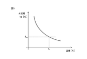
- FIG. 5 is a diagram illustrating the resistance temperature characteristics of the NTC thermistor.
- the NTC thermistor is an element whose resistance value decreases as the temperature rises.
- the combined resistance value of the NTC thermistors connected in series decreases as the temperature in the vicinity of at least one NTC thermistor rises.
- the resistance temperature characteristic shown in FIG. 5 shows the relationship between the temperature of a plurality of NTC thermistors connected in series and the combined resistance value.
- the temperature sensors 11-1 to 11-m are used in the determination process by the determination unit 13.
- the threshold value to be compared with the combined resistance value of m may be set as follows.
- the threshold value used in the determination process of the determination unit 13 in the second embodiment is referred to as a “second threshold value”.
- the failure detection device 1 In order to realize the failure detection device 1 according to the embodiment of the present disclosure with the temperature sensors 11-1 to 11-m composed of NTC thermistors, at least one switch among a plurality of switches 21-1 to 21-n is used.
- the combined resistance value of multiple NTC thermistors connected in series when an open failure occurs is the combined resistance of multiple NTC thermistors connected in series when all of the switches 21-1 to 21-n are normal. It is necessary to select an NTC thermistor that is less than the resistance value. For example, if each of the temperature sensors 11-1 to 11-m is configured with an NTC thermistor having the same temperature resistance value characteristics, the relationship between the above-mentioned combined resistance value at the time of open failure and the combined resistance value at the time of normal operation is obtained. It becomes easy to realize the failure detection device 1 that satisfies the above conditions.
- the heat resistant temperature of the switches 21-1 to 21-n, the heat resistant temperature of the substrate on which the switches 21-1 to 21-n are mounted, and the heat resistant temperature of the switches 21-1 to 21-n are arranged.
- one NTC thermistor temperature when it is determined that a failure has occurred.
- the second resistance value is obtained by adding a slight margin to the combined resistance value of the NTC thermistors (temperature sensors 11-1 to 11-m) connected in series when the temperature reaches.
- the determination unit 13 determines whether or not an open failure has occurred based on the comparison result between the second threshold value R th2 and the combined resistance value detected by the detection unit 12.
- the determination unit 13 at least NTC thermistors (temperature sensors 11-1 to 11-m). It is determined that an open failure that caused the decrease in the combined resistance value of 11-m) has occurred.
- the second threshold value R th2 may be stored in a rewritable storage unit (not shown) and rewritable by an external device, whereby the second threshold value R th2 is once set. However, it can be changed to an appropriate value as needed.
- FIG. 6 is a flowchart showing the operation flow of the failure detection device according to the second embodiment using the NTC thermistor as the temperature sensor.
- step S201 In a circuit in which a plurality of switches 21-1 to 21-n connected in parallel shown in FIG. 1 are provided on the current path 50 and the plurality of switches 21-1 to 21-n are driven in parallel, detection is performed in step S201.
- the unit 12 detects the combined resistance value of the temperature sensors 11-1 to 11-m, each of which is composed of an NTC thermistor.
- the data regarding the combined resistance value detected by the detection unit 12 is sent to the determination unit 13.
- step S202 the determination unit 13 compares the combined resistance value detected by the detection unit 12 with the second threshold value R th2, and determines whether or not the combined resistance value is lower than the second threshold value R th2.
- step S202 the synthesis if the resistance value is determined to have fallen below a second threshold value R th2 proceeds to step S203, if the combined resistance value is not determined to have fallen below a second threshold value R th2 returns to step S201 .
- the processes of steps S201 and S202 are repeatedly executed in a predetermined cycle.
- step S203 determines that at least one of the switches 21-1 to 21-n has failed.
- the failure determination result by the determination unit 13 may be displayed on the display unit, for example.
- the display unit include a single display device and a display device attached to a personal computer and a mobile terminal.
- the failure determination result by the determination unit 13 may be output by an audio device that emits a sound such as a voice, a speaker, a buzzer, or a chime. This allows the operator to know that at least one of the switches 21-1 to 21-n has failed. Therefore, the operator can take measures such as replacement or repair of the entire switch 21-1 to 21-n, or replacement or repair of the board or various parts.
- a plurality of switches 21-1 to 21-n connected in parallel as shown in FIG. 1 are provided based on the failure determination result by the determination unit 13.
- the machine having the circuit may be stopped in an emergency or operated to avoid an abnormality. Further, the determination result by the determination unit 13 may be recorded in the storage device, and the determination result may be used thereafter.
- the temperature sensors 11-1 to 11-m are electrically connected in series with each other, and the detection unit 12 detects the combined resistance value of the temperature sensors 11-1 to 11-m connected in series. Then, the determination unit 13 detected the occurrence of an open failure based on this combined resistance value.
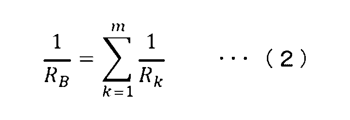
- temperature sensors 11-1 to 11-m are connected in parallel to each other via their respective terminals, and the detection unit 12 detects the combined resistance value of these parallel-connected temperature sensors 11-1 to 11-m. You may try to do it.
- the detection unit 12 for example calculates the combined resistance value R B according to equation 2.
- the determination unit 13 may detect an open failure on the basis of the combined resistance value R B.
- FIG. 7 is a perspective view illustrating a precharging circuit provided with a temperature sensor in the failure detection device according to the embodiment of the present disclosure.
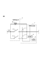
- FIG. 8 is a circuit diagram illustrating a precharging circuit provided with a temperature sensor in the failure detection device according to the embodiment of the present disclosure.
- FIGS. 7 and 8 as an example, a case where the precharging circuit 5 is provided with two switches will be described.
- the precharging circuit 5 provided in the motor drive device measures the inrush current that may occur when precharging the DC link capacitor provided between the DC output side of the converter circuit and the DC input side of the inverter circuit in the motor drive device. It is to prevent.
- the precharging circuit is provided on the DC output side or the AC input side of the converter circuit.
- the precharging circuit 5 has switches 21-1 and 21-2 and a precharging resistor 22 connected in parallel to the switches 21-1 and 21-2.
- switches 21-1 and 21-2 include relays and semiconductor switching elements. Since the switch 21 closes and a large current flows after the pre-charging is completed, the switch 21 is composed of a plurality of switches 21-1 and 21-2 connected in parallel. By closing multiple switches 21-1 and 21-2 connected in parallel at the same time, a large current can be distributed and flowed to each switch 21-1 and 21-2, and by opening them at the same time, a large current can be generated. It can be blocked.
- the switches 21-1 and 21-2 of the precharging circuit 5 and the precharging resistor 22 are mounted on the substrate 20.
- Various components 23 are further provided on the substrate 20. Examples of various parts 23 include, for example, a capacitor that is sensitive to heat. Temperature sensors 11-1 and 11-2 are provided in the vicinity of the switches 21-1 and 21-2, respectively. As an example of this modification, temperature sensors 11-1 and 11-2 may be provided in the vicinity of a heat-sensitive capacitor.
- FIG. 9 is a diagram illustrating a motor drive device including a failure detection device according to an embodiment of the present disclosure.
- the type of the motor 300 is not particularly limited, and may be, for example, an induction motor or a synchronous motor.
- the number of phases of the AC power supply 200 and the motor 300 is not particularly limited to this embodiment, and may be, for example, three-phase or single-phase.
- the AC power supply 200 and the motor 300 have three phases, respectively.
- Examples of the AC power supply 200 include a three-phase AC 400V power supply, a three-phase AC 200V power supply, a three-phase AC 600V power supply, and a single-phase AC 100V power supply.
- Machines provided with the motor 300 include, for example, machine tools, robots, forging machines, injection molding machines, industrial machines and the like.
- the motor drive device 100 includes a failure detection device 1, a converter circuit 2, a DC link capacitor 3, an inverter circuit 4, and a precharging circuit 5. Further, an electromagnetic contactor 6 is provided between the motor drive device 100 and the AC power supply 200.
- the failure detection device 1 is as described with reference to FIGS. 1 to 8.
- the converter circuit 2 converts the AC power input from the AC power supply 200 into DC power and outputs it to the DC link on the DC output side.
- the "DC link” may also be referred to as a "DC link unit", a “DC link”, a “DC link unit”, a “DC intermediate circuit”, or the like.
- the converter circuit 2 is composed of a three-phase bridge circuit when three-phase AC power is supplied from the AC power supply 200, and is composed of a single-phase bridge circuit when single-phase AC power is supplied from the AC power supply 200. In the illustrated example, since the AC power supply 200 is a three-phase AC power supply, the converter circuit 2 is composed of a three-phase bridge circuit.
- Examples of the converter circuit 2 include a diode rectifier, a 120-degree energization type rectifier, a PWM switching control type rectifier, and the like.
- the converter circuit 2 when it is a 120-degree energization type rectifier and a PWM switching control type rectifier, it is composed of a semiconductor switching element and a bridge circuit of a diode connected in antiparallel to the semiconductor switching element, from a host controller (not shown).
- Each switching element is on / off controlled according to the received drive command to perform power conversion in both AC and DC directions.
- examples of the switching element include FET, IGBT, thyristor, GTO, transistor, etc., but other semiconductor switching elements may be used.
- An electromagnetic contactor 6 is provided on the AC input side of the converter circuit 2.
- the magnetic contactor 6 opens and closes the current path of the AC input current from the AC power supply 200 to the converter circuit 2.
- the closing operation of forming the current path of the AC input current from the AC power supply 200 to the converter circuit 2 is realized by closing the contacts of the electromagnetic contactor 6, and the AC input current from the AC power supply 200 to the converter circuit 2 is closed.
- the opening operation for cutting off the current path is realized by opening the contacts of the electromagnetic contactor 6.
- an AC reactor, an AC line filter, or the like may be provided on the AC input side of the converter circuit 2, but the illustration is omitted here.
- a DC link capacitor 3 is provided on the DC link connecting the DC output side of the converter circuit 2 and the DC input side of the inverter circuit 4.
- the DC link capacitor 3 has a function of accumulating DC power used by the inverter circuit 4 to generate AC power and a function of suppressing the pulsation of the DC output of the converter circuit 2.
- Examples of the DC link capacitor 3 include, for example, an electrolytic capacitor and a film capacitor.
- the inverter circuit 4 is connected to the converter circuit 2 via the DC link, and converts the DC power in the DC link into AC power for driving the motor and outputs it.
- An example of the inverter circuit 4 is a PWM control type inverter including a rectifying element and a bridge circuit of a semiconductor switching element connected in antiparallel to the rectifying element. Examples of semiconductor switching elements include FETs, IGBTs, thyristors, GTOs, transistors, and the like, but other semiconductor elements may also be used.
- the inverter circuit 4 is configured as a three-phase bridge circuit when the motor 300 is a three-phase AC motor, and is configured as a single-phase bridge circuit when the motor 300 is a single-phase AC motor.
- the inverter circuit 4 is composed of a three-phase bridge circuit.
- the inverter circuit 4 converts the DC power in the DC link into AC power for driving the motor by PWM-controlling the on / off operation of the internal semiconductor switching element based on the command of the host control device (not shown). Output.
- the motor 300 controls the speed, torque, or rotor position based on the AC power supplied from the inverter circuit 4.
- the inverter circuit 4 can also convert the AC power regenerated by the motor 300 into DC power and return it to the DC link on the DC side by appropriately PWM-controlling the on / off operation of the switching element.
- the pre-charging circuit (initial charging circuit) 5 is used. It will be provided.
- the precharging circuit 5 is provided on the DC output side or the AC input side of the converter circuit 2. In the example shown in FIG. 9, the precharging circuit 5 is provided on the DC output side of the converter circuit 2 as an example.
- the pre-charging circuit 5 has switches 21-1 and 21-2 and a pre-charging resistor 22 connected in parallel to these switches 21-1 and 21-2.
- switches 21-1 and 21-2 include relays and semiconductor switching elements.
- two switches 21-1 and 21-2 are connected in parallel as an example, but three or more switches may be connected in parallel.
- the switches 21-1 and 21-2 follow the open command received from the host control device (not shown). Open (off) at the same time. Since the switches 21-1 and 21-2 are maintained in the open state during the precharging period, the current output from the converter circuit 2 flows into the DC link capacitor 3 as a charging current via the precharging resistor 22, and is DC-linked. The capacitor 3 is charged (pre-charged). As described above, during the precharging period, the current output from the converter circuit 2 flows through the precharging resistor 22, so that the generation of inrush current can be prevented.
- the switches 21-1 and 21-2 are simultaneously closed (on) according to the close command received from the host controller (not shown). After the precharging is completed, the driving of the motor 300 is started, and the current output from the converter circuit 2 flows toward the inverter circuit 4 and the DC link capacitor 3 through the closed switches 21-1 and 21-2.
- Temperature sensors 11-1 and 11-2 are provided in the vicinity of the switches 21-1 and 21-2 on the board on which the switches 21-1 and 21-2 are mounted.
- the failure detection device 1 determines whether or not there is a switch in which an open failure has occurred in the plurality of switches 21-1 and 21-2 in the precharging circuit 5.
- the switches 21-1 and 21-2 are open (off) during the precharging period, no current flows through the switches 21-1 and 21-2. Therefore, the temperature change in the vicinity of the switches 21-1 to 21-n and the substrate on which these switches 21-1 to 21-n are mounted is small, and the combined resistance value detected by the detection unit 12 in the failure detection device 1 is small. There is almost no change.
- the detection unit 12 detects the combined resistance values of the temperature sensors 11-1 and 11-2, and the determination unit 13 executes the failure determination process based on the combined resistance values detected by the detection unit 12. As described with reference to FIGS. 3 and 4, when the temperature sensors 11-1 and 11-2 are composed of PTC thermistors, the first threshold value R th1 is normal for all switches 21-1 and 21-2.
- the determination unit 13 Since the value is set to be larger than the combined resistance value in a certain case, the determination unit 13 does not determine that the combined resistance value detected by the detection unit 12 exceeds the first threshold value R th1 , and therefore an open failure occurs. Is not determined.
- the second threshold value R th2 As described with reference to FIGS. 5 and 6, when the temperature sensors 11-1 and 11-2 are composed of NTC thermistors, the second threshold value R th2 is normal for all switches 21-1 and 21-2. Since the value is set to be smaller than the combined resistance value in a certain case, the determination unit 13 does not determine that the combined resistance value detected by the detection unit 12 is below the second threshold value R th2 , and therefore an open failure occurs. Is not determined.
- the host controller (not shown) outputs a close command to switches 21-1 and 21-2.
- the determination unit 13 has a second threshold value of the combined resistance value detected by the detection unit 12. It is not determined that the temperature is below R th2, and therefore it is not determined that an open failure has occurred.
- the determination unit 13 has a second threshold value of the combined resistance value detected by the detection unit 12. It is determined that the temperature is lower than R th2, and therefore it is determined that an open failure has occurred.
- the failure detection device 1 can detect that an open failure has occurred in at least one of the precharging circuits 5 having a plurality of switches 21-1 and 21-2 driven in parallel.
- the failure determination result by the determination unit 13 in the failure detection device 1 may be displayed on the display unit, for example, or may be output by an audio device that emits a sound such as a voice, a speaker, a buzzer, or a chime. good. Further, based on the failure determination result by the determination unit 13 in the failure detection device 1, the motor drive device 100 may be stopped urgently, or the machine provided with the motor drive device 100 may be made to perform an abnormality avoidance operation. ..
- the failure detection device 1 is not limited to the precharging circuit 5 as described above, and can detect the occurrence of an open failure in a circuit having a plurality of switches driven in parallel.
- the electromagnetic contactor 6 when the AC power supply 200 has three phases as shown in FIG. 9, the electromagnetic contactor 6 also has contact circuits for three phases correspondingly, and these contact circuits are driven in parallel.
- the contacts in the electromagnetic contactor 6 are formed. It is possible to configure a failure detection device 1 capable of detecting the occurrence of an open failure between them.
- a dynamic brake circuit (not shown) for stopping the motor 300 may be provided in the motor drive device 100 shown in FIG.
- the dynamic brake circuit includes a relay provided between the input terminals of the motor 300 and a dynamic brake resistor connected in series with the relay.
- the dynamic brake When applying the dynamic brake, the supply of drive power to the motor 300 is cut off, and then the relay is closed to short-circuit between the input terminals of the motor 300 (between the phases of the motor windings). Even if the motor 300 is electrically disconnected from the power supply, a field magnetic flux exists, and the motor 300 rotating due to coasting acts as a generator, so that the current generated by this acts as a dynamic brake via a closed relay. It flows into the resistor and a deceleration torque is generated in the motor 300.
- a switch in the dynamic brake circuit is provided by providing temperature sensors in the vicinity of each of the relays in the dynamic brake circuit, electrically connecting these temperature sensors in series with each other, and further configuring the detection unit 12 and the determination unit 13 described above. It is possible to configure a failure detection device 1 capable of detecting the occurrence of an open failure.
- the inverter circuit 4 in the motor drive device 100 shown in FIG. 9 is provided with a plurality of semiconductor switching elements.
- the converter circuit 2 is a 120-degree energization type rectifier and a PWM switching control type rectifier
- a plurality of semiconductor switching elements are also provided in the converter circuit 2.
- the inside of the inverter circuit 4 and the converter circuit 2 can be configured. It is possible to configure a failure detection device 1 capable of detecting the occurrence of an open failure of the semiconductor switching element inside.
Landscapes
- Physics & Mathematics (AREA)
- General Physics & Mathematics (AREA)
- Inverter Devices (AREA)
- Protection Of Static Devices (AREA)
- Emergency Protection Circuit Devices (AREA)
Abstract
Description

2 コンバータ回路
3 DCリンクコンデンサ
4 インバータ回路
5 予備充電回路
6 電磁接触器
11、11-1~11-m 温度センサ
12 検出部
13 判定部
20 基板
21、21-1~21-n スイッチ
22 予備充電抵抗
23 各種部品
100 モータ駆動装置
200 交流電源
300 モータ
Claims (7)
- 電流経路上における導通と非導通とが選択的に切り替えられるスイッチの故障を検出する故障検出装置であって、
温度変化に応じて端子間の抵抗値が変化する温度センサであって、互いに並列接続された少なくとも2つの前記スイッチの近傍に設けられ、互いに電気的に直列接続された少なくとも2つの温度センサと、
前記少なくとも2つの温度センサの合成抵抗値を検出する検出部と、
前記合成抵抗値に基づき、前記スイッチのうち少なくとも1つが故障したと判定する判定部と、
を備える、故障検出装置。 - 前記少なくとも2つの温度センサの各々は、温度上昇に伴い抵抗値が増加するPTCサーミスタであり、
前記判定部は、前記合成抵抗値が予め規定された第1の閾値を上回った場合、前記スイッチのうち少なくとも1つが故障したと判定する、請求項1に記載の故障検出装置。 - 前記少なくとも2つの温度センサの各々は、温度上昇に伴い抵抗値が低下するNTCサーミスタであり、
前記判定部は、前記合成抵抗値が予め規定された第2の閾値を下回った場合、前記スイッチのうち少なくとも1つが故障したと判定する、請求項1に記載の故障検出装置。 - 前記スイッチは、リレーである、請求項1~3のいずれか一項に記載の故障検出装置。
- 前記スイッチは、半導体スイッチング素子である、請求項1~3のいずれか一項に記載の故障検出装置。
- 前記スイッチは、電磁接触器である、請求項1~3のいずれか一項に記載の故障検出装置。
- 請求項1~6のいずれか一項に記載の故障検出装置と、
交流電源から入力された交流電力を直流電力に変換して出力するコンバータ回路と、
前記コンバータ回路の直流出力側であるDCリンクに設けられるDCリンクコンデンサと、
前記DCリンクにおける直流電力を、モータ駆動のための交流電力に変換して出力するインバータ回路と、
前記スイッチと前記スイッチに並列接続された予備充電抵抗とを有し前記DCリンクコンデンサの予備充電時における突入電流を防止するための予備充電回路と、
を備える、モータ駆動装置。
Priority Applications (4)
| Application Number | Priority Date | Filing Date | Title |
|---|---|---|---|
| US17/999,052 US12184057B2 (en) | 2020-05-18 | 2021-05-14 | Failure detection device that detects failure of parallel-driven switch, and motor drive device |
| JP2022524449A JP7436650B2 (ja) | 2020-05-18 | 2021-05-14 | 並列駆動されるスイッチの故障を検出する故障検出装置及びモータ駆動装置 |
| CN202180032356.1A CN115485945B (zh) | 2020-05-18 | 2021-05-14 | 检测并联驱动的开关的故障的故障检测装置及电动机驱动装置 |
| DE112021001347.5T DE112021001347T5 (de) | 2020-05-18 | 2021-05-14 | Fehlererkennungsvorrichtung, die den ausfall eines parallelgesteuerten schalters erkennt, und motorantriebsvorrichtung |
Applications Claiming Priority (2)
| Application Number | Priority Date | Filing Date | Title |
|---|---|---|---|
| JP2020086839 | 2020-05-18 | ||
| JP2020-086839 | 2020-05-18 |
Publications (1)
| Publication Number | Publication Date |
|---|---|
| WO2021235367A1 true WO2021235367A1 (ja) | 2021-11-25 |
Family
ID=78709034
Family Applications (1)
| Application Number | Title | Priority Date | Filing Date |
|---|---|---|---|
| PCT/JP2021/018488 Ceased WO2021235367A1 (ja) | 2020-05-18 | 2021-05-14 | 並列駆動されるスイッチの故障を検出する故障検出装置及びモータ駆動装置 |
Country Status (5)
| Country | Link |
|---|---|
| US (1) | US12184057B2 (ja) |
| JP (1) | JP7436650B2 (ja) |
| CN (1) | CN115485945B (ja) |
| DE (1) | DE112021001347T5 (ja) |
| WO (1) | WO2021235367A1 (ja) |
Cited By (2)
| Publication number | Priority date | Publication date | Assignee | Title |
|---|---|---|---|---|
| WO2024116752A1 (ja) * | 2022-11-29 | 2024-06-06 | 株式会社オートネットワーク技術研究所 | 車載用電源装置 |
| EP4382928A1 (en) * | 2022-12-09 | 2024-06-12 | ABB E-mobility B.V. | Method for detecting a stuck ac switch in a converter |
Families Citing this family (4)
| Publication number | Priority date | Publication date | Assignee | Title |
|---|---|---|---|---|
| TWI822224B (zh) * | 2022-08-03 | 2023-11-11 | 飛捷科技股份有限公司 | 攝影裝置、攝影裝置加熱模組與方法 |
| EP4489277A4 (en) * | 2023-05-17 | 2025-09-03 | Huawei Digital Power Tech Co Ltd | POWER CONVERTER AND METHOD FOR DETERMINING AN ABNORMAL TERMINAL OF A POWER CONVERTER |
| US20250001994A1 (en) * | 2023-06-29 | 2025-01-02 | Oshkosh Corporation | Safety junction box |
| US12504475B2 (en) * | 2023-07-10 | 2025-12-23 | Hamilton Sundstrand Corporation | Fail open detection |
Citations (2)
| Publication number | Priority date | Publication date | Assignee | Title |
|---|---|---|---|---|
| JP2013211950A (ja) * | 2012-03-30 | 2013-10-10 | Hitachi Industrial Equipment Systems Co Ltd | 電力変換装置 |
| KR20170099287A (ko) * | 2016-02-23 | 2017-08-31 | 엘에스산전 주식회사 | 배터리 디스커넥트 유닛의 릴레이 감시 장치 |
Family Cites Families (5)
| Publication number | Priority date | Publication date | Assignee | Title |
|---|---|---|---|---|
| JPS5350953A (en) | 1976-10-20 | 1978-05-09 | Casio Comput Co Ltd | Comparison/array system for variable length information |
| JPH0643186A (ja) * | 1992-07-22 | 1994-02-18 | Yokogawa Electric Corp | 電流分流装置 |
| US5627738A (en) * | 1995-05-19 | 1997-05-06 | Eni, A Division Of Astec America, Inc. | Low cost, high reliability soft start arrangement |
| US6094013A (en) * | 1998-07-24 | 2000-07-25 | Siemens Aktiengesellschaft | Circuit arrangement for limiting the current at make for a transformer |
| JP6680231B2 (ja) * | 2017-01-27 | 2020-04-15 | 株式会社デンソー | 回転電機制御装置 |
-
2021
- 2021-05-14 WO PCT/JP2021/018488 patent/WO2021235367A1/ja not_active Ceased
- 2021-05-14 DE DE112021001347.5T patent/DE112021001347T5/de active Pending
- 2021-05-14 CN CN202180032356.1A patent/CN115485945B/zh active Active
- 2021-05-14 JP JP2022524449A patent/JP7436650B2/ja active Active
- 2021-05-14 US US17/999,052 patent/US12184057B2/en active Active
Patent Citations (2)
| Publication number | Priority date | Publication date | Assignee | Title |
|---|---|---|---|---|
| JP2013211950A (ja) * | 2012-03-30 | 2013-10-10 | Hitachi Industrial Equipment Systems Co Ltd | 電力変換装置 |
| KR20170099287A (ko) * | 2016-02-23 | 2017-08-31 | 엘에스산전 주식회사 | 배터리 디스커넥트 유닛의 릴레이 감시 장치 |
Cited By (2)
| Publication number | Priority date | Publication date | Assignee | Title |
|---|---|---|---|---|
| WO2024116752A1 (ja) * | 2022-11-29 | 2024-06-06 | 株式会社オートネットワーク技術研究所 | 車載用電源装置 |
| EP4382928A1 (en) * | 2022-12-09 | 2024-06-12 | ABB E-mobility B.V. | Method for detecting a stuck ac switch in a converter |
Also Published As
| Publication number | Publication date |
|---|---|
| US20230178976A1 (en) | 2023-06-08 |
| CN115485945B (zh) | 2025-03-04 |
| JPWO2021235367A1 (ja) | 2021-11-25 |
| DE112021001347T5 (de) | 2022-12-15 |
| US12184057B2 (en) | 2024-12-31 |
| CN115485945A (zh) | 2022-12-16 |
| JP7436650B2 (ja) | 2024-02-21 |
Similar Documents
| Publication | Publication Date | Title |
|---|---|---|
| JP7436650B2 (ja) | 並列駆動されるスイッチの故障を検出する故障検出装置及びモータ駆動装置 | |
| US10090795B2 (en) | Motor drive having function of protecting dynamic braking circuit | |
| JP6694006B2 (ja) | Dcリンクコンデンサの短絡判定部を有するモータ駆動装置 | |
| JP6200457B2 (ja) | 初期充電回路の異常発熱を検出する手段を有するモータ駆動装置 | |
| JP5630474B2 (ja) | インバータ | |
| KR100998277B1 (ko) | 구동회로용 오동작판정장치와 이를 포함한 구동유닛 및구동회로의 오동작판정방법 | |
| US10651758B2 (en) | Motor drive apparatus including short-circuit judgment unit for capacitor of DC link unit | |
| CN112909895B (zh) | 马达驱动装置 | |
| JP6285475B2 (ja) | 放電機能を有するモータ駆動装置 | |
| US20200052642A1 (en) | Motor drive apparatus having input power supply voltage adjustment function | |
| JP6215982B2 (ja) | 初期充電部を有するモータ駆動装置 | |
| JP2015216781A (ja) | 電動車両 | |
| CN111010051A (zh) | 电动机驱动装置 | |
| JP6616437B2 (ja) | Dcリンク部のコンデンサの短絡判定部を有するモータ駆動装置 | |
| JP7564356B2 (ja) | 温度推定装置及びコンバータシステム | |
| JP2015136217A (ja) | インバータ制御装置 | |
| JP7502020B2 (ja) | 保護機構を有するモータ駆動装置 | |
| JP6957383B2 (ja) | 電力変換装置 | |
| JP2004112929A (ja) | 交流−直流変換装置 | |
| JP7324140B2 (ja) | 予備充電回路を有するモータ駆動装置 | |
| CN112511071B (zh) | 功率转换装置的控制装置 | |
| JP2019138656A (ja) | Dcリンク部のコンデンサの短絡判定部を有するモータ駆動装置 | |
| US20240162704A1 (en) | Inrush current suppression circuit, converter system, and motor drive device | |
| JP5983485B2 (ja) | オルタネータおよびレクチファイヤ | |
| JP5861602B2 (ja) | 電力変換システム |
Legal Events
| Date | Code | Title | Description |
|---|---|---|---|
| 121 | Ep: the epo has been informed by wipo that ep was designated in this application |
Ref document number: 21808417 Country of ref document: EP Kind code of ref document: A1 |
|
| ENP | Entry into the national phase |
Ref document number: 2022524449 Country of ref document: JP Kind code of ref document: A |
|
| 122 | Ep: pct application non-entry in european phase |
Ref document number: 21808417 Country of ref document: EP Kind code of ref document: A1 |
|
| WWG | Wipo information: grant in national office |
Ref document number: 202180032356.1 Country of ref document: CN |