WO2021234960A1 - 空気調和機の室外機 - Google Patents
空気調和機の室外機 Download PDFInfo
- Publication number
- WO2021234960A1 WO2021234960A1 PCT/JP2020/020353 JP2020020353W WO2021234960A1 WO 2021234960 A1 WO2021234960 A1 WO 2021234960A1 JP 2020020353 W JP2020020353 W JP 2020020353W WO 2021234960 A1 WO2021234960 A1 WO 2021234960A1
- Authority
- WO
- WIPO (PCT)
- Prior art keywords
- heat exchanger
- housing
- air conditioner
- outdoor
- refrigerant
- Prior art date
- Legal status (The legal status is an assumption and is not a legal conclusion. Google has not performed a legal analysis and makes no representation as to the accuracy of the status listed.)
- Ceased
Links
Images



Classifications
-
- F—MECHANICAL ENGINEERING; LIGHTING; HEATING; WEAPONS; BLASTING
- F24—HEATING; RANGES; VENTILATING
- F24F—AIR-CONDITIONING; AIR-HUMIDIFICATION; VENTILATION; USE OF AIR CURRENTS FOR SCREENING
- F24F1/00—Room units for air-conditioning, e.g. separate or self-contained units or units receiving primary air from a central station
- F24F1/06—Separate outdoor units, e.g. outdoor unit to be linked to a separate room comprising a compressor and a heat exchanger
- F24F1/14—Heat exchangers specially adapted for separate outdoor units
- F24F1/18—Heat exchangers specially adapted for separate outdoor units characterised by their shape
Definitions
- the present disclosure relates to an outdoor unit of an air conditioner provided with an outdoor heat exchanger having a plurality of flat tubes and fins provided between adjacent flat tubes.
- an outdoor unit of an air conditioner a top-flow type outdoor unit in which an air outlet is formed on the upper surface of a housing and an outdoor blower is installed directly below the air outlet is known.
- Patent Document 1 air conditioning having a structure in which components such as an outdoor heat exchanger, a blower fan, a compressor, and an electrical component unit are housed inside a rectangular parallelepiped outdoor unit body having air suction ports on four side surfaces. The outdoor unit of the machine is disclosed.
- the outdoor heat exchanger in Patent Document 1 is a cross-fin coil type in which a heat transfer tube penetrates a plurality of fins arranged in parallel in the horizontal direction in the horizontal direction and meanders in the vertical direction.
- This outdoor heat exchanger faces four side surfaces of the four corners of the outdoor unit main body except for one corner, and is bent in a substantially quadrangular shape along the four side surfaces.
- the outdoor heat exchanger has an opening provided along the vertical direction between the edge portion arranged on the front side and the edge portion arranged on the left side surface side. The opening is divided into two by a support column arranged on the left front side.
- An electrical component unit is provided in the substantially upper half of the opening.
- the electrical component unit is fixed to the outdoor unit body with a joining member such as a bolt.
- the opening is closed by a side panel detachably attached to the outdoor unit main body in a state where the electrical component unit is fixed to the outdoor unit main body.
- the present disclosure has been made in order to solve the above-mentioned problems, the maintenance of the components installed inside the housing can be easily performed, and the air sucked into the heat exchanger in the vicinity of the blower can be easily performed. It is an object of the present invention to provide an outdoor unit of an air conditioner capable of making the wind speed distribution of the air conditioner uniform.
- the outdoor unit of the air conditioner according to the present disclosure includes a rectangular housing and a heat exchanger provided along the side surface of the housing, and the heat exchanger is a refrigerant flow flowing in the vertical direction.
- a path is formed, and a plurality of flat tubes arranged in parallel at intervals from each other, a plurality of fins provided between the adjacent flat tubes, and an upper end portion of each of the plurality of flat tubes are connected. It has an upper header and a lower header to which the lower ends of each of the plurality of flat tubes are connected, and at least one of the four sides of the housing has the upper side portion.
- a heat exchanger is arranged, and the lower part of the heat exchanger is an opening communicating with the inside, and the heat exchanger is arranged on the other side surface from the upper part to the lower part of the housing. It is something that is.
- a heat exchanger is arranged on the upper side portion of at least one side surface of the four side surfaces of the housing, and the lower portion of the heat exchanger communicates with the inside. Since it is an opening, the inside of the housing can be accessed by using the opening, and maintenance of the constituent members can be easily performed. Further, since the heat exchangers are arranged on the upper side of the four side surfaces of the housing, the wind speed distribution of the air sucked into the heat exchanger can be made uniform in the vicinity of the blower.
- FIG. 1 is a refrigerant circuit diagram of an air conditioner according to the present embodiment.
- the outdoor unit 100 of the air conditioner 300 constitutes the air conditioner 300 together with the indoor unit 200 that performs indoor air conditioning.
- the air conditioner 300 connects the compressor 101, the flow path switching means 102, the indoor heat exchanger 201, the expansion mechanism 103, and the outdoor heat exchanger 104 with a refrigerant pipe 105 to circulate the refrigerant. It has a circuit.
- the outdoor unit 100 includes a compressor 101, a flow path switching means 102, an expansion mechanism 103, and an outdoor heat exchanger 104.
- the indoor unit 200 includes an indoor heat exchanger 201.
- the air conditioner 300 is not limited to the illustrated components, and may include other components.
- the compressor 101 compresses the sucked refrigerant and discharges it in a high temperature and high pressure state.
- the compressor 101 is a positive displacement compressor having a configuration in which the operating capacity (frequency) can be changed and is driven by a motor controlled by an inverter.
- the flow path switching means 102 is a four-way valve as an example, and has a function of switching the flow path of the refrigerant.
- the flow path switching means 102 connects the refrigerant discharge side of the compressor 101 and the gas side of the outdoor heat exchanger 104 during the cooling operation, and also connects the refrigerant suction side of the compressor 101 and the gas side of the indoor heat exchanger 201. Switch the refrigerant flow path so as to connect with.
- the flow path switching means 102 connects the refrigerant discharge side of the compressor 101 and the gas side of the indoor heat exchanger 201 during the heating operation, and connects the refrigerant suction side of the compressor 101 and the outdoor heat exchanger 104. Switch the refrigerant flow path so as to connect to the gas side.
- the flow path switching means 102 may be configured by combining a two-way valve or a three-way valve.
- the indoor heat exchanger 201 functions as an evaporator during the cooling operation, and causes heat exchange between the refrigerant flowing out from the expansion mechanism 103 and the air. Further, the indoor heat exchanger 201 functions as a condenser during the heating operation, and causes heat exchange between the refrigerant discharged from the compressor 101 and the air. The indoor heat exchanger 201 sucks indoor air by an indoor blower and supplies the air that has exchanged heat with the refrigerant into the room.
- the expansion mechanism 103 decompresses and expands the refrigerant flowing in the refrigerant circuit, and is composed of an electronic expansion valve whose opening degree is variably controlled as an example.
- the outdoor heat exchanger 104 functions as a condenser during the cooling operation, and causes heat exchange between the refrigerant discharged from the compressor 101 and the air. Further, the outdoor heat exchanger 104 functions as an evaporator during the heating operation, and causes heat exchange between the refrigerant flowing out from the expansion mechanism 103 and the air. The outdoor heat exchanger 104 sucks in the outdoor air by the outdoor blower and discharges the air that has exchanged heat with the refrigerant to the outside.
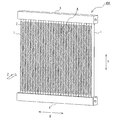
- FIG. 2 is a perspective view showing a heat exchanger of the outdoor unit of the air conditioner according to the present embodiment.
- FIG. 3 is a perspective view of the cross section of the portion A shown in FIG. 2 as viewed from above.
- a plurality of flat pipes 1 in which a refrigerant flow path 10 flowing in the vertical direction Y is formed and arranged in parallel at intervals from each other and adjacent flat pipes 1 are formed.
- a plurality of fins 2 provided between the tubes 1, an upper header 3 to which the upper end portions of the plurality of flat tubes 1 are connected, and a lower header 4 to which the lower end portions of the plurality of flat tubes 1 are connected to each other. And have.
- the flat tube 1 is made of, for example, aluminum.
- the flat tubes 1 are arranged in parallel at intervals in the left-right direction X so as to be orthogonal to the flow direction Z of the air flow. Further, the flat tube 1 is arranged so that the flow direction Z of the air flow and the flat surface are substantially parallel to each other.
- a plurality of refrigerant flow paths 10 in which the refrigerant flows in the vertical direction Y are formed in parallel inside the flat tube 1 along the flow direction Z of the air flow.
- the vertical direction Y includes not only the vertical direction but also a state of being tilted with respect to the vertical direction.
- the left-right direction X includes not only the horizontal direction but also a state of being tilted with respect to the horizontal direction.
- the fin 2 is made of aluminum, for example, and is a member that transfers the heat of the refrigerant flowing through the flat tube 1.
- the fin 2 is a corrugated fin formed by bending a thin plate in a wavy shape.
- the fins 2 are provided between two flat tubes 1 adjacent to each other among the plurality of flat tubes 1.
- the bent apex of the fin 2 is joined to the flat surface of either of the two flat tubes 1.
- the space between the fin 2 and the flat tube 1 is a ventilation path through which air flows.
- the fin 2 may be configured to have a drain hole, a louver, or the like for draining condensed water on each slope.
- the fin 2 is not limited to the corrugated fin, and may be, for example, a plate fin.
- the upper header 3 is connected to the upper end of each of the plurality of flat pipes 1 and is connected to the flow path switching means 102 via the refrigerant pipe 105.
- the upper header 3 is made of, for example, aluminum.
- the upper header 3 distributes the gas refrigerant flowing from the refrigerant pipe 105 to each flat pipe 1 when the outdoor heat exchanger 104 acts as a condenser. Further, the upper header 3 causes the gas refrigerant merged from the flat pipe 1 to flow out to the refrigerant pipe 105 when the outdoor heat exchanger 104 acts as an evaporator.
- the lower header 4 is connected to the lower ends of each of the plurality of flat pipes 1 and is connected to the expansion mechanism 103 via the refrigerant pipe 105.
- the lower header 4 is made of, for example, aluminum.
- the lower header 4 causes the liquid refrigerant merged from the flat pipe 1 to flow out to the refrigerant pipe 105 when the outdoor heat exchanger 104 acts as a condenser. Further, the lower header 4 distributes the gas-liquid two-phase refrigerant flowing from the refrigerant pipe 105 to each flat pipe 1 when the outdoor heat exchanger 104 acts as an evaporator.
- the high-temperature and high-pressure gas refrigerant discharged from the compressor 101 passes through the flow path switching means 102, flows to the outdoor heat exchanger 104, and exchanges heat with air to form a condensed liquid.
- the condensed liquefied refrigerant is decompressed by the expansion mechanism 103 to become a low-pressure gas-liquid two-phase refrigerant, which flows to the indoor heat exchanger 201 and exchanges heat with air to be gasified.
- the gasified refrigerant passes through the flow path switching means 102 and is sucked into the compressor 101.
- the high-temperature and high-pressure gas refrigerant discharged from the compressor 101 passes through the flow path switching means 102, flows to the indoor heat exchanger 201, exchanges heat with air, and becomes a condensed liquid.
- the condensed liquefied refrigerant is decompressed by the expansion mechanism 103 to become a low-pressure gas-liquid two-phase refrigerant, which flows to the outdoor heat exchanger 104 and exchanges heat with air to be gasified.
- the gasified refrigerant passes through the flow path switching means 102 and is sucked into the compressor 101.
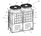
- FIG. 4 is a perspective view showing the appearance of the outdoor unit of the air conditioner according to the present embodiment.
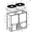
- FIG. 5 is a perspective view showing the internal structure of the outdoor unit of the air conditioner according to the present embodiment.
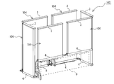
- FIG. 6 is a perspective view showing a state in which the heat exchanger of the outdoor unit of the air conditioner according to the present embodiment is arranged along the side surface of the housing.
- FIG. 7 is a perspective view showing a heat exchanger of the outdoor unit of the air conditioner according to the present embodiment, in which adjacent heat exchangers are connected to each other by a connecting member.
- FIG. 8 is a cross-sectional view showing in a plane a state in which the heat exchangers of the outdoor unit of the air conditioner according to the present embodiment are connected to each other by connecting members.
- the outdoor unit 100 of the air conditioner 300 is a top-flow type outdoor unit in which an air outlet 54 is formed on the upper surface of the housing 5 and an outdoor blower is provided at a position directly below the air outlet 54.
- the outdoor unit 100 of the air conditioner 300 has, for example, a compressor 101, a flow path switching means 102, an expansion mechanism 103, and an outdoor heat exchanger inside the housing 5 forming the outer shell. It is configured to house 104, an outdoor blower, a control device, and the like.
- FIG. 5 collectively shows the compressor 101, the flow path switching means 102, the expansion mechanism 103, and the control device as constituent members 106.
- the housing 5 includes a bottom plate 50 provided on the bottom surface, and a frame material 51 extending upward from the corners and edges of the bottom plate 50.
- the housing 5 has a rectangular shape in a plan view and has openings on four side surfaces surrounded by a frame material 51 arranged at the corners.
- the opening is an air suction port 53 for taking in air inside the housing 5, and an outdoor heat exchanger 104 is arranged along each air suction port 53.
- components 106 such as a compressor 101, a flow path switching means 102, an expansion mechanism 103, and a control device are installed below the inside of the housing 5.
- the outdoor heat exchanger 104 has a flat plate shape and is independently provided on each of the four side surfaces of the housing 5.
- Two outdoor heat exchangers 104 are arranged side by side along the circumferential direction of the housing 5 on the front side surface, and the lower header 4 is connected by a pipe.
- two outdoor heat exchangers 104 are arranged side by side along the circumferential direction of the housing 5 on the side surface on the back side, and the lower header 4 is connected by a pipe.
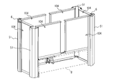
- the outdoor heat exchanger 104 is arranged on the upper side portion on the front side surface, and the lower part of the outdoor heat exchanger 104 is inside. It is an opening 8 that communicates with. Further, among the four side surfaces of the housing 5, the outdoor heat exchanger 104 is arranged from the upper portion to the lower portion on the left side surface, the right side surface, and the back surface side surface. As shown in FIG. 4, the opening 8 on the front side is closed by the side panel 52 which is a design sheet metal. The left and right side edges of the side panel 52 are fixed to the frame material 51 with fastening members such as screws, and the lower edge portion is fixed to the bottom plate 50 with fastening members such as screws.
- the opening 8 has a minimum size that allows the operator to perform maintenance on the constituent member 106. This is because if the opening 8 is too large, a wasteful portion is generated in heat exchange, and if the opening 8 is too small, the operator cannot sufficiently perform the work.
- the configuration in which the opening 8 communicating with the inside of the housing 5 is formed on the side surface on the front side is not limited to this.
- the outdoor heat exchanger 104 is arranged in the upper side portion, and the lower portion of the outdoor heat exchanger 104 and the opening 8 communicating with the inside.
- the outdoor heat exchanger 104 may be arranged from the upper portion to the lower portion of the housing 5 on other side surfaces including the front side surface.
- the outdoor heat exchanger 104 is arranged on the upper side portion, and the lower portion of the outdoor heat exchanger 104 is an opening 8 communicating with the inside. It may be configured as such.
- one end edge of the outdoor heat exchanger 104 on the front side and the outdoor heat exchanger 104 on the right side side is connected to each other by a connecting member 6.
- the other end edge of the outdoor heat exchanger 104 on the front side and the other end edge of the outdoor heat exchanger 104 on the right side are joined to the frame material 51 in the vicinity by a joining member 7 such as a bolt.
- one end edge of the outdoor heat exchanger 104 on the back side and one end edge of the outdoor heat exchanger 104 on the left side surface are connected members 6.
- the other end edge of the outdoor heat exchanger 104 on the back surface side and the other end edge of the outdoor heat exchanger 104 on the left side surface side are joined to the frame material 51 in the vicinity by a joining member 7 such as a bolt.
- the connecting member 6 has a U-shaped sheet metal 60 and a joining member 61 such as a bolt.
- the U-shaped sheet metal 60 is arranged inside the frame material 51, and both end edges of the U-shape are applied to each end edge of the adjacent outdoor heat exchanger 104.
- the joining member 61 joins the sheet metal 60, the outdoor heat exchanger 104, and the frame material 51.
- the connecting member 6 is not limited to the illustrated configuration, and may have any other configuration as long as the outdoor heat exchangers 104 adjacent to each other in the circumferential direction of the housing 5 can be connected to each other.
- the method of fixing the outdoor heat exchanger 104 to the frame material 51 is not limited to the above configuration.
- the flat plate-shaped outdoor heat exchanger 104 may be directly joined to the frame material 51 without connecting the adjacent outdoor heat exchangers 104 to each other by the connecting member 6.
- the shape of the outdoor heat exchanger 104 is not limited to the flat plate shape, and may be, for example, an L-shape, a U-shape, an O-shape, or the like.
- the adjacent outdoor heat exchangers 104 may be connected to each other by the connecting member 6, or each outdoor heat exchanger 104 may be joined to the frame material 51 without being connected.
- an air outlet 54 is formed on the upper surface of the housing 5, and an outdoor blower is installed at a position directly below the air outlet 54.
- the air outlet 54 is provided with a bell mouth 55 that surrounds the outdoor blower.
- a fan guard 54a is attached to the air outlet 54.
- the outdoor blower is composed of, for example, a propeller fan or the like, and is driven by a blower motor. By driving the outdoor blower, the air sucked into the housing 5 from the air suction port 53 passes through the outdoor heat exchanger 104, exchanges heat with the refrigerant, and then is exhausted from the air outlet 54 via the outdoor blower.
- Two outdoor blowers may be provided as shown in the figure, or one may be provided although not shown.
- the outdoor heat exchanger has a plurality of fins arranged in parallel at intervals from each other and a plurality of transmissions meandering in the vertical direction Y penetrating the plurality of fins in the horizontal direction.
- a cross-fin type heat exchanger equipped with a heat tube is known.
- the cross-fin type heat exchanger is provided with a plurality of refrigerant paths composed of one or a plurality of heat transfer tubes.
- headers are vertically arranged at both left and right ends of the heat transfer tube, and the refrigerant is distributed to each path by the headers.
- the refrigerant flowing into each path becomes non-uniform.
- the refrigerant tends to flow to the lower part where the wind speed is low, and the amount of the refrigerant to the upper position where the wind speed is high is small, so that efficient heat exchange may not be possible.
- One way to improve the refrigerant distribution is to provide a capillary tube between the header and each path.
- the outdoor heat exchanger 104 of the present embodiment since the lower header 4 is arranged horizontally, it is not affected by gravity when the refrigerant is distributed to each flat pipe 1. That is, in this outdoor heat exchanger 104, the refrigerant flowing in the pipe of the lower header 4 can be uniformly distributed to each flat pipe 1 without using a capillary tube or the like. Therefore, the heat exchange efficiency can be improved, and it becomes easy to design a unit in which a plurality of heat exchangers having different heights are combined.
- the outdoor unit 100 of the air conditioner 300 includes a rectangular parallelepiped housing 5 and an outdoor heat exchanger 104 provided along the side surface of the housing 5.
- a plurality of flat pipes 1 in which a refrigerant flow path 10 flowing in the vertical direction Y is formed and arranged in parallel at intervals from each other, and a plurality of flat pipes 1 provided between adjacent flat pipes 1. It has fins 2, an upper header 3 to which the upper ends of each of the plurality of flat tubes 1 are connected, and a lower header 4 to which the lower ends of each of the plurality of flat tubes 1 are connected.
- An outdoor heat exchanger 104 is arranged on an upper portion of at least one of the four side surfaces of the housing 5, and the lower portion of the outdoor heat exchanger 104 is an opening 8 that communicates with the inside. On the other side surface, the outdoor heat exchanger 104 is arranged from the upper portion to the lower portion of the housing 5.
- the outdoor heat exchanger 104 is arranged on the upper side portion on at least one side surface of the four side surfaces of the housing 5, and the lower side of the outdoor heat exchanger 104 is. Since the opening 8 communicates with the inside, the inside of the housing 5 can be accessed by using the opening 8, and the maintenance of the constituent member 106 can be easily performed. Further, since the outdoor heat exchanger 104 is arranged on the upper side of the four side surfaces of the housing 5, the wind speed distribution of the air sucked into the outdoor heat exchanger 104 can be made uniform in the vicinity of the blower. ..
- the outdoor heat exchanger 104 has a flat plate shape and is independently provided on each of the four side surfaces of the housing 5. That is, since the outdoor unit 100 of the air conditioner 300 can be combined with the outdoor heat exchangers 104 having different heights according to the size of the housing 5, the unit can be easily designed.
- the outdoor heat exchangers 104 adjacent to each other in the circumferential direction of the housing 5 are connected to each other by the connecting member 6. Therefore, even when the outdoor heat exchangers 104 are independently provided on the four side surfaces of the housing 5, the outdoor heat exchangers 104 can be firmly fixed and the stability of the mounted state can be improved. Can be done.
- the outdoor unit 100 of the air conditioner has been described above based on the embodiment, the outdoor unit 100 of the air conditioner is not limited to the configuration of the above-described embodiment.
- the outdoor unit 100 of the air conditioner is not limited to the above-mentioned components, and may include other components.
- the outdoor heat exchanger 104 may be configured to be arranged in two or more rows in the flow direction Z of the air flow.
- the outdoor unit 100 of an air conditioner includes a range of design changes and application variations normally performed by those skilled in the art within a range that does not deviate from the technical idea thereof.
Landscapes
- Engineering & Computer Science (AREA)
- Chemical & Material Sciences (AREA)
- Combustion & Propulsion (AREA)
- Mechanical Engineering (AREA)
- General Engineering & Computer Science (AREA)
- Other Air-Conditioning Systems (AREA)
Abstract
空気調和機の室外機は、直方体形状の筐体と、筐体の側面に沿って設けられた熱交換器と、を備えている。熱交換器は、上下方向に流れる冷媒流路が形成され、互いに間隔をあけて並列に配置された複数の扁平管と、隣り合う扁平管の間に設けられた複数のフィンと、複数の扁平管のそれぞれの上端部が接続された上部ヘッダと、複数の扁平管のそれぞれの下端部が接続された下部ヘッダと、を有している。筐体の4つの側面のうち、少なくとも一の側面は、上方側部分に熱交換器が配置され、該熱交換器の下方が内部と連通する開口部とされており、その他の側面には筐体の上方部分から下方部分に亘って熱交換器が配置されている。
Description
本開示は、複数の扁平管と、隣り合う扁平管の間に設けられたフィンとを有する室外熱交換器を備えた空気調和機の室外機に関するものである。
従来、空気調和機の室外機として、筐体の上面に空気吹出口が形成され、空気吹出口の直下位置に室外送風機が配備されたトップフロー型の室外機が知られている。例えば特許文献1では、4つの側面に空気吸入口を有する直方体形状の室外機本体の内部に、室外熱交換器、送風ファン、圧縮機及び電装品ユニット等の構成部材を収容した構成の空気調和機の室外機が開示されている。
特許文献1における室外熱交換器は、水平方向に並列に配置した複数のフィンを伝熱管が水平方向に貫通して上下方向に蛇行するクロスフィンコイル式である。この室外熱交換器は、室外機本体の4つの角部のうち、1つの角部を除く範囲で、4つの側面に対向し、且つ4つの側面に沿って略四角形状に屈曲されている。室外熱交換器は、前面側に配置された端縁部と左側面側に配置された端縁部との間に、上下方向に沿って設けられた開口部を有している。開口部は、左前側に配置された支柱によって、2つに分けられている。開口部の略上半部分には、電装品ユニットが設けられている。電装品ユニットは、室外機本体にボルト等の接合部材で固定されている。開口部は、電装品ユニットが室外機本体に固定された状態で、該室外機本体に着脱自在に取り付けられた側面パネルによって塞がれている。
特許文献1の空気調和機の室外機では、室外機本体の内部に設置した構成部材をメンテナンスする場合、作業者が電装品ユニットの下方の開口部を通じて内部へアクセスする。しかし、この室外機では、電装品ユニットの存在で開口部が非常に狭くなり、しかも中間に支柱が存在しているため、内部へのアクセスが困難となり、メンテサンスの作業性が悪くなるおそれがある。また、この室外機では、開口部の略上半部分に電装品ユニットが設けられているため、風速が大きい送風ファンの近傍において熱交換器に吸い込まれる空気の風速分布が不均一となり、騒音が増加するおそれがある。
本開示は、上記のような課題を解決するためになされたもので、筐体の内部に設置した構成部材のメンテナンスを容易に行うことができ、且つ送風機の近傍において熱交換器に吸い込まれる空気の風速分布を均一なものとすることができる、空気調和機の室外機を提供することを目的とする。
本開示に係る空気調和機の室外機は、直方体形状の筐体と、前記筐体の側面に沿って設けられた熱交換器と、を備え、前記熱交換器は、上下方向に流れる冷媒流路が形成され、互いに間隔をあけて並列に配置された複数の扁平管と、隣り合う前記扁平管の間に設けられた複数のフィンと、複数の前記扁平管のそれぞれの上端部が接続された上部ヘッダと、複数の前記扁平管のそれぞれの下端部が接続された下部ヘッダと、を有しており、前記筐体の4つの側面のうち、少なくとも一の側面は、上方側部分に前記熱交換器が配置され、該熱交換器の下方が内部と連通する開口部とされており、その他の側面には前記筐体の上方部分から下方部分に亘って前記熱交換器が配置されているものである。
本開示の空気調和機の室外機によれば、筐体の4つの側面のうち、少なくとも一の側面は、上方側部分に熱交換器が配置され、該熱交換器の下方が内部と連通する開口部とされているので、開口部を利用して筐体の内部へアクセスすることができ、構成部材のメンテナンスを容易に行うことができる。また、筐体の4つの側面の上方側に熱交換器が配置されているので、送風機の近傍において熱交換器に吸い込まれる空気の風速分布を均一なものとすることができる。
以下、図面を参照して、本開示の実施の形態について説明する。なお、各図中、同一又は相当する部分には、同一符号を付して、その説明を適宜省略又は簡略化する。また、各図に記載の構成について、その形状、大きさ、及び配置等は、適宜変更することができる。
実施の形態.
図1は、本実施の形態における空気調和機の冷媒回路図である。図1に示すように、本実施の形態に係る空気調和機300の室外機100は、室内の空調を行う室内機200と共に、空気調和機300を構成するものである。空気調和機300は、圧縮機101と、流路切替手段102と、室内熱交換器201と、膨張機構103と、室外熱交換器104と、を冷媒配管105で接続して冷媒を循環させる冷媒回路を有している。室外機100は、圧縮機101と、流路切替手段102と、膨張機構103と、室外熱交換器104と、を備えている。室内機200は、室内熱交換器201を備えている。なお、空気調和機300は、図示した構成要素に限定されず、他の構成要素を含んでもよい。
図1は、本実施の形態における空気調和機の冷媒回路図である。図1に示すように、本実施の形態に係る空気調和機300の室外機100は、室内の空調を行う室内機200と共に、空気調和機300を構成するものである。空気調和機300は、圧縮機101と、流路切替手段102と、室内熱交換器201と、膨張機構103と、室外熱交換器104と、を冷媒配管105で接続して冷媒を循環させる冷媒回路を有している。室外機100は、圧縮機101と、流路切替手段102と、膨張機構103と、室外熱交換器104と、を備えている。室内機200は、室内熱交換器201を備えている。なお、空気調和機300は、図示した構成要素に限定されず、他の構成要素を含んでもよい。
圧縮機101は、吸入した冷媒を圧縮し、高温高圧の状態にして吐出するものである。圧縮機101は、一例として、運転容量(周波数)を可変できる構成であり、インバータにより制御されるモータによって駆動される容積式圧縮機である。
流路切替手段102は、一例として四方弁であり、冷媒の流路を切り換える機能を有するものである。流路切替手段102は、冷房運転時において、圧縮機101の冷媒吐出側と室外熱交換器104のガス側とを接続すると共に、圧縮機101の冷媒吸入側と室内熱交換器201のガス側とを接続するように冷媒流路を切り換える。一方、流路切替手段102は、暖房運転時において、圧縮機101の冷媒吐出側と室内熱交換器201のガス側とを接続すると共に、圧縮機101の冷媒吸入側と室外熱交換器104のガス側とを接続するように冷媒流路を切り換える。なお、流路切替手段102は、二方弁又は三方弁を組み合わせて構成してもよい。
室内熱交換器201は、冷房運転時には蒸発器として機能し、膨張機構103から流出した冷媒と空気との間で熱交換を行わせるものである。また、室内熱交換器201は、暖房運転時には凝縮器として機能し、圧縮機101から吐出された冷媒と空気との間で熱交換を行わせるものである。室内熱交換器201は、室内送風機によって室内空気を吸い込み、冷媒との間で熱交換した空気を室内に供給する。
膨張機構103は、冷媒回路内を流れる冷媒を減圧して膨張させるものであり、一例として開度が可変に制御される電子膨張弁で構成される。
室外熱交換器104は、冷房運転時には凝縮器として機能し、圧縮機101から吐出された冷媒と空気との間で熱交換を行わせるものである。また、室外熱交換器104は、暖房運転時には蒸発器として機能し、膨張機構103から流出した冷媒と空気との間で熱交換を行わせるものである。室外熱交換器104は、室外送風機によって室外空気を吸い込み、冷媒との間で熱交換した空気を外部に排出する。
図2は、本実施の形態に係る空気調和機の室外機の熱交換器を示した斜視図である。図3は、図2に示したA部の断面を上方から見た斜視図である。室外熱交換器104は、図2及び図3に示すように、上下方向Yに流れる冷媒流路10が形成され、互いに間隔をあけて並列に配置された複数の扁平管1と、隣り合う扁平管1の間に設けられた複数のフィン2と、複数の扁平管1のそれぞれの上端部が接続された上部ヘッダ3と、複数の扁平管1のそれぞれの下端部が接続された下部ヘッダ4と、を有している。
扁平管1は、例えばアルミニウム製である。扁平管1は、気流の流れ方向Zと直交するように左右方向Xに互いに間隔をあけて並列に配置されている。また、扁平管1は、気流の流れ方向Zと扁平面とが略平行となるように配置されている。図3に示すように、扁平管1の内部には、上下方向Yに冷媒が流れる複数の冷媒流路10が、気流の流れ方向Zに沿って並列に形成されている。なお、前記上下方向Yとは、鉛直方向だけでなく、鉛直方向に対して傾いた状態も含むものとする。また、前記左右方向Xとは、水平方向だけでなく、水平方向に対して傾いた状態も含むものとする。
フィン2は、例えばアルミニウム製であり、扁平管1に流れる冷媒の熱を伝達する部材である。フィン2は、薄板を波状に折り曲げられて形成されたコルゲートフィンである。フィン2は、複数の扁平管1のうち互いに隣り合う2つの扁平管1の間にそれぞれ設けられている。フィン2の折り曲げ頂部は、2つの扁平管1のいずれかの扁平面に接合されている。フィン2と扁平管1との間は、空気が流れる通風路となっている。なお、図示することは省略したが、フィン2は、凝縮水を排水する排水穴又はルーバー等を各斜面に設けた構成としてもよい。また、フィン2は、コルゲートフィンに限定されず、例えばプレートフィンでもよい。
上部ヘッダ3は、図1及び図2に示すように、複数の扁平管1のそれぞれ上端に接続され、冷媒配管105を介して流路切替手段102に接続されている。上部ヘッダ3は、例えばアルミニウム製である。上部ヘッダ3は、室外熱交換器104が凝縮器として作用する際に、冷媒配管105から流入したガス冷媒を各扁平管1に分配する。また、上部ヘッダ3は、室外熱交換器104が蒸発器として作用する際に、扁平管1から合流したガス冷媒を冷媒配管105に流出させる。
下部ヘッダ4は、複数の扁平管1のそれぞれ下端に接続され、冷媒配管105を介して膨張機構103に接続されている。下部ヘッダ4は、例えばアルミニウム製である。下部ヘッダ4は、室外熱交換器104が凝縮器として作用する際に、扁平管1から合流した液冷媒を冷媒配管105に流出させる。また、下部ヘッダ4は、室外熱交換器104が蒸発器として作用する際に、冷媒配管105から流入した気液2相冷媒を各扁平管1に分配する。
次に、空気調和機300の冷房運転時の動作を説明する。圧縮機101から吐出された高温高圧のガス冷媒は、流路切替手段102を通過して室外熱交換器104へと流れて空気と熱交換して凝縮液化する。凝縮液化した冷媒は、膨張機構103で減圧され低圧の気液2相冷媒となり、室内熱交換器201へと流れて空気と熱交換してガス化する。ガス化した冷媒は、流路切替手段102を通過して圧縮機101に吸入される。
次に、空気調和機300の暖房運転時の動作を説明する。圧縮機101から吐出された高温高圧のガス冷媒は、流路切替手段102を通過して室内熱交換器201へと流れて空気と熱交換して凝縮液化する。凝縮液化した冷媒は膨張機構103で減圧され低圧の気液2相冷媒となり、室外熱交換器104へと流れて空気と熱交換してガス化する。ガス化した冷媒は流路切替手段102を通過して圧縮機101に吸入される。
次に、図1を参照しつつ、図4~図8に基づいて、本実施の形態に係る空気調和機300の室外機100の構造を説明する。図4は、本実施の形態に係る空気調和機の室外機の外観を示した斜視図である。図5は、本実施の形態に係る空気調和機の室外機の内部構造を示した斜視図である。図6は、本実施の形態に係る空気調和機の室外機の熱交換器であって、筐体の側面に沿って配置させた状態を示した斜視図である。図7は、本実施の形態に係る空気調和機の室外機の熱交換器であって、隣り合う熱交換器同士を連結部材で連結した状態を示した斜視図である。図8は、本実施の形態に係る空気調和機の室外機の熱交換器であって、隣り合う熱交換器同士を連結部材で連結した状態を平面的に示した断面図である。
空気調和機300の室外機100は、筐体5の上面に空気吹出口54が形成され、空気吹出口54の直下位置に室外送風機が配備されたトップフロー型の室外機である。空気調和機300の室外機100は、図4及び図5に示すように、外郭を形成する筐体5の内部に、例えば圧縮機101、流路切替手段102、膨張機構103、室外熱交換器104、室外送風機、制御装置等が収納された構成である。なお、図5では、圧縮機101、流路切替手段102、膨張機構103及び制御装置を構成部材106としてまとめて示している。
筐体5は、図4及び図5に示すように、底面に設けられた底板50と、該底板50の角部及び縁辺から上方に向かって延びるフレーム材51と、を備えている。筐体5は、平面視が四角形状とされ、角部に配置したフレーム材51で囲まれた4つの側面に開口を有する。当該開口は、筐体5の内部に空気を取り込むための空気吸込口53とされ、それぞれの空気吸込口53に沿って室外熱交換器104が配置されている。また、図5に示すように、筐体5の内部下方には、例えば圧縮機101、流路切替手段102、膨張機構103及び制御装置等の構成部材106が設置されている。
室外熱交換器104は、図6に示すように、平板状とされており、筐体5の4つの側面にそれぞれ独立して設けられている。前面側の側面には、2つの室外熱交換器104が筐体5の周方向に沿って並べて配置され、下部ヘッダ4が配管で接続されている。同様に、背面側の側面には、2つの室外熱交換器104が筐体5の周方向に沿って並べて配置され、下部ヘッダ4が配管で接続されている。
図5及び図6に示すように、筐体5の4つの側面のうち、前面側の側面には、上方側部分に室外熱交換器104が配置され、該室外熱交換器104の下方が内部と連通する開口部8とされている。また、筐体5の4つの側面のうち、左側の側面、右側の側面及び背面側の側面には、上方部分から下方部分に亘って室外熱交換器104が配置されている。図4に示すように、前面側の開口部8は、意匠板金である側面パネル52で塞がれている。側面パネル52は、左右の側縁部がフレーム材51にネジ等の締結部材で固定され、下縁部が底板50にネジ等の締結部材で固定されている。室外機100は、側面パネル52を取り外して内部を開放することで、構成部材106のメンテナンスなどが可能となる。なお、開口部8は、作業者が構成部材106のメンテナンスを行うことができる最小限の大きさとする。開口部8が大きすぎると熱交換において無駄な部分が生じ、開口部8が小さすぎると作業者が十分に作業を行えないからである。
なお、本実施の形態では、前面側の側面に筐体5の内部と連通する開口部8を形成した構成を示したが、この限りではない。例えば左側の側面、右側の側面及び背面側の側面のいずれかの側面において、上方側部分に室外熱交換器104を配置し、該室外熱交換器104の下方が内部と連通する開口部8とした構成とし、前面側の側面を含むその他の側面に筐体5の上方部分から下方部分に亘って室外熱交換器104を配置した構成でもよい。また、筐体5の4つの側面のうち、2つ又は3つの側面において、上方側部分に室外熱交換器104を配置し、該室外熱交換器104の下方を内部と連通する開口部8とした構成としてもよい。
図7及び図8に示すように、筐体5の周方向に隣り合う室外熱交換器104のうち、前面側の室外熱交換器104の一端縁と、右側面側の室外熱交換器104の一端縁と、が連結部材6で互いに連結されている。前面側の室外熱交換器104の他端縁と、右側面側の室外熱交換器104の他端縁は、それぞれ近傍のフレーム材51にボルト等の接合部材7で接合されている。また、筐体5の周方向に隣り合う室外熱交換器104のうち、背面側の室外熱交換器104の一端縁と、左側面側の室外熱交換器104の一端縁と、が連結部材6で互いに連結されている。背面側の室外熱交換器104の他端縁と、左側面側の室外熱交換器104の他端縁は、それぞれ近傍のフレーム材51にボルト等の接合部材7で接合されている。
連結部材6は、図8に示すように、U状の板金60と、ボルト等の接合部材61と、を有している。U状の板金60は、フレーム材51よりも内側に配置され、U字の両端縁が隣り合う室外熱交換器104の各端縁辺に当てがわれる。接合部材61は、板金60と、室外熱交換器104と、フレーム材51とを接合するものである。なお、連結部材6は、図示した構成に限定されず、筐体5の周方向に隣り合う室外熱交換器104同士を連結することができれば、他の構成でもよい。
なお、室外熱交換器104をフレーム材51に固定する方法は、上記した構成に限定されない。例えば平板状の室外熱交換器104は、隣り合う室外熱交換器104同士を連結部材6で連結せずに、フレーム材51にそれぞれ直接接合してもよい。また、室外熱交換器104の形状は、平板状とした構成に限定されず、例えばL字状、U字状、O字状等でもよい。この場合、隣り合う室外熱交換器104同士を連結部材6で連結してもよいし、連結することなく各室外熱交換器104をフレーム材51に接合してもよい。
図4及び図5に示すように、筐体5の上面には、空気吹出口54が形成されており、空気吹出口54の直下位置に室外送風機が配備されている。空気吹出口54には、室外送風機の周囲を囲むベルマウス55が設けられている。また、空気吹出口54には、ファンガード54aが取り付けられている。室外送風機は、例えばプロペラファン等で構成され、送風機モータによって駆動される。室外送風機の駆動により、空気吸込口53から筐体5内に吸い込まれた空気が、室外熱交換器104を通過して冷媒と熱交換したのち室外送風機を経て空気吹出口54から排気される。なお、室外送風機は、図示したように2台設けてもよいし、図示することは省略したが1台でもよい。
ところで、従来、室外熱交換器は、上記の構成に他に、互いに間隔をあけて並列に配置された複数のフィンと、複数のフィンを水平方向に貫通する上下方向Yに蛇行する複数の伝熱管と、を備えたクロスフィン型の熱交換器が知られている。クロスフィン型の熱交換器は、1つ又は複数の伝熱管により構成された複数の冷媒パスが設けられている。
クロスフィン型の熱交換器では、伝熱管の左右の両端部にヘッダが垂直に配置されており、該ヘッダによって各パスに冷媒が分配される。クロスフィン型の熱交換器では、ヘッダを通じて各パスに冷媒を分配する際に、重量の影響を受けるため、各パスに流入する冷媒が不均一となる。例えば、暖房運転時では、風速が小さい下部へ冷媒が流れやすく、風速が大きい上部の位置への冷媒が少なく、効率の良い熱交換が行えないおそれがある。このような冷媒分布の改善には、ヘッダと各パスとの間にキャピラリーチューブを設ける方法がある。しかし、各パスに適正な流量となるように冷媒を分配するために、径と長さの異なる複数のキャピラリーチューブで冷媒分配を調整する必要があるため、コスト高となるおそれがある。
一方、本実施の形態における室外熱交換器104では、下部ヘッダ4を水平に配置しているため、各扁平管1に冷媒を分配する際に、重力の影響を受けない。つまり、この室外熱交換器104では、キャピラリーチューブ等を用いることなく、下部ヘッダ4の管内を流れる冷媒を各扁平管1に均一に分配することが可能となる。よって、熱交換効率を向上させることができるし、高さの異なる熱交換器を複数組み合わせたユニットの設計が容易となる。
以上のように、本実施の形態に係る空気調和機300の室外機100は、直方体形状の筐体5と、筐体5の側面に沿って設けられた室外熱交換器104と、を備えている。室外熱交換器104は、上下方向Yに流れる冷媒流路10が形成され、互いに間隔をあけて並列に配置された複数の扁平管1と、隣り合う扁平管1の間に設けられた複数のフィン2と、複数の扁平管1のそれぞれの上端部が接続された上部ヘッダ3と、複数の扁平管1のそれぞれの下端部が接続された下部ヘッダ4と、を有している。筐体5の4つの側面のうち、少なくとも一の側面は、上方側部分に室外熱交換器104が配置され、該室外熱交換器104の下方が内部と連通する開口部8とされている。その他の側面には、筐体5の上方部分から下方部分に亘って室外熱交換器104が配置されている。
つまり、空気調和機300の室外機100は、筐体5の4つの側面のうち、少なくとも一の側面において、上方側部分に室外熱交換器104が配置され、該室外熱交換器104の下方が内部と連通する開口部8とされているので、開口部8を利用して筐体5の内部へアクセスすることができ、構成部材106のメンテナンスを容易に行うことができる。また、筐体5の4つの側面の上方側に室外熱交換器104が配置されているので、送風機の近傍において室外熱交換器104に吸い込まれる空気の風速分布を均一なものとすることができる。
また、室外熱交換器104は、平板状であり、筐体5の4つの側面にそれぞれ独立して設けられている。つまり、空気調和機300の室外機100は、筐体5の大きさに合わせて、異なる高さの室外熱交換器104を組合せることができるので、ユニットの設計が容易となる。
また、筐体5の周方向に隣り合う室外熱交換器104のうち、一部又は全部が連結部材6で互いに連結されている。よって、筐体5の4つの側面に室外熱交換器104をそれぞれ独立して設けた場合であっても、室外熱交換器104をしっかりと固定させることができ、取付状態の安定性を高めることができる。
以上に、空気調和機の室外機100を実施の形態に基づいて説明したが、空気調和機の室外機100は上述した実施の形態の構成に限定されるものではない。空気調和機の室外機100は、上述した構成要素に限定されるものではなく、他の構成要素を含んでもよい。また、室外熱交換器104は、気流の流れ方向Zにおいて2列以上配置した構成としてもよい。要するに、空気調和機の室外機100は、その技術的思想を逸脱しない範囲において、当業者が通常に行う設計変更及び応用のバリエーションの範囲を含むものである。
1 扁平管、2 フィン、3 上部ヘッダ、4 下部ヘッダ、5 筐体、6 連結部材、7 接合部材、8 開口部、10 冷媒流路、50 底板、51 フレーム材、52 側面パネル、53 空気吸込口、54 空気吹出口、54a ファンガード、55 ベルマウス、60 板金、61 接合部材、100 室外機、101 圧縮機、102 流路切替手段、103 膨張機構、104 室外熱交換器、105 冷媒配管、106 構成部材、200 室内機、201 室内熱交換器、300 空気調和機。
Claims (3)
- 直方体形状の筐体と、
前記筐体の側面に沿って設けられた熱交換器と、を備え、
前記熱交換器は、
上下方向に流れる冷媒流路が形成され、互いに間隔をあけて並列に配置された複数の扁平管と、
隣り合う前記扁平管の間に設けられた複数のフィンと、
複数の前記扁平管のそれぞれの上端部が接続された上部ヘッダと、
複数の前記扁平管のそれぞれの下端部が接続された下部ヘッダと、を有しており、
前記筐体の4つの側面のうち、少なくとも一の側面は、上方側部分に前記熱交換器が配置され、該熱交換器の下方が内部と連通する開口部とされており、その他の側面には前記筐体の上方部分から下方部分に亘って前記熱交換器が配置されている、空気調和機の室外機。 - 前記熱交換器は、平板状であり、前記筐体の4つの側面にそれぞれ独立して設けられている、請求項1に記載の空気調和機の室外機。
- 前記筐体の周方向に隣り合う熱交換器のうち、一部又は全部が連結部材で互いに連結されている、請求項2に記載の空気調和機の室外機。
Priority Applications (1)
| Application Number | Priority Date | Filing Date | Title |
|---|---|---|---|
| PCT/JP2020/020353 WO2021234960A1 (ja) | 2020-05-22 | 2020-05-22 | 空気調和機の室外機 |
Applications Claiming Priority (1)
| Application Number | Priority Date | Filing Date | Title |
|---|---|---|---|
| PCT/JP2020/020353 WO2021234960A1 (ja) | 2020-05-22 | 2020-05-22 | 空気調和機の室外機 |
Publications (1)
| Publication Number | Publication Date |
|---|---|
| WO2021234960A1 true WO2021234960A1 (ja) | 2021-11-25 |
Family
ID=78708411
Family Applications (1)
| Application Number | Title | Priority Date | Filing Date |
|---|---|---|---|
| PCT/JP2020/020353 Ceased WO2021234960A1 (ja) | 2020-05-22 | 2020-05-22 | 空気調和機の室外機 |
Country Status (1)
| Country | Link |
|---|---|
| WO (1) | WO2021234960A1 (ja) |
Cited By (1)
| Publication number | Priority date | Publication date | Assignee | Title |
|---|---|---|---|---|
| WO2026033585A1 (ja) * | 2024-08-05 | 2026-02-12 | 三菱電機株式会社 | 室外機、および冷凍サイクル装置 |
Citations (2)
| Publication number | Priority date | Publication date | Assignee | Title |
|---|---|---|---|---|
| JP2003279076A (ja) * | 2002-03-20 | 2003-10-02 | Sanyo Electric Co Ltd | 空気調和機の室外機 |
| WO2019239446A1 (ja) * | 2018-06-11 | 2019-12-19 | 三菱電機株式会社 | 空気調和装置の室外機及び空気調和装置 |
-
2020
- 2020-05-22 WO PCT/JP2020/020353 patent/WO2021234960A1/ja not_active Ceased
Patent Citations (2)
| Publication number | Priority date | Publication date | Assignee | Title |
|---|---|---|---|---|
| JP2003279076A (ja) * | 2002-03-20 | 2003-10-02 | Sanyo Electric Co Ltd | 空気調和機の室外機 |
| WO2019239446A1 (ja) * | 2018-06-11 | 2019-12-19 | 三菱電機株式会社 | 空気調和装置の室外機及び空気調和装置 |
Cited By (1)
| Publication number | Priority date | Publication date | Assignee | Title |
|---|---|---|---|---|
| WO2026033585A1 (ja) * | 2024-08-05 | 2026-02-12 | 三菱電機株式会社 | 室外機、および冷凍サイクル装置 |
Similar Documents
| Publication | Publication Date | Title |
|---|---|---|
| EP3745075B1 (en) | Indoor heat exchanger and air conditioning device | |
| CN111602013B (zh) | 热交换器和空调装置 | |
| US11346609B2 (en) | Heat exchanger | |
| WO2016171177A1 (ja) | 熱源ユニット | |
| AU2015338177B2 (en) | Outdoor unit of a refrigerating apparatus | |
| WO2013146006A1 (ja) | 空気調和装置の熱交換器及び空気調和装置 | |
| JP2019011923A (ja) | 熱交換器 | |
| CN111902683A (zh) | 热交换器及制冷循环装置 | |
| WO2021234960A1 (ja) | 空気調和機の室外機 | |
| JP6104378B2 (ja) | 空気調和装置 | |
| JP7353483B2 (ja) | 熱交換器及び該熱交換器を備えた空気調和機 | |
| JP2019027614A (ja) | 熱交換装置および空気調和機 | |
| US11994352B2 (en) | Heat exchanger | |
| US20230341189A1 (en) | Heat exchanger and air conditioner having the same | |
| JP2012132641A (ja) | 冷凍装置の室外ユニット | |
| JP7011187B2 (ja) | 冷媒分流器、及び、空気調和機 | |
| JP2021162280A (ja) | 空気調和装置 | |
| CN220707543U (zh) | 一种侧出风的室外机空调器 | |
| JP7843926B2 (ja) | 空気調和機 | |
| JP7544108B2 (ja) | ヒートポンプサイクル装置の室外機、及び、ヒートポンプサイクル装置 | |
| JP7089187B2 (ja) | 熱交換器及び空気調和装置 | |
| JP2019049402A (ja) | 室外ユニット及びそれを備えた冷凍装置 | |
| WO2024224513A1 (ja) | 熱交換器及び空気調和装置 | |
| WO2025069811A1 (ja) | 熱交換器ユニット、空調室内機、および冷凍サイクル装置 | |
| WO2022113283A1 (ja) | 空気調和機の室内機 |
Legal Events
| Date | Code | Title | Description |
|---|---|---|---|
| 121 | Ep: the epo has been informed by wipo that ep was designated in this application |
Ref document number: 20936694 Country of ref document: EP Kind code of ref document: A1 |
|
| NENP | Non-entry into the national phase |
Ref country code: DE |
|
| 122 | Ep: pct application non-entry in european phase |
Ref document number: 20936694 Country of ref document: EP Kind code of ref document: A1 |
|
| NENP | Non-entry into the national phase |
Ref country code: JP |