WO2021234925A1 - 固定子の製造方法、インナーロータ型電動機の製造方法、および固定子 - Google Patents
固定子の製造方法、インナーロータ型電動機の製造方法、および固定子 Download PDFInfo
- Publication number
- WO2021234925A1 WO2021234925A1 PCT/JP2020/020179 JP2020020179W WO2021234925A1 WO 2021234925 A1 WO2021234925 A1 WO 2021234925A1 JP 2020020179 W JP2020020179 W JP 2020020179W WO 2021234925 A1 WO2021234925 A1 WO 2021234925A1
- Authority
- WO
- WIPO (PCT)
- Prior art keywords
- winding
- insulator
- tooth
- core back
- stator
- Prior art date
- Legal status (The legal status is an assumption and is not a legal conclusion. Google has not performed a legal analysis and makes no representation as to the accuracy of the status listed.)
- Ceased
Links
Images


Classifications
-
- H—ELECTRICITY
- H02—GENERATION; CONVERSION OR DISTRIBUTION OF ELECTRIC POWER
- H02K—DYNAMO-ELECTRIC MACHINES
- H02K15/00—Processes or apparatus specially adapted for manufacturing, assembling, maintaining or repairing of dynamo-electric machines
- H02K15/10—Applying solid insulation to windings, stators or rotors, e.g. applying insulating tapes
-
- Y—GENERAL TAGGING OF NEW TECHNOLOGICAL DEVELOPMENTS; GENERAL TAGGING OF CROSS-SECTIONAL TECHNOLOGIES SPANNING OVER SEVERAL SECTIONS OF THE IPC; TECHNICAL SUBJECTS COVERED BY FORMER USPC CROSS-REFERENCE ART COLLECTIONS [XRACs] AND DIGESTS
- Y02—TECHNOLOGIES OR APPLICATIONS FOR MITIGATION OR ADAPTATION AGAINST CLIMATE CHANGE
- Y02T—CLIMATE CHANGE MITIGATION TECHNOLOGIES RELATED TO TRANSPORTATION
- Y02T10/00—Road transport of goods or passengers
- Y02T10/60—Other road transportation technologies with climate change mitigation effect
- Y02T10/64—Electric machine technologies in electromobility
Definitions
- This disclosure relates to a method of manufacturing a stator in which a winding is wound around a stator core, a method of manufacturing an inner rotor type motor, and a stator.
- the stator has a tubular core back portion and a plurality of tooth portions protruding from the inner peripheral surface of the core back and arranged in the circumferential direction.
- a winding is wound around the tooth portion to form a winding portion.
- the portion that protrudes in the central axis direction from the core back when viewed along the direction perpendicular to the central axis of the core back portion is called a winding end.
- the winding to be wound first is the tooth when viewed along the central axis. It overhangs to the inner circumference side from the tip of the part.
- the area on the inner peripheral side of the tip of the tooth is the area inside the stator.
- a rotor is provided inside the stator.
- the rotor when the rotor is formed in a size that does not interfere with the winding portion and the rotor can be inserted after the winding portion is formed, the gap between the tip of the tooth and the rotor, that is, the fixing is fixed. Since the gap between the child and the rotor becomes large, the efficiency of the electric motor decreases.
- the present disclosure has been made in view of the above, and an object thereof is to obtain a stator capable of downsizing the winding end and improving the efficiency of the motor.
- the present disclosure includes a tubular core back, a plurality of teeth protruding from the inner peripheral surface of the core back and arranged radially, and a plurality of teeth. Via a first insulator covering from one side along the central axis of the core back, a second insulator covering a plurality of teeth from the other side along the central axis, and a first insulator and a second insulator. It is a method of manufacturing a stator provided with a winding portion formed by winding a winding around a tooth portion.
- the first insulator has a first winding end that projects unilaterally from between the teeth in the winding portion in a region surrounded by the tips of a plurality of teeth when viewed along the central axis of the core back.
- a first hooking portion for hooking the tooth is formed.
- the core back and the plurality of teeth are formed separately, the plurality of teeth are arranged radially, the plurality of teeth are covered with the first insulator and the second insulator, and the central axis is on the second insulator side.
- a second hooking portion for hooking the second winding end protruding from between the tooth portions to the other side of the winding portion is provided in the region surrounded by the tip of the tooth portion when viewed along the above, and at least one tooth.
- a winding portion is formed by winding the winding while hooking the first hook portion and the second hook portion with respect to the portion, and the second winding end is viewed along the central axis and a plurality of tooth portions. It is deformed so that it is located on the outer peripheral side of the tip of the tooth. The second hook portion is removed, and a jig for supporting the tooth portion from the inner peripheral side is inserted into the region surrounded by the plurality of tooth portions, and the plurality of tooth portions and the core back are connected.
- the stator according to the present disclosure has the effect of being able to reduce the size of the winding end and improve the efficiency of the motor.
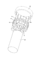
- FIG. 1 An exploded perspective view of the electric motor according to the first embodiment.
- Perspective view of the stator core according to the first embodiment Perspective view of the core back in the first embodiment
- FIG. 10 is a diagram showing a state in which a second winding portion is formed on the tooth portion shown in FIGS. 10 and 11, and is a view seen from the first insulator side.
- FIG. 12 is a view showing a state in which the insertion member is removed from the tooth portion shown in FIGS. 12 and 13, and is a perspective view seen from the first insulator side.
- 12 is a view showing a state in which the insertion member is removed from the tooth portion shown in FIGS. 12 and 13, and is a perspective view seen from the second insulator side.
- a perspective view of the stator according to the first embodiment as viewed from the first insulator side.
- a flowchart showing a manufacturing process of the electric motor according to the first embodiment.
- FIG. 1 is an exploded perspective view of the electric motor according to the first embodiment.
- the electric motor 50 is an inner rotor type electric motor in which the rotor 2 is arranged inside the tubular stator 1.
- the rotor 2 is provided with a shaft portion 23 extending along the central shaft 51 of the stator 1.
- the shaft portion 23 is rotatably supported by two bearings 3.
- the bearing 3 is supported by the outer shell 4 and the outer shell 5.
- the outer shell 4 and the outer shell 5 form a casing for accommodating the stator 1, the rotor 2, and the bearing 3 inside.
- the side having the outer shell 4 with respect to the stator 1 is referred to as one side
- the side having the outer shell 5 is referred to as the other side.
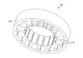
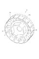
- FIG. 2 is a perspective view of the stator core according to the first embodiment.
- the stator core 52 includes a cylindrical core back 10 and a plurality of tooth portions 9 protruding from the inner peripheral surface of the core back 10 and arranged radially.
- the core back 10 and the tooth portion 9 are formed by laminating a plurality of steel plates along the central axis 51.
- the stator core 52 has two phases and four poles and has 16 slots.
- the terms inner peripheral side and outer peripheral side mean the inner peripheral side and outer peripheral side in the cylindrical shape of the core back 10.
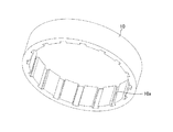
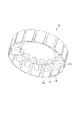
- FIG. 3 is a perspective view of the core back according to the first embodiment.
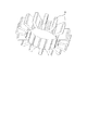
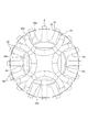
- FIG. 4 is a diagram showing a state in which the tooth portions in the first embodiment are arranged in a radial pattern. As shown in FIGS. 3 and 4, the core back 10 and the tooth portion 9 are separated and formed as separate bodies. A groove 10a for fitting the root portion of the tooth portion 9 is formed on the inner peripheral surface of the core back 10.
- a plurality of tooth portions 9 are arranged radially.
- FIG. 5 is a view showing a state in which a plurality of tooth portions are covered with an insulator in the first embodiment, and is a perspective view seen from the first insulator side.
- FIG. 6 is a view showing a state in which a plurality of tooth portions are covered with an insulator in the first embodiment, and is a perspective view seen from the second insulator side.
- the insulator 8 is made of an insulating material, for example, an insulating resin.
- the insulator 8 is divided into a first insulator 13 and a second insulator 14.
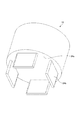
- FIG. 7 is a perspective view of the first insulator according to the first embodiment.
- the first insulator 13 covers the plurality of tooth portions 9 from one side along the central axis 51.
- the first insulator 13 has a first covering portion 13c that covers each of the tooth portions 9.
- the first insulator 13 has a lid portion 13a that closes a region surrounded by a plurality of tooth portions 9 when viewed along the central axis 51, that is, a region surrounded by the first covering portion 13c.
- the lid portion 13a is formed with a hole through which the shaft portion 23 penetrates.
- the lid portion 13a is formed with a rib-shaped first hook portion 13b projecting to one side. In the first embodiment, four first hook portions 13b are formed, but the number thereof varies depending on the number of poles of the stator core 52 and the like.
- FIG. 8 is a perspective view of the second insulator according to the first embodiment.
- the second insulator 15 covers the plurality of tooth portions 9 from the other side along the central axis 51.
- the second insulator 15 has a second covering portion 15c that covers each of the tooth portions 9.
- the second insulator 15 has a circular opening 15a in which the region surrounded by the plurality of tooth portions 9 when viewed along the central axis 51, that is, the region surrounded by the first covering portion 13c is not covered. There is.
- the rotor 2 is inserted into the opening 15a in a later step.
- the first insulator 13 has a wall 12 formed on the outer peripheral side of the first covering portion 13c.
- a slit 11 is formed in the wall 12.
- the second insulator 15 has a wall 19 formed on the outer peripheral side of the second covering portion 15c.
- a slit 18 is formed in the wall 19.
- the slits 11 and 18 are formed in a portion between the first covering portions 13c and a portion between the second covering portions 15c. A winding described later is inserted between the first covering portions 13c and between the second covering portions 15c through the slits 11 and 18.
- the wall 19 may be formed lower than the wall 12.
- FIG. 9 is a perspective view of the insertion member according to the first embodiment.
- the insertion member 41 is inserted into a region surrounded by a plurality of tooth portions 9 through the opening 15a of the second insulator 15.
- the insertion member 41 has a covering surface 24a that covers the region surrounded by the plurality of tooth portions 9 when viewed along the central axis 51 in a state of being inserted into the region surrounded by the plurality of tooth portions 9.
- a rib-shaped second hook portion 24b protruding to the other side is formed on the covering surface 24a.
- four second hook portions 24b are formed, but the number thereof varies depending on the number of poles of the stator core 52 and the like.
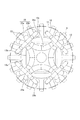
- FIG. 10 is a diagram showing a state in which the first winding portion is formed on the tooth portions shown in FIGS. 5 and 6, and is a view seen from the first insulator side.
- FIG. 11 is a view showing a state in which the first winding portion is formed on the tooth portion shown in FIGS. 5 and 6, and is a view seen from the second insulator side.
- the first winding portion 25a is formed by winding the winding around the tooth portion 9 via the insulator 8 while hooking the first hook portion 13b and the second hook portion 24b.
- the space between the tooth portions 9 is referred to as a slot 53.
- the first winding portion 25a does not pass through the adjacent slot 53, and the first winding portion 25a is between the slots 53 through which the first winding portion 25a passes.
- a slot 53 through which the winding portion 25a does not pass is provided.
- a portion protruding unilaterally from the first insulator 13 when viewed along the direction perpendicular to the central axis 51 is referred to as a winding end 25c.
- first winding portion 25a a portion protruding from the second insulator 15 to the other side when viewed along the direction perpendicular to the central axis 51 is referred to as a winding end 25d.
- first winding portion 25a since the first winding portion 25a is formed while hooking the winding on the first hook portion 13b and the second hook portion 24b, the winding ends 25c and 25d are the first.
- the winding portion 25a passes over the slot 53, which does not pass through.
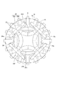
- FIG. 12 is a view showing a state in which a second winding portion is formed on the tooth portion shown in FIGS. 10 and 11, and is a view seen from the first insulator side.
- FIG. 13 is a view showing a state in which the second winding portion is formed on the tooth portion shown in FIGS. 10 and 11, and is a view seen from the second insulator side.
- the second winding portion 25b is wound around the tooth portion 9 via the insulator 8 by passing the winding through the slot 53 through which the first winding portion 25a does not pass. It is formed by winding.
- the portion of the second winding portion 25b that protrudes unilaterally from the first insulator 13 when viewed along the direction perpendicular to the central axis 51 is referred to as the winding end 25e.
- a portion protruding from the second insulator 15 to the other side when viewed along the direction perpendicular to the central axis 51 is referred to as a winding end 25f.
- winding ends 25c, 25d, 25e, 25f the winding ends 25c, 25e protruding to one side are the first winding ends, and the winding ends 25d, 25f protruding to the other side are the second windings.
- the line end is the first winding ends, and the winding ends 25d, 25f protruding to the other side are the second windings.
- the first winding portion 25a is formed while hooking the winding on the first hook portion 13b and the second hook portion 24b, the winding end 25c is formed. , 25d pass over the slot 53, which the first winding portion 25a does not pass through. Therefore, the winding ends 25c and 25d do not interfere with the formation of the second winding portion 25b, and the formation of the second winding portion 25b can be facilitated.
- the first winding portion 25a and the second winding portion 25b are not distinguished and are also referred to as a winding portion 25.
- the winding portion 25 has two phases. Four winding portions 25 are arranged per phase, for a total of eight winding portions 25. Since the winding portion 25 is directly wound around the insulator 8 from the outer peripheral portion of the tooth portion 9, it can be wound around the insulator 8 without a gap, and resource saving and cost reduction can be achieved by reducing the amount of winding. Further, since the resistance at the winding portion 25 is also reduced, the efficiency of the motor can be improved.
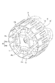
- FIG. 14 is a view showing a state in which the insertion member is removed from the tooth portions shown in FIGS. 12 and 13, and is a perspective view seen from the first insulator side.
- FIG. 15 is a view showing a state in which the insertion member is removed from the tooth portions shown in FIGS. 12 and 13, and is a perspective view seen from the second insulator side.
- the winding end 25d of the first winding portion 25a and the winding end 25f of the second winding portion 25b are deformed so as to be widened so as to be viewed along the central axis 51.
- the winding ends 25d and 25f are positioned on the outer peripheral side of the tips of the plurality of teeth.
- the insertion member 24 can be pulled out and removed without being disturbed by the winding ends 25d and 25f.
- the winding ends 25d and 25f can be deformed until they have a portion located on the outer peripheral side of the root of the tooth portion 9, the work of deforming the winding ends 25d and 25f can be facilitated. can.
- the wall 19 formed on the second insulator 15 is formed lower than the wall 12 formed on the first insulator 13, it has a portion located on the outer peripheral side of the root of the tooth portion 9.
- the winding ends 25d and 25f are easily deformed.
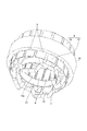
- FIG. 16 is a perspective view for explaining the connection between the tooth portion and the core bag in the first embodiment.
- the tubular jig 20 is inserted into the region surrounded by the tooth portion 9.
- the jig 20 supports the tooth portion 9 from the inner peripheral side by its outer peripheral surface 20a.
- the core back 10 is connected to the tooth portion 9 with the jig 20 inserted.
- the tooth portion 9 is supported from the inner peripheral side by the jig 20, it is possible to suppress the misalignment of the tooth portion 9 when connecting to the core back 10. Therefore, the position accuracy of the tooth portion 9 can be improved.
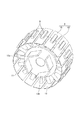
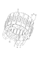
- FIG. 17 is a perspective view of the stator according to the first embodiment as viewed from the first insulator side.
- FIG. 18 is a perspective view of the stator according to the first embodiment as viewed from the second insulator side.
- the shaping of the winding portion 25 means that, for example, the winding ends 25d and 25f deformed to have a portion located on the outer peripheral side of the root of the tooth portion 9 are positioned on the inner peripheral side of the root of the tooth portion 9. Is to let.
- an insulating wall 22 for insulation may be additionally provided later.
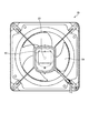
- FIG. 19 is a front view of a blower including the electric motor according to the first embodiment.
- the electric motor 50 may be used for the blower 55 in which the blade 54 is connected to the shaft portion 23 and the blade 54 is rotated to blow air.
- the electric motor 50 may be used as a ventilation fan for rotating the blades or impellers to flow air.
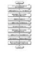
- FIG. 20 is a flowchart showing a manufacturing process of the electric motor according to the first embodiment.
- the core back 10 and the plurality of tooth portions 9 are separately formed (step S1).
- the plurality of tooth portions 9 are covered with the insulator 8 (step S2).
- the insertion member 24 is inserted into the region surrounded by the plurality of tooth portions 9 (step S3).
- the winding portion 25 is formed (step S4).
- the winding ends 25d and 25f are deformed (step S5).
- the insertion member 24 is removed (step S6).
- the jig 20 is inserted into the area surrounded by the plurality of tooth portions 9 (step S7).
- step S8 the tooth portion 9 and the core back 10 are connected (step S8).
- step S9 the jig 20 is pulled out and the winding portion 25 is shaped.
- step S10 the rotor 2 is provided inside the stator 1, and the bearing 3 and the outer shells 4 and 5 are provided (step S10), whereby the electric motor 50 is completed.
- the configuration shown in the above embodiments is an example, and can be combined with another known technique, can be combined with each other, and does not deviate from the gist. It is also possible to omit or change a part of the configuration.
- stator 1 stator, 2 rotor, 3 bearing, 4, 5 outer shell, 8 insulator, 9 tooth part, 10 core back, 10a groove, 11 slit, 12 wall, 13 first insulator, 13a lid part, 13b first Hook part, 13c 1st cover part, 15 2nd insulator, 15a opening, 15c 2nd cover part, 18 slit, 19 wall, 20 jig, 20a outer peripheral surface, 22 insulation wall, 23 shaft part, 24 insertion Member, 24a covering surface, 24b second hook part, 25 winding part, 25a first winding part, 25b second winding part, 25c, 25d, 25e, 25f winding end, 50 electric motor, 51 center Shaft, 52 stator core, 53 slots, 54 blades, 55 blower.
Landscapes
- Engineering & Computer Science (AREA)
- Manufacturing & Machinery (AREA)
- Power Engineering (AREA)
- Manufacture Of Motors, Generators (AREA)
- Insulation, Fastening Of Motor, Generator Windings (AREA)
Priority Applications (2)
| Application Number | Priority Date | Filing Date | Title |
|---|---|---|---|
| JP2022524817A JP7333871B2 (ja) | 2020-05-21 | 2020-05-21 | 固定子の製造方法、インナーロータ型電動機の製造方法、および固定子 |
| PCT/JP2020/020179 WO2021234925A1 (ja) | 2020-05-21 | 2020-05-21 | 固定子の製造方法、インナーロータ型電動機の製造方法、および固定子 |
Applications Claiming Priority (1)
| Application Number | Priority Date | Filing Date | Title |
|---|---|---|---|
| PCT/JP2020/020179 WO2021234925A1 (ja) | 2020-05-21 | 2020-05-21 | 固定子の製造方法、インナーロータ型電動機の製造方法、および固定子 |
Publications (1)
| Publication Number | Publication Date |
|---|---|
| WO2021234925A1 true WO2021234925A1 (ja) | 2021-11-25 |
Family
ID=78707877
Family Applications (1)
| Application Number | Title | Priority Date | Filing Date |
|---|---|---|---|
| PCT/JP2020/020179 Ceased WO2021234925A1 (ja) | 2020-05-21 | 2020-05-21 | 固定子の製造方法、インナーロータ型電動機の製造方法、および固定子 |
Country Status (2)
| Country | Link |
|---|---|
| JP (1) | JP7333871B2 (enExample) |
| WO (1) | WO2021234925A1 (enExample) |
Citations (3)
| Publication number | Priority date | Publication date | Assignee | Title |
|---|---|---|---|---|
| JPS53143901A (en) * | 1977-05-23 | 1978-12-14 | Hitachi Ltd | Coil end support |
| JPH05168204A (ja) * | 1991-12-13 | 1993-07-02 | Toshiba Corp | 誘導電動機の固定子の製造方法 |
| JP2006129590A (ja) * | 2004-10-28 | 2006-05-18 | Nippon Densan Corp | モータおよび電機子の製造方法 |
-
2020
- 2020-05-21 WO PCT/JP2020/020179 patent/WO2021234925A1/ja not_active Ceased
- 2020-05-21 JP JP2022524817A patent/JP7333871B2/ja active Active
Patent Citations (3)
| Publication number | Priority date | Publication date | Assignee | Title |
|---|---|---|---|---|
| JPS53143901A (en) * | 1977-05-23 | 1978-12-14 | Hitachi Ltd | Coil end support |
| JPH05168204A (ja) * | 1991-12-13 | 1993-07-02 | Toshiba Corp | 誘導電動機の固定子の製造方法 |
| JP2006129590A (ja) * | 2004-10-28 | 2006-05-18 | Nippon Densan Corp | モータおよび電機子の製造方法 |
Also Published As
| Publication number | Publication date |
|---|---|
| JP7333871B2 (ja) | 2023-08-25 |
| JPWO2021234925A1 (enExample) | 2021-11-25 |
Similar Documents
| Publication | Publication Date | Title |
|---|---|---|
| US7859164B2 (en) | Armature laminations | |
| US8847461B2 (en) | Split stator core having specific dimensions and motor including same | |
| US10439453B2 (en) | Stator | |
| US11909260B2 (en) | Coil formation in an electric machine with concentrated windings | |
| JP2005006366A (ja) | 電機子用インシュレータ | |
| US8823240B2 (en) | Stator and rotating electrical machine | |
| CN110247488B (zh) | 发电机的端部绕组的冷却 | |
| JP5239571B2 (ja) | 回転電機 | |
| JP7333871B2 (ja) | 固定子の製造方法、インナーロータ型電動機の製造方法、および固定子 | |
| CN205160244U (zh) | 一种马达及包括其的送风装置 | |
| JPH1014149A (ja) | 車両用発電機の電機子及びその製造方法 | |
| JP7395061B2 (ja) | 固定子、電動機、送風装置、固定子の製造方法および電動機の製造方法 | |
| WO2022209370A1 (ja) | 電動機用コイル、電動機用コイルの製造方法、及び電動機 | |
| JP4307219B2 (ja) | レゾルバ端子ピン構造 | |
| JP2019013114A (ja) | ブラシレスモータ、及び送風装置 | |
| JP2011176982A (ja) | スロットレスモータ | |
| CN111509891A (zh) | 电枢的骨架构造 | |
| JP2009033925A (ja) | シンクロナスリラクタンスモータ | |
| JP6776958B2 (ja) | ステータの製造方法 | |
| JP3575987B2 (ja) | 電動機の固定子 | |
| JP2021083183A (ja) | ステータ、およびモータ | |
| JP3999798B2 (ja) | 内転型電動機の固定子の製造方法 | |
| JP7109600B2 (ja) | アウターロータ型電動機及び天井扇風機 | |
| CN112152338A (zh) | 电机定子及具有其的电机、电机定子的制作方法 | |
| JP7246694B2 (ja) | モータ |
Legal Events
| Date | Code | Title | Description |
|---|---|---|---|
| 121 | Ep: the epo has been informed by wipo that ep was designated in this application |
Ref document number: 20936857 Country of ref document: EP Kind code of ref document: A1 |
|
| ENP | Entry into the national phase |
Ref document number: 2022524817 Country of ref document: JP Kind code of ref document: A |
|
| NENP | Non-entry into the national phase |
Ref country code: DE |
|
| 122 | Ep: pct application non-entry in european phase |
Ref document number: 20936857 Country of ref document: EP Kind code of ref document: A1 |