WO2021234925A1 - 固定子の製造方法、インナーロータ型電動機の製造方法、および固定子 - Google Patents
固定子の製造方法、インナーロータ型電動機の製造方法、および固定子 Download PDFInfo
- Publication number
- WO2021234925A1 WO2021234925A1 PCT/JP2020/020179 JP2020020179W WO2021234925A1 WO 2021234925 A1 WO2021234925 A1 WO 2021234925A1 JP 2020020179 W JP2020020179 W JP 2020020179W WO 2021234925 A1 WO2021234925 A1 WO 2021234925A1
- Authority
- WO
- WIPO (PCT)
- Prior art keywords
- winding
- insulator
- tooth
- core back
- stator
- Prior art date
- Legal status (The legal status is an assumption and is not a legal conclusion. Google has not performed a legal analysis and makes no representation as to the accuracy of the status listed.)
- Ceased
Links
Images




Classifications
-
- H—ELECTRICITY
- H02—GENERATION; CONVERSION OR DISTRIBUTION OF ELECTRIC POWER
- H02K—DYNAMO-ELECTRIC MACHINES
- H02K15/00—Processes or apparatus specially adapted for manufacturing, assembling, maintaining or repairing of dynamo-electric machines
- H02K15/10—Applying solid insulation to windings, stators or rotors, e.g. applying insulating tapes
-
- Y—GENERAL TAGGING OF NEW TECHNOLOGICAL DEVELOPMENTS; GENERAL TAGGING OF CROSS-SECTIONAL TECHNOLOGIES SPANNING OVER SEVERAL SECTIONS OF THE IPC; TECHNICAL SUBJECTS COVERED BY FORMER USPC CROSS-REFERENCE ART COLLECTIONS [XRACs] AND DIGESTS
- Y02—TECHNOLOGIES OR APPLICATIONS FOR MITIGATION OR ADAPTATION AGAINST CLIMATE CHANGE
- Y02T—CLIMATE CHANGE MITIGATION TECHNOLOGIES RELATED TO TRANSPORTATION
- Y02T10/00—Road transport of goods or passengers
- Y02T10/60—Other road transportation technologies with climate change mitigation effect
- Y02T10/64—Electric machine technologies in electromobility
Definitions
- This disclosure relates to a method of manufacturing a stator in which a winding is wound around a stator core, a method of manufacturing an inner rotor type motor, and a stator.
- the stator has a tubular core back portion and a plurality of tooth portions protruding from the inner peripheral surface of the core back and arranged in the circumferential direction.
- a winding is wound around the tooth portion to form a winding portion.
- the portion that protrudes in the central axis direction from the core back when viewed along the direction perpendicular to the central axis of the core back portion is called a winding end.
- the winding to be wound first is the tooth when viewed along the central axis. It overhangs to the inner circumference side from the tip of the part.
- the area on the inner peripheral side of the tip of the tooth is the area inside the stator.
- a rotor is provided inside the stator.
- the rotor when the rotor is formed in a size that does not interfere with the winding portion and the rotor can be inserted after the winding portion is formed, the gap between the tip of the tooth and the rotor, that is, the fixing is fixed. Since the gap between the child and the rotor becomes large, the efficiency of the electric motor decreases.
- the present disclosure has been made in view of the above, and an object thereof is to obtain a stator capable of downsizing the winding end and improving the efficiency of the motor.
- the present disclosure includes a tubular core back, a plurality of teeth protruding from the inner peripheral surface of the core back and arranged radially, and a plurality of teeth. Via a first insulator covering from one side along the central axis of the core back, a second insulator covering a plurality of teeth from the other side along the central axis, and a first insulator and a second insulator. It is a method of manufacturing a stator provided with a winding portion formed by winding a winding around a tooth portion.
- the first insulator has a first winding end that projects unilaterally from between the teeth in the winding portion in a region surrounded by the tips of a plurality of teeth when viewed along the central axis of the core back.
- a first hooking portion for hooking the tooth is formed.
- the core back and the plurality of teeth are formed separately, the plurality of teeth are arranged radially, the plurality of teeth are covered with the first insulator and the second insulator, and the central axis is on the second insulator side.
- a second hooking portion for hooking the second winding end protruding from between the tooth portions to the other side of the winding portion is provided in the region surrounded by the tip of the tooth portion when viewed along the above, and at least one tooth.
- a winding portion is formed by winding the winding while hooking the first hook portion and the second hook portion with respect to the portion, and the second winding end is viewed along the central axis and a plurality of tooth portions. It is deformed so that it is located on the outer peripheral side of the tip of the tooth. The second hook portion is removed, and a jig for supporting the tooth portion from the inner peripheral side is inserted into the region surrounded by the plurality of tooth portions, and the plurality of tooth portions and the core back are connected.
- the stator according to the present disclosure has the effect of being able to reduce the size of the winding end and improve the efficiency of the motor.
- FIG. 1 An exploded perspective view of the electric motor according to the first embodiment.
- Perspective view of the stator core according to the first embodiment Perspective view of the core back in the first embodiment
- FIG. 10 is a diagram showing a state in which a second winding portion is formed on the tooth portion shown in FIGS. 10 and 11, and is a view seen from the first insulator side.
- FIG. 12 is a view showing a state in which the insertion member is removed from the tooth portion shown in FIGS. 12 and 13, and is a perspective view seen from the first insulator side.
- 12 is a view showing a state in which the insertion member is removed from the tooth portion shown in FIGS. 12 and 13, and is a perspective view seen from the second insulator side.
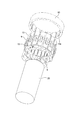
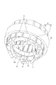
- a perspective view of the stator according to the first embodiment as viewed from the first insulator side.
- a flowchart showing a manufacturing process of the electric motor according to the first embodiment.
- FIG. 1 is an exploded perspective view of the electric motor according to the first embodiment.
- the electric motor 50 is an inner rotor type electric motor in which the rotor 2 is arranged inside the tubular stator 1.
- the rotor 2 is provided with a shaft portion 23 extending along the central shaft 51 of the stator 1.
- the shaft portion 23 is rotatably supported by two bearings 3.
- the bearing 3 is supported by the outer shell 4 and the outer shell 5.
- the outer shell 4 and the outer shell 5 form a casing for accommodating the stator 1, the rotor 2, and the bearing 3 inside.
- the side having the outer shell 4 with respect to the stator 1 is referred to as one side
- the side having the outer shell 5 is referred to as the other side.
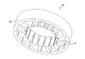
- FIG. 2 is a perspective view of the stator core according to the first embodiment.
- the stator core 52 includes a cylindrical core back 10 and a plurality of tooth portions 9 protruding from the inner peripheral surface of the core back 10 and arranged radially.
- the core back 10 and the tooth portion 9 are formed by laminating a plurality of steel plates along the central axis 51.
- the stator core 52 has two phases and four poles and has 16 slots.
- the terms inner peripheral side and outer peripheral side mean the inner peripheral side and outer peripheral side in the cylindrical shape of the core back 10.
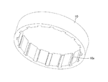
- FIG. 3 is a perspective view of the core back according to the first embodiment.
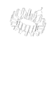
- FIG. 4 is a diagram showing a state in which the tooth portions in the first embodiment are arranged in a radial pattern. As shown in FIGS. 3 and 4, the core back 10 and the tooth portion 9 are separated and formed as separate bodies. A groove 10a for fitting the root portion of the tooth portion 9 is formed on the inner peripheral surface of the core back 10.
- a plurality of tooth portions 9 are arranged radially.
- FIG. 5 is a view showing a state in which a plurality of tooth portions are covered with an insulator in the first embodiment, and is a perspective view seen from the first insulator side.
- FIG. 6 is a view showing a state in which a plurality of tooth portions are covered with an insulator in the first embodiment, and is a perspective view seen from the second insulator side.
- the insulator 8 is made of an insulating material, for example, an insulating resin.
- the insulator 8 is divided into a first insulator 13 and a second insulator 14.
- FIG. 7 is a perspective view of the first insulator according to the first embodiment.
- the first insulator 13 covers the plurality of tooth portions 9 from one side along the central axis 51.
- the first insulator 13 has a first covering portion 13c that covers each of the tooth portions 9.
- the first insulator 13 has a lid portion 13a that closes a region surrounded by a plurality of tooth portions 9 when viewed along the central axis 51, that is, a region surrounded by the first covering portion 13c.
- the lid portion 13a is formed with a hole through which the shaft portion 23 penetrates.
- the lid portion 13a is formed with a rib-shaped first hook portion 13b projecting to one side. In the first embodiment, four first hook portions 13b are formed, but the number thereof varies depending on the number of poles of the stator core 52 and the like.
- FIG. 8 is a perspective view of the second insulator according to the first embodiment.
- the second insulator 15 covers the plurality of tooth portions 9 from the other side along the central axis 51.
- the second insulator 15 has a second covering portion 15c that covers each of the tooth portions 9.
- the second insulator 15 has a circular opening 15a in which the region surrounded by the plurality of tooth portions 9 when viewed along the central axis 51, that is, the region surrounded by the first covering portion 13c is not covered. There is.
- the rotor 2 is inserted into the opening 15a in a later step.
- the first insulator 13 has a wall 12 formed on the outer peripheral side of the first covering portion 13c.
- a slit 11 is formed in the wall 12.
- the second insulator 15 has a wall 19 formed on the outer peripheral side of the second covering portion 15c.
- a slit 18 is formed in the wall 19.
- the slits 11 and 18 are formed in a portion between the first covering portions 13c and a portion between the second covering portions 15c. A winding described later is inserted between the first covering portions 13c and between the second covering portions 15c through the slits 11 and 18.
- the wall 19 may be formed lower than the wall 12.
- FIG. 9 is a perspective view of the insertion member according to the first embodiment.
- the insertion member 41 is inserted into a region surrounded by a plurality of tooth portions 9 through the opening 15a of the second insulator 15.
- the insertion member 41 has a covering surface 24a that covers the region surrounded by the plurality of tooth portions 9 when viewed along the central axis 51 in a state of being inserted into the region surrounded by the plurality of tooth portions 9.
- a rib-shaped second hook portion 24b protruding to the other side is formed on the covering surface 24a.
- four second hook portions 24b are formed, but the number thereof varies depending on the number of poles of the stator core 52 and the like.
- FIG. 10 is a diagram showing a state in which the first winding portion is formed on the tooth portions shown in FIGS. 5 and 6, and is a view seen from the first insulator side.
- FIG. 11 is a view showing a state in which the first winding portion is formed on the tooth portion shown in FIGS. 5 and 6, and is a view seen from the second insulator side.
- the first winding portion 25a is formed by winding the winding around the tooth portion 9 via the insulator 8 while hooking the first hook portion 13b and the second hook portion 24b.
- the space between the tooth portions 9 is referred to as a slot 53.
- the first winding portion 25a does not pass through the adjacent slot 53, and the first winding portion 25a is between the slots 53 through which the first winding portion 25a passes.
- a slot 53 through which the winding portion 25a does not pass is provided.
- a portion protruding unilaterally from the first insulator 13 when viewed along the direction perpendicular to the central axis 51 is referred to as a winding end 25c.
- first winding portion 25a a portion protruding from the second insulator 15 to the other side when viewed along the direction perpendicular to the central axis 51 is referred to as a winding end 25d.
- first winding portion 25a since the first winding portion 25a is formed while hooking the winding on the first hook portion 13b and the second hook portion 24b, the winding ends 25c and 25d are the first.
- the winding portion 25a passes over the slot 53, which does not pass through.
- FIG. 12 is a view showing a state in which a second winding portion is formed on the tooth portion shown in FIGS. 10 and 11, and is a view seen from the first insulator side.
- FIG. 13 is a view showing a state in which the second winding portion is formed on the tooth portion shown in FIGS. 10 and 11, and is a view seen from the second insulator side.
- the second winding portion 25b is wound around the tooth portion 9 via the insulator 8 by passing the winding through the slot 53 through which the first winding portion 25a does not pass. It is formed by winding.
- the portion of the second winding portion 25b that protrudes unilaterally from the first insulator 13 when viewed along the direction perpendicular to the central axis 51 is referred to as the winding end 25e.
- a portion protruding from the second insulator 15 to the other side when viewed along the direction perpendicular to the central axis 51 is referred to as a winding end 25f.
- winding ends 25c, 25d, 25e, 25f the winding ends 25c, 25e protruding to one side are the first winding ends, and the winding ends 25d, 25f protruding to the other side are the second windings.
- the line end is the first winding ends, and the winding ends 25d, 25f protruding to the other side are the second windings.
- the first winding portion 25a is formed while hooking the winding on the first hook portion 13b and the second hook portion 24b, the winding end 25c is formed. , 25d pass over the slot 53, which the first winding portion 25a does not pass through. Therefore, the winding ends 25c and 25d do not interfere with the formation of the second winding portion 25b, and the formation of the second winding portion 25b can be facilitated.
- the first winding portion 25a and the second winding portion 25b are not distinguished and are also referred to as a winding portion 25.
- the winding portion 25 has two phases. Four winding portions 25 are arranged per phase, for a total of eight winding portions 25. Since the winding portion 25 is directly wound around the insulator 8 from the outer peripheral portion of the tooth portion 9, it can be wound around the insulator 8 without a gap, and resource saving and cost reduction can be achieved by reducing the amount of winding. Further, since the resistance at the winding portion 25 is also reduced, the efficiency of the motor can be improved.
- FIG. 14 is a view showing a state in which the insertion member is removed from the tooth portions shown in FIGS. 12 and 13, and is a perspective view seen from the first insulator side.
- FIG. 15 is a view showing a state in which the insertion member is removed from the tooth portions shown in FIGS. 12 and 13, and is a perspective view seen from the second insulator side.
- the winding end 25d of the first winding portion 25a and the winding end 25f of the second winding portion 25b are deformed so as to be widened so as to be viewed along the central axis 51.
- the winding ends 25d and 25f are positioned on the outer peripheral side of the tips of the plurality of teeth.
- the insertion member 24 can be pulled out and removed without being disturbed by the winding ends 25d and 25f.
- the winding ends 25d and 25f can be deformed until they have a portion located on the outer peripheral side of the root of the tooth portion 9, the work of deforming the winding ends 25d and 25f can be facilitated. can.
- the wall 19 formed on the second insulator 15 is formed lower than the wall 12 formed on the first insulator 13, it has a portion located on the outer peripheral side of the root of the tooth portion 9.
- the winding ends 25d and 25f are easily deformed.
- FIG. 16 is a perspective view for explaining the connection between the tooth portion and the core bag in the first embodiment.
- the tubular jig 20 is inserted into the region surrounded by the tooth portion 9.
- the jig 20 supports the tooth portion 9 from the inner peripheral side by its outer peripheral surface 20a.
- the core back 10 is connected to the tooth portion 9 with the jig 20 inserted.
- the tooth portion 9 is supported from the inner peripheral side by the jig 20, it is possible to suppress the misalignment of the tooth portion 9 when connecting to the core back 10. Therefore, the position accuracy of the tooth portion 9 can be improved.
- FIG. 17 is a perspective view of the stator according to the first embodiment as viewed from the first insulator side.
- FIG. 18 is a perspective view of the stator according to the first embodiment as viewed from the second insulator side.
- the shaping of the winding portion 25 means that, for example, the winding ends 25d and 25f deformed to have a portion located on the outer peripheral side of the root of the tooth portion 9 are positioned on the inner peripheral side of the root of the tooth portion 9. Is to let.
- an insulating wall 22 for insulation may be additionally provided later.
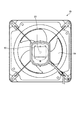
- FIG. 19 is a front view of a blower including the electric motor according to the first embodiment.
- the electric motor 50 may be used for the blower 55 in which the blade 54 is connected to the shaft portion 23 and the blade 54 is rotated to blow air.
- the electric motor 50 may be used as a ventilation fan for rotating the blades or impellers to flow air.
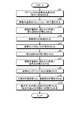
- FIG. 20 is a flowchart showing a manufacturing process of the electric motor according to the first embodiment.
- the core back 10 and the plurality of tooth portions 9 are separately formed (step S1).
- the plurality of tooth portions 9 are covered with the insulator 8 (step S2).
- the insertion member 24 is inserted into the region surrounded by the plurality of tooth portions 9 (step S3).
- the winding portion 25 is formed (step S4).
- the winding ends 25d and 25f are deformed (step S5).
- the insertion member 24 is removed (step S6).
- the jig 20 is inserted into the area surrounded by the plurality of tooth portions 9 (step S7).
- step S8 the tooth portion 9 and the core back 10 are connected (step S8).
- step S9 the jig 20 is pulled out and the winding portion 25 is shaped.
- step S10 the rotor 2 is provided inside the stator 1, and the bearing 3 and the outer shells 4 and 5 are provided (step S10), whereby the electric motor 50 is completed.
- the configuration shown in the above embodiments is an example, and can be combined with another known technique, can be combined with each other, and does not deviate from the gist. It is also possible to omit or change a part of the configuration.
- stator 1 stator, 2 rotor, 3 bearing, 4, 5 outer shell, 8 insulator, 9 tooth part, 10 core back, 10a groove, 11 slit, 12 wall, 13 first insulator, 13a lid part, 13b first Hook part, 13c 1st cover part, 15 2nd insulator, 15a opening, 15c 2nd cover part, 18 slit, 19 wall, 20 jig, 20a outer peripheral surface, 22 insulation wall, 23 shaft part, 24 insertion Member, 24a covering surface, 24b second hook part, 25 winding part, 25a first winding part, 25b second winding part, 25c, 25d, 25e, 25f winding end, 50 electric motor, 51 center Shaft, 52 stator core, 53 slots, 54 blades, 55 blower.
Landscapes
- Engineering & Computer Science (AREA)
- Manufacturing & Machinery (AREA)
- Power Engineering (AREA)
- Manufacture Of Motors, Generators (AREA)
- Insulation, Fastening Of Motor, Generator Windings (AREA)
Abstract
筒状のコアバックと、複数の歯部と、複数の歯部を一方側から覆う第1のインシュレータと、他方側から覆う第2のインシュレータと、歯部に巻線を巻き付けて形成された巻線部(25)と、を備える固定子(1)の製造方法である。第1のインシュレータには、一方側に突出する第1の巻線エンドを引っ掛ける第1の引っ掛け部が形成されている。コアバックと、複数の歯部とを別体で形成し、複数の歯部を第1のインシュレータおよび第2のインシュレータで覆い、第2のインシュレータ側に、他方側に突出する第2の巻線エンドを引っ掛ける第2の引っ掛け部を設け、第1の引っ掛け部および第2の引っ掛け部に巻線を引っ掛けながら巻線部を形成し、第2の巻線エンドを複数の歯部の先端よりも外周側に位置するように変形させる。複数の歯部に囲まれた領域に治具を挿入して、複数の歯部とコアバックとを結合させる。
Description
本開示は、固定子鉄心に巻線が巻き付けられた固定子の製造方法、インナーロータ型電動機の製造方法、および固定子に関する。
電動機には、筒状の固定子の内側に回転子が配置されたインナーロータ型電動機がある。固定子は、筒状のコアバック部と、コアバックの内周面から突出して周方向に並べられた複数の歯部を有する。歯部には巻線が巻き付けられて巻線部が形成される。巻線部のうち、コアバック部の中心軸に垂直な方向に沿って見てコアバックから中心軸方向に突出する部分は、巻線エンドと呼ばれる。巻線部に占める巻線エンドの量が増えると、材料費の増加によるコスト増加に加えて、巻線が長くなることによって抵抗が増加して、電動機の効率が低下してしまう。
予め円環状に形成された巻線部を歯部に差し込む方法では、余裕を持たせた大きさで巻線部を形成する必要があるため、巻線エンドが大きくなってしまう。そこで、特許文献1では、コアバック部と歯部とを分割形成し、周方向に並べた複数の歯部に直接巻線を巻き付けてから、コアバック部と歯部とを組み付けることで、巻線エンドの小型化が図られている。
しかしながら、歯部に巻線を巻き付けて巻線エンドの小型化を図る場合には、後から巻き付ける巻線の経路を確保するために、最初に巻き付ける巻線が、中心軸に沿って見て歯部の先端よりも内周側に張り出してしまう。
ティースの先端の内周側となる領域は、固定子の内側となる領域である。上述したように、固定子の内側には回転子が設けられる。
巻線を巻き付けて巻線部を形成してから、固定子の内側に回転子を差し込もうとすると、張り出した巻線に干渉してしまい、回転子を差し込むことができない場合がある。この場合、巻線を巻き付ける前にティースの先端の内周側となる領域に回転子を差し込んでおく必要がある。しかしながら、ティースの先端と回転子と間には隙間が設けられているため、ティースの内周側からの支持が不十分となり、コアバック部との連結の際に歯部の位置精度が低下してしまう場合がある。
一方、巻線部に干渉しない大きさで回転子を形成して、巻線部を形成してから回転子を差し込めるようにした場合には、ティースの先端と回転子との隙間、すなわち固定子と回転子との隙間が大きくなるため、電動機の効率が低下してしまう。
本開示は、上記に鑑みてなされたものであって、巻線エンドの小型化と電動機の効率向上を図ることができる固定子を得ることを目的とする。
上述した課題を解決し、目的を達成するために、本開示は、筒状のコアバックと、コアバックの内周面から突出して放射状に並べられた複数の歯部と、複数の歯部をコアバックの中心軸に沿った一方側から覆う第1のインシュレータと、複数の歯部を中心軸に沿った他方側から覆う第2のインシュレータと、第1のインシュレータおよび第2のインシュレータを介して歯部に巻線を巻き付けて形成された巻線部と、を備える固定子の製造方法である。第1のインシュレータには、コアバックの中心軸に沿って見て複数の歯部の先端に囲まれる領域に、巻線部のうち歯部の間から一方側に突出する第1の巻線エンドを引っ掛ける第1の引っ掛け部が形成されている。コアバックと、複数の歯部とを別体で形成し、複数の歯部を放射状に並べ、複数の歯部を第1のインシュレータおよび第2のインシュレータで覆い、第2のインシュレータ側で中心軸に沿って見て歯部の先端に囲まれる領域に、巻線部のうち歯部の間から他方側に突出する第2の巻線エンドを引っ掛ける第2の引っ掛け部を設け、少なくとも一つの歯部に対して、第1の引っ掛け部および第2の引っ掛け部に引っ掛けながら巻線を巻き付けて巻線部を形成し、第2の巻線エンドを、中心軸に沿って見て複数の歯部の先端よりも外周側に位置するように変形させる。第2の引っ掛け部を取り除き、複数の歯部に囲まれた領域に歯部を内周側から支持する治具を挿入し、複数の歯部とコアバックとを結合させる。
本開示にかかる固定子は、巻線エンドの小型化と電動機の効率向上を図ることができるという効果を奏する。
以下に、実施の形態にかかる固定子の製造方法、インナーロータ型電動機の製造方法、および固定子を図面に基づいて詳細に説明する。
実施の形態1.
図1は、実施の形態1にかかる電動機の分解斜視図である。電動機50は、筒状形状の固定子1の内側に回転子2が配置されたインナーロータ型電動機である。回転子2には、固定子1の中心軸51に沿って伸びる軸部23が設けられている。軸部23は、2つの軸受け3によって回転可能に支持されている。軸受け3は、外郭4と外郭5とによって支持されている。外郭4と外郭5とで、固定子1、回転子2、軸受け3を内部に収容するケーシングとなる。以下の説明において、図1に示す状態で固定子1に対して外郭4がある側を一方側と称し、外郭5がある側を他方側と称する。
図1は、実施の形態1にかかる電動機の分解斜視図である。電動機50は、筒状形状の固定子1の内側に回転子2が配置されたインナーロータ型電動機である。回転子2には、固定子1の中心軸51に沿って伸びる軸部23が設けられている。軸部23は、2つの軸受け3によって回転可能に支持されている。軸受け3は、外郭4と外郭5とによって支持されている。外郭4と外郭5とで、固定子1、回転子2、軸受け3を内部に収容するケーシングとなる。以下の説明において、図1に示す状態で固定子1に対して外郭4がある側を一方側と称し、外郭5がある側を他方側と称する。
図2は、実施の形態1における固定子鉄心の斜視図である。固定子鉄心52は、円筒形状のコアバック10と、コアバック10の内周面から突出して放射状に並べられた複数の歯部9とを備える。コアバック10および歯部9は、複数枚の鋼板を中心軸51に沿って積層して形成されている。固定子鉄心52は、2相4極であり16スロットである。なお、本明細書において内周側および外周側といった場合には、コアバック10の円筒形状における内周側および外周側を意味する。
図3は、実施の形態1におけるコアバックの斜視図である。図4は、実施の形態1における歯部が放射状に並べられた状態を示す図である。図3および図4に示すように、コアバック10と歯部9とは分割して別体で形成されている。コアバック10の内周面には、歯部9の根本部を嵌める溝10aが形成されている。固定子1を製造する際には、まず図4に示すように、複数の歯部9が放射状に並べられる。
図5は、実施の形態1において複数の歯部がインシュレータに覆われた状態を示す図であって、第1のインシュレータ側から見た斜視図である。図6は、実施の形態1において複数の歯部がインシュレータに覆われた状態を示す図であって、第2のインシュレータ側から見た斜視図である。
図5および図6に示すように、放射状に並べられた複数の歯部9がインシュレータ8によって覆われる。インシュレータ8は、絶縁性の材料、例えば絶縁性の樹脂で形成されている。インシュレータ8は、第1のインシュレータ13と第2のインシュレータ14とに分割される。
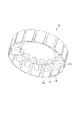
図7は、実施の形態1における第1のインシュレータの斜視図である。第1のインシュレータ13は、複数の歯部9を中心軸51に沿った一方側から覆う。第1のインシュレータ13は、歯部9のそれぞれを覆う第1の覆い部13cを有する。第1のインシュレータ13は、中心軸51に沿って見て複数の歯部9に囲まれる領域、すなわち、第1の覆い部13cに囲まれる領域を塞ぐ蓋部13aを有する。蓋部13aには、軸部23を貫通させる穴が形成されている。蓋部13aには、一方側に突出するリブ状の第1の引っ掛け部13bが形成されている。本実施の形態1では、4つの第1の引っ掛け部13bが形成されているが、その数は固定子鉄心52の極数等により異なる。
図8は、実施の形態1における第2のインシュレータの斜視図である。第2のインシュレータ15は、複数の歯部9を中心軸51に沿った他方側から覆う。第2のインシュレータ15は、歯部9のそれぞれを覆う第2の覆い部15cを有する。第2のインシュレータ15は、中心軸51に沿って見て複数の歯部9に囲まれる領域、すなわち、第1の覆い部13cに囲まれる領域が覆われておらず円形の開口15aとなっている。開口15aには、後の工程で回転子2が差し込まれる。
第1のインシュレータ13は、第1の覆い部13cの外周側に形成された壁12を有する。壁12にはスリット11が形成されている。第2のインシュレータ15は、第2の覆い部15cの外周側に形成された壁19を有する。壁19にはスリット18が形成されている。スリット11,18は、第1の覆い部13c同士の間となる部分および第2の覆い部15c同士の間となる部分に形成されている。後述する巻線がスリット11,18の間を通して第1の覆い部13c同士の間および第2の覆い部15c同士の間に差し込まれる。なお、壁19は壁12よりも低く形成されていてもよい。
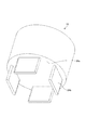
図9は、実施の形態1における挿入部材の斜視図である。挿入部材41は、第2のインシュレータ15の開口15aから、複数の歯部9に囲まれる領域に挿入される。挿入部材41は、複数の歯部9に囲まれる領域に挿入された状態で、中心軸51に沿って見て複数の歯部9に囲まれる領域を覆う覆い面24aを有する。覆い面24aには、他方側に突出するリブ状の第2の引っ掛け部24bが形成されている。本実施の形態1では、4つの第2の引っ掛け部24bが形成されているが、その数は固定子鉄心52の極数等により異なる。
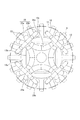
図10は、図5および図6に示した歯部に第1の巻線部が形成された状態を示す図であって、第1のインシュレータ側から見た図である。図11は、図5および図6に示した歯部に第1の巻線部が形成された状態を示す図であって、第2のインシュレータ側から見た図である。
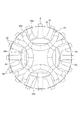
第1の巻線部25aは、第1の引っ掛け部13bおよび第2の引っ掛け部24bに引っ掛けながら、インシュレータ8を介して歯部9に巻線を巻き付けることで形成される。ここで、歯部9同士の間の空間をスロット53とする。図10および図11に示すように、第1の巻線部25aは、隣接するスロット53を通過しておらず、第1の巻線部25aが通過するスロット53の間には、第1の巻線部25aが通過しないスロット53が設けられている。ここで、第1の巻線部25aのうち、中心軸51に垂直な方向に沿って見て、第1のインシュレータ13から一方側に突出する部分を巻線エンド25cとする。また、第1の巻線部25aのうち、中心軸51に垂直な方向に沿って見て、第2のインシュレータ15から他方側に突出する部分を巻線エンド25dとする。本実施の形態1では、第1の引っ掛け部13bおよび第2の引っ掛け部24bに巻線を引っ掛けながら第1の巻線部25aが形成されるため、巻線エンド25c,25dが、第1の巻線部25aが通過しないスロット53の上を避けて通過している。
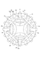
図12は、図10および図11に示した歯部に第2の巻線部が形成された状態を示す図であって、第1のインシュレータ側から見た図である。図13は、図10および図11に示した歯部に第2の巻線部が形成された状態を示す図であって、第2のインシュレータ側から見た図である。
図12および図13に示すように、第2の巻線部25bは、第1の巻線部25aが通過しないスロット53に巻線を通過させて、インシュレータ8を介して歯部9に巻線を巻き付けることで形成されている。ここで、第2の巻線部25bのうち、中心軸51に垂直な方向に沿って見て、第1のインシュレータ13から一方側に突出する部分を巻線エンド25eとする。また、第2の巻線部25bのうち、中心軸51に垂直な方向に沿って見て、第2のインシュレータ15から他方側に突出する部分を巻線エンド25fとする。巻線エンド25c,25d,25e,25fのうち、一方側に突出する巻線エンド25c,25eは第1の巻線エンドであり、他方側に突出する巻線エンド25d,25fは第2の巻線エンドである。
第1の巻線部25aが通過しないスロット53には、第1の巻線部25aよりも後に形成される第2の巻線部25bが通過する。第1の巻線部25aが通過しないスロット53の上を第1の巻線部25aの巻線エンド25c,25dが通過してしまうと、第2の巻線部25bを形成しにくくなってしまう。一方、本実施の形態1では、上述したように、第1の引っ掛け部13bおよび第2の引っ掛け部24bに巻線を引っ掛けながら第1の巻線部25aが形成されるため、巻線エンド25c,25dが、第1の巻線部25aが通過しないスロット53の上を避けて通過している。したがって、巻線エンド25c,25dが第2の巻線部25bの形成の邪魔にならず、第2の巻線部25bの形成の容易化が図られる。
なお、以下の説明において、第1の巻線部25aと第2の巻線部25bとを区別せずに巻線部25とも称する。巻線部25は2相である。1相あたり4個、合計で8個の巻線部25が配置される。巻線部25は歯部9の外周部から直接インシュレータ8に巻き付けるため、隙間なくインシュレータ8に巻き付けることができ、巻線の量を減らす省資源化および低コスト化を図ることができる。また、巻線部25での抵抗も減るため、電動機の高効率化を図ることができる。
巻線部25を形成した後に、挿入部材24が取り除かれる。図14は、図12および図13に示した歯部から挿入部材を取り除いた状態を示す図であって、第1のインシュレータ側から見た斜視図である。図15は、図12および図13に示した歯部から挿入部材を取り除いた状態を示す図であって、第2のインシュレータ側から見た斜視図である。
まず、図15に示すように、第1の巻線部25aの巻線エンド25dおよび第2の巻線部25bの巻線エンド25fを広げるように変形させることで、中心軸51に沿って見て複数の歯部の先端よりも外周側に巻線エンド25d,25fを位置させる。これにより、巻線エンド25d,25fに邪魔されずに挿入部材24を抜き取って取り除くことが可能となる。このとき、巻線エンド25d,25fを、歯部9の根本よりも外周側に位置する部分を有するまで変形させることができれば、巻線エンド25d,25fを変形させる作業の容易化を図ることができる。例えば、第2のインシュレータ15に形成された壁19が第1のインシュレータ13に形成された壁12よりも低く形成されていれば、歯部9の根本よりも外周側に位置する部分を有するまで巻線エンド25d,25fを変形させやすくなる。
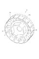
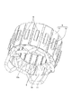
次に、歯部9とコアバック10とを連結させて、固定子1が形成される。図16は、実施の形態1のおける歯部とコアバックとの連結について説明するための斜視図である。歯部9とコアバック10とを連結させる場合には、まず、歯部9に囲まれた領域に筒状の治具20が挿入される。治具20は、その外周面20aで歯部9を内周側から支持する。次に、治具20が挿入された状態でコアバック10が歯部9に連結される。
治具20によって歯部9が内周側から支持されているので、コアバック10との連結の際に歯部9の位置ずれを抑えることができる。したがって、歯部9の位置精度の向上を図ることができる。
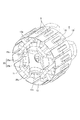
歯部9とコアバック10とを連結してから治具20を抜き取り、巻線部25を整形することで固定子1が完成する。図17は、実施の形態1にかかる固定子を第1のインシュレータ側から見た斜視図である。図18は、実施の形態1にかかる固定子を第2のインシュレータ側から見た斜視図である。
巻線部25の整形とは、例えば、歯部9の根本よりも外周側に位置する部分を有するまで変形させた巻線エンド25d,25fを、歯部9の根本よりも内周側に位置させることである。
また、図18に示すように回転子2と巻線エンド25d,25fとの絶縁を確保するために、絶縁用の絶縁壁22を後から追加して設けてもよい。
図19は、実施の形態1にかかる電動機を備える送風機の正面図である。図19に示すように、軸部23に羽根54を連結し、羽根54を回転させて送風する送風機55に電動機50を用いてもよい。なお、羽根または羽根車を回転させて空気を流動させる換気扇に電動機50を用いてもよい。
次に、電動機50の製造工程について、フローチャートを用いて簡単に説明する。図20は、実施の形態1にかかる電動機の製造工程を示すフローチャートである。まず、コアバック10と複数の歯部9とが別々に形成される(ステップS1)。次に、複数の歯部9がインシュレータ8で覆われる(ステップS2)。次に、複数の歯部9に囲まれた領域に挿入部材24が挿入される(ステップS3)。次に、巻線部25が形成される(ステップS4)。次に、巻線エンド25d,25fが変形される(ステップS5)。次に、挿入部材24が取り除かれる(ステップS6)。次に、複数の歯部9に囲まれた領域に治具20が挿入される(ステップS7)。次に、歯部9とコアバック10とが連結される(ステップS8)。次に、治具20が抜き取られ、巻線部25が整形される(ステップS9)。次に、固定子1の内側に回転子2が設けられ、軸受け3および外郭4,5が設けられることで(ステップS10)、電動機50が完成する。
以上の実施の形態に示した構成は、一例を示すものであり、別の公知の技術と組み合わせることも可能であるし、実施の形態同士を組み合わせることも可能であるし、要旨を逸脱しない範囲で、構成の一部を省略、変更することも可能である。
1 固定子、2 回転子、3 軸受け、4,5 外郭、8 インシュレータ、9 歯部、10 コアバック、10a 溝、11 スリット、12 壁、13 第1のインシュレータ、13a 蓋部、13b 第1の引っ掛け部、13c 第1の覆い部、15 第2のインシュレータ、15a 開口、15c 第2の覆い部、18 スリット、19 壁、20 治具、20a 外周面、22 絶縁壁、23 軸部、24 挿入部材、24a 覆い面、24b 第2の引っ掛け部、25 巻線部、25a 第1の巻線部、25b 第2の巻線部、25c,25d,25e,25f 巻線エンド、50 電動機、51 中心軸、52 固定子鉄心、53 スロット、54 羽根、55 送風機。
Claims (4)
- 筒状のコアバックと、前記コアバックの内周面から突出して放射状に並べられた複数の歯部と、複数の前記歯部を前記コアバックの中心軸に沿った一方側から覆う第1のインシュレータと、複数の前記歯部を前記中心軸に沿った他方側から覆う第2のインシュレータと、前記第1のインシュレータおよび前記第2のインシュレータを介して前記歯部に巻線を巻き付けて形成された巻線部と、を備える固定子の製造方法であって、
前記第1のインシュレータには、前記コアバックの中心軸に沿って見て複数の前記歯部の先端に囲まれる領域に、前記巻線部のうち前記歯部の間から前記一方側に突出する第1の巻線エンドを引っ掛ける第1の引っ掛け部が形成されており、
前記コアバックと、複数の前記歯部とを別体で形成し、
複数の前記歯部を放射状に並べ、
複数の前記歯部を前記第1のインシュレータおよび前記第2のインシュレータで覆い、
前記第2のインシュレータ側で前記中心軸に沿って見て前記歯部の先端に囲まれる領域に、前記巻線部のうち前記歯部の間から前記他方側に突出する第2の巻線エンドを引っ掛ける第2の引っ掛け部を設け、
少なくとも一つの前記歯部に対して、前記第1の引っ掛け部および前記第2の引っ掛け部に引っ掛けながら前記巻線を巻き付けて前記巻線部を形成し、
前記第2の巻線エンドを、前記中心軸に沿って見て複数の前記歯部の先端よりも外周側に位置するように変形させ、
前記第2の引っ掛け部を取り除き、
複数の前記歯部に囲まれた領域に前記歯部を内周側から支持する治具を挿入し、
複数の前記歯部と前記コアバックとを結合させることを特徴とする固定子の製造方法。 - 前記第2の巻線エンドの内周側に絶縁性の壁を設けることを特徴とする請求項1に記載の固定子の製造方法。
- 請求項1または2に記載された固定子の製造方法で製造された固定子に対して、複数の前記歯部の内周側に回転子を挿入することを特徴とするインナーロータ型電動機の製造方法。
- 筒状形状のコアバックと、
前記コアバックの内周面から突出して周方向に並べられた複数の歯部と、
複数の前記歯部を覆うインシュレータと、
前記インシュレータを介して前記歯部に巻線を巻き付けて形成された巻線部と、を備え、
前記コアバックと複数の前記歯部とは分割して形成されており、
前記インシュレータは、第1のインシュレータと第2のインシュレータとに前記コアバックの中心軸方向に分割可能とされており、
前記第1のインシュレータには、前記コアバックの中心軸に沿って見て複数の前記歯部の先端に囲まれる領域に、前記巻線部のうち前記歯部の間から前記中心軸に沿った方向に突出する巻線エンドを引っ掛ける引っ掛け部が形成されており、
前記第2のインシュレータ側では、前記中心軸に沿って見て前記巻線エンドが複数の前記歯部の先端よりも外周側に設けられていることを特徴とする固定子。
Priority Applications (2)
| Application Number | Priority Date | Filing Date | Title |
|---|---|---|---|
| PCT/JP2020/020179 WO2021234925A1 (ja) | 2020-05-21 | 2020-05-21 | 固定子の製造方法、インナーロータ型電動機の製造方法、および固定子 |
| JP2022524817A JP7333871B2 (ja) | 2020-05-21 | 2020-05-21 | 固定子の製造方法、インナーロータ型電動機の製造方法、および固定子 |
Applications Claiming Priority (1)
| Application Number | Priority Date | Filing Date | Title |
|---|---|---|---|
| PCT/JP2020/020179 WO2021234925A1 (ja) | 2020-05-21 | 2020-05-21 | 固定子の製造方法、インナーロータ型電動機の製造方法、および固定子 |
Publications (1)
| Publication Number | Publication Date |
|---|---|
| WO2021234925A1 true WO2021234925A1 (ja) | 2021-11-25 |
Family
ID=78707877
Family Applications (1)
| Application Number | Title | Priority Date | Filing Date |
|---|---|---|---|
| PCT/JP2020/020179 Ceased WO2021234925A1 (ja) | 2020-05-21 | 2020-05-21 | 固定子の製造方法、インナーロータ型電動機の製造方法、および固定子 |
Country Status (2)
| Country | Link |
|---|---|
| JP (1) | JP7333871B2 (ja) |
| WO (1) | WO2021234925A1 (ja) |
Citations (3)
| Publication number | Priority date | Publication date | Assignee | Title |
|---|---|---|---|---|
| JPS53143901A (en) * | 1977-05-23 | 1978-12-14 | Hitachi Ltd | Coil end support |
| JPH05168204A (ja) * | 1991-12-13 | 1993-07-02 | Toshiba Corp | 誘導電動機の固定子の製造方法 |
| JP2006129590A (ja) * | 2004-10-28 | 2006-05-18 | Nippon Densan Corp | モータおよび電機子の製造方法 |
-
2020
- 2020-05-21 JP JP2022524817A patent/JP7333871B2/ja active Active
- 2020-05-21 WO PCT/JP2020/020179 patent/WO2021234925A1/ja not_active Ceased
Patent Citations (3)
| Publication number | Priority date | Publication date | Assignee | Title |
|---|---|---|---|---|
| JPS53143901A (en) * | 1977-05-23 | 1978-12-14 | Hitachi Ltd | Coil end support |
| JPH05168204A (ja) * | 1991-12-13 | 1993-07-02 | Toshiba Corp | 誘導電動機の固定子の製造方法 |
| JP2006129590A (ja) * | 2004-10-28 | 2006-05-18 | Nippon Densan Corp | モータおよび電機子の製造方法 |
Also Published As
| Publication number | Publication date |
|---|---|
| JPWO2021234925A1 (ja) | 2021-11-25 |
| JP7333871B2 (ja) | 2023-08-25 |
Similar Documents
| Publication | Publication Date | Title |
|---|---|---|
| US7859164B2 (en) | Armature laminations | |
| US8847461B2 (en) | Split stator core having specific dimensions and motor including same | |
| US10439453B2 (en) | Stator | |
| US11909260B2 (en) | Coil formation in an electric machine with concentrated windings | |
| CN110247488B (zh) | 发电机的端部绕组的冷却 | |
| JP2005006366A (ja) | 電機子用インシュレータ | |
| US8823240B2 (en) | Stator and rotating electrical machine | |
| JP5239571B2 (ja) | 回転電機 | |
| JP7333871B2 (ja) | 固定子の製造方法、インナーロータ型電動機の製造方法、および固定子 | |
| CN205160244U (zh) | 一种马达及包括其的送风装置 | |
| JP2000060083A (ja) | 低圧誘導モータ | |
| JPH1014149A (ja) | 車両用発電機の電機子及びその製造方法 | |
| JP7395061B2 (ja) | 固定子、電動機、送風装置、固定子の製造方法および電動機の製造方法 | |
| WO2022209370A1 (ja) | 電動機用コイル、電動機用コイルの製造方法、及び電動機 | |
| JP4307219B2 (ja) | レゾルバ端子ピン構造 | |
| JP2019013114A (ja) | ブラシレスモータ、及び送風装置 | |
| JP2011176982A (ja) | スロットレスモータ | |
| CN111509891A (zh) | 电枢的骨架构造 | |
| JP2009033925A (ja) | シンクロナスリラクタンスモータ | |
| JP6776958B2 (ja) | ステータの製造方法 | |
| JP3575987B2 (ja) | 電動機の固定子 | |
| JP2021083183A (ja) | ステータ、およびモータ | |
| JP3999798B2 (ja) | 内転型電動機の固定子の製造方法 | |
| JP7109600B2 (ja) | アウターロータ型電動機及び天井扇風機 | |
| JP7246694B2 (ja) | モータ |
Legal Events
| Date | Code | Title | Description |
|---|---|---|---|
| 121 | Ep: the epo has been informed by wipo that ep was designated in this application |
Ref document number: 20936857 Country of ref document: EP Kind code of ref document: A1 |
|
| ENP | Entry into the national phase |
Ref document number: 2022524817 Country of ref document: JP Kind code of ref document: A |
|
| NENP | Non-entry into the national phase |
Ref country code: DE |
|
| 122 | Ep: pct application non-entry in european phase |
Ref document number: 20936857 Country of ref document: EP Kind code of ref document: A1 |