WO2021234768A1 - ファン及び鶏舎の換気構造 - Google Patents
ファン及び鶏舎の換気構造 Download PDFInfo
- Publication number
- WO2021234768A1 WO2021234768A1 PCT/JP2020/019612 JP2020019612W WO2021234768A1 WO 2021234768 A1 WO2021234768 A1 WO 2021234768A1 JP 2020019612 W JP2020019612 W JP 2020019612W WO 2021234768 A1 WO2021234768 A1 WO 2021234768A1
- Authority
- WO
- WIPO (PCT)
- Prior art keywords
- guard
- fan
- opening
- casing
- poultry house
- Prior art date
- Legal status (The legal status is an assumption and is not a legal conclusion. Google has not performed a legal analysis and makes no representation as to the accuracy of the status listed.)
- Ceased
Links
Images



Classifications
-
- F—MECHANICAL ENGINEERING; LIGHTING; HEATING; WEAPONS; BLASTING
- F24—HEATING; RANGES; VENTILATING
- F24F—AIR-CONDITIONING; AIR-HUMIDIFICATION; VENTILATION; USE OF AIR CURRENTS FOR SCREENING
- F24F7/00—Ventilation
- F24F7/04—Ventilation with ducting systems, e.g. by double walls; with natural circulation
- F24F7/06—Ventilation with ducting systems, e.g. by double walls; with natural circulation with forced air circulation, e.g. by fan positioning of a ventilator in or against a conduit
-
- A—HUMAN NECESSITIES
- A01—AGRICULTURE; FORESTRY; ANIMAL HUSBANDRY; HUNTING; TRAPPING; FISHING
- A01K—ANIMAL HUSBANDRY; AVICULTURE; APICULTURE; PISCICULTURE; FISHING; REARING OR BREEDING ANIMALS, NOT OTHERWISE PROVIDED FOR; NEW BREEDS OF ANIMALS
- A01K1/00—Housing animals; Equipment therefor
Definitions
- the present invention relates to a fan and a ventilation structure of a poultry house using the fan.
- the poultry house according to these proposals has an air inlet provided on one of the pair of facing walls, an exhaust port provided on the other wall, and a roof at the upper part of each of the pair of walls orthogonal to these walls.
- the basic structure is an elongated auxiliary air inlet provided between them and an air inlet adjusting device that opens and closes the auxiliary air inlet.
- the inside of the poultry house is made negative pressure by forcibly exhausting with a fan attached to the exhaust port, and ventilation is performed by taking in air from the outside into the poultry house through the air inlet or the auxiliary air inlet.
- a plurality of large fans are arranged vertically and horizontally at the exhaust port. That is, on the wall where the fans are arranged, the fans are stacked in multiple stages.
- the rotary wing is generally housed in a tubular casing.
- the casing houses a motor that rotationally drives the rotary blade and a belt that transmits the rotation of the output shaft of the motor to the central axis of the rotary blade via a pulley.
- the openings at both ends of the tubular casing are each covered with a guard.
- the guard 120 is divided into two parts, and the fan 100 rotatably supported by the hinge 121 on the left and right sides of the peripheral edge of the casing 110, respectively. , Has been used for some time.
- the support column 113 is arranged in the center, and the rotary fastener 130 attached to the support column 113 presses the free end of each of the two divided guards 120 by the guard 120.
- the state in which the opening 110a is covered is maintained.
- the guard 120 divided into two can be opened to the left and right, and the opening 110a can be opened. Therefore, there is an advantage that maintenance can be performed without removing the entire guard 120 from the casing 110.
- the fan 100 of the type in which the guard 120 divided into two opens to the left and right has the inconvenience that it cannot be opened unless there is sufficient space in front.
- an intermediate deck may be provided at an intermediate height.
- the middle deck is a passageway for workers to move horizontally above the floor to facilitate the task of caring for birds in high cages, overhanging the cage. Therefore, when a plurality of fans 100 are arranged in the vertical direction on the wall facing the intermediate deck, the fans 100 at the height of the intermediate deck may try to open the guard 120 divided into two to the left and right. It can't be opened because it interferes with the middle deck.
- the present invention is a fan in which a rotary blade and a mechanism for rotationally driving the rotary blade are housed in a tubular casing, and the opening of the casing is covered regardless of the installation location thereof. It is an object of the present invention to provide a fan capable of easily attaching and detaching a guard, and a ventilation structure of a poultry house using the fan.
- the rotor the mechanism that drives the rotor to rotate, is a fan that is housed in a cylindrical casing.
- the casing is provided with a removable guard at the first opening, which is at least one of the openings at both ends thereof.
- the detachable guard includes a guard body having breathability and a plurality of first locking portions extending outward from the guard body, and also has a plurality of first locking portions.
- the first opening is provided with a plurality of second locking portions that engage with one of the first locking portions on the peripheral edge thereof.
- Each of the first locking portions has a horizontal rod extending in either the left-right direction from the guard body and a vertical rod extending downward from the end of the horizontal rod.
- Each of the second locking portions has a cylindrical shape with the axial direction in the vertical direction, and one of the vertical rods is inserted into the inside thereof from above.
- the posture of the fan is taken as the posture in use, and the left-right direction and the up-down direction when facing the first opening from the outside of the casing and its peripheral edge are the “left-right direction” and the “up-down direction”, respectively. ".
- the fan of this configuration holds the guard in the casing by inserting the vertical rod in the first locking portion of the guard into the tubular second locking portion provided in the peripheral portion of the casing. Therefore, when removing the guard from the casing, the engagement between the first locking portion and the second locking portion is released only by lifting the guard main body to the length of the vertical rod or more. Then, in that state, the first opening can be opened by moving the guard body in the left-right direction or the up-down direction.
- the operation of attaching and detaching the guard to and from the casing is extremely easy.
- the guard can be removed and the first opening can be opened without moving the guard significantly toward you, the guard can be attached and detached without problems even if the space in front of the fan is narrow. There is an advantage regardless of the installation location.
- the first opening may be either an intake port or an exhaust port in the fan.
- the first opening may be either an intake port or an exhaust port in the fan.
- the fan according to the present invention has a fan.
- the guard body is provided with a plurality of lateral members that extend in the left-right direction and are spaced apart from each other.
- the horizontal rod is the base of a portion where the horizontal member is extended outward from the outer periphery of the guard body, and the vertical rod is a bent end portion of the extended portion. " can do.
- the horizontal member which is a component of the guard body, is extended to form the first locking portion. Therefore, the guard configuration is simple and can be easily manufactured at low cost.
- the ventilation structure of the poultry house of the present invention is "On at least one of the walls of the poultry house where the cages for breeding birds are connected horizontally and the cage stacks are stacked vertically, multiple exhaust fans are installed vertically. It is the ventilation structure of the poultry house that is arranged, The poultry house has an intermediate deck that extends outward from the cage at a mid-height position in the cage laminate and extends horizontally. Of the plurality of exhaust fans, at least the exhaust fan facing the intermediate deck is the fan described above. "
- a poultry house where an intermediate deck is provided in a cage stack with multiple cage rows, there is a place where the intermediate deck overhangs toward the wall, and if a fan is placed on such a wall, the fan and There is a fact that the space between the middle deck and the deck becomes narrow.
- the fan with the above configuration is suitable as a fan in a position facing the intermediate deck because the guard can be easily attached and detached without any problem even if the space in front of the fan is small.
- the rotary wing and the mechanism for rotationally driving the rotary wing are a fan housed in a tubular casing, and the opening of the casing is covered regardless of the installation location thereof. It is possible to provide a fan capable of easily attaching and detaching the guard, and a ventilation structure of a poultry house using the fan.
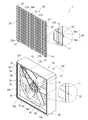
- FIG. 1 is an exploded perspective view of a fan according to the first embodiment of the present invention.
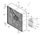
- FIG. 2 is a perspective view of the fan of FIG. 3A is a perspective view of the fan guard of the second embodiment, and FIG. 3B is a perspective view of the fan of the second embodiment.
- FIG. 4 is a partially exploded perspective view of the fan of the third embodiment.
- FIG. 5 is an explanatory diagram of a ventilation structure of a poultry house using the fan of the present embodiment.
- FIG. 6A is a side view of the fan of the modified example, and FIG. 6B is a view of the fan of the modified example as viewed from the second opening side.
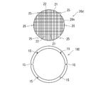
- FIG. 7 is an exploded front view showing the casing and guard of the fan of another modified example.
- 8 (a) is a perspective view of a conventional fan
- FIG. 8 (b) is a perspective view of the fan of FIG. 8 (a) with the guard opened to the left and right.
- the main configuration of the fan 1 is a rotary blade 50, a mechanism for rotationally driving the rotary blade 50, a casing 10, a removable guard 20, and a non-detachable guard 80.
- the guard 20 corresponds to the "detachable guard" of the present invention.
- the casing 10 has a cylindrical shape having a square or rectangular cross section orthogonal to the axial direction. Assuming that one of the openings at both ends of the casing 10 is the first opening 10a and the other is the second opening 10b, the guard 20 is attached to the first opening 10a.
- the first opening 10a is an intake opening and the second opening 10b is an exhaust opening.
- the rotor blade 50 is supported in a state where the central axis 51 thereof is rotatable.
- a motor 60 for rotationally driving the rotary blade 50 is housed inside the casing 10, and the output shaft 61 of the motor 60 is parallel to the central shaft 51 of the rotary blade 50.
- An endless belt 70 is wound around a pulley 65 that rotates integrally with the output shaft 61 of the motor 60 and a pulley 55 that rotates integrally with the central shaft 51 of the rotary blade 50.
- the rotation of the output shaft 61 of the motor 60 is transmitted to the central shaft 51 of the rotary blade 50 via the pulley 65, the belt 70, and the pulley 55.
- the motor 60, the pulley 65, the belt 70, and the pulley 55 correspond to the "mechanism for rotationally driving the rotary blade" of the present invention.
- an inner flange-shaped peripheral edge portion 10f is formed over the entire circumference. Since the casing 10 has a square cylinder shape, the peripheral edge portion 10f is also a quadrangle. Of the peripheral edge portion 10f, a portion extending vertically from a pair of sides extending vertically at the opening edge of the first opening 10a is referred to as a peripheral edge portion 11, and extending from a pair of sides extending left and right at the opening edge. The portion is referred to as a peripheral portion 12.
- the guard 20 includes a breathable guard body 20 m and a plurality of first locking portions 25 extending outward from the guard body 20 m.
- the guard body 20 m is formed by joining a plurality of horizontal members 21 extending in the left-right direction and spaced apart from each other and a plurality of vertical members 22 extending in the vertical direction and spaced apart from each other in a grid pattern. It is a member.
- a horizontal rod 25a extending in either the left-right direction from the guard body 20m and a vertical rod 25b extending downward from the end of the horizontal rod 25a are integrally integrated. It is a member that has become.
- the horizontal rod 25a is the base of a portion where the horizontal member 21 of the guard body 20 m is extended from the outer periphery of the guard body 20 m to the outside, and the vertical rod 25b is a bent end portion of the extended portion. be.
- the plurality of horizontal members 21 that are constituent members of the guard body 20 m some of them are extended longer than the vertical member 22 on the far right side and longer than the vertical member 22 on the leftmost side.
- the first locking portion 25 on the right side and the first locking portion 25 on the left side are formed by the respective extension portions. Therefore, the number of the first locking portion 25 on the right side and the first locking portion 25 on the left side are the same, and they are provided at the same height.
- a plurality of second locking portions 15 that engage with one of the first locking portions 25 are formed on both of the pair of left and right peripheral edges 11 in the peripheral edges 11 and 12 of the first opening 10a.
- the second locking portion 15 is formed in a cylindrical shape having a size capable of inserting the vertical rod 25b of the first locking portion 25, and is fixed to the peripheral edge portion 11 with the axial direction in the vertical direction. There is.
- the plurality of second locking portions 15 are arranged in a positional relationship corresponding to the plurality of first locking portions 25.
- a non-detachable guard 80 is fixed to the second opening 10b.
- the guard 80 is a louver type guard in which elongated plates are arranged in parallel and a gap is formed between the plates by tilting each of them.
- the guard 20 when the guard 20 is removed from the casing 10, the guard 20 is lifted upward beyond the length of the vertical rod 25b.
- the vertical rod 25b is pulled out from the second locking portion 15, the engagement between the first locking portion 25 and the second locking portion 15 is disengaged. Therefore, by moving the guard 20 to the right or left in that state, the first opening 10a can be opened.
- the guard book 20 in a state where the vertical rod 25b is pulled out from the second locking portion 15, the guard book 20 is moved toward the front slightly larger than the length of the second locking portion 15 protruding from the peripheral edge portion, and then downward.
- the first opening 10a can be opened by moving it upward.
- the guard 20 when the guard 20 is attached to the casing 10, the guard 20 is positioned so that the vertical rods 25b of the plurality of first locking portions 25 are directly above the second locking portion 15, and then the guard 20 is attached. If the vertical rod 25b is moved downward and inserted into the second locking portion 15, the first locking portion 25 is locked to the second locking portion 15 and the guard 20 can be held by the casing 10.
- the operation of attaching and detaching the guard 20 to and from the casing 10 is very easy, and even if the space in front of the fan 1, that is, the space on the side where the first opening 10a is open is narrow, there is a problem. Can be done without.
- the fan 1 having the above configuration is located in a poultry house provided with an intermediate deck when at least a part of the fans is installed at a position facing the intermediate deck in order to ventilate the internal space of the poultry house. Suitable as a fan used in.
- a plurality of cage rows 212 in which a plurality of cages 211 are continuously arranged in one horizontal direction are housed.
- the cage rows 212 are stacked in multiple stages to form a cage laminate 213, and a plurality of cage stacks 213 are arranged side by side in a direction orthogonal to the direction in which the cage rows 212 extend.
- an intermediate deck 215 is provided so as to project from the cage 211.
- the intermediate deck 215 is a passage for workers to move horizontally above the floor to facilitate the task of caring for birds in the high cage 211.
- the intermediate deck 215 provided on the wall side of the cage laminate 213 at the end and the intermediate deck 215 provided at the end of the cage row 212 in each cage laminate 213 are It overhangs the wall.
- one wall 221 of the pair of facing walls 211 and 222 is provided with an air inlet 201, and the other wall 222 is provided with an exhaust port 202.
- the air inlet 201 and the exhaust port 202 are provided with a large area of 1/2 or more of the area of the walls 221,222, respectively.
- An auxiliary air inlet 203 is provided above each of the other pair of facing walls 223.
- a plurality of large exhaust fans 250 are attached vertically and horizontally to the exhaust port 202.
- the exhaust fan 250 By operating the exhaust fan 250 to forcibly discharge air from the exhaust port 202, the internal space of the poultry house 200 is made negative pressure, and the outside through at least one of the inlet 201 and the auxiliary inlet 203.
- the poultry house 200 can be ventilated.
- the first opening 10a is an intake opening and the second opening 10b is an exhaust opening, the first opening 10a is installed on the wall 222 so as to open into the room of the poultry house 200. It is convenient for the operator to work indoors for maintenance such as repair when a malfunction occurs in the motor 60, adjustment of the tension of the belt 70, and replacement of the belt 70.
- the first opening 10a opened in the room is covered with the removable guard 20, there is no problem even if the space between the intermediate deck 215 and the fan 1 is narrow, and it is easy.
- the guard 20 can be removed from the casing 10 and attached again by a simple operation.
- the fan 1 is provided with a fastener used as an auxiliary for reinforcing the state in which the guard 20 is attached to the casing 10.
- a fastener used as an auxiliary for reinforcing the state in which the guard 20 is attached to the casing 10.
- a plurality of mounting pieces 27 extend outward from each of the upper end horizontal member 21 and the lower end horizontal member 21 in the guard body 20 m, and each mounting piece 27 has a small hole 27h penetrating. It is set up.
- a screw hole 12h is formed on the peripheral edge portion 12 of the first opening 10a in a positional relationship corresponding to the small hole 27h of the mounting piece 27.
- the guard 20 is attached to the casing 10 while facilitating the attachment / detachment of the guard 20. It can reinforce the attached state.
- Such auxiliary fasteners are not essential, and even if the fan 1 is equipped with them, the user does not necessarily have to use them.
- the guard 20 of the fan 1 of the first embodiment includes both the first locking portion 25 on the right side and the first locking portion 25 on the left side, whereas the guard 20b of the fan 2 is from the guard body 20m. It has only one of the first locking portion 25 in which the lateral rod 25a extends in the left direction and the first locking portion 25 in which the lateral rod 25a extends in the right direction from the guard body 20m.
- the case where only the first locking portion 25 on the right side is provided in the field of view when facing the peripheral portions 11 and 12 from the outside of the casing 10 is shown.
- the horizontal rod 25a of the first locking portion 25 is the base of a portion in which the horizontal member 21 of the guard main body 20m is extended to the right from the outer periphery of the guard main body 20m, and the vertical rod 25b is the extended portion. The end is bent.
- the right peripheral edge portion 11 of the pair of left and right peripheral edges 11 in the peripheral edges 11 and 12 of the first opening 10a has a positional relationship corresponding to the first locking portion 25, and the first locking portions 25 are respectively.
- a plurality of second locking portions 15 that engage with one of the above are formed.
- the one on which the first locking portion 25 is not provided (here, the left side) is fastened to the peripheral edge portion 11 by a fastener.
- a plurality of mounting pieces 28 extend outward from the leftmost vertical member 22 of the guard body 20 m, and small holes 28h are formed in each mounting piece 28.
- a screw hole 11h is formed on the left peripheral edge portion 11 in a positional relationship corresponding to the small hole 28h of the mounting piece 28. Therefore, if the screw passed through the small hole 28h is fastened to the screw hole 11h while the first locking portion 25 and the second locking portion 15 are engaged, the guard 20b covers the first opening 10a. Will be done.
- the first opening 10a when the space on the side where the first opening 10a is open is narrow, the first can be easily obtained by simply removing the fastener on the left side of the guard 20b and lifting the guard 20b upward.
- the opening 10a can be opened, and conversely, if the guard 20b is moved downward, the first opening 10a can be covered again.
- the second locking portion 15 The first opening 10a can be opened by rotating the guard 20b toward the center axis of the vertical rod 25b inserted in the above. That is, the fan 2 of the second embodiment has a method of removing the guard 20b from the casing 10 to open the first opening 10a according to the size of the space on the side where the first opening 10a is open, and the guard 20b. It is possible to open the first opening 10a while the casing 10 is attached to the casing 10.
- Such a fan 2 can also be replaced with a fan facing at least the intermediate deck 215 among the plurality of exhaust fans 250 in the ventilation structure of the poultry house 200. Further, if all of the plurality of exhaust fans 250 are replaced with the fan 2, the guard 20b is removed from the casing 10 to open the first opening 10a in the fan 2 at the position where it interferes with the intermediate deck 215, and the fan 2 does not interfere with the intermediate deck 215. The fan 2 at the position can be used properly, such as opening the first opening 10a while the guard 20b is attached to the casing 10.
- the guard 20c of the fan 3 corresponds to the guard 20 of the fan 1 of the first embodiment divided into two left and right.
- the guard 20c on the right side has only the first locking portion 25 in which the lateral rod 25a extends to the right from the guard body 20m, and the guard 20c on the left side has the lateral rod 25a extending to the left from the guard body 20m. It has only the first locking portion 25.
- the second locking portion 15 is formed on both the left and right peripheral peripheral portions 11 in the positional relationship corresponding to the first locking portion 25.
- a support column 13 is arranged in the center, and by pressing the free end of each guard 20c by the rotary fastener 130 attached to the support column 13, the guard 20c first holds the support. The state in which the opening 10a is covered is maintained.
- first opening 10a can be easily opened, and conversely, if the guard 20b is moved downward, the first opening 10a can be covered again.
- the guard 20c is centered on the vertical rod 25b inserted in the second locking portion 15 with the fastener 130 removed. By rotating the guard 20c toward you, the two guards 20c can be opened to the left and right to open the first opening 10a.
- the guard 20c is removed from the casing 10 according to the size of the space on the side where the first opening 10a is open, like the fan 2 of the second embodiment. Both a method of opening the first opening 10a and a method of opening the first opening 10a with the guard 20c attached to the casing 10 are possible.
- the guard 20c should be removed from the casing 10 and the other guard 20c should be left attached to the casing 10 to open the first opening 10a. Can be done.
- Such a fan 3 can also be used as a part or all of a plurality of exhaust fans in the ventilation structure of the poultry house 200.
- the guards 20, 20b, 20c covering the first opening 10a are removable, and the guard 80 covering the second opening 10b is non-detachable. 10b may also be covered with removable guards 20, 20b, 20c.
- the first opening 10a side is the square cylinder portion 10s and the second opening 10b side is a cone. It can be a casing 10B which is a cylindrical portion 10c of the shape.
- the guard covering the second opening 10b may be a guard 80b in which a plurality of wire rods 10w are joined at intervals, as shown in FIG. 6B, in addition to the louver type illustrated above.
- the casing 10 is rectangular and the outer shape of the guard main body 20 m is rectangular has been illustrated, but as shown in FIG. 7, the casing 10C has a cylindrical shape and the outer shape of the guard main body is circular. It can also be 20n. Even with such a shape, the guard 20d is detachably held in the casing 10 by engaging and disengaging the first locking portion 25 and the second locking portion 15, as in the above embodiment. Can be done.
Landscapes
- Engineering & Computer Science (AREA)
- Chemical & Material Sciences (AREA)
- Combustion & Propulsion (AREA)
- Mechanical Engineering (AREA)
- General Engineering & Computer Science (AREA)
- Structures Of Non-Positive Displacement Pumps (AREA)
Priority Applications (3)
| Application Number | Priority Date | Filing Date | Title |
|---|---|---|---|
| CN202080100803.8A CN115552179A (zh) | 2020-05-18 | 2020-05-18 | 风扇以及鸡舍的换气构造 |
| JP2021517879A JPWO2021234768A1 (https=) | 2020-05-18 | 2020-05-18 | |
| PCT/JP2020/019612 WO2021234768A1 (ja) | 2020-05-18 | 2020-05-18 | ファン及び鶏舎の換気構造 |
Applications Claiming Priority (1)
| Application Number | Priority Date | Filing Date | Title |
|---|---|---|---|
| PCT/JP2020/019612 WO2021234768A1 (ja) | 2020-05-18 | 2020-05-18 | ファン及び鶏舎の換気構造 |
Publications (1)
| Publication Number | Publication Date |
|---|---|
| WO2021234768A1 true WO2021234768A1 (ja) | 2021-11-25 |
Family
ID=78708200
Family Applications (1)
| Application Number | Title | Priority Date | Filing Date |
|---|---|---|---|
| PCT/JP2020/019612 Ceased WO2021234768A1 (ja) | 2020-05-18 | 2020-05-18 | ファン及び鶏舎の換気構造 |
Country Status (3)
| Country | Link |
|---|---|
| JP (1) | JPWO2021234768A1 (https=) |
| CN (1) | CN115552179A (https=) |
| WO (1) | WO2021234768A1 (https=) |
Cited By (1)
| Publication number | Priority date | Publication date | Assignee | Title |
|---|---|---|---|---|
| CN114750183A (zh) * | 2022-04-28 | 2022-07-15 | 珠海格力电器股份有限公司 | 一种空调外机风叶的定位和装配系统及其控制方法 |
Citations (7)
| Publication number | Priority date | Publication date | Assignee | Title |
|---|---|---|---|---|
| JPS5583663U (https=) * | 1978-12-05 | 1980-06-09 | ||
| JPH0238025U (https=) * | 1988-09-06 | 1990-03-13 | ||
| JPH08331997A (ja) * | 1995-06-07 | 1996-12-17 | Toyo Syst Kk | 多段ケージ陽圧鶏舎 |
| JPH10141710A (ja) * | 1996-11-06 | 1998-05-29 | Mitsubishi Electric Corp | 空気調和機の室外ユニット |
| JP2006296216A (ja) * | 2005-04-15 | 2006-11-02 | Fulta Electric Machinery Co Ltd | ハウスの防虫ネット付きの換気扇 |
| JP2007178068A (ja) * | 2005-12-28 | 2007-07-12 | Toyo System Co Ltd | ワンタッチ型フックを備えた鶏舎用換気扇 |
| JP2015062430A (ja) * | 2014-12-19 | 2015-04-09 | 達進 山田 | 鶏舎の消臭システム |
Family Cites Families (4)
| Publication number | Priority date | Publication date | Assignee | Title |
|---|---|---|---|---|
| CN205652734U (zh) * | 2016-05-17 | 2016-10-19 | 南京快联路桥建设工程有限公司 | 一种沙石输送器 |
| CN108882693B (zh) * | 2016-05-18 | 2021-03-30 | 株式会社海泰 | 鸡窝的换气方法 |
| WO2018066127A1 (ja) * | 2016-10-07 | 2018-04-12 | 三菱電機株式会社 | 空気調和装置の室外機 |
| CN208434957U (zh) * | 2017-10-31 | 2019-01-29 | 四川农业大学 | 一种家用折叠式衣柜 |
-
2020
- 2020-05-18 JP JP2021517879A patent/JPWO2021234768A1/ja active Pending
- 2020-05-18 CN CN202080100803.8A patent/CN115552179A/zh active Pending
- 2020-05-18 WO PCT/JP2020/019612 patent/WO2021234768A1/ja not_active Ceased
Patent Citations (7)
| Publication number | Priority date | Publication date | Assignee | Title |
|---|---|---|---|---|
| JPS5583663U (https=) * | 1978-12-05 | 1980-06-09 | ||
| JPH0238025U (https=) * | 1988-09-06 | 1990-03-13 | ||
| JPH08331997A (ja) * | 1995-06-07 | 1996-12-17 | Toyo Syst Kk | 多段ケージ陽圧鶏舎 |
| JPH10141710A (ja) * | 1996-11-06 | 1998-05-29 | Mitsubishi Electric Corp | 空気調和機の室外ユニット |
| JP2006296216A (ja) * | 2005-04-15 | 2006-11-02 | Fulta Electric Machinery Co Ltd | ハウスの防虫ネット付きの換気扇 |
| JP2007178068A (ja) * | 2005-12-28 | 2007-07-12 | Toyo System Co Ltd | ワンタッチ型フックを備えた鶏舎用換気扇 |
| JP2015062430A (ja) * | 2014-12-19 | 2015-04-09 | 達進 山田 | 鶏舎の消臭システム |
Cited By (2)
| Publication number | Priority date | Publication date | Assignee | Title |
|---|---|---|---|---|
| CN114750183A (zh) * | 2022-04-28 | 2022-07-15 | 珠海格力电器股份有限公司 | 一种空调外机风叶的定位和装配系统及其控制方法 |
| CN114750183B (zh) * | 2022-04-28 | 2023-09-19 | 珠海格力电器股份有限公司 | 一种空调外机风叶的定位和装配系统及其控制方法 |
Also Published As
| Publication number | Publication date |
|---|---|
| JPWO2021234768A1 (https=) | 2021-11-25 |
| CN115552179A (zh) | 2022-12-30 |
Similar Documents
| Publication | Publication Date | Title |
|---|---|---|
| EP1621825B1 (en) | Indoor unit for air conditioner | |
| JP2007303770A (ja) | 空気調和装置 | |
| US20100071325A1 (en) | Air filtration system and method | |
| US9903600B2 (en) | Wind direction adjusting device of air-conditioning apparatus and air-conditioning apparatus | |
| KR101038347B1 (ko) | 송풍기 | |
| WO2021234768A1 (ja) | ファン及び鶏舎の換気構造 | |
| CN218379655U (zh) | 空气调节设备 | |
| JP4914020B2 (ja) | ハウスの防虫ネット付きの換気扇 | |
| KR20130005236U (ko) | 공기조화용 환기구 | |
| JP2012097930A (ja) | ダクト型空気調和機 | |
| KR200444859Y1 (ko) | 다용도 냉각장치 | |
| CN216244604U (zh) | 净化模块及风管机 | |
| JP3154696U (ja) | 畜舎の換気装置 | |
| KR100890568B1 (ko) | 다단 송풍휀을 갖는 온풍기 | |
| KR200481951Y1 (ko) | 후크 결합 구조와 2중 커버 개폐식 그릴을 갖는 전열교환기 | |
| JP4751167B2 (ja) | 換気扇の構造 | |
| KR102602210B1 (ko) | 환풍기 커버 구조 | |
| JPH05164374A (ja) | ダクト用換気扇 | |
| JP2006296216A (ja) | ハウスの防虫ネット付きの換気扇 | |
| JP6035983B2 (ja) | 送風装置 | |
| KR100608266B1 (ko) | 환기장치 | |
| KR100714644B1 (ko) | 2중 비닐하우스용 자동 통풍기 | |
| KR200152140Y1 (ko) | 공기조화기용 실내기의 가동식콘트롤장치 | |
| JP2007093040A (ja) | 空気調和機 | |
| JP5527342B2 (ja) | 換気装置 |
Legal Events
| Date | Code | Title | Description |
|---|---|---|---|
| ENP | Entry into the national phase |
Ref document number: 2021517879 Country of ref document: JP Kind code of ref document: A |
|
| 121 | Ep: the epo has been informed by wipo that ep was designated in this application |
Ref document number: 20936186 Country of ref document: EP Kind code of ref document: A1 |
|
| NENP | Non-entry into the national phase |
Ref country code: DE |
|
| 32PN | Ep: public notification in the ep bulletin as address of the adressee cannot be established |
Free format text: NOTING OF LOSS OF RIGHTS PURSUANT TO RULE 112(1) EPC (EPO FORM 1205A DATED 22/02/2023) |
|
| 122 | Ep: pct application non-entry in european phase |
Ref document number: 20936186 Country of ref document: EP Kind code of ref document: A1 |