WO2021230176A1 - Foret et procédé de fabrication de pièce découpée - Google Patents
Foret et procédé de fabrication de pièce découpée Download PDFInfo
- Publication number
- WO2021230176A1 WO2021230176A1 PCT/JP2021/017620 JP2021017620W WO2021230176A1 WO 2021230176 A1 WO2021230176 A1 WO 2021230176A1 JP 2021017620 W JP2021017620 W JP 2021017620W WO 2021230176 A1 WO2021230176 A1 WO 2021230176A1
- Authority
- WO
- WIPO (PCT)
- Prior art keywords
- flank
- blade
- drill
- cutting edge
- clearance angle
- Prior art date
Links
Images


Classifications
-
- B—PERFORMING OPERATIONS; TRANSPORTING
- B23—MACHINE TOOLS; METAL-WORKING NOT OTHERWISE PROVIDED FOR
- B23B—TURNING; BORING
- B23B51/00—Tools for drilling machines
- B23B51/02—Twist drills
-
- B—PERFORMING OPERATIONS; TRANSPORTING
- B23—MACHINE TOOLS; METAL-WORKING NOT OTHERWISE PROVIDED FOR
- B23B—TURNING; BORING
- B23B35/00—Methods for boring or drilling, or for working essentially requiring the use of boring or drilling machines; Use of auxiliary equipment in connection with such methods
-
- B—PERFORMING OPERATIONS; TRANSPORTING
- B23—MACHINE TOOLS; METAL-WORKING NOT OTHERWISE PROVIDED FOR
- B23B—TURNING; BORING
- B23B2251/00—Details of tools for drilling machines
- B23B2251/04—Angles, e.g. cutting angles
- B23B2251/048—Radial clearance angles
-
- B—PERFORMING OPERATIONS; TRANSPORTING
- B23—MACHINE TOOLS; METAL-WORKING NOT OTHERWISE PROVIDED FOR
- B23B—TURNING; BORING
- B23B2251/00—Details of tools for drilling machines
- B23B2251/08—Side or plan views of cutting edges
- B23B2251/085—Discontinuous or interrupted cutting edges
-
- B—PERFORMING OPERATIONS; TRANSPORTING
- B23—MACHINE TOOLS; METAL-WORKING NOT OTHERWISE PROVIDED FOR
- B23B—TURNING; BORING
- B23B2251/00—Details of tools for drilling machines
- B23B2251/14—Configuration of the cutting part, i.e. the main cutting edges
-
- B—PERFORMING OPERATIONS; TRANSPORTING
- B23—MACHINE TOOLS; METAL-WORKING NOT OTHERWISE PROVIDED FOR
- B23B—TURNING; BORING
- B23B2251/00—Details of tools for drilling machines
- B23B2251/18—Configuration of the drill point
- B23B2251/182—Web thinning
-
- B—PERFORMING OPERATIONS; TRANSPORTING
- B23—MACHINE TOOLS; METAL-WORKING NOT OTHERWISE PROVIDED FOR
- B23B—TURNING; BORING
- B23B2251/00—Details of tools for drilling machines
- B23B2251/20—Number of cutting edges
- B23B2251/202—Three cutting edges
Definitions
- the present disclosure generally relates to a method for manufacturing a drill and a machined material used for drilling a work material.
- the drill may include a tip exchange type drill and a solid drill.
- Patent Document 1 Japanese Patent Application Laid-Open No. 2010-125592
- Patent Document 2 International Publication No. 2010/0868988
- the drill described in Patent Document 1 has a cutting edge and a chamfering edge located on the outer peripheral side with respect to the cutting edge.
- the drill described in Patent Document 2 has a first cutting edge and a second cutting edge located on the outer peripheral side with respect to the first cutting edge.
- the unrestricted one-sided drill of the present disclosure has a body extending from the first end to the second end along the axis of rotation.
- the main body has an outer peripheral surface, a cutting edge located on the side of the first end, a flank located along the cutting edge on the rear side in the rotation direction of the rotating shaft, and the second from the cutting edge. It has a groove extending towards the edge.
- the cutting blade has a first blade, a second blade extending from the first blade toward the outer peripheral surface, and a third blade extending from the second blade toward the outer peripheral surface.
- the flanks are a first flank located along the first blade and having a first flank angle, a second flank located along the second blade and having a second flank angle, and the above. It has a third flank, which is located along the third blade and has a third flank angle.
- the second clearance angle is smaller than the first clearance angle and the third clearance angle.
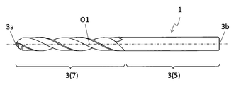
- FIG. 3 is a perspective view showing an unrestricted one-sided drill of the present disclosure.
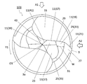
- FIG. 3 is a plan view of the drill shown in FIG. 1 as viewed from the side of the first end. It is a side view which looked at the drill shown in FIG. 2 from the A1 direction. It is a side view which saw the drill shown in FIG. 2 from the A2 direction. It is an enlarged view which expanded the area B1 shown in FIG. It is an enlarged view which expanded the area B2 shown in FIG.
- FIG. 6 is a cross-sectional view of a cross section of VII-VII shown in FIG. It is sectional drawing of the VIII-VIII cross section shown in FIG. It is sectional drawing of the IX-IX cross section shown in FIG.
- the one-sided drill 1 without limitation of the present disclosure will be described in detail with reference to the drawings.
- the drill 1 may include any component not shown in each referenced figure.
- the dimensions of the members in each drawing do not faithfully represent the dimensions of the actual constituent members and the dimensional ratio of each member.
- a solid drill may be shown as an example of the drill 1.
- the drill 1 is not limited to a solid drill, and may be, for example, a tip exchange type drill.
- the drill 1 may have a main body 3 as in the non-limiting example shown in FIGS. 1 to 4.
- the main body 3 may extend from the first end 3a toward the second end 3b along the rotation axis O1.
- the main body 3 may have a rod shape extending from the first end 3a to the second end 3b along the rotation axis O1.
- the first end 3a is called the "tip” and the second end 3b is called the "rear end”.
- the main body 3 can rotate around the rotation axis O1.
- the arrow Y1 in FIG. 1 and the like indicates the rotation direction of the rotation axis O1.
- the main body 3 may have a shank portion 5 and a cutting portion 7.
- the shank portion 5 can be gripped by the rotating spindle of the machine tool.
- the shank portion 5 may be designed according to the shape of the spindle in the machine tool.
- the cutting portion 7 may be located on the side of the first end 3a with respect to the shank portion 5.
- the cutting portion 7 can come into contact with the work material and can play a major role in the cutting process (for example, drilling process) of the work material.
- the outer diameter D of the cutting portion 7 is not limited to a specific value.
- the maximum value of the outer diameter D may be set to 2 to 50 mm.
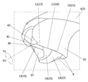
- the main body 3 may have an outer peripheral surface 9, a cutting edge 11, a flank 13 and a groove 15, as in the case of the unrestricted example shown in FIG.
- the cutting edge 11 may be located on the side of the first end 3a.
- the flank 13 may be located along the cutting edge 11 on the rear side of the rotation axis O1 in the rotation direction Y1.
- the groove 15 may extend from the cutting edge 11 toward the second end 3b.
- the outer peripheral surface 9, the cutting edge 11, the flank 13 and the groove 15 may be located at the cutting portion 7.
- the cutting edge 11 can be used for cutting the work material in the cutting process.
- the cutting blade 11 may have a first blade 17, a second blade 19, and a third blade 21.
- the first blade 17, the second blade 19, and the third blade 21 are also referred to as a main cutting blade.
- the second blade 19 may extend from the first blade 17 toward the outer peripheral surface 9.
- the third blade 21 may extend from the second blade 19 toward the outer peripheral surface 9.
- the first blade 17 may be separated from the rotation shaft O1.
- the second blade 19 may be inclined with respect to the first blade 17 when viewed from a direction orthogonal to the rotation axis O1 and may be a third blade.
- the blade 21 may be tilted with respect to the second blade 19.
- the third blade 21 may be connected to the outer peripheral surface 9.
- the number of the first blades 17 may be one or a plurality. When the number of the first blades 17 is plural, the number may be 2 to 5. These points are the same for the second blade 19 and the third blade 21. As in the non-limiting example shown in FIG. 2, the drill 1 may be a so-called two-flute type drill.
- the plurality of first blades 17 may be positioned so as to be rotationally symmetric with respect to the rotation axis O1 in the front view from the side of the first end 3a.
- the two first blades 17 are the rotation axes in the front view from the side of the first end 3a. It may be positioned so as to be rotationally symmetric with respect to O1. In this case, the straightness of the drill 1 when cutting the work material is high.
- the first blade 17 may have a linear shape or a curved shape when viewed from the side of the first end 3a, or may have a shape in which a linear shape and a curved shape are combined. These points are the same for the second blade 19 and the third blade 21.
- the shapes of the first blade 17, the second blade 19, and the third blade 21 may be the same or different when viewed from the side of the first end 3a.
- the first blade 17 may have a concave curved shape in a front view from the side of the first end 3a.
- the second blade 19 may have a linear shape.
- the third blade 21 may have a convex curved shape.
- the lengths of the first blade 17, the second blade 19, and the third blade 21 may be the same or different.
- the length of the second blade 19 may be longer than the length of the first blade 17.
- the length of the third blade 21 may be longer than the length of the second blade 19.
- the third blade 21 may be the longest in the cutting blade 11.
- the groove 15 can be used to discharge the chips generated by the cutting edge 11 to the outside.
- the groove 15 may extend parallel to the axis of rotation O1 or may extend spirally around the axis of rotation O1.
- the number of grooves 15 may be one or may be plural.
- the groove 15 may be connected to the cutting edge 11. In this case, the bite to the work material is high. Further, a rake surface connecting the groove 15 and the cutting edge 11 may be located. In this case, the discharge direction of the chips generated by the cutting edge 11 is likely to be stable. From the viewpoint of smoothly discharging chips to the outside, the groove 15 may have a concave curved shape in a cross section orthogonal to the rotation axis O1.
- the depth of the groove 15 is not limited to a specific value.
- the depth of the groove 15 may be set to 10 to 40% with respect to the outer diameter of the main body 3 (cutting portion 7).
- the depth of the groove 15 may be a value obtained by subtracting the distance between the bottom of the groove 15 and the rotation axis O1 from the radius of the main body 3 (cutting portion 7) in the cross section orthogonal to the rotation axis O1.
- the bottom may be the portion of the groove 15 closest to the rotation axis O1.
- the flank 13 may have a first flank 23, a second flank 25, and a third flank 27.
- the first flank 23 may be located along the first blade 17.
- the second flank 25 may be located along the second blade 19.
- the third flank 27 may be located along the third blade 21.
- the first flank 23 may be connected to the first blade 17 or may be separated from the first blade 17.
- the second flank 25 may be connected to the second blade 19 or may be separated from the second blade 19.
- the third flank 27 may be connected to the third blade 21 or may be separated from the third blade 21.
- the first flank 23 may be connected to the first blade 17, and the second flank 25 may be connected to the second blade 19.
- the 3 flank 27 may be connected to the 3rd blade 21.
- the flank 13 may have a "sleep angle".
- the "clearance angle” may be defined as follows. First, a cross section orthogonal to the cutting edge 11 may be shown at a target portion of the cutting edge 11. For example, as in the case of the non-limiting example shown in FIGS. 6 to 9, a cross section orthogonal to each of the first blade 17, the second blade 19, and the third blade 21 may be shown.
- the drill 1 When the drill 1 is a so-called two-blade type drill, it may have two portions such as the first blade 17.
- "a" is added to the code indicating one part and "b" is added to the code indicating the other part in FIGS. 6 to 9. .
- one first blade 17 is indicated by reference numeral 17a
- the other first blade 17 is indicated by reference numeral 17b.
- a virtual straight line passing through the cutting edge 11 and in contact with the rotation locus of the cutting edge 11 may be used as the reference line L1.
- the virtual straight line tangent to the rotation locus of this end may be set as the reference line L1.
- the virtual straight line in contact with the end portion of the flank 13 on the side of the cutting edge 11 may be the evaluation line L2. Then, the angle at which the reference line L1 and the evaluation line L2 intersect may be set as a “clearance angle”.
- the first flank 23 may have a first flank angle ⁇ 1 as in the unrestricted example shown in FIG.
- the second flank 25 may have a second flank angle ⁇ 2, as in the unrestricted example shown in FIG.
- the third flank 27 may have a third flank angle ⁇ 3, as in the unrestricted example shown in FIG.
- the second clearance angle ⁇ 2 may be smaller than the first clearance angle ⁇ 1 and the third clearance angle ⁇ 3.
- the first clearance angle ⁇ 1 is relatively large, the cutting edge of the first blade 17 relatively close to the rotation axis O1 can be sharpened, so that the cutting resistance tends to be small and the straight running stability of the drill 1 is high.
- the third clearance angle ⁇ 3 is relatively large, the cutting edge of the third blade 21 which is relatively close to the outer peripheral surface 9 can be sharpened, so that burrs are less likely to occur in the machined hole.
- the second clearance angle ⁇ 2 is relatively small, it is easy to control the movement of the drill 1 in the direction along the rotation axis O1.
- the thrust resistance changes abruptly at the moment of penetrating the work material, it is difficult to control the movement of the drill 1 in the direction along the rotation axis O1.
- the second clearance angle ⁇ 2 is relatively small, the second clearance surface 25 easily comes into contact with the work material, so that it is easy to control the movement of the drill 1 in the direction along the rotation axis O1. Therefore, when the second clearance angle ⁇ 2 is smaller than the first clearance angle ⁇ 1 and the third clearance angle ⁇ 3, the accuracy of the machined hole is high.
- the first clearance angle ⁇ 1 may be the same as or different from the third clearance angle ⁇ 3.
- the thrust resistance is efficiently increased at the tip portion where the depth of cut per rotation is large. It tends to be small. Therefore, for example, straight-line stability is high even for a work material having a large cutting resistance.
- the third clearance surface 27 located on the outer peripheral side is machined as compared with the first clearance surface 23 located near the rotation axis O1. Hard to come in contact with the material. That is, even if the flanks come into contact with the work material, the first flank 23 located closer to the rotation axis O1 is more likely to come into contact with the work material as compared with the third flank 27. Therefore, even when chatter vibration occurs due to the flank contacting the work material, it is easy to suppress the chatter vibration to a small extent.
- the first clearance angle ⁇ 1, the second clearance angle ⁇ 2, and the third clearance angle ⁇ 3 are not limited to specific values.
- the first clearance angle ⁇ 1 may be set to 5 to 15 °.
- the second clearance angle ⁇ 2 may be set to 5 ° or less.
- the third clearance angle ⁇ 3 may be set to 5 to 20 °.
- the first flank 23 may be a flat surface, and the second flank 25 and the third flank 27 may be curved, respectively. In this case, the movement of the drill 1 is easily controlled.
- the tip angle of the drill 1 is easily suppressed to a small value, so that the drill 1 easily bites into the work material.
- the drill 1 tends to swing.
- the second flank 25 and the third flank 27 are curved surfaces, the second flank 25 and the third flank 27 come into contact with the work material when the drill 1 penetrates the work material. Easy to do. Therefore, the runout of the drill 1 is suppressed, and it is easy to maintain the straight running stability.
- the plane may be a plane in general, and does not have to be a plane in a strict sense. This point is the same for curved surfaces.
- the second flank 25 and the third flank 27 may each have a convex curved surface.
- the boundary between the first flank 23 and the second flank 25 may be the first boundary 29.
- the first boundary 29 may approach the outer peripheral surface 9 from the cutting blade 11 (first blade 17 and second blade 19) toward the rear in the rotation direction Y1. In this case, it is easy to suppress chatter vibration caused by the flank contacting the work material. This is because even if the flanks come into contact with the work material, the first flank 23 located closer to the rotation axis O1 is more likely to come into contact with the work material than the second flank 25. Is. As a result, it is easy to suppress chatter vibration while ensuring the length of the second blade 19.
- the first boundary 29 may have a curved shape.
- the boundary between the second flank 25 and the third flank 27 may be the second boundary 31.
- the second boundary 31 may be separated from the outer peripheral surface 9 from the cutting blade 11 (the second blade 19 and the third blade 21) toward the rear in the rotation direction Y1.
- the second boundary 31 may have a curved shape.
- the radius of curvature at the second boundary 31 of the curved shape may be smaller than the radius of curvature at the first boundary 29 of the curved shape.
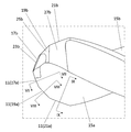
- the second flank 25 has a first region 33 in which the width W in the radial direction of the rotation axis O1 becomes narrower toward the rear of the rotation direction Y1 and a first region 33. It may have a second region 35 which is located behind the rotation direction Y1 and whose width W becomes wider toward the rear of the rotation direction Y1. In this case, when the second flank 25 comes into contact with the work material, the influence of heat generated in the first region 33 can be minimized, and the movement of the drill 1 can be effectively controlled. Will be.
- the second area 35 may be connected to the first area 33.
- the maximum value of the width W in the first region 33 may be the same as or different from the maximum value of the width W in the second region 35.
- the maximum value of the width W in the first region 33 is larger than the maximum value of the width W in the second region 35, heat generation in the second region 35 is suppressed. easy. This is because even if the second flank 25 comes into contact with the work material when the drill 1 penetrates the work material, it is possible to prevent the second region 35 from excessively contacting the work material.
- the second flank 25 may be connected to the first flank 23.
- the third flank 27 may be connected to the second flank 25 or may be connected to the outer peripheral surface 9.
- the areas of the first flank 23, the second flank 25, and the third flank 27 may be the same or different.
- the area of the second flank 25 may be larger than the area of the first flank 23.
- the area of the third flank 27 may be larger than the area of the second flank 25.
- the area of the third flank 27 may be the largest on the flank 13.
- the flank 13 may further have a fourth flank 37 that is located behind the rotation direction Y1 along the first flank 23 and is inclined with respect to the first flank 23.
- the fourth flank 37 may also be referred to as the third flank.
- the fourth flank 37 may be connected to the first flank 23 or may be connected to the second flank 25.
- the fourth flank 37 may be flat.
- the inclination angle of the fourth flank 37 is not limited to a specific value.
- the inclination angle of the fourth flank 37 may be set to 15 to 35 °.
- the cutting edge 11 may have a chisel edge 39.
- the chisel edge 39 can serve to bite into the work material.
- the chisel edge 39 may be located closest to the rotation axis O1 on the cutting edge 11. Further, the chisel edge 39 may intersect with the rotation axis O1.
- the chisel edge 39 may be located between the two first flanks 23.
- the chisel edge 39 may be located at the intersection of the two first flanks 23.
- the chisel edge 39 may be the shortest in the cutting edge 11.
- the chisel edge 39 may have a linear shape when viewed from the side of the first end 3a.
- the cutting edge 11 may have a thinning edge 41.
- the thinning edge 41 may be located closer to the rotation axis O1 than the first blade 17. Further, the thinning edge 41 may be located between the first blade 17 and the chisel edge 39. The thinning edge 41 may be connected to the first blade 17 or may be connected to the chisel edge 39. The length of the thinning edge 41 may be shorter than the length of the first blade 17.
- the thinning edge 41 may have a linear shape when viewed from the side of the first end 3a.
- the main body 3 may have a gash 43 located between the thinning edge 41 and the groove 15.
- the gash 43 may be located along the thinning edge 41 on the front side in the rotation direction Y1.
- Examples of the material of the main body 3 include cemented carbide and cermet.
- Examples of the composition of the cemented carbide include WC-Co, WC-TiC-Co and WC-TiC-TaC-Co.
- WC, TiC and TaC may be hard particles, and Co may be a bonded phase.
- the cermet may be a sintered composite material in which a metal is composited with a ceramic component.
- examples of the cermet may be a titanium compound containing titanium carbide (TiC) or titanium nitride (TiN) as a main component.
- TiC titanium carbide
- TiN titanium nitride
- the above materials are not limited to these materials, and the main body 3 is not limited to these materials.
- the surface of the main body 3 may be coated with a coating using a chemical vapor deposition (CVD) method or a physical vapor deposition (PVD) method.
- CVD chemical vapor deposition
- PVD physical vapor deposition
- the composition of the coating include titanium carbide (TiC), titanium nitride (TiN), titanium carbonitride (TiCN), alumina (Al 2 O 3 ) and the like.
- the machined object 101 may be manufactured by cutting the work material 103.
- the method for manufacturing the machined product 101 may include the following steps (1) to (4).
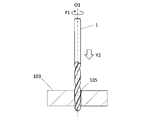
- a step of arranging the drill 1 above the prepared work material 103 (see FIG. 10).
- a step of rotating the drill 1 in the direction of the arrow Y1 around the rotation axis O1 and bringing the drill 1 closer to the work material 103 in the Y2 direction (see FIG. 10).
- the work material 103 may be fixed on the table of the machine tool to which the drill 1 is attached, and the work material 103 may be brought close to the work material 103 while the drill 1 is rotated. good.
- the work material 103 and the drill 1 may be relatively close to each other, and for example, the work material 103 may be brought close to the drill 1.
- cutting may be performed so that at least a part of the cutting portion 7 in the main body 3 is located in the machined hole 105. Further, in the step (3), the shank portion 5 in the main body 3 may be set to be located outside the machined hole 105. From the viewpoint of obtaining a good finished surface, a part of the cutting portion 7 on the side of the second end 3b may be set to be located outside the machined hole 105. It is possible to make a part of the above function as a margin region for chip discharge, and it is possible to exhibit excellent chip discharge property through the region.
- a step of separating the drill 1 from the work material 103 in the Y3 direction (see FIG. 12).
- the work material 103 and the drill 1 may be relatively separated from each other, and for example, the work material 103 may be separated from the drill 1.
- the state in which the drill 1 is rotated is maintained. While doing so, the step of bringing the cutting edge 11 of the drill 1 into contact with different parts of the work material 103 may be repeated.
- Examples of the material of the work material 103 include aluminum, carbon steel, alloy steel, stainless steel, cast iron, and non-ferrous metal.
- Drill 3 Main body 3a ... First end (tip) 3b ... 2nd end (rear end) 5 ... Shank part 7 ... Cutting part 9 ... Outer peripheral surface 11 ... Cutting blade 13 ... Escape surface 15 ... Groove 17 ... 1st blade 19 ... 2nd blade 21 ... 3rd blade 23 ... 1st flank 25 ... 2nd flank 27 ... 3rd flank 29 ... 1st boundary 31 ... 2nd boundary 33 ... 1st Area 35 ... 2nd area 37 ... 4th flank 39 ... Chisel edge 41 ... Thinning edge 43 ... Gash 101 ... Machined work 103 ... Work material 105 ...
Abstract
Un foret selon un aspect non limitatif de la présente divulgation comprend un corps qui s'étend d'une première extrémité à une seconde extrémité le long d'un axe de rotation. Le corps comporte : une surface circonférentielle externe ; un bord de coupe qui est situé sur le premier côté d'extrémité ; un flanc qui est situé le long du bord de coupe sur le côté arrière dans une direction de rotation autour de l'axe de rotation ; et une rainure qui s'étend depuis le bord de coupe vers la seconde extrémité. Le bord de coupe comporte : une première lame ; une deuxième lame qui s'étend à partir de la première lame vers la surface circonférentielle externe ; et une troisième lame qui s'étend à partir de la deuxième lame vers la surface circonférentielle externe. Le flanc comporte : un premier flanc qui est situé le long de la première lame et a un premier angle de dépouille ; un deuxième flanc qui est situé le long de la deuxième lame et qui présente un deuxième angle de dépouille ; et un troisième flanc qui est situé le long de la troisième lame et qui présente un troisième angle de dépouille. Le deuxième angle de dépouille est inférieur au premier angle de dépouille et au troisième angle de dépouille.
Priority Applications (4)
| Application Number | Priority Date | Filing Date | Title |
|---|---|---|---|
| CN202180032930.3A CN115515740A (zh) | 2020-05-11 | 2021-05-10 | 钻头以及切削加工物的制造方法 |
| DE112021002713.1T DE112021002713T5 (de) | 2020-05-11 | 2021-05-10 | Bohrer und verfahren zur herstellung eines maschinell bearbeiteten produkts |
| JP2022521889A JP7386339B2 (ja) | 2020-05-11 | 2021-05-10 | ドリル及び切削加工物の製造方法 |
| US17/998,041 US20230173594A1 (en) | 2020-05-11 | 2021-05-10 | Drill and method for manufacturing machined product |
Applications Claiming Priority (2)
| Application Number | Priority Date | Filing Date | Title |
|---|---|---|---|
| JP2020-082959 | 2020-05-11 | ||
| JP2020082959 | 2020-05-11 |
Publications (1)
| Publication Number | Publication Date |
|---|---|
| WO2021230176A1 true WO2021230176A1 (fr) | 2021-11-18 |
Family
ID=78525800
Family Applications (1)
| Application Number | Title | Priority Date | Filing Date |
|---|---|---|---|
| PCT/JP2021/017620 WO2021230176A1 (fr) | 2020-05-11 | 2021-05-10 | Foret et procédé de fabrication de pièce découpée |
Country Status (5)
| Country | Link |
|---|---|
| US (1) | US20230173594A1 (fr) |
| JP (1) | JP7386339B2 (fr) |
| CN (1) | CN115515740A (fr) |
| DE (1) | DE112021002713T5 (fr) |
| WO (1) | WO2021230176A1 (fr) |
Citations (5)
| Publication number | Priority date | Publication date | Assignee | Title |
|---|---|---|---|---|
| US20100135741A1 (en) * | 2008-12-03 | 2010-06-03 | Black & Decker Inc. | Drill Bit Including One Piece Cutting Head |
| JP2010155289A (ja) * | 2008-12-26 | 2010-07-15 | Fuji Heavy Ind Ltd | ドリル |
| WO2014069453A1 (fr) * | 2012-10-29 | 2014-05-08 | 京セラ株式会社 | Laminoir à extrémité sphérique |
| US20170066062A1 (en) * | 2015-09-08 | 2017-03-09 | Mitsubishi Materials Corporation | Drill |
| WO2019039001A1 (fr) * | 2017-08-22 | 2019-02-28 | 住友電工ハードメタル株式会社 | Outil de coupe rotatif et son procédé de fabrication |
Family Cites Families (2)
| Publication number | Priority date | Publication date | Assignee | Title |
|---|---|---|---|---|
| WO2010086988A1 (fr) | 2009-01-29 | 2010-08-05 | オーエスジー株式会社 | Foret isocèle |
| JP7139910B2 (ja) | 2018-11-21 | 2022-09-21 | トヨタ自動車株式会社 | パワートレーンシステム |
-
2021
- 2021-05-10 WO PCT/JP2021/017620 patent/WO2021230176A1/fr active Application Filing
- 2021-05-10 JP JP2022521889A patent/JP7386339B2/ja active Active
- 2021-05-10 DE DE112021002713.1T patent/DE112021002713T5/de active Pending
- 2021-05-10 CN CN202180032930.3A patent/CN115515740A/zh active Pending
- 2021-05-10 US US17/998,041 patent/US20230173594A1/en active Pending
Patent Citations (5)
| Publication number | Priority date | Publication date | Assignee | Title |
|---|---|---|---|---|
| US20100135741A1 (en) * | 2008-12-03 | 2010-06-03 | Black & Decker Inc. | Drill Bit Including One Piece Cutting Head |
| JP2010155289A (ja) * | 2008-12-26 | 2010-07-15 | Fuji Heavy Ind Ltd | ドリル |
| WO2014069453A1 (fr) * | 2012-10-29 | 2014-05-08 | 京セラ株式会社 | Laminoir à extrémité sphérique |
| US20170066062A1 (en) * | 2015-09-08 | 2017-03-09 | Mitsubishi Materials Corporation | Drill |
| WO2019039001A1 (fr) * | 2017-08-22 | 2019-02-28 | 住友電工ハードメタル株式会社 | Outil de coupe rotatif et son procédé de fabrication |
Also Published As
| Publication number | Publication date |
|---|---|
| DE112021002713T5 (de) | 2023-02-23 |
| US20230173594A1 (en) | 2023-06-08 |
| JP7386339B2 (ja) | 2023-11-24 |
| CN115515740A (zh) | 2022-12-23 |
| JPWO2021230176A1 (fr) | 2021-11-18 |
Similar Documents
| Publication | Publication Date | Title |
|---|---|---|
| JP6892503B2 (ja) | 回転工具 | |
| JP7168673B2 (ja) | 切削インサート、回転工具及び切削加工物の製造方法 | |
| JP7055865B2 (ja) | 回転工具及び切削加工物の製造方法 | |
| US11351617B2 (en) | Rotating tool | |
| WO2018180775A1 (fr) | Outil tournant | |
| JP7103933B2 (ja) | 切削インサート、回転工具及び切削加工物の製造方法 | |
| JP7142681B2 (ja) | ドリル及び切削加工物の製造方法 | |
| JP6882517B2 (ja) | 回転工具 | |
| JP6941047B2 (ja) | 回転工具及び切削加工物の製造方法 | |
| JP7417707B2 (ja) | エンドミル及び切削加工物の製造方法 | |
| WO2021230176A1 (fr) | Foret et procédé de fabrication de pièce découpée | |
| JPWO2019088013A1 (ja) | ドリル及び切削加工物の製造方法 | |
| WO2021153599A1 (fr) | Outil tournant et procédé de fabrication de pièces découpées | |
| WO2019139075A1 (fr) | Foret et procédé de production d'article coupé | |
| JP7279163B2 (ja) | 回転工具及び切削加工物の製造方法 | |
| WO2021020259A1 (fr) | Foret et procédé de fabrication d'une pièce découpée | |
| WO2021117822A1 (fr) | Foret et procédé de fabrication de pièce découpée | |
| JP7465980B2 (ja) | 回転工具及び切削加工物の製造方法 | |
| WO2023181814A1 (fr) | Foret, et procédé de fabrication de pièce découpée | |
| JP2024021376A (ja) | ドリル及び切削加工物の製造方法 | |
| JP2020069558A (ja) | 回転工具及び切削加工物の製造方法 | |
| JP2021100772A (ja) | 回転工具及び切削加工物の製造方法 | |
| JP2019217616A (ja) | 回転工具及び切削加工物の製造方法 | |
| JP2001341024A (ja) | ステンレス切削用ドリル |
Legal Events
| Date | Code | Title | Description |
|---|---|---|---|
| 121 | Ep: the epo has been informed by wipo that ep was designated in this application |
Ref document number: 21803551 Country of ref document: EP Kind code of ref document: A1 |
|
| ENP | Entry into the national phase |
Ref document number: 2022521889 Country of ref document: JP Kind code of ref document: A |
|
| 122 | Ep: pct application non-entry in european phase |
Ref document number: 21803551 Country of ref document: EP Kind code of ref document: A1 |