WO2021230176A1 - Drill and method for manufacturing cut workpiece - Google Patents
Drill and method for manufacturing cut workpiece Download PDFInfo
- Publication number
- WO2021230176A1 WO2021230176A1 PCT/JP2021/017620 JP2021017620W WO2021230176A1 WO 2021230176 A1 WO2021230176 A1 WO 2021230176A1 JP 2021017620 W JP2021017620 W JP 2021017620W WO 2021230176 A1 WO2021230176 A1 WO 2021230176A1
- Authority
- WO
- WIPO (PCT)
- Prior art keywords
- flank
- blade
- drill
- cutting edge
- clearance angle
- Prior art date
Links
Images


Classifications
-
- B—PERFORMING OPERATIONS; TRANSPORTING
- B23—MACHINE TOOLS; METAL-WORKING NOT OTHERWISE PROVIDED FOR
- B23B—TURNING; BORING
- B23B51/00—Tools for drilling machines
- B23B51/02—Twist drills
-
- B—PERFORMING OPERATIONS; TRANSPORTING
- B23—MACHINE TOOLS; METAL-WORKING NOT OTHERWISE PROVIDED FOR
- B23B—TURNING; BORING
- B23B35/00—Methods for boring or drilling, or for working essentially requiring the use of boring or drilling machines; Use of auxiliary equipment in connection with such methods
-
- B—PERFORMING OPERATIONS; TRANSPORTING
- B23—MACHINE TOOLS; METAL-WORKING NOT OTHERWISE PROVIDED FOR
- B23B—TURNING; BORING
- B23B2251/00—Details of tools for drilling machines
- B23B2251/04—Angles, e.g. cutting angles
- B23B2251/048—Radial clearance angles
-
- B—PERFORMING OPERATIONS; TRANSPORTING
- B23—MACHINE TOOLS; METAL-WORKING NOT OTHERWISE PROVIDED FOR
- B23B—TURNING; BORING
- B23B2251/00—Details of tools for drilling machines
- B23B2251/08—Side or plan views of cutting edges
- B23B2251/085—Discontinuous or interrupted cutting edges
-
- B—PERFORMING OPERATIONS; TRANSPORTING
- B23—MACHINE TOOLS; METAL-WORKING NOT OTHERWISE PROVIDED FOR
- B23B—TURNING; BORING
- B23B2251/00—Details of tools for drilling machines
- B23B2251/14—Configuration of the cutting part, i.e. the main cutting edges
-
- B—PERFORMING OPERATIONS; TRANSPORTING
- B23—MACHINE TOOLS; METAL-WORKING NOT OTHERWISE PROVIDED FOR
- B23B—TURNING; BORING
- B23B2251/00—Details of tools for drilling machines
- B23B2251/18—Configuration of the drill point
- B23B2251/182—Web thinning
-
- B—PERFORMING OPERATIONS; TRANSPORTING
- B23—MACHINE TOOLS; METAL-WORKING NOT OTHERWISE PROVIDED FOR
- B23B—TURNING; BORING
- B23B2251/00—Details of tools for drilling machines
- B23B2251/20—Number of cutting edges
- B23B2251/202—Three cutting edges
Definitions
- the present disclosure generally relates to a method for manufacturing a drill and a machined material used for drilling a work material.
- the drill may include a tip exchange type drill and a solid drill.
- Patent Document 1 Japanese Patent Application Laid-Open No. 2010-125592
- Patent Document 2 International Publication No. 2010/0868988
- the drill described in Patent Document 1 has a cutting edge and a chamfering edge located on the outer peripheral side with respect to the cutting edge.
- the drill described in Patent Document 2 has a first cutting edge and a second cutting edge located on the outer peripheral side with respect to the first cutting edge.
- the unrestricted one-sided drill of the present disclosure has a body extending from the first end to the second end along the axis of rotation.
- the main body has an outer peripheral surface, a cutting edge located on the side of the first end, a flank located along the cutting edge on the rear side in the rotation direction of the rotating shaft, and the second from the cutting edge. It has a groove extending towards the edge.
- the cutting blade has a first blade, a second blade extending from the first blade toward the outer peripheral surface, and a third blade extending from the second blade toward the outer peripheral surface.
- the flanks are a first flank located along the first blade and having a first flank angle, a second flank located along the second blade and having a second flank angle, and the above. It has a third flank, which is located along the third blade and has a third flank angle.
- the second clearance angle is smaller than the first clearance angle and the third clearance angle.
- FIG. 3 is a perspective view showing an unrestricted one-sided drill of the present disclosure.
- FIG. 3 is a plan view of the drill shown in FIG. 1 as viewed from the side of the first end. It is a side view which looked at the drill shown in FIG. 2 from the A1 direction. It is a side view which saw the drill shown in FIG. 2 from the A2 direction. It is an enlarged view which expanded the area B1 shown in FIG. It is an enlarged view which expanded the area B2 shown in FIG.
- FIG. 6 is a cross-sectional view of a cross section of VII-VII shown in FIG. It is sectional drawing of the VIII-VIII cross section shown in FIG. It is sectional drawing of the IX-IX cross section shown in FIG.
- the one-sided drill 1 without limitation of the present disclosure will be described in detail with reference to the drawings.
- the drill 1 may include any component not shown in each referenced figure.
- the dimensions of the members in each drawing do not faithfully represent the dimensions of the actual constituent members and the dimensional ratio of each member.
- a solid drill may be shown as an example of the drill 1.
- the drill 1 is not limited to a solid drill, and may be, for example, a tip exchange type drill.
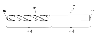
- the drill 1 may have a main body 3 as in the non-limiting example shown in FIGS. 1 to 4.
- the main body 3 may extend from the first end 3a toward the second end 3b along the rotation axis O1.
- the main body 3 may have a rod shape extending from the first end 3a to the second end 3b along the rotation axis O1.
- the first end 3a is called the "tip” and the second end 3b is called the "rear end”.
- the main body 3 can rotate around the rotation axis O1.
- the arrow Y1 in FIG. 1 and the like indicates the rotation direction of the rotation axis O1.
- the main body 3 may have a shank portion 5 and a cutting portion 7.
- the shank portion 5 can be gripped by the rotating spindle of the machine tool.
- the shank portion 5 may be designed according to the shape of the spindle in the machine tool.
- the cutting portion 7 may be located on the side of the first end 3a with respect to the shank portion 5.
- the cutting portion 7 can come into contact with the work material and can play a major role in the cutting process (for example, drilling process) of the work material.
- the outer diameter D of the cutting portion 7 is not limited to a specific value.
- the maximum value of the outer diameter D may be set to 2 to 50 mm.
- the main body 3 may have an outer peripheral surface 9, a cutting edge 11, a flank 13 and a groove 15, as in the case of the unrestricted example shown in FIG.
- the cutting edge 11 may be located on the side of the first end 3a.
- the flank 13 may be located along the cutting edge 11 on the rear side of the rotation axis O1 in the rotation direction Y1.
- the groove 15 may extend from the cutting edge 11 toward the second end 3b.
- the outer peripheral surface 9, the cutting edge 11, the flank 13 and the groove 15 may be located at the cutting portion 7.
- the cutting edge 11 can be used for cutting the work material in the cutting process.
- the cutting blade 11 may have a first blade 17, a second blade 19, and a third blade 21.
- the first blade 17, the second blade 19, and the third blade 21 are also referred to as a main cutting blade.
- the second blade 19 may extend from the first blade 17 toward the outer peripheral surface 9.
- the third blade 21 may extend from the second blade 19 toward the outer peripheral surface 9.
- the first blade 17 may be separated from the rotation shaft O1.
- the second blade 19 may be inclined with respect to the first blade 17 when viewed from a direction orthogonal to the rotation axis O1 and may be a third blade.
- the blade 21 may be tilted with respect to the second blade 19.
- the third blade 21 may be connected to the outer peripheral surface 9.
- the number of the first blades 17 may be one or a plurality. When the number of the first blades 17 is plural, the number may be 2 to 5. These points are the same for the second blade 19 and the third blade 21. As in the non-limiting example shown in FIG. 2, the drill 1 may be a so-called two-flute type drill.
- the plurality of first blades 17 may be positioned so as to be rotationally symmetric with respect to the rotation axis O1 in the front view from the side of the first end 3a.
- the two first blades 17 are the rotation axes in the front view from the side of the first end 3a. It may be positioned so as to be rotationally symmetric with respect to O1. In this case, the straightness of the drill 1 when cutting the work material is high.
- the first blade 17 may have a linear shape or a curved shape when viewed from the side of the first end 3a, or may have a shape in which a linear shape and a curved shape are combined. These points are the same for the second blade 19 and the third blade 21.
- the shapes of the first blade 17, the second blade 19, and the third blade 21 may be the same or different when viewed from the side of the first end 3a.
- the first blade 17 may have a concave curved shape in a front view from the side of the first end 3a.
- the second blade 19 may have a linear shape.
- the third blade 21 may have a convex curved shape.
- the lengths of the first blade 17, the second blade 19, and the third blade 21 may be the same or different.
- the length of the second blade 19 may be longer than the length of the first blade 17.
- the length of the third blade 21 may be longer than the length of the second blade 19.
- the third blade 21 may be the longest in the cutting blade 11.
- the groove 15 can be used to discharge the chips generated by the cutting edge 11 to the outside.
- the groove 15 may extend parallel to the axis of rotation O1 or may extend spirally around the axis of rotation O1.
- the number of grooves 15 may be one or may be plural.
- the groove 15 may be connected to the cutting edge 11. In this case, the bite to the work material is high. Further, a rake surface connecting the groove 15 and the cutting edge 11 may be located. In this case, the discharge direction of the chips generated by the cutting edge 11 is likely to be stable. From the viewpoint of smoothly discharging chips to the outside, the groove 15 may have a concave curved shape in a cross section orthogonal to the rotation axis O1.
- the depth of the groove 15 is not limited to a specific value.
- the depth of the groove 15 may be set to 10 to 40% with respect to the outer diameter of the main body 3 (cutting portion 7).
- the depth of the groove 15 may be a value obtained by subtracting the distance between the bottom of the groove 15 and the rotation axis O1 from the radius of the main body 3 (cutting portion 7) in the cross section orthogonal to the rotation axis O1.
- the bottom may be the portion of the groove 15 closest to the rotation axis O1.
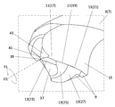
- the flank 13 may have a first flank 23, a second flank 25, and a third flank 27.
- the first flank 23 may be located along the first blade 17.
- the second flank 25 may be located along the second blade 19.
- the third flank 27 may be located along the third blade 21.
- the first flank 23 may be connected to the first blade 17 or may be separated from the first blade 17.
- the second flank 25 may be connected to the second blade 19 or may be separated from the second blade 19.
- the third flank 27 may be connected to the third blade 21 or may be separated from the third blade 21.
- the first flank 23 may be connected to the first blade 17, and the second flank 25 may be connected to the second blade 19.
- the 3 flank 27 may be connected to the 3rd blade 21.
- the flank 13 may have a "sleep angle".
- the "clearance angle” may be defined as follows. First, a cross section orthogonal to the cutting edge 11 may be shown at a target portion of the cutting edge 11. For example, as in the case of the non-limiting example shown in FIGS. 6 to 9, a cross section orthogonal to each of the first blade 17, the second blade 19, and the third blade 21 may be shown.
- the drill 1 When the drill 1 is a so-called two-blade type drill, it may have two portions such as the first blade 17.
- "a" is added to the code indicating one part and "b" is added to the code indicating the other part in FIGS. 6 to 9. .
- one first blade 17 is indicated by reference numeral 17a
- the other first blade 17 is indicated by reference numeral 17b.
- a virtual straight line passing through the cutting edge 11 and in contact with the rotation locus of the cutting edge 11 may be used as the reference line L1.
- the virtual straight line tangent to the rotation locus of this end may be set as the reference line L1.
- the virtual straight line in contact with the end portion of the flank 13 on the side of the cutting edge 11 may be the evaluation line L2. Then, the angle at which the reference line L1 and the evaluation line L2 intersect may be set as a “clearance angle”.
- the first flank 23 may have a first flank angle ⁇ 1 as in the unrestricted example shown in FIG.
- the second flank 25 may have a second flank angle ⁇ 2, as in the unrestricted example shown in FIG.
- the third flank 27 may have a third flank angle ⁇ 3, as in the unrestricted example shown in FIG.
- the second clearance angle ⁇ 2 may be smaller than the first clearance angle ⁇ 1 and the third clearance angle ⁇ 3.
- the first clearance angle ⁇ 1 is relatively large, the cutting edge of the first blade 17 relatively close to the rotation axis O1 can be sharpened, so that the cutting resistance tends to be small and the straight running stability of the drill 1 is high.
- the third clearance angle ⁇ 3 is relatively large, the cutting edge of the third blade 21 which is relatively close to the outer peripheral surface 9 can be sharpened, so that burrs are less likely to occur in the machined hole.
- the second clearance angle ⁇ 2 is relatively small, it is easy to control the movement of the drill 1 in the direction along the rotation axis O1.
- the thrust resistance changes abruptly at the moment of penetrating the work material, it is difficult to control the movement of the drill 1 in the direction along the rotation axis O1.
- the second clearance angle ⁇ 2 is relatively small, the second clearance surface 25 easily comes into contact with the work material, so that it is easy to control the movement of the drill 1 in the direction along the rotation axis O1. Therefore, when the second clearance angle ⁇ 2 is smaller than the first clearance angle ⁇ 1 and the third clearance angle ⁇ 3, the accuracy of the machined hole is high.
- the first clearance angle ⁇ 1 may be the same as or different from the third clearance angle ⁇ 3.
- the thrust resistance is efficiently increased at the tip portion where the depth of cut per rotation is large. It tends to be small. Therefore, for example, straight-line stability is high even for a work material having a large cutting resistance.
- the third clearance surface 27 located on the outer peripheral side is machined as compared with the first clearance surface 23 located near the rotation axis O1. Hard to come in contact with the material. That is, even if the flanks come into contact with the work material, the first flank 23 located closer to the rotation axis O1 is more likely to come into contact with the work material as compared with the third flank 27. Therefore, even when chatter vibration occurs due to the flank contacting the work material, it is easy to suppress the chatter vibration to a small extent.
- the first clearance angle ⁇ 1, the second clearance angle ⁇ 2, and the third clearance angle ⁇ 3 are not limited to specific values.
- the first clearance angle ⁇ 1 may be set to 5 to 15 °.
- the second clearance angle ⁇ 2 may be set to 5 ° or less.
- the third clearance angle ⁇ 3 may be set to 5 to 20 °.
- the first flank 23 may be a flat surface, and the second flank 25 and the third flank 27 may be curved, respectively. In this case, the movement of the drill 1 is easily controlled.
- the tip angle of the drill 1 is easily suppressed to a small value, so that the drill 1 easily bites into the work material.
- the drill 1 tends to swing.
- the second flank 25 and the third flank 27 are curved surfaces, the second flank 25 and the third flank 27 come into contact with the work material when the drill 1 penetrates the work material. Easy to do. Therefore, the runout of the drill 1 is suppressed, and it is easy to maintain the straight running stability.
- the plane may be a plane in general, and does not have to be a plane in a strict sense. This point is the same for curved surfaces.
- the second flank 25 and the third flank 27 may each have a convex curved surface.
- the boundary between the first flank 23 and the second flank 25 may be the first boundary 29.
- the first boundary 29 may approach the outer peripheral surface 9 from the cutting blade 11 (first blade 17 and second blade 19) toward the rear in the rotation direction Y1. In this case, it is easy to suppress chatter vibration caused by the flank contacting the work material. This is because even if the flanks come into contact with the work material, the first flank 23 located closer to the rotation axis O1 is more likely to come into contact with the work material than the second flank 25. Is. As a result, it is easy to suppress chatter vibration while ensuring the length of the second blade 19.
- the first boundary 29 may have a curved shape.
- the boundary between the second flank 25 and the third flank 27 may be the second boundary 31.
- the second boundary 31 may be separated from the outer peripheral surface 9 from the cutting blade 11 (the second blade 19 and the third blade 21) toward the rear in the rotation direction Y1.
- the second boundary 31 may have a curved shape.
- the radius of curvature at the second boundary 31 of the curved shape may be smaller than the radius of curvature at the first boundary 29 of the curved shape.
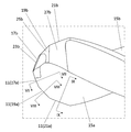
- the second flank 25 has a first region 33 in which the width W in the radial direction of the rotation axis O1 becomes narrower toward the rear of the rotation direction Y1 and a first region 33. It may have a second region 35 which is located behind the rotation direction Y1 and whose width W becomes wider toward the rear of the rotation direction Y1. In this case, when the second flank 25 comes into contact with the work material, the influence of heat generated in the first region 33 can be minimized, and the movement of the drill 1 can be effectively controlled. Will be.
- the second area 35 may be connected to the first area 33.
- the maximum value of the width W in the first region 33 may be the same as or different from the maximum value of the width W in the second region 35.
- the maximum value of the width W in the first region 33 is larger than the maximum value of the width W in the second region 35, heat generation in the second region 35 is suppressed. easy. This is because even if the second flank 25 comes into contact with the work material when the drill 1 penetrates the work material, it is possible to prevent the second region 35 from excessively contacting the work material.
- the second flank 25 may be connected to the first flank 23.
- the third flank 27 may be connected to the second flank 25 or may be connected to the outer peripheral surface 9.
- the areas of the first flank 23, the second flank 25, and the third flank 27 may be the same or different.
- the area of the second flank 25 may be larger than the area of the first flank 23.
- the area of the third flank 27 may be larger than the area of the second flank 25.
- the area of the third flank 27 may be the largest on the flank 13.
- the flank 13 may further have a fourth flank 37 that is located behind the rotation direction Y1 along the first flank 23 and is inclined with respect to the first flank 23.
- the fourth flank 37 may also be referred to as the third flank.
- the fourth flank 37 may be connected to the first flank 23 or may be connected to the second flank 25.
- the fourth flank 37 may be flat.
- the inclination angle of the fourth flank 37 is not limited to a specific value.
- the inclination angle of the fourth flank 37 may be set to 15 to 35 °.
- the cutting edge 11 may have a chisel edge 39.
- the chisel edge 39 can serve to bite into the work material.
- the chisel edge 39 may be located closest to the rotation axis O1 on the cutting edge 11. Further, the chisel edge 39 may intersect with the rotation axis O1.
- the chisel edge 39 may be located between the two first flanks 23.
- the chisel edge 39 may be located at the intersection of the two first flanks 23.
- the chisel edge 39 may be the shortest in the cutting edge 11.
- the chisel edge 39 may have a linear shape when viewed from the side of the first end 3a.
- the cutting edge 11 may have a thinning edge 41.
- the thinning edge 41 may be located closer to the rotation axis O1 than the first blade 17. Further, the thinning edge 41 may be located between the first blade 17 and the chisel edge 39. The thinning edge 41 may be connected to the first blade 17 or may be connected to the chisel edge 39. The length of the thinning edge 41 may be shorter than the length of the first blade 17.
- the thinning edge 41 may have a linear shape when viewed from the side of the first end 3a.
- the main body 3 may have a gash 43 located between the thinning edge 41 and the groove 15.
- the gash 43 may be located along the thinning edge 41 on the front side in the rotation direction Y1.
- Examples of the material of the main body 3 include cemented carbide and cermet.
- Examples of the composition of the cemented carbide include WC-Co, WC-TiC-Co and WC-TiC-TaC-Co.
- WC, TiC and TaC may be hard particles, and Co may be a bonded phase.
- the cermet may be a sintered composite material in which a metal is composited with a ceramic component.
- examples of the cermet may be a titanium compound containing titanium carbide (TiC) or titanium nitride (TiN) as a main component.
- TiC titanium carbide
- TiN titanium nitride
- the above materials are not limited to these materials, and the main body 3 is not limited to these materials.
- the surface of the main body 3 may be coated with a coating using a chemical vapor deposition (CVD) method or a physical vapor deposition (PVD) method.
- CVD chemical vapor deposition
- PVD physical vapor deposition
- the composition of the coating include titanium carbide (TiC), titanium nitride (TiN), titanium carbonitride (TiCN), alumina (Al 2 O 3 ) and the like.
- the machined object 101 may be manufactured by cutting the work material 103.
- the method for manufacturing the machined product 101 may include the following steps (1) to (4).
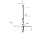
- a step of arranging the drill 1 above the prepared work material 103 (see FIG. 10).
- a step of rotating the drill 1 in the direction of the arrow Y1 around the rotation axis O1 and bringing the drill 1 closer to the work material 103 in the Y2 direction (see FIG. 10).
- the work material 103 may be fixed on the table of the machine tool to which the drill 1 is attached, and the work material 103 may be brought close to the work material 103 while the drill 1 is rotated. good.
- the work material 103 and the drill 1 may be relatively close to each other, and for example, the work material 103 may be brought close to the drill 1.
- cutting may be performed so that at least a part of the cutting portion 7 in the main body 3 is located in the machined hole 105. Further, in the step (3), the shank portion 5 in the main body 3 may be set to be located outside the machined hole 105. From the viewpoint of obtaining a good finished surface, a part of the cutting portion 7 on the side of the second end 3b may be set to be located outside the machined hole 105. It is possible to make a part of the above function as a margin region for chip discharge, and it is possible to exhibit excellent chip discharge property through the region.
- a step of separating the drill 1 from the work material 103 in the Y3 direction (see FIG. 12).
- the work material 103 and the drill 1 may be relatively separated from each other, and for example, the work material 103 may be separated from the drill 1.
- the state in which the drill 1 is rotated is maintained. While doing so, the step of bringing the cutting edge 11 of the drill 1 into contact with different parts of the work material 103 may be repeated.
- Examples of the material of the work material 103 include aluminum, carbon steel, alloy steel, stainless steel, cast iron, and non-ferrous metal.
- Drill 3 Main body 3a ... First end (tip) 3b ... 2nd end (rear end) 5 ... Shank part 7 ... Cutting part 9 ... Outer peripheral surface 11 ... Cutting blade 13 ... Escape surface 15 ... Groove 17 ... 1st blade 19 ... 2nd blade 21 ... 3rd blade 23 ... 1st flank 25 ... 2nd flank 27 ... 3rd flank 29 ... 1st boundary 31 ... 2nd boundary 33 ... 1st Area 35 ... 2nd area 37 ... 4th flank 39 ... Chisel edge 41 ... Thinning edge 43 ... Gash 101 ... Machined work 103 ... Work material 105 ...
Abstract
A drill according to a non-limiting aspect of the present disclosure has a body that extends from a first end to a second end along a rotary axis. The body has: an outer circumferential surface; a cutting edge that is located on the first end side; a flank that is located along the cutting edge on the rearward side in a rotation direction about the rotary axis; and a groove that extends from the cutting edge toward the second end. The cutting edge has: a first blade; a second blade that extends from the first blade toward the outer circumferential surface; and a third blade that extends from the second blade toward the outer circumferential surface. The flank has: a first flank that is located along the first blade and has a first relief angle; a second flank that is located along the second blade and has a second relief angle; and a third flank that is located along the third blade and has a third relief angle. The second relief angle is less than the first relief angle and the third relief angle.
Description
本出願は、2020年5月11日に出願された日本国特許出願2020-082959号の優先権を主張するものであり、この先の出願の開示全体を、ここに参照のために取り込む。
This application claims the priority of Japanese Patent Application No. 2020-082959 filed on May 11, 2020, and the entire disclosure of future applications is incorporated herein by reference.
本開示は、一般的には、被削材の穴あけ加工に用いられるドリル及び切削加工物の製造方法に関する。ドリルとしては、例えば、先端交換式ドリル及びソリッドドリルが挙げられ得る。
The present disclosure generally relates to a method for manufacturing a drill and a machined material used for drilling a work material. Examples of the drill may include a tip exchange type drill and a solid drill.
金属などの被削材を穴あけ加工する際に用いられるドリルとして、例えば特開2010-125592号公報(特許文献1)及び国際公開第2010/086988号(特許文献2)に記載のドリルが知られている。特許文献1に記載のドリルは、切れ刃と、この切れ刃に対して外周側に位置する面取り刃と、を有する。特許文献2に記載のドリルは、第1切れ刃と、この第1切れ刃に対して外周側に位置する第2切れ刃と、を有する。
As a drill used for drilling a work material such as metal, for example, the drills described in Japanese Patent Application Laid-Open No. 2010-125592 (Patent Document 1) and International Publication No. 2010/0868988 (Patent Document 2) are known. ing. The drill described in Patent Document 1 has a cutting edge and a chamfering edge located on the outer peripheral side with respect to the cutting edge. The drill described in Patent Document 2 has a first cutting edge and a second cutting edge located on the outer peripheral side with respect to the first cutting edge.
ドリルを用いて穴あけ加工を行う際に、加工穴の精度を高めることが求められる。
When drilling with a drill, it is required to improve the accuracy of the drilled hole.
本開示の限定されない一面に基づくドリルは、回転軸に沿って第1端から第2端に向かって延びた本体を有する。前記本体は、外周面と、前記第1端の側に位置する切刃と、前記回転軸の回転方向の後方側において前記切刃に沿って位置する逃げ面と、前記切刃から前記第2端に向かって延びた溝と、を有する。前記切刃は、第1刃と、前記第1刃から前記外周面に向かって延びた第2刃と、前記第2刃から前記外周面に向かって延びた第3刃と、を有する。前記逃げ面は、前記第1刃に沿って位置し、第1逃げ角を有する第1逃げ面と、前記第2刃に沿って位置し、第2逃げ角を有する第2逃げ面と、前記第3刃に沿って位置し、第3逃げ角を有する第3逃げ面と、を有する。前記第2逃げ角は、前記第1逃げ角及び前記第3逃げ角よりも小さい。
The unrestricted one-sided drill of the present disclosure has a body extending from the first end to the second end along the axis of rotation. The main body has an outer peripheral surface, a cutting edge located on the side of the first end, a flank located along the cutting edge on the rear side in the rotation direction of the rotating shaft, and the second from the cutting edge. It has a groove extending towards the edge. The cutting blade has a first blade, a second blade extending from the first blade toward the outer peripheral surface, and a third blade extending from the second blade toward the outer peripheral surface. The flanks are a first flank located along the first blade and having a first flank angle, a second flank located along the second blade and having a second flank angle, and the above. It has a third flank, which is located along the third blade and has a third flank angle. The second clearance angle is smaller than the first clearance angle and the third clearance angle.
<ドリル>
以下、本開示の限定されない一面のドリル1について、図面を用いて詳細に説明する。但し、以下で参照する各図では、説明の便宜上、実施形態を説明する上で必要な主要部材のみが簡略化して示される。したがって、ドリル1は、参照する各図に示されない任意の構成部材を備え得る。また、各図中の部材の寸法は、実際の構成部材の寸法及び各部材の寸法比率などを忠実に表したものではない。 <Drill>
Hereinafter, the one-sided drill 1 without limitation of the present disclosure will be described in detail with reference to the drawings. However, in each of the figures referred to below, for convenience of explanation, only the main members necessary for explaining the embodiment are shown in a simplified manner. Therefore, the drill 1 may include any component not shown in each referenced figure. Further, the dimensions of the members in each drawing do not faithfully represent the dimensions of the actual constituent members and the dimensional ratio of each member.
以下、本開示の限定されない一面のドリル1について、図面を用いて詳細に説明する。但し、以下で参照する各図では、説明の便宜上、実施形態を説明する上で必要な主要部材のみが簡略化して示される。したがって、ドリル1は、参照する各図に示されない任意の構成部材を備え得る。また、各図中の部材の寸法は、実際の構成部材の寸法及び各部材の寸法比率などを忠実に表したものではない。 <Drill>
Hereinafter, the one-
なお、限定されない一面においては、ドリル1の一例としてソリッドドリルが示され得る。但し、ドリル1は、ソリッドドリルに限定されず、例えば先端交換式ドリルなどであってもよい。
In one aspect without limitation, a solid drill may be shown as an example of the drill 1. However, the drill 1 is not limited to a solid drill, and may be, for example, a tip exchange type drill.
ドリル1は、図1~図4に示す限定されない一例のように、本体3を有してもよい。本体3は、回転軸O1に沿って第1端3aから第2端3bに向かって延びてもよい。言い換えれば、本体3は、回転軸O1に沿って第1端3aから第2端3bにかけて延びた棒形状であってもよい。一般的には、第1端3aが「先端」と呼ばれ、第2端3bが「後端」と呼ばれる。また、本体3は、回転軸O1の周りで回転可能である。なお、図1などにおける矢印Y1は、回転軸O1の回転方向を示している。
The drill 1 may have a main body 3 as in the non-limiting example shown in FIGS. 1 to 4. The main body 3 may extend from the first end 3a toward the second end 3b along the rotation axis O1. In other words, the main body 3 may have a rod shape extending from the first end 3a to the second end 3b along the rotation axis O1. Generally, the first end 3a is called the "tip" and the second end 3b is called the "rear end". Further, the main body 3 can rotate around the rotation axis O1. The arrow Y1 in FIG. 1 and the like indicates the rotation direction of the rotation axis O1.
本体3は、シャンク部5及び切削部7を有してもよい。シャンク部5は、工作機械の回転するスピンドルに把持されることが可能である。シャンク部5は、工作機械におけるスピンドルの形状に応じて設計されてもよい。
The main body 3 may have a shank portion 5 and a cutting portion 7. The shank portion 5 can be gripped by the rotating spindle of the machine tool. The shank portion 5 may be designed according to the shape of the spindle in the machine tool.
切削部7は、シャンク部5に対して第1端3aの側に位置してもよい。切削部7は、被削材に接触することが可能であって、被削材の切削加工(例えば、穴あけ加工)において主要な役割を果たすことが可能である。
The cutting portion 7 may be located on the side of the first end 3a with respect to the shank portion 5. The cutting portion 7 can come into contact with the work material and can play a major role in the cutting process (for example, drilling process) of the work material.
切削部7の外径Dは、特定の値に限定されない。例えば、外径Dの最大値は、2~50mmに設定されてもよい。また、回転軸O1に沿った方向における切削部7の長さLは、L=1.5D~12Dに設定されてもよい。
The outer diameter D of the cutting portion 7 is not limited to a specific value. For example, the maximum value of the outer diameter D may be set to 2 to 50 mm. Further, the length L of the cutting portion 7 in the direction along the rotation axis O1 may be set to L = 1.5D to 12D.
本体3は、図5に示す限定されない一例のように、外周面9、切刃11、逃げ面13及び溝15を有してもよい。切刃11は、第1端3aの側に位置してもよい。逃げ面13は、回転軸O1の回転方向Y1の後方側において切刃11に沿って位置してもよい。溝15は、切刃11から第2端3bに向かって延びてもよい。なお、外周面9、切刃11、逃げ面13及び溝15は、切削部7に位置してもよい。
The main body 3 may have an outer peripheral surface 9, a cutting edge 11, a flank 13 and a groove 15, as in the case of the unrestricted example shown in FIG. The cutting edge 11 may be located on the side of the first end 3a. The flank 13 may be located along the cutting edge 11 on the rear side of the rotation axis O1 in the rotation direction Y1. The groove 15 may extend from the cutting edge 11 toward the second end 3b. The outer peripheral surface 9, the cutting edge 11, the flank 13 and the groove 15 may be located at the cutting portion 7.
切刃11は、切削加工において被削材を切削するために用いることが可能である。切刃11は、第1刃17、第2刃19及び第3刃21を有してもよい。第1刃17、第2刃19及び第3刃21は、主切刃とも呼ばれる。第2刃19は、第1刃17から外周面9に向かって延びてもよい。第3刃21は、第2刃19から外周面9に向かって延びてもよい。なお、第1刃17は、回転軸O1から離れてもよい。図3及び図6に示す限定されない一例のように、回転軸O1に直交する方向から見た場合に、第2刃19は、第1刃17に対して傾斜してもよく、また、第3刃21は、第2刃19に対して傾斜してもよい。第3刃21は、外周面9に接続されてもよい。
The cutting edge 11 can be used for cutting the work material in the cutting process. The cutting blade 11 may have a first blade 17, a second blade 19, and a third blade 21. The first blade 17, the second blade 19, and the third blade 21 are also referred to as a main cutting blade. The second blade 19 may extend from the first blade 17 toward the outer peripheral surface 9. The third blade 21 may extend from the second blade 19 toward the outer peripheral surface 9. The first blade 17 may be separated from the rotation shaft O1. As in the non-limiting example shown in FIGS. 3 and 6, the second blade 19 may be inclined with respect to the first blade 17 when viewed from a direction orthogonal to the rotation axis O1 and may be a third blade. The blade 21 may be tilted with respect to the second blade 19. The third blade 21 may be connected to the outer peripheral surface 9.
第1刃17の数は、1つであってもよく、また、複数であってもよい。第1刃17の数が複数の場合には、その数は、2~5であってもよい。これらの点は、第2刃19及び第3刃21においても同様である。図2に示す限定されない一例のように、ドリル1は、いわゆる2枚刃型のドリルであってもよい。
The number of the first blades 17 may be one or a plurality. When the number of the first blades 17 is plural, the number may be 2 to 5. These points are the same for the second blade 19 and the third blade 21. As in the non-limiting example shown in FIG. 2, the drill 1 may be a so-called two-flute type drill.
第1刃17の数が複数の場合には、第1端3aの側からの正面視において、複数の第1刃17が回転軸O1に対して回転対称となるように位置してもよい。具体的には、図2に示す限定されない一例のように、第1刃17の数が2つの場合には、第1端3aの側からの正面視において、2つの第1刃17が回転軸O1に対して180°の回転対称となるように位置してもよい。この場合には、被削材を切削する際のドリル1の直進性が高い。これらの点は、第2刃19及び第3刃21においても同様である。
When the number of the first blades 17 is plural, the plurality of first blades 17 may be positioned so as to be rotationally symmetric with respect to the rotation axis O1 in the front view from the side of the first end 3a. Specifically, as in the case of the unrestricted example shown in FIG. 2, when the number of the first blades 17 is two, the two first blades 17 are the rotation axes in the front view from the side of the first end 3a. It may be positioned so as to be rotationally symmetric with respect to O1. In this case, the straightness of the drill 1 when cutting the work material is high. These points are the same for the second blade 19 and the third blade 21.
第1刃17は、第1端3aの側からの正面視において、直線形状又は曲線形状であってもよく、直線形状と曲線形状とが組み合わされた形状であってもよい。これらの点は、第2刃19及び第3刃21においても同様である。
The first blade 17 may have a linear shape or a curved shape when viewed from the side of the first end 3a, or may have a shape in which a linear shape and a curved shape are combined. These points are the same for the second blade 19 and the third blade 21.
第1端3aの側からの正面視において、第1刃17、第2刃19及び第3刃21のそれぞれの形状は、同じであってもよく、また、異なってもよい。例えば、図2に示す限定されない一例のように、第1端3aの側からの正面視において、第1刃17は、凹曲線形状であってもよい。また、第2刃19は、直線形状であってもよい。第3刃21は、凸曲線形状であってもよい。
The shapes of the first blade 17, the second blade 19, and the third blade 21 may be the same or different when viewed from the side of the first end 3a. For example, as in the unrestricted example shown in FIG. 2, the first blade 17 may have a concave curved shape in a front view from the side of the first end 3a. Further, the second blade 19 may have a linear shape. The third blade 21 may have a convex curved shape.
第1刃17、第2刃19及び第3刃21のそれぞれの長さは、同じであってもよく、また、異なってもよい。例えば、図2に示す限定されない一例のように、第2刃19の長さは、第1刃17の長さよりも長くてもよい。また、第3刃21の長さは、第2刃19の長さよりも長くてもよい。第3刃21は、切刃11において最も長くてもよい。
The lengths of the first blade 17, the second blade 19, and the third blade 21 may be the same or different. For example, as in the unrestricted example shown in FIG. 2, the length of the second blade 19 may be longer than the length of the first blade 17. Further, the length of the third blade 21 may be longer than the length of the second blade 19. The third blade 21 may be the longest in the cutting blade 11.
溝15は、切刃11で生じた切屑を外部に排出するために用いることが可能である。溝15は、回転軸O1に平行に延びてもよく、また、回転軸O1の周りで螺旋状に延びてもよい。溝15の数は、1つであってもよく、また、複数であってもよい。
The groove 15 can be used to discharge the chips generated by the cutting edge 11 to the outside. The groove 15 may extend parallel to the axis of rotation O1 or may extend spirally around the axis of rotation O1. The number of grooves 15 may be one or may be plural.
溝15は、切刃11に接続されてもよい。この場合には、被削材に対する食い付き性が高い。また、溝15と切刃11との間に両者を接続するすくい面が位置してもよい。この場合には、切刃11で生じた切屑の排出方向が安定し易い。切屑を円滑に外部に排出するという観点から、回転軸O1に直交する断面において、溝15は凹曲線形状であってもよい。
The groove 15 may be connected to the cutting edge 11. In this case, the bite to the work material is high. Further, a rake surface connecting the groove 15 and the cutting edge 11 may be located. In this case, the discharge direction of the chips generated by the cutting edge 11 is likely to be stable. From the viewpoint of smoothly discharging chips to the outside, the groove 15 may have a concave curved shape in a cross section orthogonal to the rotation axis O1.
溝15の深さは、特定の値に限定されない。例えば、本体3(切削部7)の外径に対し、溝15の深さは、10~40%に設定されてもよい。溝15の深さとは、回転軸O1に直交する断面において、溝15の底と回転軸O1との距離を本体3(切削部7)の半径から引いた値のことであってもよい。底とは、溝15における回転軸O1に最も近い部分のことであってもよい。
The depth of the groove 15 is not limited to a specific value. For example, the depth of the groove 15 may be set to 10 to 40% with respect to the outer diameter of the main body 3 (cutting portion 7). The depth of the groove 15 may be a value obtained by subtracting the distance between the bottom of the groove 15 and the rotation axis O1 from the radius of the main body 3 (cutting portion 7) in the cross section orthogonal to the rotation axis O1. The bottom may be the portion of the groove 15 closest to the rotation axis O1.
逃げ面13は、第1逃げ面23、第2逃げ面25及び第3逃げ面27を有してもよい。第1逃げ面23は、第1刃17に沿って位置してもよい。第2逃げ面25は、第2刃19に沿って位置してもよい。第3逃げ面27は、第3刃21に沿って位置してもよい。
The flank 13 may have a first flank 23, a second flank 25, and a third flank 27. The first flank 23 may be located along the first blade 17. The second flank 25 may be located along the second blade 19. The third flank 27 may be located along the third blade 21.
なお、第1逃げ面23は、第1刃17に接続されてもよく、また、第1刃17から離れてもよい。同様に、第2逃げ面25は、第2刃19に接続されてもよく、また、第2刃19から離れてもよい。第3逃げ面27は、第3刃21に接続されてもよく、また、第3刃21から離れてもよい。例えば、図2に示す限定されない一例のように、第1逃げ面23は、第1刃17に接続されてもよく、第2逃げ面25は、第2刃19に接続されてもよく、第3逃げ面27は、第3刃21に接続されてもよい。
The first flank 23 may be connected to the first blade 17 or may be separated from the first blade 17. Similarly, the second flank 25 may be connected to the second blade 19 or may be separated from the second blade 19. The third flank 27 may be connected to the third blade 21 or may be separated from the third blade 21. For example, as in the non-limiting example shown in FIG. 2, the first flank 23 may be connected to the first blade 17, and the second flank 25 may be connected to the second blade 19. The 3 flank 27 may be connected to the 3rd blade 21.
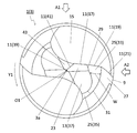
逃げ面13は、「逃げ角」を有してもよい。「逃げ角」は、次のように定義してもよい。まず、切刃11における対象とする部分において、切刃11に直交する断面を示してもよい。例えば、図6~図9に示す限定されない一例のように、第1刃17、第2刃19及び第3刃21のそれぞれに直交する断面を示してもよい。なお、ドリル1が、いわゆる2枚刃型のドリルである場合には、第1刃17などの部位を2つずつ有してもよい。各部位の位置関係における視覚的な理解を容易にするため、図6~図9において、一方の部位を示す符号に「a」、もう一方の部位を示す符号に「b」を付している。例えば、図6及び図7において、一方の第1刃17を符号17a、もう一方の第1刃17を符号17bで示している。
The flank 13 may have a "sleep angle". The "clearance angle" may be defined as follows. First, a cross section orthogonal to the cutting edge 11 may be shown at a target portion of the cutting edge 11. For example, as in the case of the non-limiting example shown in FIGS. 6 to 9, a cross section orthogonal to each of the first blade 17, the second blade 19, and the third blade 21 may be shown. When the drill 1 is a so-called two-blade type drill, it may have two portions such as the first blade 17. In order to facilitate a visual understanding of the positional relationship of each part, "a" is added to the code indicating one part and "b" is added to the code indicating the other part in FIGS. 6 to 9. .. For example, in FIGS. 6 and 7, one first blade 17 is indicated by reference numeral 17a, and the other first blade 17 is indicated by reference numeral 17b.
上記の断面において、切刃11を通り、且つ、切刃11の回転軌跡に接する仮想直線を基準線L1としてもよい。面取り加工或いはホーニング加工が切刃11に施されており、微視的に見て切刃11が平面或いは凸曲面である場合は、切刃11における逃げ面13の側の端部を通り、且つ、この端部の回転軌跡に接する仮想直線を基準線L1としてもよい。逃げ面13における切刃11の側の端部に接する仮想直線を評価線L2としてもよい。そして、基準線L1及び評価線L2の交わる角度を「逃げ角」としてもよい。
In the above cross section, a virtual straight line passing through the cutting edge 11 and in contact with the rotation locus of the cutting edge 11 may be used as the reference line L1. When chamfering or honing is applied to the cutting edge 11 and the cutting edge 11 is microscopically a flat surface or a convex curved surface, it passes through the end portion of the cutting edge 11 on the side of the flank 13 and , The virtual straight line tangent to the rotation locus of this end may be set as the reference line L1. The virtual straight line in contact with the end portion of the flank 13 on the side of the cutting edge 11 may be the evaluation line L2. Then, the angle at which the reference line L1 and the evaluation line L2 intersect may be set as a “clearance angle”.
第1逃げ面23は、図7に示す限定されない一例のように、第1逃げ角θ1を有してもよい。第2逃げ面25は、図8に示す限定されない一例のように、第2逃げ角θ2を有してもよい。第3逃げ面27は、図9に示す限定されない一例のように、第3逃げ角θ3を有してもよい。
The first flank 23 may have a first flank angle θ1 as in the unrestricted example shown in FIG. The second flank 25 may have a second flank angle θ2, as in the unrestricted example shown in FIG. The third flank 27 may have a third flank angle θ3, as in the unrestricted example shown in FIG.
ここで、第2逃げ角θ2は、第1逃げ角θ1及び第3逃げ角θ3よりも小さくてもよい。第1逃げ角θ1が相対的に大きい場合には、回転軸O1に相対的に近い第1刃17の刃先を鋭くできるため、切削抵抗が小さくなり易く、ドリル1の直進安定性が高い。また、第3逃げ角θ3が相対的に大きい場合には、外周面9に相対的に近い第3刃21の刃先を鋭くできるため、加工穴にバリが生じにくい。そして、第2逃げ角θ2が相対的に小さい場合には、回転軸O1に沿った方向におけるドリル1の動きを制御し易い。すなわち、被削材を貫通した瞬間にスラスト抵抗が急激に変化するため、回転軸O1に沿った方向におけるドリル1の動きの制御が難しい。しかし、第2逃げ角θ2が相対的に小さい場合には、第2逃げ面25が被削材に接触し易いため、回転軸O1に沿った方向におけるドリル1の動きの制御が容易である。そのため、第2逃げ角θ2が、第1逃げ角θ1及び第3逃げ角θ3よりも小さい場合には、加工穴の精度が高い。
Here, the second clearance angle θ2 may be smaller than the first clearance angle θ1 and the third clearance angle θ3. When the first clearance angle θ1 is relatively large, the cutting edge of the first blade 17 relatively close to the rotation axis O1 can be sharpened, so that the cutting resistance tends to be small and the straight running stability of the drill 1 is high. Further, when the third clearance angle θ3 is relatively large, the cutting edge of the third blade 21 which is relatively close to the outer peripheral surface 9 can be sharpened, so that burrs are less likely to occur in the machined hole. When the second clearance angle θ2 is relatively small, it is easy to control the movement of the drill 1 in the direction along the rotation axis O1. That is, since the thrust resistance changes abruptly at the moment of penetrating the work material, it is difficult to control the movement of the drill 1 in the direction along the rotation axis O1. However, when the second clearance angle θ2 is relatively small, the second clearance surface 25 easily comes into contact with the work material, so that it is easy to control the movement of the drill 1 in the direction along the rotation axis O1. Therefore, when the second clearance angle θ2 is smaller than the first clearance angle θ1 and the third clearance angle θ3, the accuracy of the machined hole is high.
第1逃げ角θ1は、第3逃げ角θ3と同じであってもよく、また、異なってもよい。図7及び図9に示す限定されない一例のように、第1逃げ角θ1が、第3逃げ角θ3よりも大きい場合には、1回転当たりの切り込み量が大きい先端部分で効率的にスラスト抵抗が小さくなり易い。そのため、例えば切削抵抗が大きい被削材に対しても直進安定性が高い。
The first clearance angle θ1 may be the same as or different from the third clearance angle θ3. As in the unrestricted example shown in FIGS. 7 and 9, when the first clearance angle θ1 is larger than the third clearance angle θ3, the thrust resistance is efficiently increased at the tip portion where the depth of cut per rotation is large. It tends to be small. Therefore, for example, straight-line stability is high even for a work material having a large cutting resistance.
第1逃げ角θ1が、第3逃げ角θ3よりも小さい場合には、外周側に位置する第3逃げ面27が、回転軸O1の近くに位置する第1逃げ面23と比較して被削材に接触しにくい。すなわち、仮に逃げ面が被削材に接触する場合であっても第3逃げ面27と比較して、回転軸O1の近くに位置する第1逃げ面23が被削材に接触し易い。そのため、逃げ面が被削材に接触することに起因するびびり振動が生じる場合であっても、このびびり振動を小さく抑制し易い。
When the first clearance angle θ1 is smaller than the third clearance angle θ3, the third clearance surface 27 located on the outer peripheral side is machined as compared with the first clearance surface 23 located near the rotation axis O1. Hard to come in contact with the material. That is, even if the flanks come into contact with the work material, the first flank 23 located closer to the rotation axis O1 is more likely to come into contact with the work material as compared with the third flank 27. Therefore, even when chatter vibration occurs due to the flank contacting the work material, it is easy to suppress the chatter vibration to a small extent.
第1逃げ角θ1、第2逃げ角θ2及び第3逃げ角θ3は、特定の値に限定されない。例えば、第1逃げ角θ1は、5~15°に設定されてもよい。また、第2逃げ角θ2は、5°以下に設定されてもよい。第3逃げ角θ3は、5~20°に設定されてもよい。
The first clearance angle θ1, the second clearance angle θ2, and the third clearance angle θ3 are not limited to specific values. For example, the first clearance angle θ1 may be set to 5 to 15 °. Further, the second clearance angle θ2 may be set to 5 ° or less. The third clearance angle θ3 may be set to 5 to 20 °.
第1逃げ面23が平面であって、且つ、第2逃げ面25及び第3逃げ面27がそれぞれ曲面であってもよい。この場合には、ドリル1の動きが制御され易い。第1逃げ面23が平面である場合には、ドリル1の先端角が小さい値に抑えられ易いため、被削材にドリル1が食い付き易い。加えて、例えば切削加工時においてドリル1が被削材を貫通する際にドリル1が振れ易い。しかしながら、第2逃げ面25及び第3逃げ面27が曲面である場合には、ドリル1が被削材を貫通する際に、第2逃げ面25及び第3逃げ面27が被削材と接触し易い。そのため、ドリル1の振れが抑えられ、直進安定性を保ち易い。
The first flank 23 may be a flat surface, and the second flank 25 and the third flank 27 may be curved, respectively. In this case, the movement of the drill 1 is easily controlled. When the first flank 23 is a flat surface, the tip angle of the drill 1 is easily suppressed to a small value, so that the drill 1 easily bites into the work material. In addition, for example, when the drill 1 penetrates the work material during cutting, the drill 1 tends to swing. However, when the second flank 25 and the third flank 27 are curved surfaces, the second flank 25 and the third flank 27 come into contact with the work material when the drill 1 penetrates the work material. Easy to do. Therefore, the runout of the drill 1 is suppressed, and it is easy to maintain the straight running stability.
なお、平面とは、概ね平面であればよく、厳密な意味での平面である必要はない。この点は、曲面においても同様である。第2逃げ面25及び第3逃げ面27は、それぞれ凸曲面であってもよい。
Note that the plane may be a plane in general, and does not have to be a plane in a strict sense. This point is the same for curved surfaces. The second flank 25 and the third flank 27 may each have a convex curved surface.
図2に示す限定されない一例のように、第1逃げ面23及び第2逃げ面25の境界を第1境界29としてもよい。この第1境界29は、切刃11(第1刃17及び第2刃19)から回転方向Y1の後方に向かうにしたがって外周面9に近づいてもよい。この場合には、逃げ面が被削材に接触することに起因するびびり振動を小さく抑制し易い。これは、仮に逃げ面が被削材に接触する場合であっても第2逃げ面25と比較して、回転軸O1の近くに位置する第1逃げ面23が被削材に接触し易いためである。これにより、第2刃19の長さを確保しつつ、びびり振動を小さく抑制し易い。なお、第1境界29は、曲線形状であってもよい。
As an example without limitation shown in FIG. 2, the boundary between the first flank 23 and the second flank 25 may be the first boundary 29. The first boundary 29 may approach the outer peripheral surface 9 from the cutting blade 11 (first blade 17 and second blade 19) toward the rear in the rotation direction Y1. In this case, it is easy to suppress chatter vibration caused by the flank contacting the work material. This is because even if the flanks come into contact with the work material, the first flank 23 located closer to the rotation axis O1 is more likely to come into contact with the work material than the second flank 25. Is. As a result, it is easy to suppress chatter vibration while ensuring the length of the second blade 19. The first boundary 29 may have a curved shape.
第2逃げ面25及び第3逃げ面27の境界を第2境界31としてもよい。この第2境界31は、切刃11(第2刃19及び第3刃21)から回転方向Y1の後方に向かうにしたがって外周面9から離れてもよい。なお、第2境界31は、曲線形状であってもよい。曲線形状の第2境界31における曲率半径は、曲線形状の第1境界29における曲率半径よりも小さくてもよい。
The boundary between the second flank 25 and the third flank 27 may be the second boundary 31. The second boundary 31 may be separated from the outer peripheral surface 9 from the cutting blade 11 (the second blade 19 and the third blade 21) toward the rear in the rotation direction Y1. The second boundary 31 may have a curved shape. The radius of curvature at the second boundary 31 of the curved shape may be smaller than the radius of curvature at the first boundary 29 of the curved shape.
第1端3aの側からの正面視において、第2逃げ面25は、回転方向Y1の後方に向かうにしたがって回転軸O1の径方向における幅Wが狭くなる第1領域33と、第1領域33よりも回転方向Y1の後方に位置し、回転方向Y1の後方に向かうにしたがって幅Wが広くなる第2領域35と、を有してもよい。この場合には、第2逃げ面25が被削材に接触した際に、第1領域33において発生する熱の影響を最小限に抑え、ドリル1の動きの制御を効果的に行うことが可能となる。なお、第2領域35は、第1領域33に接続されてもよい。
In the front view from the side of the first end 3a, the second flank 25 has a first region 33 in which the width W in the radial direction of the rotation axis O1 becomes narrower toward the rear of the rotation direction Y1 and a first region 33. It may have a second region 35 which is located behind the rotation direction Y1 and whose width W becomes wider toward the rear of the rotation direction Y1. In this case, when the second flank 25 comes into contact with the work material, the influence of heat generated in the first region 33 can be minimized, and the movement of the drill 1 can be effectively controlled. Will be. The second area 35 may be connected to the first area 33.
第1領域33における幅Wの最大値は、第2領域35における幅Wの最大値と同じであってもよく、また、異なってもよい。図2に示す限定されない一例のように、第1領域33における幅Wの最大値が、第2領域35における幅Wの最大値よりも大きい場合には、第2領域35における熱の発生を抑え易い。ドリル1が被削材を貫通する際に第2逃げ面25が被削材に接触したとしても、第2領域35が被削材に過剰に接触することが避けられるためである。
The maximum value of the width W in the first region 33 may be the same as or different from the maximum value of the width W in the second region 35. As in the unrestricted example shown in FIG. 2, when the maximum value of the width W in the first region 33 is larger than the maximum value of the width W in the second region 35, heat generation in the second region 35 is suppressed. easy. This is because even if the second flank 25 comes into contact with the work material when the drill 1 penetrates the work material, it is possible to prevent the second region 35 from excessively contacting the work material.
なお、第2逃げ面25は、第1逃げ面23に接続されてもよい。第3逃げ面27は、第2逃げ面25に接続されてもよく、また、外周面9に接続されてもよい。
The second flank 25 may be connected to the first flank 23. The third flank 27 may be connected to the second flank 25 or may be connected to the outer peripheral surface 9.
第1逃げ面23、第2逃げ面25及び第3逃げ面27のそれぞれの面積は、同じであってもよく、また、異なってもよい。例えば、図2に示す限定されない一例のように、第2逃げ面25の面積は、第1逃げ面23の面積よりも大きくてもよい。また、第3逃げ面27の面積は、第2逃げ面25の面積よりも大きくてもよい。第3逃げ面27の面積は、逃げ面13において最も大きくてもよい。
The areas of the first flank 23, the second flank 25, and the third flank 27 may be the same or different. For example, as in the unrestricted example shown in FIG. 2, the area of the second flank 25 may be larger than the area of the first flank 23. Further, the area of the third flank 27 may be larger than the area of the second flank 25. The area of the third flank 27 may be the largest on the flank 13.
逃げ面13は、回転方向Y1の後方において第1逃げ面23に沿って位置し、且つ、第1逃げ面23に対して傾斜した第4逃げ面37をさらに有してもよい。第4逃げ面37は、3番逃げ面とも呼ばれ得る。
The flank 13 may further have a fourth flank 37 that is located behind the rotation direction Y1 along the first flank 23 and is inclined with respect to the first flank 23. The fourth flank 37 may also be referred to as the third flank.
第4逃げ面37は、第1逃げ面23に接続されてもよく、また、第2逃げ面25に接続されてもよい。第4逃げ面37は、平面であってもよい。第4逃げ面37の傾斜角度は、特定の値に限定されない。例えば、第4逃げ面37の傾斜角度は、15~35°に設定されてもよい。
The fourth flank 37 may be connected to the first flank 23 or may be connected to the second flank 25. The fourth flank 37 may be flat. The inclination angle of the fourth flank 37 is not limited to a specific value. For example, the inclination angle of the fourth flank 37 may be set to 15 to 35 °.
切刃11は、チゼルエッジ39を有してもよい。チゼルエッジ39は、被削材に食い付く役割を果たすことが可能である。チゼルエッジ39は、切刃11において最も回転軸O1の近くに位置してもよい。また、チゼルエッジ39は、回転軸O1と交差してもよい。チゼルエッジ39は、2つの第1逃げ面23の間に位置してもよい。チゼルエッジ39は、2つの第1逃げ面23の交わりに位置してもよい。チゼルエッジ39は、切刃11において最も短くてもよい。チゼルエッジ39は、第1端3aの側からの正面視において、直線形状であってもよい。
The cutting edge 11 may have a chisel edge 39. The chisel edge 39 can serve to bite into the work material. The chisel edge 39 may be located closest to the rotation axis O1 on the cutting edge 11. Further, the chisel edge 39 may intersect with the rotation axis O1. The chisel edge 39 may be located between the two first flanks 23. The chisel edge 39 may be located at the intersection of the two first flanks 23. The chisel edge 39 may be the shortest in the cutting edge 11. The chisel edge 39 may have a linear shape when viewed from the side of the first end 3a.
切刃11は、シンニングエッジ41を有してもよい。シンニングエッジ41は、第1刃17よりも回転軸O1の側に位置してもよい。また、シンニングエッジ41は、第1刃17及びチゼルエッジ39の間に位置してもよい。シンニングエッジ41は、第1刃17に接続されてもよく、また、チゼルエッジ39に接続されてもよい。シンニングエッジ41の長さは、第1刃17の長さよりも短くてもよい。シンニングエッジ41は、第1端3aの側からの正面視において、直線形状であってもよい。
The cutting edge 11 may have a thinning edge 41. The thinning edge 41 may be located closer to the rotation axis O1 than the first blade 17. Further, the thinning edge 41 may be located between the first blade 17 and the chisel edge 39. The thinning edge 41 may be connected to the first blade 17 or may be connected to the chisel edge 39. The length of the thinning edge 41 may be shorter than the length of the first blade 17. The thinning edge 41 may have a linear shape when viewed from the side of the first end 3a.
本体3は、シンニングエッジ41及び溝15の間に位置するギャッシュ43を有してもよい。ギャッシュ43は、回転方向Y1の前方側においてシンニングエッジ41に沿って位置してもよい。
The main body 3 may have a gash 43 located between the thinning edge 41 and the groove 15. The gash 43 may be located along the thinning edge 41 on the front side in the rotation direction Y1.
本体3の材質としては、例えば、超硬合金及びサーメットなどが挙げられ得る。超硬合金の組成としては、例えば、WC-Co、WC-TiC-Co及びWC-TiC-TaC-Coが挙げられ得る。ここで、WC、TiC及びTaCは硬質粒子であってもよく、また、Coは結合相であってもよい。
Examples of the material of the main body 3 include cemented carbide and cermet. Examples of the composition of the cemented carbide include WC-Co, WC-TiC-Co and WC-TiC-TaC-Co. Here, WC, TiC and TaC may be hard particles, and Co may be a bonded phase.
また、サーメットは、セラミック成分に金属を複合させた焼結複合材料であってもよい。具体的には、サーメットとして、炭化チタン(TiC)又は窒化チタン(TiN)を主成分としたチタン化合物が挙げられ得る。但し、上記の材質は限定されない一例であって、本体3は、これらの材質に限定されない。
Further, the cermet may be a sintered composite material in which a metal is composited with a ceramic component. Specifically, examples of the cermet may be a titanium compound containing titanium carbide (TiC) or titanium nitride (TiN) as a main component. However, the above materials are not limited to these materials, and the main body 3 is not limited to these materials.
本体3の表面は、化学蒸着(CVD)法、又は、物理蒸着(PVD)法を用いて被膜でコーティングされてもよい。被膜の組成としては、例えば、炭化チタン(TiC)、窒化チタン(TiN)、炭窒化チタン(TiCN)及びアルミナ(Al2O3)などが挙げられ得る。
The surface of the main body 3 may be coated with a coating using a chemical vapor deposition (CVD) method or a physical vapor deposition (PVD) method. Examples of the composition of the coating include titanium carbide (TiC), titanium nitride (TiN), titanium carbonitride (TiCN), alumina (Al 2 O 3 ) and the like.
<切削加工物の製造方法>
次に、本開示の限定されない一面の切削加工物101の製造方法について図10~図12を用いて説明する。 <Manufacturing method of machined material>
Next, a method of manufacturing the one-sidedmachined product 101, which is not limited to the present disclosure, will be described with reference to FIGS. 10 to 12.
次に、本開示の限定されない一面の切削加工物101の製造方法について図10~図12を用いて説明する。 <Manufacturing method of machined material>
Next, a method of manufacturing the one-sided
切削加工物101は、被削材103を切削加工することによって作製してもよい。切削加工物101の製造方法は、以下の(1)~(4)の工程を有してもよい。
The machined object 101 may be manufactured by cutting the work material 103. The method for manufacturing the machined product 101 may include the following steps (1) to (4).
(1)準備された被削材103に対して上方にドリル1を配置する工程(図10参照)。
(2)回転軸O1を中心に矢印Y1の方向にドリル1を回転させ、被削材103に向かってY2方向にドリル1を近づける工程(図10参照)。 (1) A step of arranging thedrill 1 above the prepared work material 103 (see FIG. 10).
(2) A step of rotating thedrill 1 in the direction of the arrow Y1 around the rotation axis O1 and bringing the drill 1 closer to the work material 103 in the Y2 direction (see FIG. 10).
(2)回転軸O1を中心に矢印Y1の方向にドリル1を回転させ、被削材103に向かってY2方向にドリル1を近づける工程(図10参照)。 (1) A step of arranging the
(2) A step of rotating the
(1)及び(2)の工程は、例えば、ドリル1が取り付けられた工作機械のテーブルの上に被削材103を固定し、ドリル1を回転させた状態で被削材103に近づけてもよい。なお、(2)の工程では、被削材103とドリル1とは相対的に近づけばよく、例えば、被削材103をドリル1に近づけてもよい。
In the steps (1) and (2), for example, the work material 103 may be fixed on the table of the machine tool to which the drill 1 is attached, and the work material 103 may be brought close to the work material 103 while the drill 1 is rotated. good. In the step (2), the work material 103 and the drill 1 may be relatively close to each other, and for example, the work material 103 may be brought close to the drill 1.
(3)ドリル1をさらに被削材103に近づけることによって、回転しているドリル1を、被削材103の表面の所望の位置に接触させて、被削材103に加工穴105を形成する工程(図11参照)。
(3) By bringing the drill 1 closer to the work material 103, the rotating drill 1 is brought into contact with a desired position on the surface of the work material 103 to form a machined hole 105 in the work material 103. Step (see FIG. 11).
(3)の工程では、本体3における切削部7の少なくとも一部が加工穴105の中に位置するように切削加工を行ってもよい。また、(3)の工程では、本体3におけるシャンク部5が、加工穴105の外側に位置するように設定してもよい。良好な仕上げ面を得る観点から、切削部7のうち第2端3bの側の一部が加工穴105の外側に位置するように設定してもよい。上記の一部を切屑排出のためのマージン領域として機能させることが可能であり、当該領域を介して優れた切屑排出性を奏することが可能である。
In the step (3), cutting may be performed so that at least a part of the cutting portion 7 in the main body 3 is located in the machined hole 105. Further, in the step (3), the shank portion 5 in the main body 3 may be set to be located outside the machined hole 105. From the viewpoint of obtaining a good finished surface, a part of the cutting portion 7 on the side of the second end 3b may be set to be located outside the machined hole 105. It is possible to make a part of the above function as a margin region for chip discharge, and it is possible to exhibit excellent chip discharge property through the region.
(4)ドリル1を被削材103からY3方向に離す工程(図12参照)。
(4)の工程においても、上記の(2)の工程と同様に、被削材103とドリル1とは相対的に離せばよく、例えば、被削材103をドリル1から離してもよい。 (4) A step of separating thedrill 1 from the work material 103 in the Y3 direction (see FIG. 12).
In the step (4) as well, as in the step (2) above, thework material 103 and the drill 1 may be relatively separated from each other, and for example, the work material 103 may be separated from the drill 1.
(4)の工程においても、上記の(2)の工程と同様に、被削材103とドリル1とは相対的に離せばよく、例えば、被削材103をドリル1から離してもよい。 (4) A step of separating the
In the step (4) as well, as in the step (2) above, the
以上のような工程を経る場合には、精度が高い加工穴105を有する切削加工物101を得ることが可能となる。
When the above steps are performed, it is possible to obtain a machined product 101 having a machined hole 105 with high accuracy.
なお、被削材103の切削加工を複数回行う場合であって、例えば、1つの被削材103に対して複数の加工穴105を形成する場合には、ドリル1を回転させた状態を保持しつつ、被削材103の異なる箇所にドリル1の切刃11を接触させる工程を繰り返してもよい。
When the work material 103 is cut a plurality of times, for example, when a plurality of machined holes 105 are formed in one work material 103, the state in which the drill 1 is rotated is maintained. While doing so, the step of bringing the cutting edge 11 of the drill 1 into contact with different parts of the work material 103 may be repeated.
被削材103の材質としては、例えば、アルミニウム、炭素鋼、合金鋼、ステンレス、鋳鉄及び非鉄金属などが挙げられ得る。
Examples of the material of the work material 103 include aluminum, carbon steel, alloy steel, stainless steel, cast iron, and non-ferrous metal.
1・・・ドリル
3・・・本体
3a・・第1端(先端)
3b・・第2端(後端)
5・・・シャンク部
7・・・切削部
9・・・外周面
11・・・切刃
13・・・逃げ面
15・・・溝
17・・・第1刃
19・・・第2刃
21・・・第3刃
23・・・第1逃げ面
25・・・第2逃げ面
27・・・第3逃げ面
29・・・第1境界
31・・・第2境界
33・・・第1領域
35・・・第2領域
37・・・第4逃げ面
39・・・チゼルエッジ
41・・・シンニングエッジ
43・・・ギャッシュ
101・・・切削加工物
103・・・被削材
105・・・加工穴
O1・・・回転軸
Y1・・・回転方向
L1・・・基準線
L2・・・評価線
θ1・・・第1逃げ角
θ2・・・第2逃げ角
θ3・・・第3逃げ角 1 ...Drill 3 ... Main body 3a ... First end (tip)
3b ... 2nd end (rear end)
5 ...Shank part 7 ... Cutting part 9 ... Outer peripheral surface 11 ... Cutting blade 13 ... Escape surface 15 ... Groove 17 ... 1st blade 19 ... 2nd blade 21 ... 3rd blade 23 ... 1st flank 25 ... 2nd flank 27 ... 3rd flank 29 ... 1st boundary 31 ... 2nd boundary 33 ... 1st Area 35 ... 2nd area 37 ... 4th flank 39 ... Chisel edge 41 ... Thinning edge 43 ... Gash 101 ... Machined work 103 ... Work material 105 ... Machined hole O1 ・ ・ ・ Rotation axis Y1 ・ ・ ・ Rotation direction L1 ・ ・ ・ Reference line L2 ・ ・ ・ Evaluation line θ1 ・ ・ ・ First clearance angle θ2 ・ ・ ・ Second clearance angle θ3 ・ ・ ・ Third clearance angle
3・・・本体
3a・・第1端(先端)
3b・・第2端(後端)
5・・・シャンク部
7・・・切削部
9・・・外周面
11・・・切刃
13・・・逃げ面
15・・・溝
17・・・第1刃
19・・・第2刃
21・・・第3刃
23・・・第1逃げ面
25・・・第2逃げ面
27・・・第3逃げ面
29・・・第1境界
31・・・第2境界
33・・・第1領域
35・・・第2領域
37・・・第4逃げ面
39・・・チゼルエッジ
41・・・シンニングエッジ
43・・・ギャッシュ
101・・・切削加工物
103・・・被削材
105・・・加工穴
O1・・・回転軸
Y1・・・回転方向
L1・・・基準線
L2・・・評価線
θ1・・・第1逃げ角
θ2・・・第2逃げ角
θ3・・・第3逃げ角 1 ...
3b ... 2nd end (rear end)
5 ...
Claims (9)
- 回転軸に沿って第1端から第2端に向かって延びた本体を有し、
前記本体は、
外周面と、
前記第1端の側に位置する切刃と、
前記回転軸の回転方向の後方側において前記切刃に沿って位置する逃げ面と、
前記切刃から前記第2端に向かって延びた溝と、を有し、
前記切刃は、
第1刃と、
前記第1刃から前記外周面に向かって延びた第2刃と、
前記第2刃から前記外周面に向かって延びた第3刃と、を有し、
前記逃げ面は、
前記第1刃に沿って位置し、第1逃げ角を有する第1逃げ面と、
前記第2刃に沿って位置し、第2逃げ角を有する第2逃げ面と、
前記第3刃に沿って位置し、第3逃げ角を有する第3逃げ面と、を有し、
前記第2逃げ角は、前記第1逃げ角及び前記第3逃げ角よりも小さい、ドリル。 It has a body that extends from the first end to the second end along the axis of rotation.
The main body is
The outer peripheral surface and
The cutting edge located on the side of the first end,
A flank located along the cutting edge on the rear side of the rotation axis in the rotation direction,
It has a groove extending from the cutting edge toward the second end.
The cutting edge is
With the first blade
A second blade extending from the first blade toward the outer peripheral surface,
It has a third blade extending from the second blade toward the outer peripheral surface, and has.
The flank is
A first flank surface located along the first blade and having a first flank angle,
A second flank located along the second blade and having a second flank angle,
It has a third flank surface that is located along the third blade and has a third flank angle.
The second clearance angle is smaller than the first clearance angle and the third clearance angle, the drill. - 前記第1逃げ角は、前記第3逃げ角よりも大きい、請求項1に記載のドリル。 The drill according to claim 1, wherein the first clearance angle is larger than the third clearance angle.
- 前記第1逃げ角は、前記第3逃げ角よりも小さい、請求項1に記載のドリル。 The drill according to claim 1, wherein the first clearance angle is smaller than the third clearance angle.
- 前記第1逃げ面は、平面であって、且つ、前記第2逃げ面及び前記第3逃げ面は、それぞれ曲面である、請求項1~3のいずれか1つに記載のドリル。 The drill according to any one of claims 1 to 3, wherein the first flank surface is a flat surface, and the second flank surface and the third flank surface are curved surfaces, respectively.
- 前記第1逃げ面及び前記第2逃げ面の第1境界は、前記切刃から前記回転方向の後方に向かうにしたがって前記外周面に近づく、請求項1~4のいずれか1つに記載のドリル。 The drill according to any one of claims 1 to 4, wherein the first flank and the first boundary of the second flank approach the outer peripheral surface from the cutting edge toward the rear in the rotational direction. ..
- 前記第2逃げ面及び前記第3逃げ面の第2境界は、前記切刃から前記回転方向の後方に向かうにしたがって前記外周面から離れる、請求項1~5のいずれか1つに記載のドリル。 The drill according to any one of claims 1 to 5, wherein the second flank and the second boundary of the third flank depart from the outer peripheral surface toward the rear in the rotational direction from the cutting edge. ..
- 前記第1端の側からの正面視において、前記第2逃げ面は、
前記回転方向の後方に向かうにしたがって前記回転軸の径方向における幅が狭くなる第1領域と、
前記第1領域よりも前記回転方向の後方に位置し、前記回転方向の後方に向かうにしたがって前記径方向における幅が広くなる第2領域と、を有する、請求項1~6のいずれか1つに記載のドリル。 In front view from the side of the first end, the second flank is
A first region in which the width of the rotation axis in the radial direction becomes narrower toward the rear in the rotation direction, and
One of claims 1 to 6, wherein the second region is located behind the first region in the rotation direction and becomes wider in the radial direction toward the rear of the rotation direction. The drill described in. - 前記第1領域における前記径方向の幅の最大値が、前記第2領域における前記径方向の幅の最大値よりも大きい、請求項7に記載のドリル。 The drill according to claim 7, wherein the maximum value of the radial width in the first region is larger than the maximum value of the radial width in the second region.
- 請求項1~8のいずれか1つに記載のドリルを回転させる工程と、
回転している前記ドリルを被削材に接触させる工程と、
前記ドリルを前記被削材から離す工程と、を有する切削加工物の製造方法。 The step of rotating the drill according to any one of claims 1 to 8,
The process of bringing the rotating drill into contact with the work material,
A method for manufacturing a machined product, comprising a step of separating the drill from the work material.
Priority Applications (4)
| Application Number | Priority Date | Filing Date | Title |
|---|---|---|---|
| JP2022521889A JP7386339B2 (en) | 2020-05-11 | 2021-05-10 | Manufacturing method for drills and cutting products |
| DE112021002713.1T DE112021002713T5 (en) | 2020-05-11 | 2021-05-10 | DRILLS AND METHOD OF MAKING A MACHINED PRODUCT |
| CN202180032930.3A CN115515740A (en) | 2020-05-11 | 2021-05-10 | Drill and method for manufacturing cut product |
| US17/998,041 US20230173594A1 (en) | 2020-05-11 | 2021-05-10 | Drill and method for manufacturing machined product |
Applications Claiming Priority (2)
| Application Number | Priority Date | Filing Date | Title |
|---|---|---|---|
| JP2020-082959 | 2020-05-11 | ||
| JP2020082959 | 2020-05-11 |
Publications (1)
| Publication Number | Publication Date |
|---|---|
| WO2021230176A1 true WO2021230176A1 (en) | 2021-11-18 |
Family
ID=78525800
Family Applications (1)
| Application Number | Title | Priority Date | Filing Date |
|---|---|---|---|
| PCT/JP2021/017620 WO2021230176A1 (en) | 2020-05-11 | 2021-05-10 | Drill and method for manufacturing cut workpiece |
Country Status (5)
| Country | Link |
|---|---|
| US (1) | US20230173594A1 (en) |
| JP (1) | JP7386339B2 (en) |
| CN (1) | CN115515740A (en) |
| DE (1) | DE112021002713T5 (en) |
| WO (1) | WO2021230176A1 (en) |
Citations (5)
| Publication number | Priority date | Publication date | Assignee | Title |
|---|---|---|---|---|
| US20100135741A1 (en) * | 2008-12-03 | 2010-06-03 | Black & Decker Inc. | Drill Bit Including One Piece Cutting Head |
| JP2010155289A (en) * | 2008-12-26 | 2010-07-15 | Fuji Heavy Ind Ltd | Drill |
| WO2014069453A1 (en) * | 2012-10-29 | 2014-05-08 | 京セラ株式会社 | Ball end mill |
| US20170066062A1 (en) * | 2015-09-08 | 2017-03-09 | Mitsubishi Materials Corporation | Drill |
| WO2019039001A1 (en) * | 2017-08-22 | 2019-02-28 | 住友電工ハードメタル株式会社 | Rotary cutting tool and manufacturing method thereof |
Family Cites Families (2)
| Publication number | Priority date | Publication date | Assignee | Title |
|---|---|---|---|---|
| WO2010086988A1 (en) | 2009-01-29 | 2010-08-05 | オーエスジー株式会社 | Double angle drill |
| JP7139910B2 (en) | 2018-11-21 | 2022-09-21 | トヨタ自動車株式会社 | power train system |
-
2021
- 2021-05-10 WO PCT/JP2021/017620 patent/WO2021230176A1/en active Application Filing
- 2021-05-10 US US17/998,041 patent/US20230173594A1/en active Pending
- 2021-05-10 CN CN202180032930.3A patent/CN115515740A/en active Pending
- 2021-05-10 JP JP2022521889A patent/JP7386339B2/en active Active
- 2021-05-10 DE DE112021002713.1T patent/DE112021002713T5/en active Pending
Patent Citations (5)
| Publication number | Priority date | Publication date | Assignee | Title |
|---|---|---|---|---|
| US20100135741A1 (en) * | 2008-12-03 | 2010-06-03 | Black & Decker Inc. | Drill Bit Including One Piece Cutting Head |
| JP2010155289A (en) * | 2008-12-26 | 2010-07-15 | Fuji Heavy Ind Ltd | Drill |
| WO2014069453A1 (en) * | 2012-10-29 | 2014-05-08 | 京セラ株式会社 | Ball end mill |
| US20170066062A1 (en) * | 2015-09-08 | 2017-03-09 | Mitsubishi Materials Corporation | Drill |
| WO2019039001A1 (en) * | 2017-08-22 | 2019-02-28 | 住友電工ハードメタル株式会社 | Rotary cutting tool and manufacturing method thereof |
Also Published As
| Publication number | Publication date |
|---|---|
| JP7386339B2 (en) | 2023-11-24 |
| JPWO2021230176A1 (en) | 2021-11-18 |
| CN115515740A (en) | 2022-12-23 |
| DE112021002713T5 (en) | 2023-02-23 |
| US20230173594A1 (en) | 2023-06-08 |
Similar Documents
| Publication | Publication Date | Title |
|---|---|---|
| JP6892503B2 (en) | Rotating tool | |
| JP7168673B2 (en) | Manufacturing method for cutting insert, rotating tool and cutting work | |
| JP7055865B2 (en) | Manufacturing method for rotary tools and cuttings | |
| US11351617B2 (en) | Rotating tool | |
| WO2018180775A1 (en) | Rotating tool | |
| JP7103933B2 (en) | Manufacturing method for cutting inserts, rotary tools and machined products | |
| JP7142681B2 (en) | Manufacturing method for drills and cutting products | |
| JP6882517B2 (en) | Rotating tool | |
| JP7417707B2 (en) | End mill and method for manufacturing cut products | |
| WO2021230176A1 (en) | Drill and method for manufacturing cut workpiece | |
| JPWO2019088013A1 (en) | Manufacturing method for drills and cut products | |
| JP6941047B2 (en) | Manufacturing method for rotary tools and cuttings | |
| WO2021153599A1 (en) | Rotating tool and method for manufacturing cut workpieces | |
| WO2019139075A1 (en) | Drill and method for producing cut article | |
| JP7279163B2 (en) | Manufacturing method for rotary tool and cut product | |
| WO2021020259A1 (en) | Drill and method for manufacturing cut workpiece | |
| WO2021117822A1 (en) | Drill and method for manufacturing cut workpiece | |
| CN114072249B (en) | Rotary tool and method for manufacturing cut product | |
| JP7465980B2 (en) | Method for manufacturing rotary tools and machined products | |
| WO2023181814A1 (en) | Drill, and method for manufacturing cut workpiece | |
| JP2024021376A (en) | Manufacturing method for drills and cutting products | |
| JP2020069558A (en) | Rotary tool and manufacturing method for cutting work-piece | |
| JP2021100772A (en) | Rotary tool and cut product manufacturing method | |
| JP2019217616A (en) | Rotary tool and method for manufacturing work-piece to be cut | |
| JP2001341024A (en) | Drill for cutting stainless steel |
Legal Events
| Date | Code | Title | Description |
|---|---|---|---|
| 121 | Ep: the epo has been informed by wipo that ep was designated in this application |
Ref document number: 21803551 Country of ref document: EP Kind code of ref document: A1 |
|
| ENP | Entry into the national phase |
Ref document number: 2022521889 Country of ref document: JP Kind code of ref document: A |
|
| 122 | Ep: pct application non-entry in european phase |
Ref document number: 21803551 Country of ref document: EP Kind code of ref document: A1 |