WO2021229852A1 - 振動装置 - Google Patents
振動装置 Download PDFInfo
- Publication number
- WO2021229852A1 WO2021229852A1 PCT/JP2020/048772 JP2020048772W WO2021229852A1 WO 2021229852 A1 WO2021229852 A1 WO 2021229852A1 JP 2020048772 W JP2020048772 W JP 2020048772W WO 2021229852 A1 WO2021229852 A1 WO 2021229852A1
- Authority
- WO
- WIPO (PCT)
- Prior art keywords
- adhesive layer
- thickness
- tubular body
- body cover
- vibration
- Prior art date
Links
- 239000012790 adhesive layer Substances 0.000 claims abstract description 200
- 125000006850 spacer group Chemical group 0.000 claims description 25
- 238000006073 displacement reaction Methods 0.000 abstract description 38
- XLYOFNOQVPJJNP-UHFFFAOYSA-N water Substances O XLYOFNOQVPJJNP-UHFFFAOYSA-N 0.000 abstract description 15
- 230000005540 biological transmission Effects 0.000 abstract description 4
- 230000035882 stress Effects 0.000 description 34
- 238000003384 imaging method Methods 0.000 description 11
- 239000002184 metal Substances 0.000 description 10
- 229910052751 metal Inorganic materials 0.000 description 10
- 229920005989 resin Polymers 0.000 description 10
- 239000011347 resin Substances 0.000 description 10
- 239000010410 layer Substances 0.000 description 9
- 239000000463 material Substances 0.000 description 8
- 238000001514 detection method Methods 0.000 description 7
- 239000000919 ceramic Substances 0.000 description 6
- 238000010586 diagram Methods 0.000 description 6
- 230000008646 thermal stress Effects 0.000 description 6
- 230000000694 effects Effects 0.000 description 5
- 239000011521 glass Substances 0.000 description 5
- 230000003287 optical effect Effects 0.000 description 5
- HFGPZNIAWCZYJU-UHFFFAOYSA-N lead zirconate titanate Chemical compound [O-2].[O-2].[O-2].[O-2].[O-2].[Ti+4].[Zr+4].[Pb+2] HFGPZNIAWCZYJU-UHFFFAOYSA-N 0.000 description 4
- 229910052451 lead zirconate titanate Inorganic materials 0.000 description 4
- 230000002093 peripheral effect Effects 0.000 description 4
- 239000004925 Acrylic resin Substances 0.000 description 2
- 229920000178 Acrylic resin Polymers 0.000 description 2
- CDBYLPFSWZWCQE-UHFFFAOYSA-L Sodium Carbonate Chemical compound [Na+].[Na+].[O-]C([O-])=O CDBYLPFSWZWCQE-UHFFFAOYSA-L 0.000 description 2
- 239000000853 adhesive Substances 0.000 description 2
- 230000001070 adhesive effect Effects 0.000 description 2
- -1 and for example Substances 0.000 description 2
- 238000013016 damping Methods 0.000 description 2
- 230000005674 electromagnetic induction Effects 0.000 description 2
- 239000003822 epoxy resin Substances 0.000 description 2
- 229920000647 polyepoxide Polymers 0.000 description 2
- 230000035945 sensitivity Effects 0.000 description 2
- 229920002050 silicone resin Polymers 0.000 description 2
- 229910001220 stainless steel Inorganic materials 0.000 description 2
- 239000010935 stainless steel Substances 0.000 description 2
- 239000000758 substrate Substances 0.000 description 2
- 229910013641 LiNbO 3 Inorganic materials 0.000 description 1
- 238000010521 absorption reaction Methods 0.000 description 1
- 239000013078 crystal Substances 0.000 description 1
- NKZSPGSOXYXWQA-UHFFFAOYSA-N dioxido(oxo)titanium;lead(2+) Chemical compound [Pb+2].[O-][Ti]([O-])=O NKZSPGSOXYXWQA-UHFFFAOYSA-N 0.000 description 1
- 229920006332 epoxy adhesive Polymers 0.000 description 1
- 229910052737 gold Inorganic materials 0.000 description 1
- 239000012212 insulator Substances 0.000 description 1
- 230000007246 mechanism Effects 0.000 description 1
- 238000000034 method Methods 0.000 description 1
- 238000012806 monitoring device Methods 0.000 description 1
- 239000004033 plastic Substances 0.000 description 1
- 230000000644 propagated effect Effects 0.000 description 1
- 239000010453 quartz Substances 0.000 description 1
- 230000029058 respiratory gaseous exchange Effects 0.000 description 1
- VYPSYNLAJGMNEJ-UHFFFAOYSA-N silicon dioxide Inorganic materials O=[Si]=O VYPSYNLAJGMNEJ-UHFFFAOYSA-N 0.000 description 1
- 229910052709 silver Inorganic materials 0.000 description 1
- HUAUNKAZQWMVFY-UHFFFAOYSA-M sodium;oxocalcium;hydroxide Chemical compound [OH-].[Na+].[Ca]=O HUAUNKAZQWMVFY-UHFFFAOYSA-M 0.000 description 1
- 238000004544 sputter deposition Methods 0.000 description 1
- 238000006467 substitution reaction Methods 0.000 description 1
- 239000010409 thin film Substances 0.000 description 1
Images


Classifications
-
- H—ELECTRICITY
- H10—SEMICONDUCTOR DEVICES; ELECTRIC SOLID-STATE DEVICES NOT OTHERWISE PROVIDED FOR
- H10N—ELECTRIC SOLID-STATE DEVICES NOT OTHERWISE PROVIDED FOR
- H10N30/00—Piezoelectric or electrostrictive devices
- H10N30/20—Piezoelectric or electrostrictive devices with electrical input and mechanical output, e.g. functioning as actuators or vibrators
-
- B—PERFORMING OPERATIONS; TRANSPORTING
- B06—GENERATING OR TRANSMITTING MECHANICAL VIBRATIONS IN GENERAL
- B06B—METHODS OR APPARATUS FOR GENERATING OR TRANSMITTING MECHANICAL VIBRATIONS OF INFRASONIC, SONIC, OR ULTRASONIC FREQUENCY, e.g. FOR PERFORMING MECHANICAL WORK IN GENERAL
- B06B1/00—Methods or apparatus for generating mechanical vibrations of infrasonic, sonic, or ultrasonic frequency
- B06B1/02—Methods or apparatus for generating mechanical vibrations of infrasonic, sonic, or ultrasonic frequency making use of electrical energy
- B06B1/06—Methods or apparatus for generating mechanical vibrations of infrasonic, sonic, or ultrasonic frequency making use of electrical energy operating with piezoelectric effect or with electrostriction
-
- B—PERFORMING OPERATIONS; TRANSPORTING
- B08—CLEANING
- B08B—CLEANING IN GENERAL; PREVENTION OF FOULING IN GENERAL
- B08B7/00—Cleaning by methods not provided for in a single other subclass or a single group in this subclass
- B08B7/02—Cleaning by methods not provided for in a single other subclass or a single group in this subclass by distortion, beating, or vibration of the surface to be cleaned
-
- G—PHYSICS
- G02—OPTICS
- G02B—OPTICAL ELEMENTS, SYSTEMS OR APPARATUS
- G02B27/00—Optical systems or apparatus not provided for by any of the groups G02B1/00 - G02B26/00, G02B30/00
- G02B27/0006—Optical systems or apparatus not provided for by any of the groups G02B1/00 - G02B26/00, G02B30/00 with means to keep optical surfaces clean, e.g. by preventing or removing dirt, stains, contamination, condensation
-
- G—PHYSICS
- G02—OPTICS
- G02B—OPTICAL ELEMENTS, SYSTEMS OR APPARATUS
- G02B7/00—Mountings, adjusting means, or light-tight connections, for optical elements
- G02B7/02—Mountings, adjusting means, or light-tight connections, for optical elements for lenses
-
- G—PHYSICS
- G03—PHOTOGRAPHY; CINEMATOGRAPHY; ANALOGOUS TECHNIQUES USING WAVES OTHER THAN OPTICAL WAVES; ELECTROGRAPHY; HOLOGRAPHY
- G03B—APPARATUS OR ARRANGEMENTS FOR TAKING PHOTOGRAPHS OR FOR PROJECTING OR VIEWING THEM; APPARATUS OR ARRANGEMENTS EMPLOYING ANALOGOUS TECHNIQUES USING WAVES OTHER THAN OPTICAL WAVES; ACCESSORIES THEREFOR
- G03B17/00—Details of cameras or camera bodies; Accessories therefor
- G03B17/02—Bodies
- G03B17/08—Waterproof bodies or housings
-
- H—ELECTRICITY
- H02—GENERATION; CONVERSION OR DISTRIBUTION OF ELECTRIC POWER
- H02K—DYNAMO-ELECTRIC MACHINES
- H02K5/00—Casings; Enclosures; Supports
-
- H—ELECTRICITY
- H10—SEMICONDUCTOR DEVICES; ELECTRIC SOLID-STATE DEVICES NOT OTHERWISE PROVIDED FOR
- H10N—ELECTRIC SOLID-STATE DEVICES NOT OTHERWISE PROVIDED FOR
- H10N30/00—Piezoelectric or electrostrictive devices
- H10N30/704—Piezoelectric or electrostrictive devices based on piezoelectric or electrostrictive films or coatings
- H10N30/706—Piezoelectric or electrostrictive devices based on piezoelectric or electrostrictive films or coatings characterised by the underlying bases, e.g. substrates
- H10N30/708—Intermediate layers, e.g. barrier, adhesion or growth control buffer layers
-
- H—ELECTRICITY
- H10—SEMICONDUCTOR DEVICES; ELECTRIC SOLID-STATE DEVICES NOT OTHERWISE PROVIDED FOR
- H10N—ELECTRIC SOLID-STATE DEVICES NOT OTHERWISE PROVIDED FOR
- H10N30/00—Piezoelectric or electrostrictive devices
- H10N30/80—Constructional details
- H10N30/87—Electrodes or interconnections, e.g. leads or terminals
-
- H—ELECTRICITY
- H10—SEMICONDUCTOR DEVICES; ELECTRIC SOLID-STATE DEVICES NOT OTHERWISE PROVIDED FOR
- H10N—ELECTRIC SOLID-STATE DEVICES NOT OTHERWISE PROVIDED FOR
- H10N30/00—Piezoelectric or electrostrictive devices
- H10N30/01—Manufacture or treatment
- H10N30/07—Forming of piezoelectric or electrostrictive parts or bodies on an electrical element or another base
- H10N30/072—Forming of piezoelectric or electrostrictive parts or bodies on an electrical element or another base by laminating or bonding of piezoelectric or electrostrictive bodies
- H10N30/073—Forming of piezoelectric or electrostrictive parts or bodies on an electrical element or another base by laminating or bonding of piezoelectric or electrostrictive bodies by fusion of metals or by adhesives
Definitions
- the present invention relates to a vibration device capable of removing water droplets or the like by mechanical vibration.
- Patent Document 1 discloses an example of a vibrating device.
- a piezoelectric element is attached to the lens cover via a connector.
- a housing is attached to the piezoelectric element via an insulator.
- the light sensor is built in the housing. The piezoelectric element vibrates the lens cover in order to remove the droplets adhering to the lens cover.
- Patent Document 1 describes that when a metal is used for a connector, an epoxy adhesive is used for joining the connector and the piezoelectric element. In this case, if the difference in the coefficient of linear expansion between the metal used for the connector and the piezoelectric element is large, the thermal stress increases. Therefore, the piezoelectric element may be peeled off from the connector, or the piezoelectric element may be cracked. On the other hand, the adhesive used to join the lens cover and the connector may dampen the vibration.
- An object of the present invention is to provide a vibration device capable of reducing the stress applied to each member without reducing the displacement of the translucent body cover to which water droplets or the like adhere.
- the vibrating device is a vibrating element having an opening and being bonded to a tubular body having a first opening end surface and a second opening end surface and the first opening end surface of the tubular body. And a translucent body cover bonded to the second opening end surface of the tubular body so as to cover the opening of the tubular body, and the tubular body and the vibrating element are the first.
- the tubular body and the translucent body cover are joined by a second adhesive layer, and the thickness of the first adhesive layer is t1 and the second is the second.
- the thickness of the adhesive layer is t2, and the absolute value of the amount of deformation in the thickness direction when a constant stress is applied to the first adhesive layer in the thickness direction of the first adhesive layer
- the absolute value of the amount of deformation in the thickness direction when a constant stress is applied to the second adhesive layer in the thickness direction of the second adhesive layer is
- , and the first adhesive is used.
- when the same stress is applied to the layer and the second adhesive layer is
- the vibrating device it is possible to reduce the stress applied to each member without reducing the displacement of the translucent body cover to which water droplets or the like adhere.
- FIG. 1 is a front sectional view of the vibration device according to the first embodiment of the present invention.
- FIG. 2 is an exploded perspective view of the vibration device according to the first embodiment of the present invention.
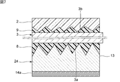
- FIG. 3 is an enlarged front sectional view showing the vicinity of the first adhesive layer and the second adhesive layer of the vibration device according to the first embodiment of the present invention.
- FIG. 4 is a diagram showing the relationship between the maximum displacement amount of the translucent body cover of the present invention and the thickness of the adhesive layer.
- FIG. 5 shows the relationship between the maximum shear stress applied between the tubular body and the piezoelectric element and the maximum shear stress applied between the tubular body and the translucent body cover at low temperature, and the thickness of the adhesive layer. It is a figure.
- FIG. 1 is a front sectional view of the vibration device according to the first embodiment of the present invention.
- FIG. 2 is an exploded perspective view of the vibration device according to the first embodiment of the present invention.
- FIG. 3 is an enlarged front sectional view showing the vicinity of the
- FIG. 6 is a diagram showing the relationship between the maximum displacement amount of the translucent body cover and the Young's modulus of the adhesive layer.
- FIG. 7 is an enlarged front sectional view showing the vicinity of the first adhesive layer and the second adhesive layer of the vibration device according to the third embodiment of the present invention.
- FIG. 8 is a front sectional view of the vibration device according to the fourth embodiment of the present invention.
- FIG. 9 is an enlarged front sectional view showing the vicinity of the first adhesive layer and the second adhesive layer of the vibration device according to the fifth embodiment of the present invention.
- FIG. 10 is a diagram showing the relationship between the vibration amplitude of the translucent body cover and the thickness of the second adhesive layer.
- FIG. 11 is a perspective view of the imaging device according to the fifth embodiment of the present invention.
- FIG. 12 is a cross-sectional view taken along the line I-I in FIG.
- FIG. 1 is a front sectional view of the vibration device according to the first embodiment of the present invention.
- FIG. 2 is an exploded perspective view of the vibration device according to the first embodiment.
- the vibrating device 1 shown in FIGS. 1 and 2 is a vibrating device that removes water droplets and foreign matter from the field of view of the image pickup element by moving water droplets and foreign matter by vibration or atomizing the water droplets.
- the vibrating device 1 has a translucent body cover 2, a tubular body 3, a piezoelectric element 4, and a holding member 6. Further, as shown in FIG. 1, the vibrating device 1 has a first adhesive layer 8 and a second adhesive layer 9.
- the tubular body 3 and the piezoelectric element 4 are joined by a first adhesive layer 8.
- the tubular body 3 and the translucent body cover 2 are joined by a second adhesive layer 9.
- the internal space is composed of the translucent body cover 2, the tubular body 3, and the holding member 6.
- An optical detection element such as an image pickup device is arranged in this internal space.
- the internal space is not limited to a closed space, and a space partially open to the outside is also referred to as an internal space.
- the tubular body 3 has an opening 3e and has a first opening end surface 3a and a second opening end surface 3b.
- the direction connecting the first opening end surface 3a and the second opening end surface 3b of the tubular body 3 is defined as the axial direction Z
- the direction orthogonal to the axial direction Z is defined as the radial direction.
- the tubular body 3 extends in the axial direction Z.
- the tubular body 3 has an inner side surface 3c and an outer side surface 3d. The inner side surface 3c and the outer side surface 3d are connected to the first opening end surface 3a and the second opening end surface 3b.
- the first opening end face 3a is flat.
- a wall portion 3f is provided on the second opening end surface 3b.
- the wall portion 3f has an annular shape.
- the wall portion 3f is located between the outer peripheral edge and the inner peripheral edge of the tubular body 3 in a plan view.
- the portion of the second opening end surface 3b that is radially inner side of the wall portion 3f is flat.
- the wall portion 3f may not be provided.
- the plan view means a direction viewed from above the axial direction Z.
- the upper part in the axial direction Z corresponds to the upper part in FIG.
- the tubular body 3 has a substantially cylindrical shape.
- the shape of the tubular body 3 is not limited to a substantially cylindrical shape, and may be, for example, a substantially square tubular shape.
- the tubular body 3 is made of an appropriate metal.
- the material of the tubular body 3 is not limited to metal, and for example, ceramics and the like can be used.
- the piezoelectric element 4 is bonded to the first open end surface 3a of the tubular body 3. More specifically, the first open end surface 3a and the piezoelectric element 4 are bonded by the first adhesive layer 8. As shown in FIG. 2, the piezoelectric element 4 has an annular shape.
- the piezoelectric element 4 has an annular piezoelectric body 13.
- the piezoelectric body 13 has a first main surface 13a and a second main surface 13b. More specifically, the first main surface 13a and the second main surface 13b face each other in the axial direction Z.
- the second main surface 13b is located on the tubular body 3 side.
- the piezoelectric element 4 has a first electrode 14a and a second electrode 14b.
- the first electrode 14a is provided on the first main surface 13a of the piezoelectric body 13.
- the second electrode 14b is provided on the second main surface 13b.
- the first electrode 14a and the second electrode 14b are provided so as to face each other.
- the shapes of the first electrode 14a and the second electrode 14b are annular, respectively.
- an appropriate metal can be used as the material of the first electrode 14a and the second electrode 14b.
- the first electrode 14a and the second electrode 14b may be electrodes made of, for example, a metal thin film such as Ag or Au. In this case, the first electrode 14a and the second electrode 14b can be formed by a sputtering method or the like.
- Examples of the material of the piezoelectric body 13 include appropriate piezoelectric ceramics such as PZT (lead zirconate titanate), PT (lead titanate) and (K, Na) NbO 3, or appropriate piezoelectric ceramics such as LiTaO 3 and LiNbO 3. A single crystal or the like may be used.
- the shape of the piezoelectric body 13 is not limited to the above.
- the holding member 6 is connected to the first opening end surface 3a of the tubular body 3.
- the holding member 6 has a spring portion 17 and a bottom portion 18.
- One end of the spring portion 17 is connected to the first open end surface 3a of the tubular body 3.
- a bottom portion 18 is connected to the other end of the spring portion 17.
- the cross-sectional shape of the spring portion 17 along the axial direction Z is a stepped shape.
- the shape of the bottom 18 is cylindrical.
- the shapes of the spring portion 17 and the bottom portion 18 are not limited to the above.
- the spring portion 17 may have a shape such as a cylinder or a square cylinder.
- the bottom portion 18 may have a shape such as a square cylinder.
- the holding member 6 is made of an appropriate metal.
- the material of the holding member 6 is not limited to metal, and for example, ceramic or the like can be used.
- the vibrating device 1 is fixed to the outside, for example, at the bottom 18 of the holding member 6.
- the holding member 6 is connected to the tubular body 3.
- the tubular body 3 and the holding member 6 may be integrated.
- the tubular body 3 includes a portion corresponding to the holding member 6.
- a translucent body cover 2 is joined to the second opening end surface 3b of the tubular body 3. More specifically, the translucent body cover 2 is joined to the second opening end surface 3b so as to cover the opening 3e of the tubular body 3.
- the second opening end surface 3b and the translucent body cover 2 are joined by a second adhesive layer 9.
- the second adhesive layer 9 is arranged radially inside the wall portion 3f.
- the translucent body cover 2 has a substantially disk-like shape.
- the translucent body cover 2 has an inclined portion 2a. More specifically, the inclined portion 2a connects the outer main surface of the translucent body cover 2 in the vibrating device 1 and the side surface of the translucent body cover 2.
- the inclined portion 2a is inclined with respect to the radial direction. In the present specification, being inclined with respect to the radial direction means being inclined in a cross section along the axial direction Z.
- the shape of the translucent body cover 2 is not limited to the above, and may be, for example, a dome shape.
- the shape of the translucent body cover 2 in a plan view may be, for example, a polygon.
- translucent plastic for example, translucent plastic, quartz, glass such as borosilicate-based or sodalime-based, or translucent ceramic can be used.
- transparent means, at least, the translucency through which energy rays and light having a wavelength detected by an optical detection element such as the image sensor are transmitted.
- the thickness of the first adhesive layer 8 is t1
- the thickness of the second adhesive layer 9 is t2.
- the absolute value of the amount of deformation in the thickness direction when a constant stress is applied to the first adhesive layer 8 in the thickness direction of the first adhesive layer 8 is set to
- the absolute value of the amount of deformation in the thickness direction when a constant stress is applied in the thickness direction of the second adhesive layer 9 is
- the feature of this embodiment is that the relationship of
- FIG. 3 is an enlarged front sectional view showing the vicinity of the first adhesive layer and the second adhesive layer of the vibration device according to the first embodiment.
- the first adhesive layer 8 of the present embodiment has a first resin layer 8a and a first spacer 8b.
- the first spacer 8b is dispersed in the first resin layer 8a.
- the second adhesive layer 9 has a second resin layer 9a and a second spacer 9b.
- the second spacer 9b is dispersed in the second resin layer 9a.
- an epoxy resin, an acrylic resin, a silicone resin, or the like can be used.
- the first spacer 8b and the second spacer 9b appropriate glass, metal, ceramic or the like can be used.
- the shapes of the first spacer 8b and the second spacer 9b are not particularly limited, and are, for example, spherical, ellipsoidal, cylindrical, or prismatic.
- the average height of the first spacer 8b is S1
- the average height of the second spacer 9b is S2.
- the height of the spacer is a dimension along the axial direction Z of the spacer.
- the relationship of t1> t2 is established.
- t1> t2 is established.
- is established.
- the displacement amount or the maximum displacement amount means the displacement amount or the maximum displacement amount of the central portion of the translucent body cover 2 unless otherwise specified.
- the maximum displacement amount of the translucent body cover 2 was measured by changing the thickness t1 of the first adhesive layer 8 and the thickness t2 of the second adhesive layer 9.
- the thickness of the second adhesive layer 9 was set to 10 ⁇ m and kept constant.
- the thickness of the first adhesive layer 8 was set to 10 ⁇ m and kept constant. The result is shown in FIG.
- FIG. 4 is a diagram showing the relationship between the maximum displacement amount of the translucent body cover and the thickness of the adhesive layer.
- the maximum displacement amount represented by the vertical axis of FIG. 4 is 100% when the adhesive layer is not provided.
- the first adhesive layer 8 joins the tubular body 3 and the piezoelectric element 4.
- the second adhesive layer 9 joins the tubular body 3 and the translucent body cover 2.
- FIG. 4 it can be seen that even if the thickness t1 of the first adhesive layer 8 changes, the change in the maximum displacement amount of the translucent body cover 2 is small.
- the thickness t2 of the second adhesive layer 9 becomes thicker, the maximum displacement amount of the translucent body cover 2 becomes significantly smaller. Therefore, by setting t1> t2, the maximum displacement amount of the translucent body cover 2 is unlikely to be small. The reason for this is as follows.
- the elastic modulus of the resin layer in the adhesive layer is relatively small. Therefore, when vibration is transmitted to the adhesive layer and stress is applied to the adhesive layer, the adhesive layer is easily deformed. The greater the deformation of the adhesive layer, the greater the damping of vibration. Therefore, the larger the amplitude of the vibration transmitted to the adhesive layer, the larger the deformation of the adhesive layer and the greater the attenuation of the vibration.
- the minute vibration excited by the piezoelectric element 4 is transmitted in the order of the first adhesive layer 8, the tubular body 3, the second adhesive layer 9, and the translucent body cover 2.
- the amplitude of the vibration is amplified. More specifically, the breathing vibration mode excited by the piezoelectric element 4 is converted into a vibration mode in which the translucent body cover 2 is vibrated in the axial direction Z in the tubular body 3. At this time, the amplitude of vibration is also amplified. Therefore, the amplitude of the vibration transmitted to the second adhesive layer 9 is larger than the amplitude of the vibration transmitted to the first adhesive layer 8. Therefore, when vibration is transmitted to the second adhesive layer 9, the second adhesive layer 9 is greatly deformed.
- the thickness of the adhesive layer is thin, the Q value of the joined members as a whole becomes large. Therefore, the thinner the thickness t2 of the second adhesive layer 9, the larger the maximum displacement amount of the translucent body cover 2.
- the amplitude of the vibration transmitted to the first adhesive layer 8 is small. Therefore, even if the thickness t1 of the first adhesive layer 8 becomes thicker, the deformation of the first adhesive layer 8 is small. Therefore, even if the thickness t1 of the first adhesive layer 8 is changed, the maximum displacement amount of the translucent body cover 2 is unlikely to change.
- the thickness t1 of the first adhesive layer 8 was changed, and the maximum shear stress applied between the tubular body 3 and the piezoelectric element 4 was measured.
- the thickness t2 of the second adhesive layer 9 was changed, and the maximum shear stress applied between the tubular body 3 and the translucent body cover 2 was measured.
- a generally used material was used for each member. More specifically, stainless steel was used for the tubular body 3.
- PZT was used for the piezoelectric body 13 of the piezoelectric element 4. Soda glass was used for the translucent body cover 2. The result is shown in FIG.
- FIG. 5 shows the relationship between the maximum shear stress applied between the tubular body and the piezoelectric element and the maximum shear stress applied between the tubular body and the translucent body cover at low temperature, and the thickness of the adhesive layer. It is a figure.
- the coefficient of linear expansion of stainless steel used for the tubular body 3 is about 10 ppm / ° C to 15 ppm / ° C.
- the coefficient of linear expansion of the soda glass used in the translucent body cover 2 is about 11 ppm / ° C.
- the difference in the coefficient of linear expansion between the tubular body 3 and the translucent body cover 2 is relatively small. Therefore, the maximum shear stress applied between the tubular body 3 and the translucent body cover 2 is small regardless of the thickness t2 of the second adhesive layer 9.
- the coefficient of linear expansion of PZT used in the piezoelectric body 13 is about 5 ppm / ° C. or lower to 7 ppm / ° C. or lower.
- the difference in the coefficient of linear expansion between the tubular body 3 and the piezoelectric body 13 is relatively large. Therefore, the maximum shear stress applied between the tubular body 3 and the piezoelectric element 4 is large.
- the maximum shear stress applied between the tubular body 3 and the piezoelectric element 4 is relaxed. Further, when the thickness t1 of the first adhesive layer 8 becomes thicker, the effect of the relaxation becomes larger.
- the thickness t1 of the first adhesive layer 8 becomes thicker, the maximum shear stress applied between the tubular body 3 and the piezoelectric element 4 becomes significantly smaller. Therefore, by setting t1> t2, the total amount of thermal stress applied to the translucent body cover 2, the cylindrical body 3, and the piezoelectric element 4 can be effectively reduced.
- Each adhesive layer that joins the piezoelectric element 4, the tubular body 3, and the translucent body cover 2 is required to stably join each member for a long period of time and transmit vibration.
- each member since the stress applied to each member can be reduced, each member can be stably joined.
- vibration can be suitably transmitted from the piezoelectric element 4 to the translucent body cover 2, and the displacement of the translucent body cover 2 is unlikely to be small.
- the above-mentioned requirements for each adhesive layer can be satisfied.
- the first adhesive layer 8 has a first spacer 8b.
- the second adhesive layer 9 has a second spacer 9b.
- S1> S2 t1> t2.
- the configuration in which t1> t2 is not limited to this.
- the first adhesive layer 8 may not have the first spacer 8b and the second adhesive layer 9 may not have the second spacer 9b.
- the first adhesive layer 8 may not have the first spacer 8b, and the second adhesive layer 9 may not have the second spacer 9b.
- the thickness t1 and the second thickness of the first adhesive layer 8 are determined by the viscosity of the resin used for the first adhesive layer 8 and the second adhesive layer 9 or the pressure applied when the resin is cured.
- the thickness t2 of the adhesive layer 9 may be controlled. However, it is preferable that the first adhesive layer 8 has the first spacer 8b and the second adhesive layer 9 has the second spacer 9b. Thereby, the accuracy of the thickness t1 of the first adhesive layer 8 and the thickness t2 of the second adhesive layer 9 can be improved.
- the vibrating device 1 has a piezoelectric element 4 as a vibrating element.
- the vibrating element may be an element other than the piezoelectric element, such as an electromagnetic induction element.
- the electromagnetic induction element may have, for example, a solenoid coil and a magnet.
- the tubular body 3 and the magnet may be bonded by the first adhesive layer 8.
- the holding member 6 has a spring portion 17 and a bottom portion 18.
- the spring portion 17 has a shape in which two cylindrical shapes are connected in a stepped manner. More specifically, the spring portion 17 includes a first portion 17a, a second portion 17b, and a third portion 17c.
- the first portion 17a and the third portion 17c have a cylindrical shape.
- the first portion 17a and the third portion 17c extend in the axial direction Z.
- the second portion 17b has an annular shape.
- the second portion 17b connects the first portion 17a and the third portion 17c.
- the first portion 17a is connected to the tubular body 3.
- the bottom 18 is connected to the third portion 17c.
- the outer diameter of the first portion 17a is smaller than the outer diameter of the third portion 17c.
- the thickness along the direction orthogonal to the extending direction of each part of the holding member 6 is defined as the wall thickness of each part of the holding member 6.
- the wall thickness of the spring portion 17 is thinner than the wall thickness of the bottom portion 18.
- the spring portion 17 is more easily deformed than the bottom portion 18.
- the radial component of the vibration is absorbed by the springiness of the spring portion 17.
- the absorption of vibration by the spring portion 17 means that most of the vibration propagated from the piezoelectric element 4 to the holding member 6 can be the vibration in the spring portion 17. This makes it difficult for vibration to leak to the bottom 18.
- the bottom 18 is thick, the bottom 18 itself is not easily deformed. Therefore, it is possible to effectively suppress the leakage of vibration to the bottom 18 of the holding member 6. Therefore, when the bottom portion 18 is fixed to the outside or the like, vibration damping can be effectively suppressed.
- the spring portion 17 does not have to include the first portion 17a, the second portion 17b, and the third portion 17c.
- the cross-sectional shape of the spring portion 17 along the axial direction Z may be, for example, a linear shape.
- the vibration device according to the present invention is not limited to the configuration in which t1> t2. It suffices if the relationship of
- the vibration device according to the second embodiment will be described.
- the relationship between the Young's modulus of the first adhesive layer and the second adhesive layer is different from that of the first embodiment.
- the vibrating device of the second embodiment has the same configuration as the vibrating device 1 of the first embodiment. Therefore, the vibration device of the second embodiment will be described with reference to FIG.
- the Young's modulus Y2 of the second adhesive layer 9 can be suitably increased.
- the first adhesive layer 8 for example, an epoxy resin, an acrylic resin or a silicone resin can be used.
- the materials of the first adhesive layer 8 and the second adhesive layer 9 are not particularly limited. It suffices if the relationship of Y1 ⁇ Y2 is satisfied.
- FIG. 6 is a diagram showing the relationship between the maximum displacement amount of the translucent body cover and the Young's modulus of the adhesive layer.
- the maximum displacement amount represented by the vertical axis of FIG. 6 is 100% when the Young's modulus of the adhesive layer is 3 GPa.
- FIG. 7 is an enlarged front sectional view showing the vicinity of the first adhesive layer and the second adhesive layer of the vibration device according to the third embodiment.
- the configuration of the piezoelectric element 24 and the relationship between the piezoelectric element 24 and the arithmetic mean roughness (Ra) of the translucent body cover 2 are different from those of the first embodiment. Except for the above points, the vibrating device of the third embodiment has the same configuration as the vibrating device 1 of the first embodiment.
- the arithmetic mean roughness in the present specification is based on JIS B 0601: 2013.
- the tubular body 3 is made of metal.
- the tubular body 3 is used as the second electrode. Therefore, the piezoelectric element 24 does not have the second electrode 14b shown in FIG. Therefore, the tubular body 3 and the piezoelectric body 13 are joined by the first adhesive layer 8.
- the thickness of the first adhesive layer 8 is thin enough to electrically connect the tubular body 3 and the piezoelectric body 13.
- the first adhesive layer 8 may have conductivity.
- the arithmetic average roughness of the surface of the piezoelectric element 24 in contact with the first adhesive layer 8 is Ra1
- the arithmetic average roughness of the surface of the translucent body cover 2 in contact with the second adhesive layer 9 is defined as Ra1.
- Ra2 is set to, Ra1> Ra2.
- the stress applied to each member can be reduced without reducing the displacement of the translucent body cover 2 to which water droplets or the like adhere.
- the arithmetic average roughness of the portion of the piezoelectric material 13 in contact with the first adhesive layer 8 is the arithmetic average roughness Ra1.
- the arithmetic average roughness of the portion of the second electrode 14b in contact with the first adhesive layer 8 is the arithmetic mean roughness. It is Ra1.
- FIG. 8 is a front sectional view of the vibration device according to the fourth embodiment.
- the present embodiment is different from the first embodiment in that the vibrating device 31 has the retainer 35, the arrangement of the adhesive layer, and the configuration of the tubular body 33. Except for the above points, the vibration device 31 of the fourth embodiment has the same configuration as the vibration device 1 of the first embodiment.
- the retainer 35 has a substantially cylindrical shape.
- the cross section of the retainer 35 along the axial direction Z has a substantially L-shaped shape.
- the retainer 35 has an inner side surface 35c and an outer side surface 35d, and has a top plate portion 35a.
- the top plate portion 35a includes an opening.
- the inner peripheral edge of the top plate portion 35a is joined to the inclined portion 2a of the translucent body cover 2.
- the inner side surface 35c of the retainer 35 is joined to the outer side surface 33d of the tubular body 33.
- the inner side surface 35c of the retainer 35 has a spiral unevenness.
- the outer surface 33d of the tubular body 33 also has spiral irregularities.
- the tubular body 33 corresponds to a screw
- the retainer 35 corresponds to a screw receiver.
- the outer surface 33d of the tubular body 33 and the inner surface 35c of the retainer 35 are fitted to each other.
- the translucent body cover 2 is sandwiched between the second opening end surface 33b of the tubular body 33 and the top plate portion 35a of the retainer 35. In this way, the translucent body cover 2 is fixed by the tubular body 33 and the retainer 35.
- the inner peripheral edge of the top plate portion 35a of the retainer 35 and the inclined portion 2a of the translucent body cover 2 are joined by the adhesive layer 37A.
- the outer surface 33d of the tubular body 33 and the inner surface 35c of the retainer 35 are joined by an adhesive layer 37B.
- the second opening end surface 33b of the tubular body 33 has a groove 33g.
- the second opening end surface 33b is not joined to the translucent body cover 2 in the groove portion 33g.
- the second adhesive layer is provided at two places. More specifically, the second adhesive layer 39A is provided on the radial inside of the groove 33g. The second adhesive layer 39B is provided on the radial outer side of the groove portion 33 g.
- the tubular body 33 and the retainer 35 correspond to screws and screw receivers. Thereby, the tubular body 33 and the retainer 35 can be fixed so as to tighten the screws. At this time, a compressive stress is applied in the axial direction Z between the second opening end surface 33b of the tubular body 33 and the top plate portion 35a of the retainer 35.
- the translucent body cover 2 is sandwiched between the second opening end surface 33b of the tubular body 33 and the top plate portion 35a of the retainer 35.
- a second adhesive layer 39A and a second adhesive layer 39B are arranged between the tubular body 33 and the translucent body cover 2. Therefore, the retainer 35 applies compressive stress to the second adhesive layer 39A and the second adhesive layer 39B. As a result, the thickness t2 of the second adhesive layer 39A and the second adhesive layer 39B can be made even thinner than the thickness t1 of the first adhesive layer 8.
- t1> t2 means that
- FIG. 9 is an enlarged front sectional view showing the vicinity of the first adhesive layer and the second adhesive layer of the vibration device according to the fifth embodiment.
- the configurations of the second adhesive layer 49 and the tubular body 43 are different from those in the first embodiment. Except for the above points, the vibration device 41 of the present embodiment has the same configuration as the vibration device 1 of the first embodiment.
- the second open end surface 43b of the tubular body 43 has an inclined portion 43h and a non-inclined portion 43i.
- the inclined portion 43h is a portion inclined with respect to the radial direction.
- the second opening end surface 43b is inclined so as to approach the first opening end surface 3a in the inclined portion 43h toward the outer side in the radial direction.
- the non-inclined portion 43i is a portion parallel to the radial direction.
- a wall portion 3f is provided on the non-inclined portion 43i.
- the inclined portion 43h is located radially inside the wall portion 3f. More specifically, the radial inner edge portion of the inclined portion 43h is connected to the inner side surface 3c.
- the radial outer edge portion of the inclined portion 43h is connected to the portion of the non-inclined portion 43i where the wall portion 3f is provided.
- the radial outer edge of the non-tilted portion 43i is connected to the outer surface 3d.
- the second adhesive layer 49 is provided on the inclined portion 43h of the second opening end surface 43b in the tubular body 43.
- the second adhesive layer 49 has an inner edge portion 49c and an outer edge portion 49d.
- the inner edge portion 49c is an edge portion located inward in the radial direction.
- the outer edge portion 49d is an edge portion located on the outer side in the radial direction.
- the thickness of the second adhesive layer 49 increases from the inner side in the radial direction to the outer side in the radial direction.
- t2i ⁇ t2o means that
- the relationship is not limited to t2i ⁇ t2o, and it is sufficient if the relationship of
- the relationship between the Young's modulus of the first adhesive layer 8 and the second adhesive layer 49 may be the same as that of the second embodiment.
- the relationship between the arithmetic average roughness of the piezoelectric element 4 and the translucent body cover 2 may be the same as that of the third embodiment.
- the displacement amount of the translucent body cover 2 is the largest in the central portion.
- the amount of displacement of the translucent body cover 2 increases from the outer side in the radial direction to the inner side in the radial direction.
- the thickness of the second adhesive layer 49 becomes thinner from the radial outer side to the radial inner side. Therefore, the thickness of the portion of the second adhesive layer 49 in contact with the portion where the displacement amount of the translucent body cover 2 is large is thin.
- the second adhesive layer 49 the thickness of the portion in contact with the portion where the displacement amount of the translucent body cover 2 is small is large. Thereby, the vibration efficiency of the translucent body cover 2 can be effectively increased. Details of this effect will be described with reference to FIG.
- the amplitude of the vibration of the translucent body cover 2 was measured by changing the thickness t2i of the inner edge portion 49c and the thickness t2o of the outer edge portion 49d in the second adhesive layer 49. The result is shown in FIG.
- FIG. 10 is a diagram showing the relationship between the vibration amplitude of the translucent body cover and the thickness of the second adhesive layer.
- the vibration amplitude represented by the vertical axis of FIG. 10 is a value standardized by the reference amplitude.
- the thickness t2o of the outer edge portion 49d of the second adhesive layer 49 changes, the change in the vibration amplitude of the translucent body cover 2 is small.
- the thickness t2i of the inner edge portion 49c becomes thicker, the amplitude of the vibration of the translucent body cover 2 becomes significantly smaller. In this embodiment, t2i ⁇ t2o. Therefore, the vibration efficiency of the translucent body cover 2 can be effectively increased.
- the thickness t2i of the inner edge portion 49c of the second adhesive layer 49 can be reduced, while the thickness t2o of the outer edge portion 49d can be increased, so that the tubular body 43 and the translucent body cover can be increased.
- the bonding force of 2 can be suitably increased.
- FIG. 11 is a perspective view of the imaging device according to the fifth embodiment.
- FIG. 12 is a cross-sectional view taken along the line I-I in FIG.
- the imaging device 50 as an optical detection device includes the vibration device 31 of the fourth embodiment and the case member 57.
- the vibration device of the imaging device 50 is not limited to the vibration device 31 of the fourth embodiment.
- the vibration device of the imaging device 50 may be, for example, any of the vibration devices of the first to third embodiments.
- the vibrating device may be any vibrating device according to the present invention.
- the case member 57 has a top plate portion 57a, a wall portion 57b, and a bottom plate portion 57c.
- the wall portion 57b is connected to the top plate portion 57a and the bottom plate portion 57c.
- the top plate portion 57a includes an opening portion 57e. A part of the vibrating device 31 projects from the opening 57e to the outside of the case member 57. More specifically, the translucent body cover 2 of the vibrating device 31 is located outside the case member 57.
- the vibration device 31 is fixed to the case member 57 at the bottom 18 of the holding member 6. As a result, the vibration of the vibration device 31 is unlikely to leak to the case member 57.
- the case member 57 has an arrangement portion 57d.
- the arrangement portion 57d extends from the wall portion 57b in the inside of the case member 57 in a direction orthogonal to the axial direction Z.
- the bottom portion 18 of the holding member 6 is sandwiched between the arrangement portion 57d and the top plate portion 57a. Further, the bottom portion 18 is fixed to the case member 57 by being screwed.
- the fixed form of the vibrating device 31 and the case member 57 is not limited to the above.
- the imaging device 50 has an image pickup element 52.
- the image pickup device 52 is arranged in an internal space surrounded by the vibration device 31 and the case member 57. More specifically, the leg portion 53 is provided on the bottom plate portion 57c of the case member 57.
- the substrate 54 is provided on the leg portion 53.
- the image pickup device 52 is arranged on the substrate 54.
- the configuration inside the case member 57 is not limited to the above.
- Elements other than the image pickup element 52 may be arranged in the internal space of the vibration device 31 and the case member 57.
- a heater, a drive circuit of the image pickup element 52, or a control circuit of the piezoelectric element 4 may be arranged.
- the control circuit is a circuit that vibrates the piezoelectric element 4 at the resonance frequency.
- Examples of the image pickup device 52 include CMOS, CCD, bolometer, thermopile, and the like that receive light having any wavelength from the visible region to the far infrared region.
- Examples of the imaging device 50 include a camera, a Radar, a LIDAR device, and the like.
- An optical detection element other than the image pickup element 52 that optically detects energy rays may be arranged in the internal space of the vibration device 31 and the case member 57.
- the energy ray to be detected may be, for example, an active energy ray such as an electromagnetic wave or an infrared ray.
- the detection region of the optical detection element is included in the translucent body cover 2.
- the field of view of the image pickup device 52 as a detection region is included in the translucent body cover 2.
- the imaging device 50 has the vibration device 31 of the fourth embodiment, it is possible to reduce the stress applied to each member without reducing the displacement of the translucent body cover 2 to which water droplets or the like adhere.
- Vibration device 2 Translucent body cover 2a ... Inclined portion 3 ... Cylindrical body 3a, 3b ... First and second opening end faces 3c ... Inner side surface 3d ... Outer surface 3e ... Opening 3f ... Wall part 4 ... Piezoelectric Elements 6 ... Holding members 8, 9 ... First, second adhesive layers 8a, 9a ... First, second resin layers 8b, 9b ... First, second spacers 13 ... Piezoelectric bodies 13a, 13b ... First 1, 2nd main surface 14a, 14b ... 1st, 2nd electrode 17 ... Spring part 17a, 17b, 17c ... 1st, 2nd, 3rd part 18 ... Bottom 24 ...
- Piezoelectric element 31 Vibration device 33 ... Cylindrical body 33b ... Second opening end surface 33d ... Outer surface 33g ... Groove portion 35 ... Retainer 35a ... Top plate portion 35c ... Inner side surface 35d ... Outer surface 37A, 37B ... Adhesive layer 39A, 39B ... Second adhesive Layer 41 ... Vibration device 43 ... Cylindrical body 43b ... Second open end surface 43h ... Inclined portion 43i ... Non-inclined portion 49 ... Second adhesive layer 49c ... Inner end edge portion 49d ... Outer end edge portion 50 ... Imaging device 52 ... Image pickup element 53 ... Leg 54 ... Board 57 ... Case member 57a ... Top plate 57b ... Wall 57c ... Bottom plate 57d ... Arrangement 57e ... Opening
Landscapes
- Physics & Mathematics (AREA)
- General Physics & Mathematics (AREA)
- Optics & Photonics (AREA)
- Engineering & Computer Science (AREA)
- Power Engineering (AREA)
- Mechanical Engineering (AREA)
- General Electrical Machinery Utilizing Piezoelectricity, Electrostriction Or Magnetostriction (AREA)
- Apparatuses For Generation Of Mechanical Vibrations (AREA)
Abstract
水滴などが付着する透光体カバーの変位を小さくせずして、各部材に加わる応力を小さくすることができる、振動装置を提供する。 本発明の振動装置1は、開口部3eを有し、第1,第2の開口端面3a,3bを有する筒状体3と、第1の開口端面3aに接合された圧電素子4(振動素子)と、第2の開口端面3bに接合された透光体カバー2とを備える。筒状体3及び圧電素子4は第1の接着剤層8により接合され、筒状体3及び透光体カバー2は第2の接着剤層9により接合されている。第1の接着剤層8の厚みをt1、第2の接着剤層9の厚みをt2、第1の接着剤層8に、厚み方向に一定の応力を加えたときの厚み方向への変形量の絶対値を|Δt1|、第2の接着剤層9に、厚み方向に一定の応力を加えたときの厚み方向への変形量の絶対値を|Δt2|とし、第1,第2の接着剤層8,9に同じ応力を加えたときの関係が|Δt1|>|Δt2|である。
Description
本発明は、機械的振動によって水滴などを除去することが可能な振動装置に関する。
従来、監視装置として用いられるカメラなどのイメージングデバイスにおいては、その視野を常に明瞭にすることが求められている。特に、車載用途などの屋外で使用されるカメラにおいては、雨滴などの水滴を除去するための機構が種々提案されている。下記の特許文献1には、振動装置の一例が開示されている。この振動装置においては、レンズカバーにコネクタを介して圧電素子が取り付けられている。さらに、圧電素子に、絶縁体を介してハウジングが取り付けられている。ハウジングには、ライトセンサが内蔵されている。レンズカバーに付着した液滴を除去するために、圧電素子がレンズカバーを振動させる。
特許文献1においては、コネクタに金属を用いる場合には、コネクタ及び圧電素子の接合のために、エポキシ接着剤が用いられることが記載されている。この場合、コネクタに用いられる金属と、圧電素子との線膨張係数の差が大きいと、熱応力が増大する。そのため、コネクタから圧電素子が剥離したり、圧電素子にクラックが生じたりするおそれがある。一方で、レンズカバー及びコネクタの接合に用いられる接着剤により、振動がダンピングされるおそれがある。
本発明の目的は、水滴などが付着する透光体カバーの変位を小さくせずして、各部材に加わる応力を小さくすることができる、振動装置を提供することにある。
本発明に係る振動装置は、開口部を有し、第1の開口端面及び第2の開口端面を有する筒状体と、前記筒状体の前記第1の開口端面に接合されている振動素子と、前記筒状体の前記開口部を覆うように、前記筒状体の前記第2の開口端面に接合されている透光体カバーとを備え、前記筒状体と前記振動素子とは第1の接着剤層によって接合されており、前記筒状体と前記透光体カバーとは第2の接着剤層によって接合されており、前記第1の接着剤層の厚みをt1、前記第2の接着剤層の厚みをt2、前記第1の接着剤層に、前記第1の接着剤層の厚み方向に一定の応力を加えたときの厚み方向への変形量の絶対値を|Δt1|、前記第2の接着剤層に、前記第2の接着剤層の厚み方向に一定の応力を加えたときの厚み方向への変形量の絶対値を|Δt2|とし、前記第1の接着剤層及び前記第2の接着剤層に同じ応力を加えたときの前記|Δt1|及び前記|Δt2|の関係が、|Δt1|>|Δt2|である。
本発明に係る振動装置によれば、水滴などが付着する透光体カバーの変位を小さくせずして、各部材に加わる応力を小さくすることができる。
以下、図面を参照しつつ、本発明の具体的な実施形態を説明することにより、本発明を明らかにする。
なお、本明細書に記載の各実施形態は、例示的なものであり、異なる実施形態間において、構成の部分的な置換または組み合わせが可能であることを指摘しておく。
図1は、本発明の第1の実施形態に係る振動装置の正面断面図である。図2は、第1の実施形態に係る振動装置の分解斜視図である。
図1及び図2に示す振動装置1は、振動により水滴や異物を移動させ、または水滴などを霧化させることにより、撮像素子の視野内などから水滴や異物を除去する振動装置である。振動装置1は、透光体カバー2と、筒状体3と、圧電素子4と、保持部材6とを有する。さらに、図1に示すように、振動装置1は、第1の接着剤層8と第2の接着剤層9とを有する。筒状体3と圧電素子4とは、第1の接着剤層8により接合されている。筒状体3と透光体カバー2とは、第2の接着剤層9により接合されている。
透光体カバー2、筒状体3及び保持部材6により内部空間が構成されている。この内部空間内に、撮像素子などの光学検出素子が配置される。なお、本明細書において、内部空間は密閉された空間には限られず、一部が外部に開いた空間も内部空間とする。
以下において、本実施形態の振動装置1の構成の詳細を説明する。
筒状体3は開口部3eを有し、かつ第1の開口端面3a及び第2の開口端面3bを有する。ここで、筒状体3の第1の開口端面3a及び第2の開口端面3bを結ぶ方向を軸方向Zとし、軸方向Zと直交する方向を径方向とする。筒状体3は軸方向Zに延びている。筒状体3は、内側面3c及び外側面3dを有する。内側面3c及び外側面3dは、第1の開口端面3a及び第2の開口端面3bに接続されている。
第1の開口端面3aは平坦である。他方、第2の開口端面3b上には、壁部3fが設けられている。壁部3fは円環状の形状を有する。壁部3fは、平面視において、筒状体3の外周縁と内周縁との間に位置する。第2の開口端面3bにおける、壁部3fよりも径方向内側の部分は、平坦である。なお、壁部3fは設けられていなくともよい。本明細書において、平面視とは、軸方向Z上方から見る方向をいう。軸方向Z上方は、図1における上方に相当する。
本実施形態においては、筒状体3は略円筒状の形状を有する。なお、筒状体3の形状は略円筒状に限定されず、例えば、略角筒状などであってもよい。筒状体3は適宜の金属からなる。もっとも、筒状体3の材料は金属には限定されず、例えば、セラミックなどを用いることもできる。
筒状体3の第1の開口端面3aに、圧電素子4が接合されている。より具体的には、第1の開口端面3a及び圧電素子4が第1の接着剤層8により接合されている。図2に示すように、圧電素子4は円環状の形状を有する。圧電素子4は円環状の圧電体13を有する。圧電体13は第1の主面13a及び第2の主面13bを有する。より具体的には、第1の主面13a及び第2の主面13bは、軸方向Zにおいて対向し合っている。第2の主面13bが筒状体3側に位置する。
圧電素子4は、第1の電極14a及び第2の電極14bを有する。第1の電極14aは、圧電体13の第1の主面13a上に設けられている。第2の電極14bは、第2の主面13b上に設けられている。第1の電極14a及び第2の電極14bは互いに対向するように設けられている。第1の電極14a及び第2の電極14bの形状は、それぞれ円環状である。第1の電極14a及び第2の電極14bの材料としては、適宜の金属を用いることができる。第1の電極14a及び第2の電極14bは、例えば、AgやAuなどの金属薄膜からなる電極であってもよい。この場合、第1の電極14a及び第2の電極14bは、スパッタリング法などにより形成することができる。
圧電体13の材料としては、例えば、PZT(チタン酸ジルコン酸鉛)、PT(チタン酸鉛)や(K,Na)NbO3などの適宜の圧電セラミックスまたはLiTaO3やLiNbO3などの適宜の圧電単結晶などを用いてもよい。なお、圧電体13の形状は上記に限定されない。
図1に示すように、筒状体3の第1の開口端面3aには、保持部材6が接続されている。保持部材6は、バネ部17と、底部18とを有する。バネ部17の一方端部が、筒状体3の第1の開口端面3aに接続されている。バネ部17の他方端部に、底部18が連ねられている。バネ部17の軸方向Zに沿う断面形状は、階段状の形状である。底部18の形状は円筒形である。なお、バネ部17及び底部18の形状は上記に限定されない。バネ部17は、例えば、円筒状または角筒状などの形状を有していてもよい。底部18は、例えば、角筒状などの形状を有していてもよい。
保持部材6は適宜の金属からなる。なお、保持部材6の材料は金属には限定されず、例えば、セラミックなどを用いることもできる。振動装置1は、例えば、保持部材6の底部18において外部に固定される。
上記のように、本実施形態においては、筒状体3に保持部材6が接続されている。もっとも、筒状体3と保持部材6とは一体であってもよい。この場合には、筒状体3は、保持部材6に相当する部分を含む。
筒状体3の第2の開口端面3bには、透光体カバー2が接合されている。より具体的には、筒状体3の開口部3eを覆うように、透光体カバー2が第2の開口端面3bに接合されている。第2の開口端面3b及び透光体カバー2は、第2の接着剤層9により接合されている。なお、第2の接着剤層9は、壁部3fよりも径方向内側に配置されている。
透光体カバー2は略円板状の形状を有する。なお、透光体カバー2は傾斜部2aを有する。より具体的には、傾斜部2aは、透光体カバー2の、振動装置1における外側の主面と、透光体カバー2の側面とを接続している。傾斜部2aは径方向に対して傾斜している。本明細書において、径方向に対して傾斜しているとは、軸方向Zに沿う断面において傾斜していることをいう。なお、透光体カバー2の形状は上記に限定されず、例えば、ドーム状などであってもよい。透光体カバー2の平面視における形状は、例えば、多角形であってもよい。
透光体カバー2の材料としては、例えば、透光性のプラスチック、石英、ホウケイ酸系やソーダライム系などのガラス、または透光性のセラミックなどを用いることができる。本明細書における透光性とは、少なくとも上記撮像素子などの光学検出素子が検出する波長のエネルギー線や光が透過する透光性をいう。
ここで、第1の接着剤層8の厚みをt1、第2の接着剤層9の厚みをt2とする。第1の接着剤層8に、第1の接着剤層8の厚み方向に一定の応力を加えたときの厚み方向への変形量の絶対値を|Δt1|、第2の接着剤層9に、第2の接着剤層9の厚み方向に一定の応力を加えたときの厚み方向への変形量の絶対値を|Δt2|とする。本実施形態の特徴は、第1の接着剤層8及び第2の接着剤層9に同じ応力を加えたときの|Δt1|及び|Δt2|の関係が、|Δt1|>|Δt2|であることにある。それによって、水滴などが付着する透光体カバー2の変位を小さくせずして、各部材に加わる応力を小さくすることができる。この効果の詳細を、第1の接着剤層8及び第2の接着剤層9の構成の詳細と共に、以下において説明する。
図3は、第1の実施形態に係る振動装置の、第1の接着剤層及び第2の接着剤層付近を示す拡大正面断面図である。
本実施形態の第1の接着剤層8は、第1の樹脂層8aと、第1のスペーサ8bとを有する。第1のスペーサ8bは、第1の樹脂層8a内において分散している。同様に、第2の接着剤層9は、第2の樹脂層9aと、第2のスペーサ9bとを有する。第2のスペーサ9bは、第2の樹脂層9a内に分散している。第1の樹脂層8a及び第2の樹脂層9aには、例えば、エポキシ樹脂、アクリル樹脂またはシリコーン樹脂などを用いることができる。第1のスペーサ8b及び第2のスペーサ9bには、適宜のガラス、金属またはセラミックなどを用いることができる。第1のスペーサ8b及び第2のスペーサ9bの形状は特に限定されないが、例えば、球状、楕円体状、円柱状または角柱状などである。
第1のスペーサ8bの平均の高さをS1、第2のスペーサ9bの平均の高さをS2とする。なお、スペーサの高さとは、スペーサの軸方向Zに沿う寸法である。本実施形態においては、S1>S2である。それによって、t1>t2の関係が成立している。さらに、t1>t2とされていることによって、|Δt1|>|Δt2|とされている。振動装置1においては、このような構成とされていることにより、水滴などが付着する透光体カバー2の変位を小さくせずして、各部材に加わる応力を小さくすることができる。この効果の詳細を以下において説明する。
本発明者らの鋭意検討により、接着剤層の厚みに対する、振動の伝達効率の感度は、該接着剤層の位置により大きく異なることが明らかとなった。さらに、接着剤層の厚みに対する、熱応力の感度も、該接着剤層の位置により大きく異なることが明らかとなった。
より具体的には、筒状体3及び圧電素子4の接合においては、第1の接着剤層8の厚みt1を厚くしても、振動が伝達する効率は低下し難い。さらに、第1の接着剤層8の厚みt1を厚くすると、熱応力が大幅に小さくなる。他方、筒状体3及び透光体カバー2の接合においては、第2の接着剤層9の厚みt2を薄くしても熱応力は増大し難い。これに対して、第2の接着剤層9の厚みt2を厚くすると、筒状体3から透光体カバー2に振動が伝達する効率が大幅に低下する。よって、t1>t2とすることにより、振動が伝達する効率が低下し難く、かつ熱応力は増大し難い。これを、図4及び図5を参照して、より具体的に示す。なお、以下においては、変位量または最大変位量は、特に断りのない場合には、透光体カバー2の中央部の変位量または最大変位量をいうものとする。
第1の接着剤層8の厚みt1及び第2の接着剤層9の厚みt2を変化させて、透光体カバー2の最大変位量を測定した。なお、第1の接着剤層8の厚みt1を変化させる際は、第2の接着剤層9の厚みを10μmとし、一定とした。第2の接着剤層9の厚みt2を変化させる際は、第1の接着剤層8の厚みを10μmとし、一定とした。この結果を図4に示す。
図4は、透光体カバーの最大変位量と接着剤層の厚みとの関係を示す図である。なお、図4の縦軸により表す最大変位量は、接着剤層が設けられていない場合を100%とする。
上記のように、第1の接着剤層8は、筒状体3及び圧電素子4を接合している。第2の接着剤層9は、筒状体3及び透光体カバー2を接合している。図4に示すように、第1の接着剤層8の厚みt1が変化しても、透光体カバー2の最大変位量の変化は小さいことがわかる。他方、第2の接着剤層9の厚みt2が厚くなると、透光体カバー2の最大変位量が、大幅に小さくなっていることがわかる。よって、t1>t2とすることにより、透光体カバー2の最大変位量が小さくなり難い。この理由は以下の通りである。
接着剤層における樹脂層の弾性率は、比較的小さい。そのため、接着剤層に振動が伝達され、接着剤層に応力が加わると、接着剤層は変形し易い。接着剤層の変形が大きいほど、振動は大幅に減衰する。よって、接着剤層に伝達された振動の振幅が大きいほど、接着剤層が大きく変形し、振動は大幅に減衰することとなる。
振動装置1では、圧電素子4において励振された微小な振動が、第1の接着剤層8、筒状体3、第2の接着剤層9及び透光体カバー2の順序において伝達される。この振動の伝達の過程において、振動の振幅は増幅する。より具体的には、圧電素子4において励振された呼吸振動モードが、筒状体3において、透光体カバー2を軸方向Zに振動させる振動モードに変換される。このとき、振動の振幅も増幅する。そのため、第1の接着剤層8に伝達される振動の振幅よりも、第2の接着剤層9に伝達される振動の振幅は大きい。よって、第2の接着剤層9に振動が伝達すると、第2の接着剤層9は大きく変形する。さらに、第2の接着剤層9の厚みt2が厚いほど、第2の接着剤層9はより一層大きく変形することとなる。そのため、振動は大幅に減衰する。従って、第2の接着剤層9の厚みt2が厚くなると、透光体カバー2の最大変位量は大幅に小さくなる。
なお、接着剤層の厚みが薄い場合には、接合された部材全体としてのQ値が大きくなる。よって、第2の接着剤層9の厚みt2が薄いほど、透光体カバー2の最大変位量は大きくなる。
他方、第1の接着剤層8に伝達される振動の振幅は小さい。そのため、第1の接着剤層8の厚みt1が厚くなっても、第1の接着剤層8の変形は小さい。よって、第1の接着剤層8の厚みt1を変化させても、透光体カバー2の最大変位量は変化し難い。
ここで、-40℃において、第1の接着剤層8の厚みt1を変化させて、筒状体3及び圧電素子4の間に加わる最大剪断応力を測定した。-40℃において、第2の接着剤層9の厚みt2を変化させて、筒状体3及び透光体カバー2の間に加わる最大剪断応力を測定した。このとき、各部材には、一般的に用いられる材料を用いた。より具体的には、筒状体3にはステンレスを用いた。圧電素子4の圧電体13にはPZTを用いた。透光体カバー2には、ソーダガラスを用いた。この結果を図5に示す。
図5は、低温時の、筒状体及び圧電素子の間に加わる最大剪断応力、並びに筒状体及び透光体カバーの間に加わる最大剪断応力と、接着剤層の厚みとの関係を示す図である。
図5に示すように、第2の接着剤層9の厚みt2が変化しても、筒状体3及び透光体カバー2の間に加わる最大剪断応力の変化は小さいことがわかる。他方、第1の接着剤層8の厚みt1が厚くなると、筒状体3及び圧電素子4の間に加わる最大剪断応力が、大幅に小さくなっていることがわかる。
筒状体3に用いられているステンレスの線膨張係数は、約10ppm/℃~15ppm/℃である。透光体カバー2に用いられているソーダガラスの線膨張係数は、約11ppm/℃である。このように、筒状体3及び透光体カバー2の線膨張係数の差は比較的小さい。そのため、第2の接着剤層9の厚みt2によらず、筒状体3及び透光体カバー2の間に加わる最大剪断応力は小さい。
他方、圧電体13に用いられているPZTの線膨張係数は、5ppm/℃以下~7ppm/℃以下程度である。このように、筒状体3及び圧電体13の線膨張係数の差は比較的大きい。そのため、筒状体3及び圧電素子4の間に加わる最大剪断応力は大きい。ここで、第1の接着剤層8が設けられていることにより、筒状体3及び圧電素子4の間に加わる最大剪断応力が緩和される。さらに、第1の接着剤層8の厚みt1が厚くなると、上記緩和の効果が大きくなる。よって、第1の接着剤層8の厚みt1が厚くなると、筒状体3及び圧電素子4の間に加わる最大剪断応力は大幅に小さくなる。従って、t1>t2とすることにより、透光体カバー2、筒状体3及び圧電素子4に加わる熱応力の総量を効果的に小さくすることができる。
以上のように、t1>t2であり、|Δt1|>|Δt2|であることによって、透光体カバー2の変位を小さくせずして、各部材に加わる応力を小さくすることができる。なお、振動装置1を複雑な形状とすることなく、上記効果を得ることができる。よって、振動装置1を容易に製造することもできる。
圧電素子4、筒状体3及び透光体カバー2を接合する各接着剤層には、各部材を長期間安定して接合すること及び振動を伝達することが求められる。本実施形態においては、各部材に加わる応力を小さくすることができるため、各部材を安定して接合することができる。加えて、圧電素子4から透光体カバー2に振動を好適に伝達することができ、透光体カバー2の変位は小さくなり難い。このように、本実施形態においては、各接着剤層に対する上記のような要求を満たすことができる。
ところで、|Δt1|及び|Δt2|は、引張試験機により測定することができる。あるいは、初期の第1の接着剤層8の厚みt1、及び初期の第2の接着剤層9の厚みt2を測定することにより、|Δt1|>|Δt2|を満たすか否かを判断することもできる。より詳細には、第1の接着剤層8の弾性定数をE1としたときに、第1の接着剤層8に、第1の接着剤層8の厚み方向に一定の応力σを加えると、|Δt1|=|t1・σ/E1|となる。同様に、第2の接着剤層9の弾性定数をE2としたときに、第2の接着剤層9に、第2の接着剤層9の厚み方向に一定の応力σを加えると、|Δt2|=|t2・σ/E2|となる。そのため、初期の第1の接着剤層8の厚みt1、及び初期の第2の接着剤層9の厚みt2を測定することにより、弾性定数E1及び弾性定数E2の値から、|Δt1|>|Δt2|を満たすか否かを判断することができる。
図3に示すように、本実施形態においては、第1の接着剤層8は第1のスペーサ8bを有する。第2の接着剤層9は第2のスペーサ9bを有する。S1>S2とすることにより、t1>t2としている。なお、t1>t2とする構成はこれに限られない。例えば、第1の接着剤層8が第1のスペーサ8bを有し、かつ第2の接着剤層9が第2のスペーサ9bを有していなくともよい。あるいは、第1の接着剤層8が第1のスペーサ8bを有しておらず、かつ第2の接着剤層9が第2のスペーサ9bを有していなくともよい。この場合には、第1の接着剤層8及び第2の接着剤層9に用いられる樹脂の粘度または樹脂の硬化時に加える圧力などによって、第1の接着剤層8の厚みt1及び第2の接着剤層9の厚みt2を制御してもよい。もっとも、第1の接着剤層8が第1のスペーサ8bを有し、かつ第2の接着剤層9が第2のスペーサ9bを有することが好ましい。それによって、第1の接着剤層8の厚みt1及び第2の接着剤層9の厚みt2の精度を高めることができる。
本実施形態においては、振動装置1は、振動素子として圧電素子4を有する。もっとも、振動素子は、例えば電磁誘導素子などの、圧電素子以外の素子であってもよい。電磁誘導素子は、例えば、ソレノイドコイル及び磁石を有していてもよい。この場合、例えば、筒状体3及び磁石が第1の接着剤層8により接合されていてもよい。
なお、以下において、保持部材6の構成の詳細を説明する。図1に示すように、保持部材6は、バネ部17及び底部18を有する。バネ部17は、2個の円筒形が階段状に接続された形状を有する。より具体的には、バネ部17は、第1の部分17aと、第2の部分17bと、第3の部分17cとを含む。第1の部分17a及び第3の部分17cは円筒状の形状を有する。第1の部分17a及び第3の部分17cは軸方向Zに延びている。第2の部分17bは円環状の形状を有する。第2の部分17bは、第1の部分17a及び第3の部分17cを接続している。第1の部分17aは、筒状体3に接続されている。第3の部分17cに底部18が連ねられている。第1の部分17aの外径は、第3の部分17cの外径よりも小さい。
ここで、保持部材6のそれぞれの部分が延びる方向に直交する方向に沿う厚みを保持部材6のそれぞれの部分の肉厚とする。保持部材6においては、バネ部17の肉厚は底部18の肉厚よりも薄い。それによって、バネ部17は底部18よりも変形し易い。これにより、振動の径方向の成分は、バネ部17のバネ性により吸収される。なお、上記のバネ部17による振動の吸収とは、圧電素子4から保持部材6に伝搬した振動の大部分をバネ部17における振動とすることができることをいう。これにより、振動を底部18まで漏洩し難くすることができる。
加えて、底部18の肉厚が厚いため、底部18自体が変形し難い。よって、保持部材6の底部18への振動の漏洩を効果的に抑制することができる。従って、底部18が外部などに固定された場合において、振動ダンピングを効果的に抑制することができる。
なお、バネ部17は、第1の部分17a、第2の部分17b及び第3の部分17cを含んでいなくともよい。バネ部17の軸方向Zに沿う断面形状は、例えば、直線状の形状であってもよい。
ところで、本実施形態においては、t1>t2とされていることにより、|Δt1|>|Δt2|とされている。もっとも、本発明に係る振動装置においては、t1>t2である構成には限られない。|Δt1|>|Δt2|の関係を満たしていればよい。
以下において、第2の実施形態に係る振動装置について説明する。第2の実施形態においては、第1の接着剤層及び第2の接着剤層のヤング率の関係が、第1の実施形態と異なる。上記の点以外においては、第2の実施形態の振動装置は第1の実施形態の振動装置1と同様の構成を有する。そのため、図1を援用して第2の実施形態の振動装置について説明する。
本実施形態においては、第1の接着剤層8のヤング率をY1とし、第2の接着剤層9のヤング率をY2としたときに、Y1<Y2である。これにより、|Δt1|>|Δt2|とされている。それによって、本実施形態においても、第1の実施形態と同様に、水滴などが付着する透光体カバー2の変位を小さくせずして、各部材に加わる応力を小さくすることができる。
第2の接着剤層9には、ガラスフリットなどを用いることが好ましい。この場合には、第2の接着剤層9のヤング率Y2を好適に大きくすることができる。他方、第1の接着剤層8には、例えば、エポキシ樹脂、アクリル樹脂またはシリコーン樹脂を用いることができる。もっとも、第1の接着剤層8及び第2の接着剤層9の材料は特に限定されない。Y1<Y2の関係を満たしていればよい。
図6を参照して、透光体カバー2の変位が小さくなり難いことを示す。第1の接着剤層8のヤング率Y1及び第2の接着剤層9のヤング率Y2を変化させて、透光体カバー2の最大変位量を測定した。この結果を図6に示す。
図6は、透光体カバーの最大変位量と接着剤層のヤング率との関係を示す図である。なお、図6の縦軸により表す最大変位量は、接着剤層のヤング率が3GPaである場合を100%とする。
図6に示すように、第1の接着剤層8のヤング率Y1が変化しても、透光体カバー2の最大変位量の変化は小さいことがわかる。他方、第2の接着剤層9のヤング率Y2が大きくなると、透光体カバー2の最大変位量が、大幅に大きくなっていることがわかる。よって、Y1<Y2とすることにより、透光体カバー2の最大変位量が小さくなり難い。
図7は、第3の実施形態に係る振動装置の、第1の接着剤層及び第2の接着剤層付近を示す拡大正面断面図である。
本実施形態においては、圧電素子24の構成、並びに圧電素子24及び透光体カバー2の算術平均粗さ(Ra)の関係が第1の実施形態と異なる。上記の点以外においては、第3の実施形態の振動装置は第1の実施形態の振動装置1と同様の構成を有する。本明細書における算術平均粗さは、JIS B 0601:2013に基づく。
本実施形態においては、筒状体3が金属からなる。圧電素子24においては、筒状体3を第2の電極として用いている。そのため、圧電素子24は、図1に示す第2の電極14bを有しない。よって、筒状体3及び圧電体13が、第1の接着剤層8により接合されている。もっとも、この場合には、筒状体3と圧電体13とを電気的に接続することができる程度に、第1の接着剤層8の厚みが薄いことが好ましい。あるいは、第1の接着剤層8が導電性を有していてもよい。
圧電素子24の、第1の接着剤層8と接している面の算術平均粗さをRa1とし、透光体カバー2の、第2の接着剤層9と接している面の算術平均粗さをRa2としたときに、Ra1>Ra2である。これにより、|Δt1|>|Δt2|とされている。それによって、第1の実施形態と同様に、水滴などが付着する透光体カバー2の変位を小さくせずして、各部材に加わる応力を小さくすることができる。
本実施形態では、圧電体13における第1の接着剤層8に接している部分の算術平均粗さが、算術平均粗さRa1である。なお、圧電素子24が、図1に示す第2の電極14bを有する場合には、第2の電極14bにおける第1の接着剤層8に接している部分の算術平均粗さが、算術平均粗さRa1である。
図8は、第4の実施形態に係る振動装置の正面断面図である。
本実施形態は、振動装置31がリテーナ35を有する点、接着剤層の配置及び筒状体33の構成が、第1の実施形態と異なる。上記の点以外においては、第4の実施形態の振動装置31は第1の実施形態の振動装置1と同様の構成を有する。
リテーナ35は略円筒状の形状を有する。リテーナ35の、軸方向Zに沿う断面は、略L字状の形状を有する。リテーナ35は内側面35c及び外側面35dを有し、かつ天板部35aを有する。天板部35aは開口部を含む。天板部35aの内周縁は、透光体カバー2の傾斜部2aに接合されている。リテーナ35の内側面35cは、筒状体33の外側面33dに接合されている。
ここで、リテーナ35の内側面35cは、らせん状の凹凸を有する。同様に、筒状体33の外側面33dも、らせん状の凹凸を有する。これにより、筒状体33はねじに相当し、リテーナ35はねじ受けに相当する。本実施形態においては、筒状体33の外側面33dとリテーナ35の内側面35cとが嵌合している。さらに、筒状体33の第2の開口端面33bと、リテーナ35の天板部35aとにより、透光体カバー2が挟まれている。このように、筒状体33及びリテーナ35により、透光体カバー2が固定されている。
加えて、リテーナ35の天板部35aの内周縁及び透光体カバー2の傾斜部2aが、接着剤層37Aにより接合されている。筒状体33の外側面33d及びリテーナ35の内側面35cが、接着剤層37Bにより接合されている。
ところで、筒状体33の第2の開口端面33bは溝部33gを有する。第2の開口端面33bは、溝部33gにおいては、透光体カバー2と接合していない。本実施形態においては、第2の接着剤層は2箇所に設けられている。より具体的には、第2の接着剤層39Aは、溝部33gの径方向内側に設けられている。第2の接着剤層39Bは、溝部33gの径方向外側に設けられている。
上記のように、筒状体33及びリテーナ35は、ねじ及びねじ受けに相当する。それによって、筒状体33及びリテーナ35を、ねじを締めるように固定することができる。このとき、筒状体33の第2の開口端面33bとリテーナ35の天板部35aとの間に、軸方向Zにおいて圧縮応力が加わる。ここで、振動装置31では、筒状体33の第2の開口端面33bと、リテーナ35の天板部35aとにより透光体カバー2が挟まれている。さらに、筒状体33及び透光体カバー2の間には、第2の接着剤層39A及び第2の接着剤層39Bが配置されている。よって、リテーナ35により、第2の接着剤層39A及び第2の接着剤層39Bに圧縮応力が印加されることとなる。これにより、第2の接着剤層39A及び第2の接着剤層39Bの厚みt2を、第1の接着剤層8の厚みt1よりも、より一層確実に薄くすることができる。
本実施形態においては、t1>t2とされていることにより、|Δt1|>|Δt2|とされている。それによって、第1の実施形態と同様に、水滴などが付着する透光体カバー2の変位を小さくせずして、各部材に加わる応力を小さくすることができる。
図9は、第5の実施形態に係る振動装置の、第1の接着剤層及び第2の接着剤層付近を示す拡大正面断面図である。
本実施形態は、第2の接着剤層49及び筒状体43の構成が第1の実施形態と異なる。上記の点以外においては、本実施形態の振動装置41は第1の実施形態の振動装置1と同様の構成を有する。
筒状体43の第2の開口端面43bは、傾斜部43hと、非傾斜部43iとを有する。傾斜部43hは、径方向に対して傾斜している部分である。第2の開口端面43bは、傾斜部43hにおいて、径方向外側に向かうにつれて第1の開口端面3aに近づくように傾斜している。一方で、非傾斜部43iは、径方向と平行な部分である。非傾斜部43iに壁部3fが設けられている。傾斜部43hは、壁部3fよりも径方向内側に位置する。より具体的には、傾斜部43hの径方向内側の端縁部は、内側面3cに接続されている。傾斜部43hの径方向外側の端縁部は、非傾斜部43iにおける、壁部3fが設けられている部分に接続されている。非傾斜部43iの径方向外側の端縁部は、外側面3dに接続されている。
第2の接着剤層49は、筒状体43における第2の開口端面43bの傾斜部43h上に設けられている。第2の接着剤層49は、内側端縁部49c及び外側端縁部49dを有する。内側端縁部49cは、径方向内側に位置する端縁部である。外側端縁部49dは、径方向外側に位置する端縁部である。本実施形態においては、径方向内側から径方向外側に向かうにつれて、第2の接着剤層49の厚みは厚くなっている。第2の接着剤層49の内側端縁部49cの厚みをt2iとし、外側端縁部49dの厚みをt2oとしたときに、t2i<t2oである。
本実施形態においては、t2i<t2oとされていることにより、|Δt1|>|Δt2|とされている。それによって、第1の実施形態と同様に、水滴などが付着する透光体カバー2の変位を小さくせずして、各部材に加わる応力を小さくすることができる。
もっとも、t2i<t2oの関係には限られず、|Δt1|>|Δt2|の関係を満たしていればよい。例えば、第1の接着剤層8及び第2の接着剤層49のヤング率の関係が第2の実施形態と同様であってもよい。あるいは、圧電素子4及び透光体カバー2の算術平均粗さの関係が第3の実施形態と同様であってもよい。
振動装置41においては、透光体カバー2の変位量は、中央部において最も大きい。なお、透光体カバー2の変位量は、径方向外側から径方向内側に向かうにつれて大きくなる。これに対して、第2の接着剤層49の厚みは、径方向外側から径方向内側に向かうにつれて薄くなっている。そのため、第2の接着剤層49における、透光体カバー2の変位量が大きい部分と接している部分の厚みは薄い。一方で、第2の接着剤層49における、透光体カバー2の変位量が小さい部分と接している部分の厚みは厚い。それによって、透光体カバー2の振動効率を効果的に高めることができる。この効果の詳細を、図10を参照して説明する。
第2の接着剤層49における内側端縁部49cの厚みt2i及び外側端縁部49dの厚みt2oを変化させて、透光体カバー2の振動の振幅を測定した。この結果を図10に示す。
図10は、透光体カバーの振動の振幅と、第2の接着剤層の厚みとの関係を示す図である。なお、図10の縦軸により表す振動の振幅は、基準の振幅により規格化された値である。
図10に示すように、第2の接着剤層49の外側端縁部49dの厚みt2oが変化しても、透光体カバー2の振動の振幅の変化は小さいことがわかる。他方、内側端縁部49cの厚みt2iが厚くなると、透光体カバー2の振動の振幅が、大幅に小さくなっていることがわかる。本実施形態においては、t2i<t2oである。よって、透光体カバー2の振動効率を効果的に高めることができる。加えて、第2の接着剤層49の内側端縁部49cの厚みt2iを薄くする一方で、外側端縁部49dの厚みt2oを厚くすることができるため、筒状体43及び透光体カバー2の接合力を好適に高めることができる。
図11は、第5の実施形態に係るイメージングデバイスの斜視図である。図12は、図11中のI-I線に沿う断面図である。
図11及び図12に示すように、光学検出装置としてのイメージングデバイス50は、第4の実施形態の振動装置31と、ケース部材57とを有する。なお、イメージングデバイス50の振動装置は、第4の実施形態の振動装置31には限られない。イメージングデバイス50の振動装置は、例えば、第1~第3の実施形態のうちいずれかの振動装置であってもよい。該振動装置は、本発明に係る振動装置であればよい。
図12に示すように、ケース部材57は、天板部57aと、壁部57bと、底板部57cとを有する。壁部57bは、天板部57a及び底板部57cに接続されている。天板部57aは開口部57eを含む。振動装置31の一部が、開口部57eからケース部材57の外側に突出している。より具体的には、振動装置31の透光体カバー2は、ケース部材57の外側に位置する。
本実施形態では、振動装置31は、保持部材6の底部18において、ケース部材57に固定されている。それによって、振動装置31の振動が、ケース部材57に漏洩し難い。なお、より具体的には、ケース部材57は配置部57dを有する。配置部57dは、ケース部材57の内部において、壁部57bから軸方向Zと直交する方向に延びている。配置部57d及び天板部57aにより、保持部材6の底部18が挟まれている。さらに、ねじ留めされることにより、底部18がケース部材57に固定されている。もっとも、振動装置31及びケース部材57の固定の形態は上記に限定されない。
さらに、図12に示すように、イメージングデバイス50は撮像素子52を有する。撮像素子52は、振動装置31及びケース部材57により囲まれた内部空間内に配置されている。より具体的には、ケース部材57の底板部57c上に、脚部53が設けられている。脚部53上に基板54が設けられている。基板54上に上記撮像素子52が配置されている。もっとも、ケース部材57内の構成は上記に限定されない。
振動装置31及びケース部材57の内部空間内には、撮像素子52以外の素子が配置されていてもよい。例えば、ヒータ、撮像素子52の駆動回路、または圧電素子4の制御回路が配置されていてもよい。なお、制御回路は、圧電素子4を共振周波数において振動させる回路である。
撮像素子52としては、例えば、可視領域から遠赤外領域のいずれかの波長の光を受光する、CMOS、CCD、ボロメーターやサーモパイルなどを挙げることができる。イメージングデバイス50としては、例えば、カメラ、RadarやLIDARデバイスなどを挙げることができる。
なお、振動装置31及びケース部材57の内部空間内には、撮像素子52以外の、エネルギー線を光学的に検出する光学検出素子が配置されていてもよい。検出するエネルギー線としては、例えば、電磁波や赤外線などの活性エネルギー線であってもよい。光学検出素子の検出領域は、透光体カバー2に含まれる。図12に示すイメージングデバイス50においては、検出領域としての、撮像素子52の視野が透光体カバー2に含まれる。
イメージングデバイス50は、第4の実施形態の振動装置31を有するため、水滴などが付着する透光体カバー2の変位を小さくせずして、各部材に加わる応力を小さくすることができる。
1…振動装置
2…透光体カバー
2a…傾斜部
3…筒状体
3a,3b…第1,第2の開口端面
3c…内側面
3d…外側面
3e…開口部
3f…壁部
4…圧電素子
6…保持部材
8,9…第1,第2の接着剤層
8a,9a…第1,第2の樹脂層
8b,9b…第1,第2のスペーサ
13…圧電体
13a,13b…第1,第2の主面
14a,14b…第1,第2の電極
17…バネ部
17a,17b,17c…第1,第2,第3の部分
18…底部
24…圧電素子
31…振動装置
33…筒状体
33b…第2の開口端面
33d…外側面
33g…溝部
35…リテーナ
35a…天板部
35c…内側面
35d…外側面
37A,37B…接着剤層
39A,39B…第2の接着剤層
41…振動装置
43…筒状体
43b…第2の開口端面
43h…傾斜部
43i…非傾斜部
49…第2の接着剤層
49c…内側端縁部
49d…外側端縁部
50…イメージングデバイス
52…撮像素子
53…脚部
54…基板
57…ケース部材
57a…天板部
57b…壁部
57c…底板部
57d…配置部
57e…開口部
Claims (8)
- 開口部を有し、第1の開口端面及び第2の開口端面を有する筒状体と、
前記筒状体の前記第1の開口端面に接合されている振動素子と、
前記筒状体の前記開口部を覆うように、前記筒状体の前記第2の開口端面に接合されている透光体カバーと、
を備え、
前記筒状体と前記振動素子とは第1の接着剤層によって接合されており、
前記筒状体と前記透光体カバーとは第2の接着剤層によって接合されており、
前記第1の接着剤層の厚みをt1、前記第2の接着剤層の厚みをt2、前記第1の接着剤層に、前記第1の接着剤層の厚み方向に一定の応力を加えたときの厚み方向への変形量の絶対値を|Δt1|、前記第2の接着剤層に、前記第2の接着剤層の厚み方向に一定の応力を加えたときの厚み方向への変形量の絶対値を|Δt2|とし、前記第1の接着剤層及び前記第2の接着剤層に同じ応力を加えたときの前記|Δt1|及び前記|Δt2|の関係が、|Δt1|>|Δt2|である、振動装置。 - t1>t2である、請求項1に記載の振動装置。
- 前記第1の接着剤層が第1のスペーサを有し、前記第2の接着剤層が第2のスペーサを有し、
前記第1のスペーサの平均の高さをS1とし、前記第2のスペーサの平均の高さをS2としたときに、S1>S2である、請求項1または2に記載の振動装置。 - 前記第1の接着剤層のヤング率をY1とし、前記第2の接着剤層のヤング率をY2としたときに、Y1<Y2である、請求項1~3のいずれか1項に記載の振動装置。
- 前記振動素子の、前記第1の接着剤層と接している面の算術平均粗さをRa1とし、前記透光体カバーの、前記第2の接着剤層と接している面の算術平均粗さをRa2としたときに、Ra1>Ra2である、請求項1~4のいずれか1項に記載の振動装置。
- 前記筒状体及び前記透光体カバーを固定し、前記第2の接着剤層に圧縮応力を印加する、リテーナをさらに備える、請求項1~5のいずれか1項に記載の振動装置。
- 前記筒状体の前記第1の開口端面及び前記第2の開口端面を結ぶ方向を軸方向としたときに、前記第2の接着剤層が、前記軸方向に直交する方向における内側に位置する内側端縁部と、前記軸方向に直交する方向における外側に位置する外側端縁部と、を有し、
前記第2の接着剤層の前記内側端縁部の厚みをt2iとし、前記外側端縁部の厚みをt2oとしたときに、t2i<t2oである、請求項1~6のいずれか1項に記載の振動装置。 - 前記振動素子が圧電素子である、請求項1~7のいずれか1項に記載の振動装置。
Priority Applications (2)
| Application Number | Priority Date | Filing Date | Title |
|---|---|---|---|
| JP2021526690A JP7099633B2 (ja) | 2020-05-15 | 2020-12-25 | 振動装置 |
| US17/376,207 US20210359193A1 (en) | 2020-05-15 | 2021-07-15 | Vibration device |
Applications Claiming Priority (2)
| Application Number | Priority Date | Filing Date | Title |
|---|---|---|---|
| JP2020-086019 | 2020-05-15 | ||
| JP2020086019 | 2020-05-15 |
Related Child Applications (1)
| Application Number | Title | Priority Date | Filing Date |
|---|---|---|---|
| US17/376,207 Continuation US20210359193A1 (en) | 2020-05-15 | 2021-07-15 | Vibration device |
Publications (1)
| Publication Number | Publication Date |
|---|---|
| WO2021229852A1 true WO2021229852A1 (ja) | 2021-11-18 |
Family
ID=78525730
Family Applications (1)
| Application Number | Title | Priority Date | Filing Date |
|---|---|---|---|
| PCT/JP2020/048772 WO2021229852A1 (ja) | 2020-05-15 | 2020-12-25 | 振動装置 |
Country Status (3)
| Country | Link |
|---|---|
| US (1) | US20210359193A1 (ja) |
| JP (1) | JP7099633B2 (ja) |
| WO (1) | WO2021229852A1 (ja) |
Cited By (1)
| Publication number | Priority date | Publication date | Assignee | Title |
|---|---|---|---|---|
| WO2023100396A1 (ja) * | 2021-11-30 | 2023-06-08 | 株式会社村田製作所 | 光学モジュールおよび光学装置 |
Families Citing this family (1)
| Publication number | Priority date | Publication date | Assignee | Title |
|---|---|---|---|---|
| WO2024070063A1 (ja) * | 2022-09-28 | 2024-04-04 | 株式会社村田製作所 | 振動装置 |
Citations (5)
| Publication number | Priority date | Publication date | Assignee | Title |
|---|---|---|---|---|
| JPH0370654A (ja) * | 1989-08-11 | 1991-03-26 | Tokin Corp | 水滴飛散装置付アウトサイドミラー並びにその駆動回路 |
| JP2535727Y2 (ja) * | 1988-12-16 | 1997-05-14 | 株式会社 村上開明堂 | ミラーの水滴除去装置 |
| JP2006048302A (ja) * | 2004-08-03 | 2006-02-16 | Sony Corp | 圧電複合装置、その製造方法、その取扱方法、その制御方法、入出力装置及び電子機器 |
| WO2017022382A1 (ja) * | 2015-08-04 | 2017-02-09 | 株式会社村田製作所 | 振動装置及びカメラ |
| WO2017110564A1 (ja) * | 2015-12-25 | 2017-06-29 | 株式会社村田製作所 | 振動装置及びカメラ |
Family Cites Families (2)
| Publication number | Priority date | Publication date | Assignee | Title |
|---|---|---|---|---|
| JP3070654B2 (ja) | 1995-02-06 | 2000-07-31 | トヨタ自動車株式会社 | 車両用液圧装置の液圧発生装置 |
| CN106232244B (zh) | 2014-04-24 | 2019-03-29 | 株式会社村田制作所 | 振动装置 |
-
2020
- 2020-12-25 WO PCT/JP2020/048772 patent/WO2021229852A1/ja active Application Filing
- 2020-12-25 JP JP2021526690A patent/JP7099633B2/ja active Active
-
2021
- 2021-07-15 US US17/376,207 patent/US20210359193A1/en active Pending
Patent Citations (5)
| Publication number | Priority date | Publication date | Assignee | Title |
|---|---|---|---|---|
| JP2535727Y2 (ja) * | 1988-12-16 | 1997-05-14 | 株式会社 村上開明堂 | ミラーの水滴除去装置 |
| JPH0370654A (ja) * | 1989-08-11 | 1991-03-26 | Tokin Corp | 水滴飛散装置付アウトサイドミラー並びにその駆動回路 |
| JP2006048302A (ja) * | 2004-08-03 | 2006-02-16 | Sony Corp | 圧電複合装置、その製造方法、その取扱方法、その制御方法、入出力装置及び電子機器 |
| WO2017022382A1 (ja) * | 2015-08-04 | 2017-02-09 | 株式会社村田製作所 | 振動装置及びカメラ |
| WO2017110564A1 (ja) * | 2015-12-25 | 2017-06-29 | 株式会社村田製作所 | 振動装置及びカメラ |
Cited By (1)
| Publication number | Priority date | Publication date | Assignee | Title |
|---|---|---|---|---|
| WO2023100396A1 (ja) * | 2021-11-30 | 2023-06-08 | 株式会社村田製作所 | 光学モジュールおよび光学装置 |
Also Published As
| Publication number | Publication date |
|---|---|
| JP7099633B2 (ja) | 2022-07-12 |
| US20210359193A1 (en) | 2021-11-18 |
| JPWO2021229852A1 (ja) | 2021-11-18 |
Similar Documents
| Publication | Publication Date | Title |
|---|---|---|
| JP7099633B2 (ja) | 振動装置 | |
| US11511323B2 (en) | Vibration device and optical detection device | |
| WO2019130629A1 (ja) | 振動装置及び光学検出装置 | |
| JP6610836B2 (ja) | 振動装置 | |
| WO2021038942A1 (ja) | 振動装置及び光学検出装置 | |
| WO2021100227A1 (ja) | 振動装置、および振動装置を備える撮像ユニット | |
| JP7111258B2 (ja) | 振動装置及び振動制御方法 | |
| WO2021100228A1 (ja) | 振動装置、および振動装置を備える撮像ユニット | |
| US20230258925A1 (en) | Vibration device and imaging device | |
| JP7099632B2 (ja) | 振動装置 | |
| US6515403B1 (en) | Co-fired piezo driver and method of making for a ring laser gyroscope | |
| CN112703063B (zh) | 振动装置和光学检测装置 | |
| WO2023127197A1 (ja) | 振動装置及び撮像装置 | |
| WO2023100399A1 (ja) | 光学モジュールおよび光学装置 | |
| WO2022107566A1 (ja) | 振動装置 | |
| WO2021220553A1 (ja) | 振動装置 | |
| WO2020137262A1 (ja) | 振動装置及び光学検出装置 | |
| WO2022113701A1 (ja) | 振動装置 | |
| WO2020230261A1 (ja) | 内視鏡用撮像装置の製造方法、内視鏡用撮像装置、および内視鏡 | |
| WO2023153017A1 (ja) | 振動装置および撮像装置 | |
| US20210137372A1 (en) | Image pickup apparatus for endoscope and endoscope | |
| WO2021229853A1 (ja) | 振動装置 | |
| WO2024053251A1 (ja) | 給電部材および振動装置 | |
| JP7205622B2 (ja) | 振動装置 | |
| WO2024084728A1 (ja) | 光学装置、および光学装置を備える撮像ユニット |
Legal Events
| Date | Code | Title | Description |
|---|---|---|---|
| ENP | Entry into the national phase |
Ref document number: 2021526690 Country of ref document: JP Kind code of ref document: A |
|
| 121 | Ep: the epo has been informed by wipo that ep was designated in this application |
Ref document number: 20935726 Country of ref document: EP Kind code of ref document: A1 |
|
| NENP | Non-entry into the national phase |
Ref country code: DE |
|
| 122 | Ep: pct application non-entry in european phase |
Ref document number: 20935726 Country of ref document: EP Kind code of ref document: A1 |