WO2021229811A1 - 表示装置の表示体 - Google Patents
表示装置の表示体 Download PDFInfo
- Publication number
- WO2021229811A1 WO2021229811A1 PCT/JP2020/019506 JP2020019506W WO2021229811A1 WO 2021229811 A1 WO2021229811 A1 WO 2021229811A1 JP 2020019506 W JP2020019506 W JP 2020019506W WO 2021229811 A1 WO2021229811 A1 WO 2021229811A1
- Authority
- WO
- WIPO (PCT)
- Prior art keywords
- housing
- display
- view
- separation
- display device
- Prior art date
- Legal status (The legal status is an assumption and is not a legal conclusion. Google has not performed a legal analysis and makes no representation as to the accuracy of the status listed.)
- Ceased
Links
Images









Classifications
-
- G—PHYSICS
- G09—EDUCATION; CRYPTOGRAPHY; DISPLAY; ADVERTISING; SEALS
- G09F—DISPLAYING; ADVERTISING; SIGNS; LABELS OR NAME-PLATES; SEALS
- G09F9/00—Indicating arrangements for variable information in which the information is built-up on a support by selection or combination of individual elements
Definitions
- This disclosure relates to the display body of the display device.
- Patent Document 1 discloses a display body of a display device.
- the display unit is inserted into the opening of the housing from the back side of the housing.
- the collar is arranged on the back side of the housing. The collar is pressed against the back of the housing. As a result, the display unit protrudes to the front side of the housing by a preset amount.
- An object of the present disclosure is to provide a display body of a display device capable of suppressing a change in the amount of protrusion of a display unit even if the thickness of the housing changes.
- the display body of the display device is inserted into the opening of the housing from the back side of the housing and is connected to a display unit protruding to the front side of the housing and an edge portion of the display unit.
- a flange portion arranged on the back side of the housing in a state where It is provided with a separating portion that is pressed against the back surface of the housing in a state where the portion protrudes to the front side of the housing.
- the collar portion is provided so as to be separable from the collar portion. Therefore, even if the thickness of the housing changes, it is possible to suppress the change in the amount of protrusion of the display unit.
- FIG. 1 It is a vertical sectional view of the display device to which the display body of the display device of the elevator in Embodiment 1 is applied. It is a vertical sectional view of the display device to which the display body of the display device of the elevator in Embodiment 1 is applied. It is a front view and a plan view of the display body of the display device in Embodiment 1.
- FIG. 1 It is a front view and a plan view of the display body of the display device in Embodiment 1.
- FIG. It is a three-view view which enlarged the part A of FIG. It is a three-view view which enlarged the A'part of FIG. It is a front view and a plan view of the display body of the display device in Embodiment 2.
- FIG. 1 It is a vertical sectional view of the display device to which the display body of the display device of the elevator in Embodiment 1 is applied.
- It is a front view and a plan view of the display body of the display device in Embodiment 1.
- FIG. It is a three-view view which enlarged the B part of FIG. It is a three-view view when the separation part is separated from the display body of FIG. It is a front view and a plan view of the display body of the display device in Embodiment 3.
- FIG. It is a three-view view which enlarged the C part of FIG. It is a three-view view when the separation part is separated from the display body of FIG. It is a front view and a plan view of the modification of the display body of the display device in Embodiment 3.
- It is a three-view view which enlarged the D part of FIG. It is a three-view view when the separation part is separated from the display body of FIG.
- FIG. It is a front view and a plan view of the display body of the display device in Embodiment 4.
- FIG. It is a three-view view which enlarged the E part of FIG. It is a three-view view when the separation part is separated from the display body of FIG. It is a front view and a plan view of the 1st modification of the display body of the display device in Embodiment 4.
- FIG. It is a three-view view which enlarged the F part of FIG. It is sectional drawing in the GG line of FIG. It is a three-view view when the separation part is separated from the display body of FIG. It is sectional drawing in the HH line of FIG. It is a front view and a plan view of the display body of the display device in Embodiment 4.
- FIG. 8 is a cross-sectional view taken along the line KK of FIG. 28. It is a three-view view when the separation part is separated from the display body of FIG. 28. It is sectional drawing in the LL line of FIG.
- Embodiment 1. 1 and 2 are vertical sectional views of a display device to which the display body of the display device of the elevator according to the first embodiment is applied.
- the display device 1 is an elevator landing operation panel, a car operation panel, or the like.
- the display device 1 includes a housing 2, a display body 3, a mounting body 4, and an indicator 5.
- the housing 2 is made of a metal plate such as stainless steel.
- the housing 2 has a rectangular opening.
- the display body 3 is made of a transparent resin.
- the display portion 3a, the flange portion 3b, and the plurality of separation portions 3c are integrally formed.
- the display unit 3a is formed according to the shape of the opening of the housing 2.
- the display unit 3a is formed in a rectangular parallelepiped shape.
- the display unit 3a is inserted into the opening of the housing 2 from the back side of the housing 2.
- the display unit 3a projects toward the front side of the housing 2.
- the flange portion 3b is connected to the edge portion of the display portion 3a.
- the flange portion 3b is formed so as to border the back side of the display portion 3a.
- the flange portion 3b is arranged on the back side of the housing 2 in a state where the display portion 3a protrudes to the front side of the housing 2.
- the plurality of separation portions 3c project from the flange portion 3b to the front side of the display portion 3a.
- the plurality of separating portions 3c are provided so as to be separable from the flange portion 3b.
- the plurality of separation portions 3c are pressed against the back surface of the housing 2 with the display unit 3a protruding toward the front side of the housing 2.
- the mounting body 4 is provided on the back side of the flange portion 3b of the display body 3.
- the mounting body 4 maintains a state in which the flange portion 3b of the display body 3 is pressed against the back surface of the housing 2.
- the indicator 5 is provided on the back side of the display body 3.
- the indicator 5 emits light toward the front side of the housing 2 via the display body 3.
- the plurality of separation portions 3c in the display body 3 are the plate thickness of the new housing 2. It is separated by cutting or the like by the amount obtained by subtracting the plate thickness of the existing housing 2 from.
- 3 and 4 are a front view and a plan view of a display body of the display device according to the first embodiment.
- a plurality of separation portions 3c are provided on the corner portion of the flange portion 3b and the long side portions on both sides, respectively.
- the plurality of separation portions 3c are completely separated by cutting or the like in the display body 3, as shown in FIG. ..
- FIG. 5 is an enlarged three-view view of part A in FIG.
- FIG. 6 is an enlarged three-view view of the A'part of FIG.
- the flange portion 3b includes a first flange portion 6 and a second flange portion 7.
- the first flange portion 6 is connected over the entire length of at least one side surface of the edge portion of the display portion 3a.
- the second flange portion 7 projects from the edge portion of the first flange portion 6 to the outside of the first flange portion 6 along the back surface of the housing 2.
- the separation portion 3c protrudes from the edge portion of the second flange portion 7 toward the back surface of the housing 2.
- the front surface of the second flange portion 7 is pressed against the back surface of the housing 2 in a state where the separation portion 3c is separated.
- the plurality of separating portions 3c can be separated from the flange portion 3b. Therefore, even when the plate thickness of the housing 2 is increased, it is possible to suppress the change in the amount of protrusion of the display unit 3a with respect to the housing 2. As a result, it is possible to prevent the appearance of the display device 1 from changing without preparing a plurality of types of display bodies 3 according to the plate thickness of the housing 2.
- the plurality of separation portions 3c can be cut. Therefore, the plurality of separating portions 3c can be easily separated from the flange portion 3b.
- the separation portion 3c protrudes from the edge portion of the flange portion 3b toward the back surface of the housing 2. Therefore, it is possible to prevent the flange portion 3b from being damaged when the separation portion 3c is separated from the flange portion 3b.
- the flange portion 3b can be made smaller while ensuring the size of the surface of the second flange portion 7. As a result, the manufacturing cost of the display device 1 can be reduced by reducing the material of the flange portion 3b.
- a plurality of separation portions 3c may be formed so that they can be separated from the flange portion 3b at a plurality of positions in the front side direction of the display portion 3a. At this time, a part of the separation portion 3c may be separated and the base portion of the separation portion 3c may be left. In this case, it is possible to correspond to the housing 2 having various plate thicknesses.
- the number of separation portions 3c is not limited.
- a separation portion 3c may be provided on each of the short sides on both sides of the flange portion 3b.
- FIG. 7 is a front view and a plan view of the display body of the display device according to the second embodiment.
- FIG. 8 is an enlarged three-view view of the portion B of FIG. 7.
- FIG. 9 is a three-view view when the separated portion is separated from the display body of FIG.
- the same or corresponding parts as those of the first embodiment are designated by the same reference numerals. The explanation of this part is omitted.
- the flange portion 3b is formed so that the front surface side of the connecting portion with the separating portion 3c is generally recessed from the surrounding portion.
- the flange portion 3b is formed so that the surface side of the connecting portion with the separating portion 3c is recessed from the surrounding portion. Therefore, even if a convex portion is generated on the separation surface of the flange portion 3b when the separation portion 3c is separated, the convex portion is less likely to hit the back surface of the housing 2. As a result, it is possible to suppress a change in the amount of protrusion of the display unit 3a with respect to the housing 2.
- FIG. 10 is a front view and a plan view of the display body of the display device according to the third embodiment.
- FIG. 11 is an enlarged three-view view of portion C of FIG.
- FIG. 12 is a three-view view when the separated portion is separated from the display body of FIG.
- the same or corresponding parts as those of the first embodiment are designated by the same reference numerals. The explanation of this part is omitted.
- the separation unit 3c includes a first separation unit 8 and a second separation unit 9.
- the first separation portion 8 protrudes from the second flange portion 7 toward the back surface of the housing 2.
- the second separation portion 9 extends from the tip of the first separation portion 8 toward the side surface of the display portion 3a along the back surface of the housing 2. The surface of the second separation portion 9 is pressed against the back surface of the housing 2 in a state where the separation portion 3c is not separated.
- the second separation portion 9 extends from the tip of the first separation portion 8 along the back surface of the housing 2. Therefore, the separation portion 3c can be reduced while ensuring the size of the surface of the second separation portion 9. As a result, the manufacturing cost of the display device 1 can be reduced by reducing the material of the separation unit 3c.
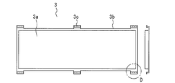
- FIG. 13 is a front view and a plan view of a modified example of the display body of the display device according to the third embodiment.
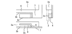
- FIG. 14 is an enlarged three-view view of the D portion of FIG.
- FIG. 15 is a three-view view when the separated portion is separated from the display body of FIG.
- the second separation portion 9 extends from the tip of the first separation portion 8 along the back surface of the housing 2 in a direction opposite to the direction of the side surface of the display portion 3a.
- the separation portion 3c can be reduced while ensuring the size of the surface of the second separation portion 9. As a result, the manufacturing cost of the display device 1 can be reduced by reducing the material of the separation unit 3c.
- FIG. 16 is a front view and a plan view of the display body of the display device according to the fourth embodiment.
- FIG. 17 is an enlarged three-view view of the E portion of FIG.
- FIG. 18 is a three-view view when the separated portion is separated from the display body of FIG.
- the same or corresponding parts as those of the third embodiment are designated by the same reference numerals. The explanation of this part is omitted.
- the second separating portion 9 extends from the tip of the first separating portion 8 along the side surface of the display portion 3a in a direction away from the second flange portion 7.
- the thickness of the second separation portion 9 is the same as the thickness of the second flange portion 7.
- the thickness of the second separation portion 9 is the same as the thickness of the second flange portion 7. Therefore, the same mounting body 4 can be used depending on whether the separated portion 3c is not separated or separated. As a result, the manufacturing cost of the display device 1 can be reduced.
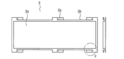
- FIG. 19 is a front view and a plan view of a first modification of the display body of the display device according to the fourth embodiment.
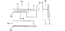
- FIG. 20 is an enlarged three-view view of the F portion of FIG. 21 is a cross-sectional view taken along the line GG of FIG. 20.
- FIG. 22 is a three-view view when the separated portion is separated from the display body of FIG. 20.
- FIG. 23 is a cross-sectional view taken along the line HU of FIG. 22.
- the separation portion 3c is adjacent to the second flange portion 7.
- the separating portion 3c is connected to the first flange portion 6.
- the second separation portion 9 extends from the tip of the first separation portion 8 along the back surface of the housing 2 in a direction opposite to the direction of the side surface of the display portion 3a.
- the same mounting body 4 can be used depending on whether the separation portion 3c is not separated or separated. As a result, the manufacturing cost of the display device 1 can be reduced.
- FIG. 24 is a front view and a plan view of the display body of the display device according to the fourth embodiment.
- FIG. 25 is an enlarged three-view view of part I of FIG. 24.
- FIG. 26 is a three-view view when the separated portion is separated from the display body of FIG. 25.
- the second modification extends from the tip of the first separation portion 8 toward the second flange portion 7 along the side surface of the display portion 3a.
- the second separation portion 9 overlaps with the second flange portion 7.
- the mounting body 4 can be mounted at the same position of the housing 2 depending on whether the separating portion 3c is not separated or separated.
- the display device 1 can be made smaller by simplifying the structure of the display device 1.
- FIG. 27 is a front view and a plan view of the display body of the display device according to the fifth embodiment.
- FIG. 28 is an enlarged three-view view of the J portion of FIG. 27.
- FIG. 29 is a cross-sectional view taken along the line KK of FIG. 28.
- FIG. 30 is a three-view view when the separated portion is separated from the display body of FIG. 28.
- FIG. 31 is a cross-sectional view taken along the line LL of FIG.
- the same or corresponding parts as those of the first embodiment are designated by the same reference numerals. The explanation of this part is omitted.
- the flange portion 3b is provided with a through hole 10.
- the through hole 10 is formed in the connecting portion between the first flange portion 6 and the second flange portion 7.
- the separation portion 3c protrudes from the connecting portion between the first flange portion 6 and the second flange portion 7 toward the back surface of the housing 2 around the through hole 10.
- the separation portion 3c protrudes from the flange portion 3b toward the back surface of the housing 2 around the through hole 10. Therefore, it is possible to prevent the flange portion 3b from being damaged when the separation portion 3c is separated from the flange portion 3b.
- the display device 1 of the first to fifth embodiments may be applied to other than the elevator.
- the display body of the display device of the present disclosure can be used for the elevator system.
- 1 display device 2 housing, 3 display body, 3a display part, 3b collar part, 3c separation part, 4 mounting body, 5 indicator, 6 1st collar part, 7 2nd collar part, 8 1st separation part, 9 2nd separation part, 10 through holes
Landscapes
- Physics & Mathematics (AREA)
- General Physics & Mathematics (AREA)
- Engineering & Computer Science (AREA)
- Theoretical Computer Science (AREA)
- Devices For Indicating Variable Information By Combining Individual Elements (AREA)
- Elevator Control (AREA)
Priority Applications (3)
| Application Number | Priority Date | Filing Date | Title |
|---|---|---|---|
| JP2022522484A JP7371773B2 (ja) | 2020-05-15 | 2020-05-15 | 表示装置の表示体 |
| PCT/JP2020/019506 WO2021229811A1 (ja) | 2020-05-15 | 2020-05-15 | 表示装置の表示体 |
| CN202080097848.4A CN115461799A (zh) | 2020-05-15 | 2020-05-15 | 显示装置的显示体 |
Applications Claiming Priority (1)
| Application Number | Priority Date | Filing Date | Title |
|---|---|---|---|
| PCT/JP2020/019506 WO2021229811A1 (ja) | 2020-05-15 | 2020-05-15 | 表示装置の表示体 |
Publications (1)
| Publication Number | Publication Date |
|---|---|
| WO2021229811A1 true WO2021229811A1 (ja) | 2021-11-18 |
Family
ID=78525631
Family Applications (1)
| Application Number | Title | Priority Date | Filing Date |
|---|---|---|---|
| PCT/JP2020/019506 Ceased WO2021229811A1 (ja) | 2020-05-15 | 2020-05-15 | 表示装置の表示体 |
Country Status (3)
| Country | Link |
|---|---|
| JP (1) | JP7371773B2 (https=) |
| CN (1) | CN115461799A (https=) |
| WO (1) | WO2021229811A1 (https=) |
Citations (5)
| Publication number | Priority date | Publication date | Assignee | Title |
|---|---|---|---|---|
| JPS532854A (en) * | 1976-06-28 | 1978-01-12 | Hitachi Ltd | Indicator for elevator |
| JPS59124664A (ja) * | 1982-12-28 | 1984-07-18 | 株式会社東芝 | エレベ−タのかご室内操作盤 |
| JPS6429368U (https=) * | 1987-08-12 | 1989-02-21 | ||
| JP2002179351A (ja) * | 2000-12-19 | 2002-06-26 | Fujitec Co Ltd | エレベータ用機器 |
| WO2011067837A1 (ja) * | 2009-12-02 | 2011-06-09 | 三菱電機株式会社 | エレベータ用操作表示器 |
Family Cites Families (10)
| Publication number | Priority date | Publication date | Assignee | Title |
|---|---|---|---|---|
| JPS6342675U (https=) * | 1986-09-08 | 1988-03-22 | ||
| JPS63194882U (https=) * | 1987-06-02 | 1988-12-15 | ||
| JPH0299874U (https=) * | 1989-01-25 | 1990-08-08 | ||
| JPH1173128A (ja) * | 1997-08-28 | 1999-03-16 | Harness Sogo Gijutsu Kenkyusho:Kk | 車載用表示装置 |
| KR20060034528A (ko) | 2004-10-19 | 2006-04-24 | 삼성전자주식회사 | 표시 패널의 높이를 조절할 수 있는 표시 장치 |
| US20110267751A1 (en) | 2009-01-23 | 2011-11-03 | Sharp Kabushiki Kaisha | Display device and frame mountable on the display device |
| JP2011051789A (ja) | 2009-09-04 | 2011-03-17 | Toshiba Elevator Co Ltd | エレベータの乗籠の音響装置 |
| JP2013173586A (ja) | 2012-02-24 | 2013-09-05 | Mitsubishi Electric Building Techno Service Co Ltd | エレベータの乗場位置表示器 |
| TWI495933B (zh) | 2012-10-17 | 2015-08-11 | Au Optronics Corp | 顯示裝置 |
| WO2015029719A1 (ja) * | 2013-08-26 | 2015-03-05 | 堺ディスプレイプロダクト株式会社 | 照明装置及び表示装置 |
-
2020
- 2020-05-15 WO PCT/JP2020/019506 patent/WO2021229811A1/ja not_active Ceased
- 2020-05-15 CN CN202080097848.4A patent/CN115461799A/zh active Pending
- 2020-05-15 JP JP2022522484A patent/JP7371773B2/ja active Active
Patent Citations (5)
| Publication number | Priority date | Publication date | Assignee | Title |
|---|---|---|---|---|
| JPS532854A (en) * | 1976-06-28 | 1978-01-12 | Hitachi Ltd | Indicator for elevator |
| JPS59124664A (ja) * | 1982-12-28 | 1984-07-18 | 株式会社東芝 | エレベ−タのかご室内操作盤 |
| JPS6429368U (https=) * | 1987-08-12 | 1989-02-21 | ||
| JP2002179351A (ja) * | 2000-12-19 | 2002-06-26 | Fujitec Co Ltd | エレベータ用機器 |
| WO2011067837A1 (ja) * | 2009-12-02 | 2011-06-09 | 三菱電機株式会社 | エレベータ用操作表示器 |
Also Published As
| Publication number | Publication date |
|---|---|
| JPWO2021229811A1 (https=) | 2021-11-18 |
| JP7371773B2 (ja) | 2023-10-31 |
| CN115461799A (zh) | 2022-12-09 |
Similar Documents
| Publication | Publication Date | Title |
|---|---|---|
| US20010026336A1 (en) | LCD device having an improved backlight unit | |
| USD993794S1 (en) | Operation device for liquid leakage prediction system | |
| US7875819B2 (en) | Panel operator structure for electronic equipment | |
| JP2016010098A (ja) | アンテナユニット | |
| US20120086883A1 (en) | Backlight unit and liquid crystal display device | |
| WO2013069212A1 (ja) | 携帯端末 | |
| US10144363B2 (en) | Mounting assembly of vehicular utility part mounting member and vehicular interior part | |
| US10397512B2 (en) | Display device with slimmer border portion | |
| US7619174B2 (en) | Illuminated switch device | |
| JP2010027273A (ja) | 透光式操作子ユニット | |
| WO2021229811A1 (ja) | 表示装置の表示体 | |
| USD917358S1 (en) | Instrument panel for automobile | |
| WO2017110519A1 (ja) | 死角補助装置 | |
| JP2012204271A (ja) | 表示モジュールおよび表示装置 | |
| US11285811B2 (en) | Vehicle display device pointer | |
| JP3590745B2 (ja) | 計器の見返し固定構造 | |
| JP6949643B2 (ja) | 照明装置及び表示装置 | |
| JP7736166B2 (ja) | 押しボタン照明構造及びそれを備えた車載機器 | |
| JPWO2020153474A1 (ja) | ヘッドアップディスプレイ装置 | |
| US20090108753A1 (en) | Plasma display device and method of manufacturing the same | |
| JP6821499B2 (ja) | 外装構造 | |
| JP2022048562A (ja) | ルーフライニングの取付構造 | |
| JP4796899B2 (ja) | バックライト装置 | |
| JPH10142592A (ja) | 車両用液晶表示装置 | |
| JP3751190B2 (ja) | 電子機器のパネル保護構造 |
Legal Events
| Date | Code | Title | Description |
|---|---|---|---|
| 121 | Ep: the epo has been informed by wipo that ep was designated in this application |
Ref document number: 20935547 Country of ref document: EP Kind code of ref document: A1 |
|
| ENP | Entry into the national phase |
Ref document number: 2022522484 Country of ref document: JP Kind code of ref document: A |
|
| NENP | Non-entry into the national phase |
Ref country code: DE |
|
| 122 | Ep: pct application non-entry in european phase |
Ref document number: 20935547 Country of ref document: EP Kind code of ref document: A1 |