WO2021229807A1 - かご形回転子の製造方法およびかご形回転子 - Google Patents
かご形回転子の製造方法およびかご形回転子 Download PDFInfo
- Publication number
- WO2021229807A1 WO2021229807A1 PCT/JP2020/019496 JP2020019496W WO2021229807A1 WO 2021229807 A1 WO2021229807 A1 WO 2021229807A1 JP 2020019496 W JP2020019496 W JP 2020019496W WO 2021229807 A1 WO2021229807 A1 WO 2021229807A1
- Authority
- WO
- WIPO (PCT)
- Prior art keywords
- insulating layer
- slot
- insulating
- rotor
- particles
- Prior art date
- Legal status (The legal status is an assumption and is not a legal conclusion. Google has not performed a legal analysis and makes no representation as to the accuracy of the status listed.)
- Ceased
Links
Images


Classifications
-
- H—ELECTRICITY
- H02—GENERATION; CONVERSION OR DISTRIBUTION OF ELECTRIC POWER
- H02K—DYNAMO-ELECTRIC MACHINES
- H02K15/00—Processes or apparatus specially adapted for manufacturing, assembling, maintaining or repairing of dynamo-electric machines
- H02K15/02—Processes or apparatus specially adapted for manufacturing, assembling, maintaining or repairing of dynamo-electric machines of stator or rotor bodies
-
- H—ELECTRICITY
- H02—GENERATION; CONVERSION OR DISTRIBUTION OF ELECTRIC POWER
- H02K—DYNAMO-ELECTRIC MACHINES
- H02K17/00—Asynchronous induction motors; Asynchronous induction generators
- H02K17/02—Asynchronous induction motors
- H02K17/16—Asynchronous induction motors having rotors with internally short-circuited windings, e.g. cage rotors
Definitions
- This disclosure relates to a method for manufacturing a cage rotor provided in an induction motor and a cage rotor.
- Induction motors are the most used among motors because they are robust and can be started by connecting them directly to a power source.
- the cage rotor used in an induction motor has a conductor housed in each of a plurality of slots in the rotor core and two short-circuit rings connected to each conductor.
- a cross current may be generated in a cage rotor. Since the cross current is a current component that does not contribute to the drive of the induction motor, the drive efficiency of the induction motor is lowered due to the occurrence of the cross flow.
- Patent Document 1 a water-soluble inorganic insulating treatment liquid is applied to each slot formed in the rotor core, then an inorganic flocculant is applied, and the entire rotor core is dried to insulate the inorganic flocculant from the inorganic flocculant.
- a method for solidifying the treatment liquid is disclosed. According to the method disclosed in Patent Document 1, the inorganic particles contained in the inorganic insulating treatment liquid are aggregated by the application of the inorganic flocculant, so that an insulating layer is formed on the inner peripheral surface of each slot. Further, a conductor is formed in each slot by casting a metal material which is a material of the conductor into each slot in which the insulating layer is formed. By forming an insulating layer in each slot, electrical insulation between each conductor and the rotor core is ensured.
- Patent Document 1 requires two coating steps, such as coating an inorganic insulating treatment liquid and then applying an inorganic flocculant. According to the conventional method, there is a problem that it is difficult to improve the production efficiency of the squirrel-cage rotor because two coating steps are required in the production of the squirrel-cage rotor.
- the present disclosure has been made in view of the above, and an object thereof is to obtain a method for manufacturing a squirrel-cage rotor that can improve the production efficiency of the squirrel-cage rotor.
- the method for manufacturing a cage rotor according to the present disclosure is centered on a rotor core which is a laminated body of a plurality of steel plates and a rotation axis in the rotor core. It is a method of manufacturing a cage rotor having a conductor housed in each of a plurality of slots arranged in the circumferential direction of a circle.
- the method for manufacturing a cage rotor according to the present disclosure includes a step of forming an insulating layer in a slot by applying an insulating paint to the inner peripheral surface of the slot included in the plurality of slots.
- the insulating coating material includes a silicone resin which is at least one of a silicone resin having a methylphenyl group and a silicone resin modified with an alkyd resin, and aggregated particles of inorganic compound particles having a property of self-aggregating primary particles. Containing with a diluting solvent.
- the method for manufacturing a squirrel-cage rotor according to the present disclosure has the effect of improving the production efficiency of the squirrel-cage rotor.
- FIG. 1 A perspective view showing a rotor core of the induction motor according to the first embodiment. Top view showing a part of the rotor core shown in FIG. The figure which shows the conductor provided in the rotor core shown in FIG. Schematic diagram of agglomerated particles used in the manufacture of the rotor core shown in FIG. Top view of the slot provided in the rotor core shown in FIG. A cross-sectional view showing a portion of the rotor core shown in FIG. 2 in which one slot is provided. A perspective view showing a part of the rotor core of the induction motor according to the second embodiment. Top view showing a part of the rotor core of the induction motor according to the third embodiment.
- FIG. 1 is a diagram showing an induction motor according to the first embodiment.
- the induction motor 1 according to the first embodiment has a cylindrical stator 2, a rotor 3 surrounded by the stator 2 and driven to rotate, and a shaft 4 provided at the center of the rotor 3.
- the rotor 3 is a cage rotor.
- the rotation axis AX is the rotation center of the rotor 3.
- the vertical cross section of the induction motor 1 is shown on the right side of the rotation shaft AX. Further, the side surface of the induction motor 1 is shown on the left side of the rotation shaft AX.
- the direction of the rotation axis AX may be referred to as an axial direction.
- the housing 5, which is the outer shell of the induction motor 1, has a cylindrical frame 6 and an end plate 7.
- the frame 6 includes a bottom portion 6a at one end of the frame 6 in the axial direction.
- the other end of the frame 6 in the axial direction is open.
- the end plate 7 is provided at the open end of the frame 6.
- the stator 2 is fitted inside the frame 6.
- the shaft 4 penetrates the housing 5.
- the shaft 4 transmits the rotational force of the rotor 3 to the outside of the induction motor 1.
- the induction motor 1 has two bearings 8 that rotatably support the shaft 4.
- One bearing 8 is provided on the bottom 6a of the frame 6.
- the other bearing 8 is provided on the end plate 7.
- the rotor 3 has a rotor core 9 which is a laminated body of a plurality of steel plates.
- the rotor core 9 is provided with a plurality of slots 10 arranged in the circumferential direction of a circle centered on the rotation axis AX.
- a conductor 11 is housed in each of the plurality of slots 10.
- the material of the conductor 11 is a conductive metal material, for example, aluminum.
- the rotor 3 has two short circuit rings 12.
- One short-circuit ring 12 is provided at one end of the rotor core 9 in the axial direction.
- the other short-circuit ring 12 is provided at the other end of the rotor core 9 in the axial direction.
- Each short-circuit ring 12 is connected to each of the plurality of conductors 11.
- the material of each short-circuit ring 12 is the same as that of the conductor 11, for example aluminum.
- FIG. 2 is a perspective view showing a rotor core of the induction motor according to the first embodiment.
- the steel plate 9a constituting the rotor core 9 is an annular thin plate which is a magnetic material.
- the plurality of steel plates 9a are laminated in the axial direction. Each of the plurality of steel plates 9a is fixed to each other by caulking, welding or bonding. Each of the plurality of steel plates 9a does not have to be fixed to each other.
- Each of the plurality of slots 10 is arranged at equal intervals in the circumferential direction.
- An insulating layer 13 is provided on the inner peripheral surface of each slot 10.
- the insulating layer 13 is provided only on the inner peripheral surface of each slot 10 of the rotor core 9.
- Each conductor 11 is formed by casting aluminum into a slot 10 provided with an insulating layer 13.
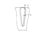
- FIG. 3 is a top view showing a part of the rotor core shown in FIG. 2.
- FIG. 3 shows the upper surface of a portion of the rotor core 9 in which one slot 10 is provided.
- the shape of the slot 10 in the cross section shown in FIG. 3 is a shape in which the width in the circumferential direction is increased as the distance from the rotation axis AX increases.
- the insulating layer 13 is provided on the entire inner peripheral surface of the slot 10. The insulating layer 13 surrounds the entire circumference of the conductor 11.
- FIG. 4 is a diagram showing a conductor provided in the rotor core shown in FIG. 2.
- FIG. 4 shows a part of the rotor core 9. Further, the conductor 11 provided inside the rotor core 9 is shown by a broken line.
- Holes constituting the slot 10 are formed in each of the plurality of steel plates 9a constituting the rotor core 9.
- Each of the plurality of steel plates 9a has the same shape.
- each of the plurality of slots 10 is tilted with respect to the rotation axis AX.
- each of the plurality of slots 10 is twisted in the circumferential direction from the state parallel to the rotation axis AX.
- the insulating layer 13 is formed by applying an insulating paint to the inner peripheral surface of each of the plurality of slots 10 and drying and heating the applied insulating paint.
- the insulating coating material includes a silicone resin having a methylphenyl group and a silicone resin modified with an alkyd resin, which is at least one of them. Further, the insulating coating material contains agglomerated particles of inorganic compound particles and a diluting solvent.
- the inorganic compound particles are inorganic compound particles in which the specific surface area of the primary particles is contained in the range of 0.5 m 2 / g to 20 m 2 / g.
- the coated insulating paint is dried by leaving the rotor core 9 coated with the insulating paint in the air. The heating of the insulating paint is performed by a pre-drying oven.
- the silicone resin having a methylphenyl group is a silicone resin having a linear structure in which a methylphenyl group is introduced.
- the silicone resin having a methylphenyl group is one in which a phenyl group (C 6 H 5 ) is introduced into the side chain of a part of the polysiloxane contained in the silicone resin.
- the following chemical formula (1) shows an example of the chemical structure of a silicone resin having a methylphenyl group.
- the heat resistance of the silicone resin is improved by the introduction of the methylphenyl group.
- the silicone resin having a methylphenyl group in the insulating paint decomposition and carbonization of the insulating paint do not occur at a temperature of about 250 degrees, and the mechanical strength of the insulating paint during drying and heating is improved. Can be made to.
- the insulating paint is exposed to a temperature of about 700 degrees for a period of about 10 seconds in the aluminum die casting process for forming the conductor 11.
- the silicone resin having a methylphenyl group in the insulating paint the insulating paint can secure the short-term heat resistance required for the aluminum die casting treatment.
- the silicone resin having a methylphenyl group is preferably a polymer of a trimer or more. Further, the molecular weight of the silicone resin having a methylphenyl group is preferably 1000 or more.
- the silicone resin modified with the alkyd resin is obtained by the reaction between the oligomer which is the silicone resin and the alkyd resin, or the reaction between the polymer which is the silicone resin and the alkyd resin.
- the alkyd resin is a polymer ester obtained by a condensation reaction between a polybasic acid and a polyhydric alcohol.
- the following chemical formula (2) shows an example of the chemical structure of the alkyd resin.
- Silicone resin modified with alkyd resin has the flexibility and quick-drying characteristics of alkyd. By including the silicone resin modified with the alkyd resin in the insulating paint, the insulating paint can obtain flexibility and shorten the time required for curing.
- the insulating paint is a mixture of a silicone resin having a methylphenyl group and a silicone resin modified with an alkyd resin.
- the insulating coating material can obtain high heat resistance and high strength due to the silicone resin having a methylphenyl group, and quick-drying due to the silicone resin modified with the alkyd resin.
- the mixing ratio of the silicone resin having a methylphenyl group and the silicone resin modified with the alkyd resin is arbitrary. From the viewpoint of obtaining high heat resistance and high strength, the ratio of the silicone resin having a methylphenyl group in the insulating paint may be 50% or more, preferably 70% or more, and more preferably about 80%. be.
- the insulating coating material may contain at least one of a silicone resin having a methylphenyl group and a silicone resin modified with an alkyd resin.
- the aggregated particles of the inorganic compound particles may be any insulating inorganic compound.
- the insulating inorganic compound include silica (SiO 2 ), alumina (Al 2 O 3 ), zirconia (ZnO), and titania (TIO 2 ).
- the agglomerated particles one kind of inorganic compound may be used, or a plurality of kinds of inorganic compounds may be used in combination.
- the method for producing the inorganic compound particles is not particularly limited.
- the inorganic compound particles preferably have high activity on the particle surface. The higher the activity of the particle surface, the easier it is for the inorganic compound particles to self-aggregate. Since the self-aggregation of the inorganic compound particles is easy, the aggregated particles can be obtained without using an agglutinating agent. Inorganic compound particles aggregate by intramolecular interactions such as Van der Waals forces.
- FIG. 5 is a schematic diagram of agglomerated particles used in the production of the rotor core shown in FIG.
- the primary particles which are inorganic compound particles, aggregate due to the intramolecular interaction between the primary particles.
- the agglomerated particles 14 are agglomerates of primary particles having a diameter in the range of about 0.1 ⁇ m to 5 ⁇ m.
- the diameter of the agglomerated particles 14 is included in the range of about 0.5 ⁇ m to 20 ⁇ m.
- the specific surface area of the primary particle affects the mode of self-aggregation of the primary particles.
- the aggregated particles 14 having an appropriate diameter can be obtained by self-aggregation of the primary particles. .. Since the primary particles can be self-aggregated, the agglutinated particles 14 can be obtained without using an agglutinating agent. Since the coagulant is not used, the process of applying the coagulant is not required in the production of the cage rotor, so that the production efficiency of the cage rotor can be improved.
- the agglomerated particles included in the insulating paint are not limited to the agglomerated particles 14 composed only of the inorganic compound particles.
- the agglomerated particles may include inorganic compound particles and multi-component glass having a low melting point frit.
- low melting point frits include borate-based, silicate-based, germanate-based, vanadate-based, phosphate-based, arsenate-based, or telluride-based oxides.
- the low melting point frit one kind of oxide may be used, or a combination of two kinds of oxides may be used.
- FIG. 6 is a top view of a slot provided in the rotor core shown in FIG. 2.
- a plurality of holes 10a are formed in each of the steel plates 9a constituting the rotor core 9.
- Each of the plurality of steel plates 9a has the same shape in a plane perpendicular to the rotation axis AX. The shape is displaced by the length D in the circumferential direction for each of the plurality of steel plates 9a, and the plurality of steel plates 9a are laminated. The length D is shorter than the width of the hole 10a in the circumferential direction. As a result, the positions of the holes 10a in the laminated steel plates 9a are displaced by the length D in the circumferential direction. Note that FIG. 6 shows the slot 10 before the insulating layer 13 and the conductor 11 are formed.
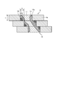
- FIG. 7 is a cross-sectional view showing a portion of the rotor core shown in FIG. 2 in which one slot is provided.
- Each of the steel plates 9a constituting the rotor core 9 is a flat plate having a thickness t. Since the positions of the holes 10a in the laminated steel plates 9a are displaced by the length D in the circumferential direction, the holes 10a in the steel plates 9a are connected in a diagonal direction with respect to the rotation axis AX. As a result, the slot 10 tilted with respect to the rotation axis AX is formed.
- FIG. 7 shows a cross section of three steel plates 9a stacked on top of each other, parallel to the rotation axis AX and along the circumferential direction.
- the slot 10 is a plane constituting the inner wall of the hole 10a and is composed of a plane parallel to the rotation axis AX and a plane perpendicular to the rotation axis AX.
- a step is formed on the inner peripheral surface of the slot 10 for each steel plate 9a.
- the insulating layer 13 is formed so as to cover the step of each steel plate 9a.
- the insulating layer 13 includes a silicone resin which is at least one of a silicone resin having a methylphenyl group and a silicone resin modified with an alkyd resin, and aggregated particles 14 of inorganic compound particles having a property of self-aggregating primary particles. including.
- the insulating layer 13 is provided only on the inner peripheral surface of the slot 10.
- FIG. 7 schematically shows agglomerated particles 14 of inorganic compound particles contained in the insulating layer 13.
- the diameter d of the agglomerated particles 14 is included in the range of about 0.5 ⁇ m to 20 ⁇ m.
- the diameter d of the agglomerated particles 14 is shorter than the length D and shorter than the thickness t of each of the plurality of steel plates 9a in the axial direction.
- the agglomerated particles 14 are filled in the stepped portion on the inner peripheral surface of the slot 10.
- the agglomerated particles 14 exhibit insulating properties in the insulating layer 13 and also function as a spacer for the insulating layer 13. By including the agglomerated particles 14 in the insulating layer 13, it is possible to form the insulating layer 13 having a thickness necessary for improving the driving efficiency of the induction motor 1. Further, when the insulating paint is applied, the agglomerated particles 14 also serve a function of leveling the step on the inner peripheral surface of the slot 10. By smoothing the step on the inner peripheral surface of the slot 10, it is possible to improve the fluidity of aluminum when casting aluminum into the slot 10.
- the diluting solvent contained in the insulating paint includes an organic solvent having a boiling point of 100 degrees or higher.
- the concentration of the organic solvent in the diluting solvent may be 20 wt% or more, preferably 40 wt% or more, and more preferably 60 wt% or more.
- the diluting solvent is a solvent capable of dissolving a silicone resin having a methylphenyl group, which is a silicone resin contained in an insulating paint, and a silicone resin modified with an alkyd resin.
- a single organic solvent having a boiling point of 100 degrees or higher is used, or a plurality of kinds of organic solvents having a boiling point of 100 degrees or higher are used.
- the diluting solvent a mixture of an organic solvent having a boiling point of 100 degrees or higher and another solvent may be used.
- the solvent used in combination with the organic solvent having a boiling point of 100 ° C. or higher is preferably a solvent having a boiling point of 30 ° C. or higher, and more preferably a solvent having a boiling point of 30 ° C. to 50 ° C.
- the sprayed particles of the silicone resin composition are adhered when the insulating paint is applied by spraying. It is possible to prevent the diluting solvent from volatilizing until it reaches the rotor core 9 which is the body. This makes it possible to secure the viscosity of the insulating paint when applying the insulating paint. Further, it is possible to reduce the unevenness on the surface of the insulating layer 13 and prevent the insulating layer 13 from cracking.
- Examples of the organic solvent having a boiling point of 100 degrees or higher include toluene, xylene, methyl isobutyl ketone, butyl acetate, anisole, N, N-dimethylacetamide (DMAc), dimethyl sulfoxide (DMSO), and methyl benzoate.
- Examples of the solvent used in combination with the organic solvent having a boiling point of 100 ° C. or higher include acetone, tetrahydrofuran (THF) and the like.
- the organic solvent having a boiling point of 100 degrees or higher volatilizes by heating in the aluminum die casting treatment, it is removed before the heating step of the silicone resin. Therefore, even if the insulating paint contains an organic solvent having a high boiling point of 100 degrees or higher, it is possible to suppress the generation of bubbles when the insulating paint is cured.
- the concentration of the agglomerated particles 14 in the insulating paint excluding the diluting solvent is 30 wt% to 40 wt%.
- the viscosity of the insulating coating material may be contained in the range of 10 mPa ⁇ s to 1000 mPa ⁇ s, preferably in the range of 10 mPa ⁇ s to 60 mPa ⁇ s, and more preferably in the range of 10 mPa ⁇ s to 20 mPa ⁇ s. Is done.
- the insulating paint By setting the particle concentration and viscosity as described above, it is possible to apply the insulating paint by spraying. As a result, the insulating paint can be easily applied, and the insulating paint can be applied only to a necessary range. Further, by setting the particle concentration and the viscosity as described above, the insulating paint can be filled in the stepped portion on the inner peripheral surface of the slot 10. Since the insulating paint can be permeated into the gap of the rotor core 9 where aluminum may enter, the gap can be filled with the insulating paint before the aluminum is cast. If the viscosity of the insulating paint is less than 10 mPa ⁇ s, the insulating paint is excessively diluted and the thickness of the insulating layer 13 becomes insufficient.
- the viscosity of the insulating paint exceeds 1000 mPa ⁇ s, it becomes difficult to apply the insulating paint by spraying. Further, when the viscosity of the insulating paint exceeds 60 mPa ⁇ s, the insulating paint can be applied by spraying, but it becomes difficult to form the insulating layer 13 having a uniform thickness.
- the induction motor 1 can suppress the generation of cross current by forming the insulating layer 13 in each of the plurality of slots 10 provided in the rotor core 9, and the drive efficiency is improved. Is possible. In the production of the rotor 3, a step of applying a flocculant is not required in addition to the step of applying the insulating paint. Therefore, it is possible to improve the production efficiency of the rotor 3.
- FIG. 8 is a perspective view showing a part of the rotor core of the induction motor according to the second embodiment.
- the insulating layer 13 is provided at the central portion of the slot 10 in the axial direction.
- the same components as those in the first embodiment are designated by the same reference numerals, and the configurations different from those in the first embodiment will be mainly described.
- FIG. 8 shows an insulating layer 13 provided in one slot 10.
- the length l of the insulating layer 13 in the axial direction is 85% or more of the total length L of the slot 10 in the axial direction. Insulating layers 13 are not provided at both ends of the slot 10 in the axial direction.
- the insulating layer 13 is formed in the central portion of the slot 10 in the axial direction in a range of at least 85% with respect to the total length L of the slot 10. ..
- the induction motor 1 can suppress the generation of cross current and can improve the drive efficiency.
- the second embodiment it is possible to reduce the amount of the insulating paint used in the manufacture of the rotor 3 by eliminating the need to apply the insulating paint at both ends of the slot 10.
- FIG. 9 is a top view showing a part of the rotor core of the induction motor according to the third embodiment.
- the insulating layer 13 is provided on the outer edge side portion of the slot 10, which is the portion opposite to the rotation axis AX.
- the same components as those in the first or second embodiment are designated by the same reference numerals, and the configurations different from those in the first or second embodiment will be mainly described.
- FIG. 9 shows the upper surface of a portion of the rotor core 9 in which one slot 10 is provided.
- the length h of the insulating layer 13 in the radial direction of the circle centered on the rotation axis AX is 60% or more of the length H of the slot 10 in the radial direction.
- the insulating layer 13 is not provided in the portion of the slot 10 on the rotating shaft AX side.
- the insulating layer 13 is formed on the outer edge side portion of the slot 10.
- the insulating layer 13 is formed in a range of at least 60% of the length H of the slot 10 in the radial direction of the circle centered on the rotation axis AX in the slot 10.
- the drive efficiency of the induction motor 1 is reduced by the harmonic flux interlinking with the conductor 11.
- the harmonic flux is generated by the current of the harmonic component, which is a component having a frequency higher than the drive frequency of the rotor 3, flowing through the rotor core 9. Since the harmonic flux passes only through the outer edge portion of the rotor core 9, cross currents are likely to occur in the outer edge side portion of the slot 10.
- the induction motor 1 can suppress the generation of cross current and can improve the drive efficiency.
- the amount of the insulating paint used in the manufacture of the rotor 3 can be reduced by eliminating the need to apply the insulating paint to the portion of the slot 10 on the rotating shaft AX side.
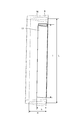
- FIG. 10 is a perspective view showing a part of the rotor core of the induction motor according to the fourth embodiment.
- the insulating layer 13 is provided in the central portion of the slot 10 in the axial direction as in the second embodiment, and is provided on the outer edge side portion of the slot 10 as in the third embodiment. It is provided.
- the same components as those in the first to third embodiments are designated by the same reference numerals, and the configurations different from those in the first to third embodiments will be mainly described.
- FIG. 10 shows an insulating layer 13 provided in one slot 10.
- the length l of the insulating layer 13 in the axial direction is 85% or more of the total length L of the slot 10 in the axial direction. Insulating layers 13 are not provided at both ends of the slot 10 in the axial direction.
- the insulating layer 13 is formed in the central portion of the slot 10 in the axial direction in a range of at least 85% with respect to the total length L of the slot 10. ..
- the length h of the insulating layer 13 in the radial direction of the circle centered on the rotation axis AX is 60% or more of the length H of the slot 10 in the radial direction.
- the insulating layer 13 is not provided in the portion of the slot 10 on the rotating shaft AX side.
- the insulating layer 13 is formed on the outer edge side portion of the slot 10 in the step of forming the insulating layer.
- the insulating layer 13 is formed in a range of at least 60% of the length of the slot 10 in the radial direction of the circle centered on the rotation axis AX in the slot 10.
- the amount of the insulating paint used in the production of the rotor 3 can be reduced as in the cases of the second and third embodiments. Further, as in the case of the second embodiment, the workability in the manufacture of the rotor 3 can be improved, so that the production efficiency of the rotor 3 can be improved.
- FIG. 11 is a perspective view showing a rotor core of the induction motor according to the fifth embodiment.
- the insulating layer 13 is provided in each of the plurality of slots 10 provided in the rotor core 9 in every other slot 10 in the circumferential direction of the circle centered on the rotation axis AX. ing.
- the same components as those in the first to fourth embodiments are designated by the same reference numerals, and the configurations different from those in the first to fourth embodiments will be mainly described.
- slots 10 provided with an insulating layer 13 and slots 10 not provided with an insulating layer 13 are alternately arranged in the circumferential direction.
- the insulating layer 13 is provided on the entire inner peripheral surface of the slot 10 as in the first embodiment.
- the insulating layer 13 is formed in each of every other slot 10 in the circumferential direction.
- the insulating layer 13 may be provided in the same manner as in the second, third, or fourth embodiments.
- Cross current mainly occurs between the conductors 11 of the slots 10 adjacent to each other. Therefore, even if the insulating layer 13 is provided in every other slot 10 in the circumferential direction, it is possible to reduce the occurrence of cross current in the rotor core 9.
- the induction motor 1 makes it possible to suppress the generation of cross currents and improve the drive efficiency.
- the fifth embodiment it is possible to reduce the amount of the insulating paint used in the manufacture of the rotor 3 by eliminating the need to apply the insulating paint in a part of the plurality of slots 10.
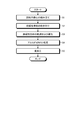
- FIG. 12 is a flowchart showing a procedure of a method for manufacturing a cage rotor according to the sixth embodiment.
- the method for manufacturing a cage rotor according to the sixth embodiment includes the steps from step S1 to step S5.
- Step S1 is an assembly process of the rotor core 9.
- Step S2 is a step of spraying the insulating paint.
- Step S3 is a step of drying and curing the insulating paint.
- Step S4 is an aluminum die casting process.
- Step S5 is a post-processing step.
- the rotor core 9 is assembled by superimposing a plurality of die-cut steel plates 9a on each other.
- a plurality of steel plates 9a are laminated by displacing the steel plates 9a by a constant length in the circumferential direction of a circle centered on the rotation axis AX.
- a silicone resin having a methylphenyl group, a silicone resin modified by an alkyd resin, a silicone resin, agglomerated particles of inorganic compound particles, and a diluting solvent are mixed.
- an insulating paint is made.
- the method of mixing and stirring the material of the insulating paint is arbitrary. In this step, it is sufficient that the aggregated particles of the inorganic compound particles can be dispersed, and the material of the insulating coating material can be mixed and stirred by means usually used in the technical field of rotor production.
- a general rotating / revolving stirrer, a high-pressure shear disperser, a homogenizer, a high-speed stirrer, or the like can be used.
- the prepared insulating paint is sprayed onto the rotor core 9 by spraying it.
- the insulating paint is applied to the inner peripheral surface of the slot 10 by injecting the insulating paint from the upper surface side of the rotor core 9 of the slot 10 toward the inside of the slot 10.
- the amount of insulating paint to be sprayed is adjusted in order to adjust the thickness of the insulating paint on the inner peripheral surface and to prevent excess or deficiency of the insulating paint to be sprayed.
- the time for spraying the insulating paint is precisely controlled.
- the amount of the insulating paint sprayed may be excessive, and the thickness of the insulating paint on the inner peripheral surface may be excessive.
- a part of the sprayed insulating paint may drip from the slot 10. Insulating paint may penetrate inside the rotor core 9. If the time for spraying the insulating paint is too short, the amount of the insulating paint sprayed may be insufficient, and the thickness of the insulating paint on the inner peripheral surface may be insufficient. Further, since the insulating paint does not spread on the inner peripheral surface, the thickness of the insulating paint covering the inner peripheral surface may not be uniform.
- the insulating paint is applied only to the inner peripheral surface of the slot 10.
- the insulating paint can be applied only in the range where the insulating layer 13 is formed.
- the insulating paint is applied to a portion where the insulating layer 13 is unnecessary.
- impurities adhering to the rotor core 9 are mixed in the insulating paint in the case of spraying.
- the step of drying and curing the insulating paint consists of a first step of drying the insulating paint at room temperature and a second step of heating the insulating paint in the furnace.
- the first step the rotor core 9 coated with the insulating paint is left at room temperature for about 1 hour to vaporize the volatile components contained in the diluting solvent. If curing by heating is performed without going through the first step, vaporization of volatile components and curing of the silicone resin proceed at the same time, and bubbles may be generated on the surface and inside of the insulating paint. Since air bubbles can be a factor that lowers the dielectric strength, it is necessary to vaporize the volatile components before curing.
- the silicone resin having a methylphenyl group is cured by heating the rotor core 9 that has undergone drying of the insulating paint in a furnace.
- the heating temperature and heating time may be arbitrary as long as they can complete the curing of the silicone resin and do not cause deterioration of the silicone resin.
- the silicone resin is cured by heating at 250 degrees for 2 hours in the second step. If the heating temperature is too low or the heating time is too short, curing may be insufficient and the insulating paint may not solidify. If the heating time is too long, or if the heating time is too long, the silicone resin may deteriorate and the insulating performance of the insulating layer 13 may deteriorate.
- the conductor 11 is formed by casting aluminum into the slot 10 in which the insulating layer 13 is formed.
- the aluminum die casting process is carried out by means commonly used in the technical field of rotor manufacturing.
- the shaft 4 is shrink-fitted into the rotor core 9 on which the conductor 11 is formed, and the rotor core 9 is turned.
- the post-processing step is carried out by means commonly used in the technical field of rotor manufacturing.
- FIG. 13 is a diagram for explaining the effect of the method for manufacturing a cage rotor according to the sixth embodiment.
- the stray load loss represents a stray load loss of the rotor 3 due to the occurrence of a cross current in the rotor core 9.
- the sprayability represents the property that a film of an insulating paint having an appropriate thickness can be formed by spraying the insulating paint.
- FIG. 13 shows each condition regarding the material and viscosity of the insulating coating material for each of Example 1 to Example 20 and Comparative Example 1 to Comparative Example 8.
- the silicone resin a silicone resin having a methylphenyl group and a silicone resin modified with an alkyd resin are used.
- methylphenyl represents a silicone resin having a methylphenyl group.
- alkyd represents a silicone resin modified with an alkyd resin.
- Example 1 the specific surface area of the primary particles which are inorganic compound particles is 10 m 2 / g, the particle size which is the diameter of the agglomerated particles 14 is 10 ⁇ m, and the concentration of the agglomerated particles 14 in the insulating coating material excluding the diluting solvent is. It is 35 wt%.
- the diluting solvent is a mixed solvent of xylene and toluene.
- the viscosity of the insulating paint is 15 mPa ⁇ s.
- At least one of the conditions for the inorganic compound particles that is, the specific surface area, the particle size and the concentration, and the viscosity of the insulating coating material, is an example. It is different from the case of 1.
- FIG. 13 shows the evaluation results of each item of the drifting load loss reduction effect and the sprayability for each of Example 1-20 and Comparative Example 1-8, and the comprehensive evaluation of each item.
- Each of the evaluation for each item and the comprehensive evaluation is represented by four “A”, “B”, “C” and “D”.
- “A” represents the highest evaluation among the four “A”, “B”, “C” and “D”.
- the evaluation is lowered in the order of "A”, “B", “C” and “D”.
- “C” represents an evaluation corresponding to the case where the insulating paint is not applied.
- sprayability indicates that spraying is not possible.
- the action and effect of having the diameter of the agglomerated particles 14 in the range of 0.5 ⁇ m to 20 ⁇ m can be explained by comparison between Examples 1-3, 15-20 and Comparative Examples 1, 2, 7, 8. ..
- the particle sizes in Examples 1-3 are 10 ⁇ m, 15 ⁇ m, and 20 ⁇ m, respectively, and all of them are included in the range of 0.5 ⁇ m to 20 ⁇ m.
- the particle sizes in Comparative Examples 1, 2, 7 and 8 were 0.3 ⁇ m, 27 ⁇ m, 35 ⁇ m and 0.4 ⁇ m, respectively, and none of them was included in the range of 0.5 ⁇ m to 20 ⁇ m.
- the agglomerated particles 14 fulfill a function of improving the dielectric strength of the entire insulating layer 13. Further, the agglomerated particles 14 function as a spacer for giving the insulating layer 13 a thickness for obtaining a required dielectric strength. In the case of Comparative Examples 1 and 8, since the particle size is less than 0.5 ⁇ m, it is not possible to form the insulating layer 13 having a thickness for obtaining the required dielectric strength. In the case of Comparative Example 2, since the particle size exceeds 20 ⁇ m, the aggregated particles 14 tend to settle in the liquid insulating coating material. Therefore, it becomes difficult to uniformly disperse the agglomerated particles 14 on the inner peripheral surface of the slot 10 and spray the insulating paint.
- Examples 1-3 and 15-20 since the particle size is included in the range of 0.5 ⁇ m to 20 ⁇ m in each case, the sedimentation of the agglomerated particles 14 in the insulating coating material can be reduced. , The agglomerated particles 14 can be uniformly dispersed and the insulating paint can be sprayed. Further, the insulating layer 13 having a thickness for obtaining the required dielectric strength can be formed. Therefore, in Examples 1-3 and 15-20, the effect of reducing the drifting load loss is high.
- the action and effect of having the specific surface area of the primary particles, which are inorganic compound particles, contained in the range of 0.5 m 2 / g to 20 m 2 / g are obtained by comparing Examples 17-20 with Comparative Examples 1 and 2. I can explain.
- the specific surface areas of Examples 17-20 are 0.5 m 2 / g, 1 m 2 / g, 5 m 2 / g, and 20 m 2 / g, respectively, and all of them range from 0.5 m 2 / g to 20 m 2 / g. Included in the range.
- the specific surface area in Comparative Examples 1 and 2 are each 100m 2 /g,0.3m 2 / g, none contain from 0.5 m 2 / g in the range of 20 m 2 / g ..
- the specific surface area of the primary particle changes, the surface area for the same mass changes, so the effect of the action on the surface of the primary particle changes. Therefore, the specific surface area of the primary particles affects the mode of self-aggregation of the primary particles.
- the smaller the specific surface area of the primary particles the larger the size of the single primary particles, and therefore the larger the diameter of the aggregated particles 14 obtained by the self-aggregation of the primary particles.
- the larger the specific surface area of the primary particles the smaller the size of the single primary particles, and therefore the smaller the diameter of the aggregated particles 14 obtained by the self-aggregation of the primary particles.
- the specific surface area exceeds 20 m 2 / g, and the diameter of the agglomerated particles 14 is 0.3 ⁇ m. In this case, since the diameter of the agglomerated particles 14 is less than 0.5 ⁇ m, it is not possible to form the insulating layer 13 having a thickness for obtaining the required dielectric strength.
- the specific surface area is less than 0.5 m 2 / g, and the diameter of the aggregated particles 14 is 27 ⁇ m. In this case, since the diameter of the agglomerated particles 14 exceeds 20 ⁇ m, the agglomerated particles 14 are likely to settle in the liquid insulating coating material.
- Example 17-20 by also specific surface area each case is in the range from 0.5 m 2 / g of 20 m 2 / g, the diameter of aggregated particles 14 obtained by self-aggregation of the primary particles Is included in the range of 0.5 ⁇ m to 20 ⁇ m.
- agglutinated particles 14 having an appropriate diameter are obtained by self-aggregation of primary particles. Since the primary particles have the property of self-aggregating, the agglutinating particles 14 can be obtained without using an agglutinating agent. Since no flocculant is used, the step of applying the flocculant becomes unnecessary, and the production efficiency of the cage rotor can be improved. Therefore, in Examples 17-20, it is possible to improve the production efficiency of the cage rotor.
- the action and effect of having the concentration of the agglomerated particles 14 contained in the range of 30 wt% to 40 wt% can be explained by comparison between Examples 4 and 5 and Comparative Examples 3 and 4.
- the concentrations of the agglomerated particles 14 in Examples 4 and 5 are 30 wt% and 40 wt%, respectively, and both are included in the range of 30 wt% to 40 wt%.
- the concentrations of the agglomerated particles 14 in Comparative Examples 3 and 4 were 20 wt% and 50 wt%, respectively, and neither of them was included in the range of 30 wt% to 40 wt%.
- the dielectric strength of inorganic compound particles is higher than the dielectric strength of organic compounds.
- the organic compound is a silicone resin having a methylphenyl group.
- Inorganic compound particles are filled in the organic compound in order to increase the dielectric strength.
- the larger the number of the inorganic compound particles to be filled the higher the dielectric strength of the composite can be.
- Comparative Example 3 since the concentration of the agglomerated particles 14 is less than 30 wt%, the dielectric strength of the insulating layer 13 which is a complex cannot be increased. As a result, in Comparative Example 3, the effect of reducing the drifting load loss is low.
- the larger the number of the inorganic compound particles to be filled the higher the viscosity of the composite.
- the viscosity of the insulating paint as a complex becomes high. In Comparative Example 4, it is difficult to spray the insulating paint.
- the filling amount of the inorganic compound particles is adjusted to the appropriate range of 30 wt% to 40 wt%, whereby the withstand voltage of the insulating layer 13 is improved and the insulating property is improved. It is possible to suppress the viscosity of the paint at the same time. As a result, in Examples 4 and 5, the effect of reducing the drifting load loss is enhanced, and the decrease in sprayability can be suppressed.
- the action and effect of having the viscosity of the insulating paint in the range of 10 mPa ⁇ s to 1000 mPa ⁇ s can be explained by comparison between Examples 6-14 and Comparative Examples 5 and 6.
- the insulating paint by applying the insulating paint by spraying, the insulating paint can be easily applied, and the insulating paint can be applied only to a necessary range.
- the coatability by spraying and the viscosity of the insulating paint are closely related. If the viscosity of the insulating paint is too high, it becomes difficult to spray the insulating paint by the air pressure of the spray.
- the insulating paint flows down from the slot 10 between the time when the insulating paint is sprayed and the time when the insulating paint is cured, so that the thickness for obtaining a high dielectric strength is obtained. Is difficult to have in the insulating layer 13.
- the viscosities in Examples 6-14 are 10 mPa ⁇ s, 20 mPa ⁇ s, 23 mPa ⁇ s, 37 mPa ⁇ s, 60 mPa ⁇ s, 75 mPa ⁇ s, 100 mPa ⁇ s, 500 mPa ⁇ s, 1000 mPa ⁇ s, respectively. Is also included in the range of 10 mPa ⁇ s to 1000 mPa ⁇ s.
- the viscosities in Comparative Examples 5 and 6 were 9 mPa ⁇ s and 1100 mPa ⁇ s, respectively, and none of them was included in the range of 10 mPa ⁇ s to 1000 mPa ⁇ s.
- the viscosity is included in the range of 10 mPa ⁇ s to 1000 mPa ⁇ s in each case, so that the insulating layer 13 has a thickness for obtaining a high dielectric strength. And can be sprayed with insulating paint. As described above, the effect of reducing the stray load loss is obtained when the viscosity is included in the range of 10 mPa ⁇ s to 1000 mPa ⁇ s.
- each of the above embodiments shows an example of the contents of the present disclosure.
- the configurations of each embodiment can be combined with other known techniques.
- the configurations of the respective embodiments may be appropriately combined. It is possible to omit or change a part of the configuration of each embodiment without departing from the gist of the present disclosure.
- 1 induction motor 2 stator, 3 rotor, 4 shaft, 5 housing, 6 frame, 6a bottom, 7 end plate, 8 bearing, 9 rotor core, 9a steel plate, 10 slot, 10a hole, 11 conductor, 12 short circuit Ring, 13 insulating layer, 14 agglomerated particles, AX rotating shaft.
Landscapes
- Engineering & Computer Science (AREA)
- Power Engineering (AREA)
- Manufacturing & Machinery (AREA)
- Induction Machinery (AREA)
- Manufacture Of Motors, Generators (AREA)
Priority Applications (3)
| Application Number | Priority Date | Filing Date | Title |
|---|---|---|---|
| JP2020555526A JP6877657B1 (ja) | 2020-05-15 | 2020-05-15 | かご形回転子の製造方法およびかご形回転子 |
| PCT/JP2020/019496 WO2021229807A1 (ja) | 2020-05-15 | 2020-05-15 | かご形回転子の製造方法およびかご形回転子 |
| CN202080100435.7A CN115516744B (zh) | 2020-05-15 | 2020-05-15 | 笼式转子的制造方法及笼式转子 |
Applications Claiming Priority (1)
| Application Number | Priority Date | Filing Date | Title |
|---|---|---|---|
| PCT/JP2020/019496 WO2021229807A1 (ja) | 2020-05-15 | 2020-05-15 | かご形回転子の製造方法およびかご形回転子 |
Publications (1)
| Publication Number | Publication Date |
|---|---|
| WO2021229807A1 true WO2021229807A1 (ja) | 2021-11-18 |
Family
ID=75961522
Family Applications (1)
| Application Number | Title | Priority Date | Filing Date |
|---|---|---|---|
| PCT/JP2020/019496 Ceased WO2021229807A1 (ja) | 2020-05-15 | 2020-05-15 | かご形回転子の製造方法およびかご形回転子 |
Country Status (3)
| Country | Link |
|---|---|
| JP (1) | JP6877657B1 (https=) |
| CN (1) | CN115516744B (https=) |
| WO (1) | WO2021229807A1 (https=) |
Families Citing this family (1)
| Publication number | Priority date | Publication date | Assignee | Title |
|---|---|---|---|---|
| JP7757709B2 (ja) * | 2021-10-27 | 2025-10-22 | 株式会社アイシン | ロータ |
Citations (8)
| Publication number | Priority date | Publication date | Assignee | Title |
|---|---|---|---|---|
| JPS60121946A (ja) * | 1983-11-30 | 1985-06-29 | Toshiba Corp | かご形回転子の製造方法 |
| JPS61112552A (ja) * | 1984-11-06 | 1986-05-30 | Yaskawa Electric Mfg Co Ltd | かご形回転子の製造方法 |
| JPH01110561A (ja) * | 1987-10-24 | 1989-04-27 | Calp Corp | モーターローター用複合樹脂組成物 |
| JP2002315282A (ja) * | 2001-04-13 | 2002-10-25 | Mitsubishi Electric Corp | 誘導電動機のロータおよびロータの製造法 |
| JP2014222973A (ja) * | 2013-05-13 | 2014-11-27 | 日本化薬株式会社 | 熱伝導性耐熱絶縁材充填コイル、その製造方法、モータ、及びトランス |
| JP2015086358A (ja) * | 2013-09-26 | 2015-05-07 | パナソニックIpマネジメント株式会社 | 熱硬化性(メタ)アクリル樹脂組成物及び成形体 |
| WO2017014067A1 (ja) * | 2015-07-23 | 2017-01-26 | 日本電気硝子株式会社 | ガラス充填材及びそれを用いた立体造形用樹脂組成物 |
| WO2019176107A1 (ja) * | 2018-03-16 | 2019-09-19 | 三菱電機株式会社 | 誘導電動機の回転子及び誘導電動機 |
Family Cites Families (1)
| Publication number | Priority date | Publication date | Assignee | Title |
|---|---|---|---|---|
| WO2014034157A1 (ja) * | 2012-08-31 | 2014-03-06 | 三菱電機株式会社 | 回転電機およびその製造方法 |
-
2020
- 2020-05-15 CN CN202080100435.7A patent/CN115516744B/zh active Active
- 2020-05-15 WO PCT/JP2020/019496 patent/WO2021229807A1/ja not_active Ceased
- 2020-05-15 JP JP2020555526A patent/JP6877657B1/ja active Active
Patent Citations (8)
| Publication number | Priority date | Publication date | Assignee | Title |
|---|---|---|---|---|
| JPS60121946A (ja) * | 1983-11-30 | 1985-06-29 | Toshiba Corp | かご形回転子の製造方法 |
| JPS61112552A (ja) * | 1984-11-06 | 1986-05-30 | Yaskawa Electric Mfg Co Ltd | かご形回転子の製造方法 |
| JPH01110561A (ja) * | 1987-10-24 | 1989-04-27 | Calp Corp | モーターローター用複合樹脂組成物 |
| JP2002315282A (ja) * | 2001-04-13 | 2002-10-25 | Mitsubishi Electric Corp | 誘導電動機のロータおよびロータの製造法 |
| JP2014222973A (ja) * | 2013-05-13 | 2014-11-27 | 日本化薬株式会社 | 熱伝導性耐熱絶縁材充填コイル、その製造方法、モータ、及びトランス |
| JP2015086358A (ja) * | 2013-09-26 | 2015-05-07 | パナソニックIpマネジメント株式会社 | 熱硬化性(メタ)アクリル樹脂組成物及び成形体 |
| WO2017014067A1 (ja) * | 2015-07-23 | 2017-01-26 | 日本電気硝子株式会社 | ガラス充填材及びそれを用いた立体造形用樹脂組成物 |
| WO2019176107A1 (ja) * | 2018-03-16 | 2019-09-19 | 三菱電機株式会社 | 誘導電動機の回転子及び誘導電動機 |
Also Published As
| Publication number | Publication date |
|---|---|
| CN115516744B (zh) | 2023-07-21 |
| JP6877657B1 (ja) | 2021-05-26 |
| CN115516744A (zh) | 2022-12-23 |
| JPWO2021229807A1 (https=) | 2021-11-18 |
Similar Documents
| Publication | Publication Date | Title |
|---|---|---|
| CN1240795C (zh) | 一种纳米改性耐电晕漆包线漆的制备方法 | |
| JP5269064B2 (ja) | 非直線抵抗材料 | |
| JP6009839B2 (ja) | 非直線抵抗材料 | |
| JP2012197367A (ja) | 絶縁塗料及びそれを用いた絶縁電線 | |
| JP6202857B2 (ja) | 電気機器用コーティング材 | |
| JP6877657B1 (ja) | かご形回転子の製造方法およびかご形回転子 | |
| CN117343636B (zh) | 一种耐电晕的聚酰胺酰亚胺绝缘漆及其制备方法和应用 | |
| JP2004285481A (ja) | 優れた端面絶縁性を有する鉄心と鉄心端面の絶縁被膜処理方法 | |
| CN101245212B (zh) | 一种原位聚合法制备耐电晕漆包线漆的方法 | |
| JPWO2006100833A1 (ja) | 複合誘電体シートおよびその製造方法ならびに積層型電子部品 | |
| WO2017022003A1 (ja) | 傾斜機能材料、コイル、絶縁スペーサ、絶縁機器、及び傾斜機能材料の製造方法 | |
| JP2010158113A (ja) | 電気絶縁部材、回転電機用固定子コイルおよび回転電機 | |
| CN115881342A (zh) | 绝缘电线和绝缘电线的制造方法 | |
| JP6589783B2 (ja) | エナメル線、該エナメル線の製造方法、該エナメル線を用いたコイル、および該コイルを用いた電機部品 | |
| JP2016015295A (ja) | 耐熱性絶縁電線とその絶縁層の形成に用いる電着液 | |
| CN106916527B (zh) | 有机-无机混合多孔绝缘涂层组合物的制备方法 | |
| JP4131168B2 (ja) | 耐部分放電性絶縁塗料及び絶縁電線 | |
| JP7604977B2 (ja) | 絶縁皮膜付き平板導電板及びその製造方法 | |
| CN110437714A (zh) | 自粘清漆及其应用 | |
| JP6209403B2 (ja) | 電気絶縁樹脂とそれを用いた高電圧機器 | |
| JP4159308B2 (ja) | 車両用回転電機とその製造方法 | |
| JP2016195089A (ja) | エナメル線、該エナメル線を用いたコイルおよびそれ該コイルを用いた電機部品 | |
| JP2011207955A (ja) | 絶縁塗料およびそれを用いた絶縁電線 | |
| US20210367471A1 (en) | Electric machines having insulation formed on laminated structures | |
| US20250174383A1 (en) | Magnet wire with a composite coating |
Legal Events
| Date | Code | Title | Description |
|---|---|---|---|
| ENP | Entry into the national phase |
Ref document number: 2020555526 Country of ref document: JP Kind code of ref document: A |
|
| 121 | Ep: the epo has been informed by wipo that ep was designated in this application |
Ref document number: 20935629 Country of ref document: EP Kind code of ref document: A1 |
|
| NENP | Non-entry into the national phase |
Ref country code: DE |
|
| 122 | Ep: pct application non-entry in european phase |
Ref document number: 20935629 Country of ref document: EP Kind code of ref document: A1 |