WO2021224973A1 - ガスクロマトグラフ質量分析計 - Google Patents
ガスクロマトグラフ質量分析計 Download PDFInfo
- Publication number
- WO2021224973A1 WO2021224973A1 PCT/JP2020/018600 JP2020018600W WO2021224973A1 WO 2021224973 A1 WO2021224973 A1 WO 2021224973A1 JP 2020018600 W JP2020018600 W JP 2020018600W WO 2021224973 A1 WO2021224973 A1 WO 2021224973A1
- Authority
- WO
- WIPO (PCT)
- Prior art keywords
- opening
- ionization chamber
- sample
- mass spectrometer
- gas chromatograph
- Prior art date
- Legal status (The legal status is an assumption and is not a legal conclusion. Google has not performed a legal analysis and makes no representation as to the accuracy of the status listed.)
- Ceased
Links
Images


Classifications
-
- G—PHYSICS
- G01—MEASURING; TESTING
- G01N—INVESTIGATING OR ANALYSING MATERIALS BY DETERMINING THEIR CHEMICAL OR PHYSICAL PROPERTIES
- G01N27/00—Investigating or analysing materials by the use of electric, electrochemical, or magnetic means
- G01N27/62—Investigating or analysing materials by the use of electric, electrochemical, or magnetic means by investigating the ionisation of gases, e.g. aerosols; by investigating electric discharges, e.g. emission of cathode
Definitions
- the present invention relates to a gas chromatograph mass spectrometer.
- the sensitivity can be increased by efficiently ionizing the sample separated by the gas chromatograph (GC).
- GC gas chromatograph
- helium gas, nitrogen gas, or the like is used as a carrier gas (see Patent Document 1), and is introduced into the ionization chamber together with the sample.
- EI electron impact ionization method
- the sample introduced into the ionization chamber is irradiated with thermions emitted from the filament arranged outside the ionization chamber, and the sample is ionized by the reaction with the thermions. ..
- a gas containing molecules or atoms having a molecular weight larger than that of helium such as nitrogen gas
- nitrogen gas is used as a carrier gas because the size of the molecule is larger than that of helium gas and the gas easily collides with thermions.
- the sensitivity of the analysis may decrease.
- a first aspect of the present invention is a gas chromatograph mass spectrometer including a separation unit for separating a sample and a mass spectrometer for mass spectrometry of the sample introduced from the separation unit.
- the present invention relates to a gas chromatograph mass spectrometer in which the ratio of the total area (mm 2 ) of the openings in the side wall of the ionization chamber in millimeters is 1/30 or more.
- the carrier gas when a gas containing molecules or atoms having a molecular weight larger than that of helium, such as nitrogen gas, is used as the carrier gas, it is possible to suppress a decrease in analysis sensitivity.
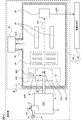
- FIG. 1 is a conceptual diagram showing the configuration of GC-MS of one embodiment.
- FIG. 2 is a conceptual diagram showing an ionization unit according to an embodiment.
- FIG. 3 is a conceptual diagram showing the sixth opening.
- FIG. 4 is a conceptual diagram showing the configuration of the ionized portion according to the modified example.
- FIG. 5 is a conceptual diagram showing the configuration of the GC-MS of the modified example.
- FIG. 6 is a conceptual diagram showing the configuration of the ionized portion according to the modified example.
- FIG. 7 is a chromatogram obtained in a comparative example.
- FIG. 8 is a chromatogram obtained in the examples.
- FIG. 1 is a conceptual diagram showing the configuration of a gas chromatograph-mass spectrometer (GC-MS) 1 of the present embodiment.
- the GC-MS1 includes a measuring unit 100 and an information processing unit 40.
- the measuring unit 100 includes a gas chromatograph (GC) 10, a sample gas introduction tube 20, and a mass spectrometer 30.
- the GC 10 includes a carrier gas flow path 11 and a sample introduction section 12.
- the mass spectrometer 30 includes a vacuum vessel 31, an exhaust port 32, a vacuum exhaust system 33, an ionization unit 300 that ionizes the sample S to generate ions In, an ion adjustment unit 34, and a mass separation unit 35. It includes a detection unit 36.
- the ionization unit 300 includes an ionization chamber 310, a filament 320, and a trap electrode 330.
- the measuring unit 100 separates and detects each component of the sample by a separation operation of two or more steps including gas chromatography and mass separation.
- the GC10 functions as a separation unit that separates the sample S introduced into the GC10 by gas chromatography.
- the carrier gas flow path 11 is a flow path for the carrier gas, and the carrier gas is introduced into the sample introduction unit 12 (arrow A1).
- the composition of the carrier gas is not particularly limited, but GC-MS1 can use at least nitrogen as the carrier gas. In the following, nitrogen refers to nitrogen molecules.
- the sample introduction unit 12 is provided with a chamber for introducing a sample such as a sample vaporization chamber, temporarily accommodates a sample injected by an injector such as a syringe or an autosampler (not shown), and vaporizes the sample when it is a liquid. Then, the sample gas is introduced into a separation column (not shown) (arrow A2).
- a separation column is attached to the GC10, and the sample S is separated in the separation column.
- the sample S is in the form of a gas or a gas, which is appropriately referred to as a sample gas.
- the type of separation column is not particularly limited, and any column such as a capillary column can be used.
- Each component of the sample gas separated in the GC 10 is eluted from the separation column at different times and introduced into the ionization unit 300 of the mass spectrometry unit 30 through the sample gas introduction tube 20.
- the sample gas introduction tube 20 may be integrated with the separation column.
- the mass spectrometer 30 includes a mass spectrometer and ionizes the sample S introduced into the ionization unit 300, separates the mass, and detects the sample S.
- the ion In derived from the sample S generated in the ionization unit 300 moves along the ion optical axis Ax1. If the ion In derived from the sample S can be mass-separated and detected with a desired accuracy, the type of the mass spectrometer constituting the mass spectrometer 30 is not particularly limited, and one or more masses of any kind are used. Those including an analyzer can be used.
- the vacuum container 31 of the mass spectrometer 30 includes an exhaust port 32.
- the exhaust port 32 is connected to the vacuum exhaust system 33 so as to be exhaustable.
- the vacuum exhaust system 33 includes a pump capable of achieving a low pressure of 10-2 Pa or less, such as a turbo molecular pump, and an auxiliary pump thereof.
- a pump capable of achieving a low pressure of 10-2 Pa or less such as a turbo molecular pump, and an auxiliary pump thereof.
- FIG. 1 the points at which the gas inside the vacuum vessel 31 is discharged are schematically indicated by arrows A10.
- the ionization unit 300 of the mass spectrometry unit 30 ionizes the sample S introduced into the ionization unit 300 by electron ionization (EI).
- EI electron ionization
- a sample gas introduction tube 20 is connected to the ionization chamber 310 so that the sample gas can be introduced into the ionization chamber.
- the sample S introduced into the ionization chamber 310 is irradiated with thermions emitted from the filament 320.
- the flow of thermions is schematically shown by an arrow A20.
- the amount of thermions to be irradiated is detected by a trap electrode 330 arranged on the opposite side of the filament 320 with the ionization chamber 310 in between.
- Ions In derived from sample S including molecular ions or fragment ions, are emitted from the ionization chamber 310 by an electromagnetic action based on a voltage applied to an electrode arranged outside the ionization chamber 310.
- a voltage having a polarity opposite to that of the ion In to be detected is applied to the ion adjusting unit 34, and the ion In is accelerated by a drawing electric field based on the voltage.
- the ion In may be accelerated by the pushing electric field based on the voltage.
- FIG. 2 is a conceptual diagram showing the configuration of the ionization unit 300.
- the ionization unit 300 includes an ionization chamber 310, a filament 320, a trap electrode 330, and magnets 340a and 340b.
- the ionization chamber 310 includes a first side wall 311, a second side wall 312, a third side wall 313, a fourth side wall 314, and a fifth side wall 315.
- the ionization chamber 310 includes a sixth side wall, which is a side wall (not shown) arranged at a position facing the fifth side wall 315.
- side wall when the term "side wall” is simply used, the first side wall 311, the second side wall 312, the third side wall 313, the fourth side wall 314, the fifth side wall 315 and the sixth side wall are referred to without distinction.
- the Z axis is set in the direction connecting the filament 320 and the trap electrode 330
- the X axis is set in the direction along the ion optical axis Ax1
- the Y axis is set perpendicular to the Z axis and the X axis.
- the first side wall 311 and the second side wall 312 are arranged along the XY plane.
- the third side wall 313 and the fourth side wall 314 are arranged along the YZ plane.
- the fifth side wall 315 and the sixth side wall are arranged along the ZX plane.
- a first opening 301 and a sixth opening 306 are formed on the first side wall 311 of the ionization chamber 310.
- a second opening 302 and a fifth opening 305 are formed on the second side wall 312.
- the second side wall 312 is formed at a position facing the first side wall 311 with the ion optical axis Ax1 interposed therebetween.
- a third opening 303 is formed in the third side wall 313.
- a fourth opening 304 is formed in the fourth side wall 314.
- the side wall of the ionization chamber 310 is made of a metal such as stainless steel.
- the thickness of the side wall of the ionization chamber 310 is not particularly limited as long as there is no problem in production and analysis, and can be, for example, several mm.
- a voltage of + several tens V to several hundreds V is applied to the filament 320 in the ionization chamber 310 including the first side wall 311. This voltage is appropriately set from the viewpoint of increasing the efficiency of ionization.
- the ionization chamber 310 can be, for example, a rectangular parallelepiped or a cylinder.
- the shape of the ionization chamber 310 is not particularly limited as long as the thermions emitted from the filament 320 can be passed through the first opening 301 to irradiate the sample S and the ions In obtained by the irradiation can be emitted from the ionization chamber. ..
- the first opening 301 is an opening through which thermions emitted from the filament 320 pass when entering the inside of the ionization chamber 310.
- the second opening 302 is an opening through which thermions emitted from the filament 320 pass when they are emitted from the ionization chamber 310.
- the first opening 301 and the second opening 302 are formed with the axis Ax2 as the central axis. It is preferable that the axis Ax2 is substantially orthogonal to the flow of the sample gas from the sample gas introduction tube 20 and the ion optical axis Ax1.
- the sample gas introduction tube 20 is arranged so that the flow of the sample S discharged from the sample gas introduction tube 20 passes through the intersection of the axis Ax2 and the ion optical axis Ax1.
- the shapes of the first opening 301 and the second opening 302 are not particularly limited as long as ionization can be performed with a desired efficiency.
- the first opening 301 and the second opening 302 can be circular, elliptical, square, or rectangular.
- the sample gas introduction pipe 20 is arranged through the third opening 303.
- the third opening 303 is an opening through which the sample gas passes from the GC 10 when it is introduced into the ionization chamber 310.
- the ion optical axis Ax1 passes through the fourth opening 304.
- the fourth opening 304 is an opening through which the sample ionized in the ionization chamber 310 passes when the sample is emitted from the ionization chamber 310.
- the fifth opening 305 is an opening through which the calibration sample is introduced into the ionization chamber 310.
- a calibration sample introduction tube 60 is arranged through the fifth opening 305.
- the calibration sample introduction tube 60 may not be arranged in the fifth opening 305, and the calibration sample may be introduced into the ionization chamber 310 by diffusion from the outside of the ionization chamber 310.
- the type of the sample for calibration is not particularly limited, but PFTBA (Perfluorotributylamine) or the like used when adjusting each part of the mass spectrometry unit 30 so as to increase the sensitivity can be used.
- the sixth opening 306 is an opening for promoting the discharge of the carrier gas from the ionization chamber 310.
- the sixth opening 306 functions as a nitrogen gas discharge port for discharging nitrogen gas. If the size of the carrier gas molecule, such as nitrogen gas, is larger than that of helium, thermions collide with the molecule and the proportion of thermions that contribute to ionization decreases, resulting in a decrease in ionization efficiency. .. This point becomes more remarkable because the molecular weight of the carrier gas, such as nitrogen gas, is larger than that of helium, and the residence time in the ionization chamber 310 is long. Ions derived from nitrogen gas may be detected as noise. For this reason, when nitrogen gas is used as the carrier gas, the sensitivity may decrease. By discharging nitrogen gas from the sixth opening 306, it is possible to suppress a decrease in sensitivity.
- FIG. 3 is a view when the sixth opening 306 is viewed from the positive side to the negative side of the Z axis in FIG. 2 in the direction perpendicular to the first side wall 311.
- the sixth opening 306 is a circular opening at the first side wall 311.
- the area S6 of the sixth opening 306 is the area of the opening in the side wall of the ionization chamber 310 in square millimeters (mm 2 ) with respect to the volume inside the ionization chamber 310 in cubic millimeters (mm 3).
- the total ratio is set to be 1/30 or more.
- the total area of the openings in the side wall of the ionization chamber 310 is the first opening 301, the second opening 302, the third opening 303, the fourth opening 304, and the fifth opening. It is the sum of the areas of 305 and the sixth opening 306.
- the area of the opening can be, for example, the minimum value of the area where the surface parallel to the side wall on which the opening is formed and the opening overlap.
- the sixth opening 306 can be formed at an arbitrary position on the side wall of the ionization chamber 310. Further, the shape of the sixth opening 306 is not particularly limited.
- the maximum diameter L6 of the sixth opening 306 is preferably less than 20 mm, more preferably 2 mm or more and less than 4 mm, further preferably 2.5 mm or more and less than 3.5 mm, and even more preferably 3 mm.
- the maximum diameter L6 of the sixth opening 306 is the length of the longest line segment among the line segments connecting two points on the inner wall of the sixth opening 306 parallel to the side wall on which the sixth opening 306 is formed. Can be.
- a plurality of sixth openings 306 may be arranged on the side wall of the ionization chamber 310.
- the lower limit of the maximum diameter L6 of the sixth opening 306 is not particularly limited, and may be, for example, 0.1 mm or more.
- the trap electrode 330 can be any electrode capable of detecting thermions, but preferably contains a filament.
- the trap electrode 330 is electrically connected to an ammeter or the like (not shown), and is configured to be able to measure the amount of thermions reaching the trap electrode 330.
- the trap electrode 330 is a filament
- the filament can be used as a thermionic source and the filament 320 can be used as a trap electrode for EI. In this case, it is more preferable that the filament 320 and the trap electrode 330 have the same shape.
- the thermions emitted from the filament 320 move along a spiral orbit by the magnetic field generated by the magnets 340a and 340b arranged in the ionization unit 300. As a result, the thermions and the sample S can easily react with each other, and the ionization efficiency is enhanced.
- the ion adjusting unit 34 of the mass spectrometry unit 30 is provided with an ion transport system such as an ion guide, and adjusts by converging the flux of ions In by an electromagnetic action.
- the ion In emitted from the ion adjusting unit 34 is introduced into the mass separating unit 35.
- the mass separation unit 35 of the mass spectrometry unit 30 includes a quadrupole mass filter and mass-separates the introduced ion In.
- the mass separation unit 35 selectively passes the ion In based on the value of the mass-to-charge ratio by the voltage applied to the quadrupole mass filter.
- the ion In obtained by the mass separation of the mass separation unit 35 is incident on the detection unit 36.
- the detection unit 36 of the mass spectrometry unit 30 includes an ion detector and detects the incident ion In.
- the detection unit 36 A / D -converts the detection signal obtained by detecting the incident ion In by an analog / digital (A / D) converter (not shown), and converts the digitized detection signal into digital. Output to the information processing unit 40 (arrow A20).
- the data based on the detection signal obtained by the detection unit 36 detecting the ion In is referred to as measurement data.
- the information processing unit 40 is provided with an information processing device such as a computer, serves as an interface with a GC-MS1 user (hereinafter, simply referred to as a "user"), and processes communication, storage, calculation, and the like related to various data. I do.
- the information processing unit 40 acquires information on analysis conditions and the like from the user via an input device such as a mouse, keyboard, or touch panel.
- the information processing unit 40 includes a processing device such as a CPU (Central Processing Unit) and a control unit including a storage medium such as a memory and a hard disk.
- the processing device reads a program stored in a hard disk or the like into a memory and executes the program, controls the measurement unit 100, processes measurement data, and is the main operation of the GC-MS1.
- the method of processing the measurement data is not particularly limited, and data corresponding to the chromatogram in which the retention time of the ion In detected by the detection unit 36 and the intensity of the detection signal are associated with each other can be created, or the molecule contained in the sample S can be produced. Can be identified or quantified.
- the information processing unit 40 includes a display device such as a display monitor, and displays information obtained by processing by the processing device.
- the measuring unit 100 and the information processing unit 40 may be configured as an integrated device.
- the ratio of the total area of the openings in the side walls of the ionization chamber in square millimeters to the volume inside the ionization chamber 310 in cubic millimeters is 30 minutes. 1 or more.
- the mass spectrometer 1 of the present embodiment includes a sixth opening 306 in addition to the first to fifth openings. The sixth opening 306 can be easily processed, and the mass spectrometer 1 in which the decrease in sensitivity is suppressed can be realized.
- the sixth opening 306 is formed on the side wall of the ionization chamber 310.
- the sixth opening may not be formed in the ionization chamber, and at least one area of the first opening, the second opening, the third opening, the fourth opening, and the fifth opening may be expanded. ..
- FIG. 4 is a conceptual diagram showing the configuration of the ionization unit 300a of this modified example.
- the ionization unit 300a is different from the above-mentioned ionization unit 300 in that the ionization chamber 310a is provided instead of the ionization chamber 310.
- the ionization chamber 310a is not provided with the sixth opening 306, is provided with the first side wall 311a instead of the first side wall 311 and is provided with the first opening 301a instead of the first opening 301. Is different.
- the first opening 301a is a circular, elliptical, square, or rectangular opening when viewed from a direction perpendicular to the first side wall 311a.
- the area of the first opening 301a is the total area of the openings on the side walls of the ionization chamber 310a in square millimeters (mm 2 ) with respect to the volume inside the ionization chamber 310a in cubic millimeters (mm 3).
- the ratio of is set to be 1/30 or more. Even with the GC-MS of this modification, it is possible to suppress a decrease in sensitivity when nitrogen gas is used as the carrier gas.
- the size of the second opening 302 is the same as that of the first opening 301a. .. Further, the ratio of the total area of the openings in the side wall of the ionization chamber 310a having the unit of square millimeters (mm 2 ) to the volume inside the ionization chamber 310a having the unit of cubic millimeters (mm 3) is 30 minutes. If it becomes 1 or more, the size of any 1 or more openings may be changed. In addition to changing the size of the first opening 301a as in this modification, the size of at least one of the second opening 302, the third opening 303, the fourth opening 304, and the fifth opening 305 is changed. You may.
- the area of the opening formed on the side wall of the ionization chamber may be controllably controlled.
- FIG. 5 is a conceptual diagram showing the configuration of GC-MS of this modified example.
- the GC-MS1 includes a measuring unit 100a and an information processing unit 40a.
- the measuring unit 100a is different from the above-mentioned measuring unit 100 in that the ionizing unit 300b is provided instead of the ionizing unit 300.
- the ionization unit 300b is different from the above-mentioned ionization unit 300 in that the ionization chamber 310b is provided instead of the ionization chamber 310.
- the information processing unit 40a is different from the above-mentioned information processing unit 400 in that the opening control unit 400 is provided.
- FIG. 6 is a conceptual diagram showing the configuration of the ionization unit 300b.
- the ionization chamber 310b is different from the above-mentioned ionization chamber 310 in that the first side wall 311b in which the opening / closing mechanism 360 is installed is provided instead of the first side wall 311.
- the opening / closing mechanism 360 is configured as an actuator and includes a lid 360a and a driving device 360b.
- the opening / closing mechanism 360 functions as an opening / closing portion for opening / closing the sixth opening 306.
- the opening / closing mechanism is controlled by the opening control unit 400 (FIG. 5).
- the opening control unit 400 is included in the control unit of the information processing unit 40a.
- the opening control unit 400 sends a control signal to the opening / closing mechanism 360.
- the drive device 360b opens and closes the sixth opening 306 by moving the lid 360a.
- the configuration of the opening / closing mechanism 360 is not particularly limited as long as the area of the sixth opening 306 can be changed. Further, at least one of the openings formed in the ionization chamber 310b can be configured to control its area in a changeable manner. An opening / closing mechanism is installed for at least one of the first opening 301, the second opening 302, the third opening 303, the fourth opening 304, the fifth opening 305, and the sixth opening 306. The area can be changed.
- the gas chromatograph mass spectrometer is a gas chromatograph mass spectrometer including a separation unit for separating a sample and a mass spectrometer for mass spectrometry of the sample introduced from the separation unit.
- the mass spectrometer is provided with a filament and an ionization chamber into which the thermions from the filament and the sample from the separation unit are introduced, and the inside of the ionization chamber is in cubic millimeters (mm 3).
- the ratio of the total area (mm 2 ) of the opening in the side wall of the ionization chamber in square millimeters to the volume of is 1/30 or more. This makes it possible to suppress a decrease in analysis sensitivity when a gas containing a molecule or atom having a molecular weight larger than that of helium, such as nitrogen gas, is used as the carrier gas.
- thermions from the filament are placed on the side wall of the ionization chamber in the ionization chamber.
- the fourth opening through which the ionized sample passes when exiting the ionization chamber, and the fifth opening through which the ionized sample passes when introduced at least one sixth.
- An opening can be formed. As a result, it is possible to easily process an ionization chamber capable of suppressing a decrease in analysis sensitivity.
- the maximum diameter of the sixth opening can be less than 20 mm.
- the gas chromatograph mass spectrometer according to the second or third aspect may include an opening / closing portion for opening / closing the sixth opening. This makes it possible to perform analysis under conditions suitable for each of the carrier gases having different molecular weights.
- the opening of the opening formed in the ionization chamber in the gas chromatograph mass spectrometer according to any one of items 1 to 3, can be provided. This makes it possible to perform analysis under conditions more suitable for each of the carrier gases having different molecular weights.
- the ionization chamber is capable of electron impact ionization. Yes, nitrogen gas can be used as the carrier gas. This makes it possible to more reliably suppress the decrease in analysis sensitivity.
- the present invention is not limited to the contents of the above embodiment. Other aspects conceivable within the scope of the technical idea of the present invention are also included within the scope of the present invention.
- FIG. 7 is a diagram showing a chromatogram obtained in this comparative example.
- the chromatogram is a graph showing the retention time on the horizontal axis and the intensity of the detection signal in the mass spectrometry of the sample eluted during the retention time on the vertical axis.
- the peak P1 is a peak corresponding to octafluoronaphthalene.
- the signal-to-noise ratio (Signal / Noise ratio; S / N ratio) calculated by quantifying noise by the root mean square (RMS) method using the peak corresponding to octafluoronaphthalene was 78.18.
- FIG. 8 is a diagram showing a chromatogram obtained in this example.
- the peak P2 is a peak corresponding to octafluoronaphthalene.
- the S / N ratio was 693.34.
Landscapes
- Chemical & Material Sciences (AREA)
- Chemical Kinetics & Catalysis (AREA)
- Electrochemistry (AREA)
- Physics & Mathematics (AREA)
- Health & Medical Sciences (AREA)
- Life Sciences & Earth Sciences (AREA)
- Analytical Chemistry (AREA)
- Biochemistry (AREA)
- General Health & Medical Sciences (AREA)
- General Physics & Mathematics (AREA)
- Immunology (AREA)
- Pathology (AREA)
- Other Investigation Or Analysis Of Materials By Electrical Means (AREA)
Priority Applications (2)
| Application Number | Priority Date | Filing Date | Title |
|---|---|---|---|
| PCT/JP2020/018600 WO2021224973A1 (ja) | 2020-05-08 | 2020-05-08 | ガスクロマトグラフ質量分析計 |
| JP2022519866A JP7409492B2 (ja) | 2020-05-08 | 2020-05-08 | ガスクロマトグラフ質量分析計 |
Applications Claiming Priority (1)
| Application Number | Priority Date | Filing Date | Title |
|---|---|---|---|
| PCT/JP2020/018600 WO2021224973A1 (ja) | 2020-05-08 | 2020-05-08 | ガスクロマトグラフ質量分析計 |
Publications (1)
| Publication Number | Publication Date |
|---|---|
| WO2021224973A1 true WO2021224973A1 (ja) | 2021-11-11 |
Family
ID=78467986
Family Applications (1)
| Application Number | Title | Priority Date | Filing Date |
|---|---|---|---|
| PCT/JP2020/018600 Ceased WO2021224973A1 (ja) | 2020-05-08 | 2020-05-08 | ガスクロマトグラフ質量分析計 |
Country Status (2)
| Country | Link |
|---|---|
| JP (1) | JP7409492B2 (https=) |
| WO (1) | WO2021224973A1 (https=) |
Citations (6)
| Publication number | Priority date | Publication date | Assignee | Title |
|---|---|---|---|---|
| JPH11344472A (ja) * | 1998-04-30 | 1999-12-14 | Hewlett Packard Co <Hp> | イオン化検出器における検体拡散の抑制方法とその装置 |
| JP2001126658A (ja) * | 1999-10-29 | 2001-05-11 | Jeol Ltd | 質量分析装置 |
| JP2003270207A (ja) * | 2002-03-12 | 2003-09-25 | Jeol Ltd | 質量分析装置用イオン化装置および質量分析装置 |
| WO2007102204A1 (ja) * | 2006-03-07 | 2007-09-13 | Shimadzu Corporation | 質量分析装置 |
| CN107301945A (zh) * | 2016-04-14 | 2017-10-27 | 广州禾信仪器股份有限公司 | 电子轰击源及质谱仪 |
| WO2018100621A1 (ja) * | 2016-11-29 | 2018-06-07 | 株式会社島津製作所 | イオン化装置及び質量分析装置 |
Family Cites Families (4)
| Publication number | Priority date | Publication date | Assignee | Title |
|---|---|---|---|---|
| JPS6015247Y2 (ja) * | 1980-04-28 | 1985-05-14 | 株式会社島津製作所 | 質量分析用イオン源装置 |
| WO2008037073A1 (en) * | 2006-09-25 | 2008-04-03 | Mds Analytical Technologies, A Business Unit Of Mds Inc., Doing Business Through Its Sciex Division | Multiple sample sources for use with mass spectrometers, and apparatus, devices, and methods therefor |
| US8426805B2 (en) * | 2008-02-05 | 2013-04-23 | Thermo Finnigan Llc | Method and apparatus for response and tune locking of a mass spectrometer |
| US9048080B2 (en) * | 2010-08-19 | 2015-06-02 | Leco Corporation | Time-of-flight mass spectrometer with accumulating electron impact ion source |
-
2020
- 2020-05-08 WO PCT/JP2020/018600 patent/WO2021224973A1/ja not_active Ceased
- 2020-05-08 JP JP2022519866A patent/JP7409492B2/ja active Active
Patent Citations (6)
| Publication number | Priority date | Publication date | Assignee | Title |
|---|---|---|---|---|
| JPH11344472A (ja) * | 1998-04-30 | 1999-12-14 | Hewlett Packard Co <Hp> | イオン化検出器における検体拡散の抑制方法とその装置 |
| JP2001126658A (ja) * | 1999-10-29 | 2001-05-11 | Jeol Ltd | 質量分析装置 |
| JP2003270207A (ja) * | 2002-03-12 | 2003-09-25 | Jeol Ltd | 質量分析装置用イオン化装置および質量分析装置 |
| WO2007102204A1 (ja) * | 2006-03-07 | 2007-09-13 | Shimadzu Corporation | 質量分析装置 |
| CN107301945A (zh) * | 2016-04-14 | 2017-10-27 | 广州禾信仪器股份有限公司 | 电子轰击源及质谱仪 |
| WO2018100621A1 (ja) * | 2016-11-29 | 2018-06-07 | 株式会社島津製作所 | イオン化装置及び質量分析装置 |
Also Published As
| Publication number | Publication date |
|---|---|
| JPWO2021224973A1 (https=) | 2021-11-11 |
| JP7409492B2 (ja) | 2024-01-09 |
Similar Documents
| Publication | Publication Date | Title |
|---|---|---|
| JP5268634B2 (ja) | 電子衝撃イオン源におけるイオン不安定性の制御方法及びイオン化装置 | |
| Gushenets et al. | Simple and inexpensive time-of-flight charge-to-mass analyzer for ion beam source characterization | |
| JP5324457B2 (ja) | 静電型イオントラップ | |
| US8344317B2 (en) | Molecular ion accelerator | |
| CN101281165A (zh) | 一种质谱分析样品的离子化方法及其装置 | |
| Maeda et al. | A two-stage double-hemispherical electron energy selector | |
| US6633041B2 (en) | Method for analyzing the mass of a sample using a cold cathode ionization source mass filter | |
| US20120286150A1 (en) | Method and apparatus for transmitting ions in a mass spectrometer maintained in a sub-atmospheric pressure regime | |
| US11875982B2 (en) | Multi-modal ionization for mass spectrometry | |
| JP2009129868A (ja) | 質量分析装置及びその調整方法 | |
| WO2017033959A1 (ja) | 大気圧イオン化方法 | |
| JP6594983B2 (ja) | イオンビーム装置、及び試料元素分析方法 | |
| JPWO2013001604A1 (ja) | 三連四重極型質量分析装置 | |
| Thiel et al. | Two-stage gas amplifier for ultrahigh resolution low vacuum scanning electron microscopy | |
| JP5142273B2 (ja) | 中性粒子質量分析装置及び分析方法 | |
| WO2021224973A1 (ja) | ガスクロマトグラフ質量分析計 | |
| JP3018880B2 (ja) | 質量分析装置及び質量分析方法 | |
| US20170347443A1 (en) | Ion Throughput Pump and Method | |
| Hanson et al. | Selective background suppression in MALDI-TOF mass spectrometry | |
| US11482405B2 (en) | Mass spectrometry device and mass spectrometry method | |
| US20220317089A1 (en) | Gas chromatograph mass spectrometer and mass spectrometry method | |
| CN116206943B (zh) | 质谱仪及其气相离子源装置 | |
| Kalinin et al. | Ion source with longitudinal ionization of a molecular beam by an electron beam in a magnetic field | |
| CN108226276B (zh) | 一种乙二醛和/或甲基乙二醛的无碎裂质谱检测方法 | |
| Brinkmalm et al. | DIPLOMA: An experimental system to study MeV and keV particle‐and photon‐induced desorption of molecules |
Legal Events
| Date | Code | Title | Description |
|---|---|---|---|
| 121 | Ep: the epo has been informed by wipo that ep was designated in this application |
Ref document number: 20934274 Country of ref document: EP Kind code of ref document: A1 |
|
| ENP | Entry into the national phase |
Ref document number: 2022519866 Country of ref document: JP Kind code of ref document: A |
|
| NENP | Non-entry into the national phase |
Ref country code: DE |
|
| 122 | Ep: pct application non-entry in european phase |
Ref document number: 20934274 Country of ref document: EP Kind code of ref document: A1 |