WO2021220798A1 - 電子機器、電子機器の制御方法、プログラム - Google Patents
電子機器、電子機器の制御方法、プログラム Download PDFInfo
- Publication number
- WO2021220798A1 WO2021220798A1 PCT/JP2021/015327 JP2021015327W WO2021220798A1 WO 2021220798 A1 WO2021220798 A1 WO 2021220798A1 JP 2021015327 W JP2021015327 W JP 2021015327W WO 2021220798 A1 WO2021220798 A1 WO 2021220798A1
- Authority
- WO
- WIPO (PCT)
- Prior art keywords
- user
- electronic device
- line
- sight
- light
- Prior art date
- Legal status (The legal status is an assumption and is not a legal conclusion. Google has not performed a legal analysis and makes no representation as to the accuracy of the status listed.)
- Ceased
Links
Images

Classifications
-
- H—ELECTRICITY
- H04—ELECTRIC COMMUNICATION TECHNIQUE
- H04N—PICTORIAL COMMUNICATION, e.g. TELEVISION
- H04N23/00—Cameras or camera modules comprising electronic image sensors; Control thereof
- H04N23/60—Control of cameras or camera modules
- H04N23/61—Control of cameras or camera modules based on recognised objects
- H04N23/611—Control of cameras or camera modules based on recognised objects where the recognised objects include parts of the human body
-
- G—PHYSICS
- G06—COMPUTING OR CALCULATING; COUNTING
- G06V—IMAGE OR VIDEO RECOGNITION OR UNDERSTANDING
- G06V40/00—Recognition of biometric, human-related or animal-related patterns in image or video data
- G06V40/10—Human or animal bodies, e.g. vehicle occupants or pedestrians; Body parts, e.g. hands
- G06V40/18—Eye characteristics, e.g. of the iris
-
- A—HUMAN NECESSITIES
- A61—MEDICAL OR VETERINARY SCIENCE; HYGIENE
- A61B—DIAGNOSIS; SURGERY; IDENTIFICATION
- A61B5/00—Measuring for diagnostic purposes; Identification of persons
- A61B5/117—Identification of persons
- A61B5/1171—Identification of persons based on the shapes or appearances of their bodies or parts thereof
-
- G—PHYSICS
- G06—COMPUTING OR CALCULATING; COUNTING
- G06F—ELECTRIC DIGITAL DATA PROCESSING
- G06F21/00—Security arrangements for protecting computers, components thereof, programs or data against unauthorised activity
- G06F21/30—Authentication, i.e. establishing the identity or authorisation of security principals
- G06F21/31—User authentication
- G06F21/32—User authentication using biometric data, e.g. fingerprints, iris scans or voiceprints
-
- G—PHYSICS
- G06—COMPUTING OR CALCULATING; COUNTING
- G06F—ELECTRIC DIGITAL DATA PROCESSING
- G06F3/00—Input arrangements for transferring data to be processed into a form capable of being handled by the computer; Output arrangements for transferring data from processing unit to output unit, e.g. interface arrangements
- G06F3/01—Input arrangements or combined input and output arrangements for interaction between user and computer
- G06F3/03—Arrangements for converting the position or the displacement of a member into a coded form
- G06F3/033—Pointing devices displaced or positioned by the user, e.g. mice, trackballs, pens or joysticks; Accessories therefor
- G06F3/0346—Pointing devices displaced or positioned by the user, e.g. mice, trackballs, pens or joysticks; Accessories therefor with detection of the device orientation or free movement in a 3D space, e.g. 3D mice, 6-DOF [six degrees of freedom] pointers using gyroscopes, accelerometers or tilt-sensors
-
- G—PHYSICS
- G06—COMPUTING OR CALCULATING; COUNTING
- G06V—IMAGE OR VIDEO RECOGNITION OR UNDERSTANDING
- G06V10/00—Arrangements for image or video recognition or understanding
- G06V10/10—Image acquisition
- G06V10/12—Details of acquisition arrangements; Constructional details thereof
- G06V10/14—Optical characteristics of the device performing the acquisition or on the illumination arrangements
- G06V10/143—Sensing or illuminating at different wavelengths
-
- G—PHYSICS
- G06—COMPUTING OR CALCULATING; COUNTING
- G06V—IMAGE OR VIDEO RECOGNITION OR UNDERSTANDING
- G06V40/00—Recognition of biometric, human-related or animal-related patterns in image or video data
- G06V40/60—Static or dynamic means for assisting the user to position a body part for biometric acquisition
-
- G—PHYSICS
- G06—COMPUTING OR CALCULATING; COUNTING
- G06V—IMAGE OR VIDEO RECOGNITION OR UNDERSTANDING
- G06V40/00—Recognition of biometric, human-related or animal-related patterns in image or video data
- G06V40/70—Multimodal biometrics, e.g. combining information from different biometric modalities
-
- H—ELECTRICITY
- H04—ELECTRIC COMMUNICATION TECHNIQUE
- H04N—PICTORIAL COMMUNICATION, e.g. TELEVISION
- H04N23/00—Cameras or camera modules comprising electronic image sensors; Control thereof
- H04N23/50—Constructional details
- H04N23/53—Constructional details of electronic viewfinders, e.g. rotatable or detachable
-
- H—ELECTRICITY
- H04—ELECTRIC COMMUNICATION TECHNIQUE
- H04N—PICTORIAL COMMUNICATION, e.g. TELEVISION
- H04N23/00—Cameras or camera modules comprising electronic image sensors; Control thereof
- H04N23/56—Cameras or camera modules comprising electronic image sensors; Control thereof provided with illuminating means
-
- H—ELECTRICITY
- H04—ELECTRIC COMMUNICATION TECHNIQUE
- H04N—PICTORIAL COMMUNICATION, e.g. TELEVISION
- H04N23/00—Cameras or camera modules comprising electronic image sensors; Control thereof
- H04N23/60—Control of cameras or camera modules
-
- H—ELECTRICITY
- H04—ELECTRIC COMMUNICATION TECHNIQUE
- H04N—PICTORIAL COMMUNICATION, e.g. TELEVISION
- H04N5/00—Details of television systems
- H04N5/76—Television signal recording
- H04N5/765—Interface circuits between an apparatus for recording and another apparatus
- H04N5/77—Interface circuits between an apparatus for recording and another apparatus between a recording apparatus and a television camera
Definitions
- the present invention relates to an electronic device, a control method for the electronic device, and a program.
- Electronic devices include line-of-sight input technology, which is a technology that accepts line-of-sight input.
- Patent Document 1 describes a video camera that detects a viewpoint position (a position viewed by a user).
- biometric authentication includes a technique in which an electronic device identifies (authenticates) an individual user.
- Patent Document 2 describes an iris authentication technique for identifying an individual user using an iris.
- the radius of gyration of the eyeball and the line-of-sight deviation when the pupil is opened and closed differ for each user.
- Feature data is needed.
- an object of the present invention is to reduce the complexity when a plurality of people use the line-of-sight input.
- control means for controlling the user's line-of-sight feature data to be recorded in the recording means, the authentication means for authenticating the user, and the line-of-sight feature data for the authenticated user are recorded.
- the electronic device is characterized by having a detection means for detecting the line of sight of the user by using the feature data of the line of sight recorded.
- control step of controlling the user's line-of-sight feature data to be recorded in the recording means, the authentication step of authenticating the user, and the line-of-sight feature data of the authenticated user are recorded.
- the means it is a control method of an electronic device characterized by having a detection step of detecting the line of sight of the user by using the feature data of the line of sight recorded.
- FIG. 1 is a configuration diagram of an image pickup apparatus according to the first embodiment.
- FIG. 2 is a diagram illustrating recording of calibration data and the like according to the first embodiment.
- FIG. 3 is a diagram illustrating reading of calibration data according to the first embodiment.
- FIG. 4 is a flowchart for setting the calibration data according to the first embodiment.
- FIG. 5 is a diagram illustrating reading of calibration data according to the second embodiment.
- FIG. 6 is a diagram illustrating recording of calibration data and the like according to the third embodiment.
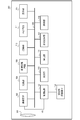
- FIG. 1 is a configuration diagram of an image pickup apparatus 100 according to the first embodiment.
- the imaging device 100 is not limited to a camera such as a digital camera, but may be another electronic device such as a smartphone or a personal computer as long as it can accept the user's line-of-sight input.
- the image pickup device 100 includes a lens unit 101, an image pickup element 102, a light source section 103, an image processing circuit 109, a recording section 110, a memory circuit 111, a control circuit 112, a display section 113, a detection section 114, and an iris recognition section 115. Further, the image pickup device 100 includes an operation unit 116, a display unit 117, a line-of-sight image sensor 118, and a bus 120.
- the lens unit 101 collects the incident light from the subject on the image sensor 102.
- the lens unit 101 has, for example, a plurality of lenses, an aperture, and the like.
- the image sensor 102 acquires an image (image data) of the subject based on the light collected by the lens unit 101.
- the light source unit 103 has a light source that irradiates the subject with light.
- the image processing circuit 109 (development processing unit) performs development processing such as color matrix processing and gamma processing on the image acquired from the image sensor 102. In these processes, the image processing circuit 109 records an image in the memory circuit 111 as needed. Then, the image processing circuit 109 outputs the processed image to the display unit 113, the display unit 117, and the recording unit 110.
- the recording unit 110 records (stores) images, programs, and the like.
- the recording unit 110 records iris data indicating the characteristics of the iris and calibration data associated with the iris data for each user.
- the calibration data is the characteristic data of the line of sight used for specifying the position of the viewpoint (viewpoint position) by correcting the radius of gyration of the eyeball and the deviation of the line of sight when the pupil is opened and closed for each user. Is. That is, the calibration data is information that links the direction of the user's eyes with the position (viewpoint position) actually viewed by the user.
- the control circuit 112 executes image processing of the image processing circuit 109 and some control of driving the image sensor 102. Further, the control circuit 112 executes display control of the display unit 113 and the display unit 117, control of receiving an instruction from the operation unit 116, and control of data transfer to the memory circuit 111 and the recording unit 110.
- the control circuit 112 does not limit the control of the image sensor 102 or the image processing circuit 109, and the image sensor 102 or the image processing circuit 109 itself may have a control unit.
- the display unit 113 and the display unit 117 display the processed image.
- the display unit 117 is an EVF (electrical viewfinder) in the present embodiment.
- the user can visually recognize the image displayed on the display unit 117 inside the image pickup apparatus 100 through the eyepiece finder (not shown). That is, the display unit 113 is a display unit that is visually recognized when the user is not in contact with (close to) the eyepiece finder.
- the display unit 117 is a display unit that is visually recognized when the user is in contact with the eyepiece finder (when looking into the eyepiece finder).
- the detection unit 114 detects the user's line of sight (viewpoint position; viewing position; line of sight position) based on the image of the user's eyes (eye movements).
- the user's line of sight (viewpoint position) is detected while the user looks into the display unit 117 through the eyepiece finder.
- the detection unit 114 acquires calibration data for each user.
- the user can operate each functional unit of the image pickup apparatus 100 according to the viewpoint position. For example, when the viewpoint position on the display unit 117 is detected, the image pickup apparatus 100 can execute AF (autofocus) on the detected position.
- the detection unit 114 detects the user's viewpoint position based on the image of the user's eyes acquired from the line-of-sight image sensor 118.
- the iris authentication unit 115 acquires iris data, which is user-specific information (biometric authentication data), authenticates the user (with iris authentication), and links the calibration data and the iris data (individual user). ..
- the operation unit 116 generates an operation signal according to the user operation.
- the operation unit 116 includes a touch panel, a dial, four-way keys, a shutter button, a power switch, a menu button, a play button, and the like.
- the line-of-sight image sensor 118 is an image to be used for detecting the user's line-of-sight, and acquires an image obtained by capturing the image of the user's eyes.
- the line-of-sight image sensor 118 includes IR pixels having sensitivity to infrared light.
- the bus 120 is a common route for each functional unit in the image pickup apparatus 100 to exchange data with each other.
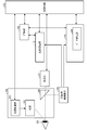
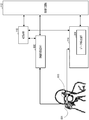
- FIG. 2 shows a functional unit that executes processing related to the flow of acquisition / recording of calibration data in the image pickup apparatus 100.
- the light source unit 103 includes a light source 201, a light source control unit 202, and a prism 205.
- the light source 201 irradiates infrared light (IR light).
- the light source control unit 202 controls the light source 201 to irradiate the user's eyes 200 with light.
- the prism 205 is arranged in front of the display unit 117, refracts the light emitted from the user's eyes 200, and causes the light to be incident on the line-of-sight image sensor 118.
- the light source control unit 202 controls the light source 201 to irradiate the user's eyes 200 with infrared light from the light source 201. Then, the infrared light reflected by the user's eyes 200 is refracted by the prism 205 and incident on the line-of-sight image sensor 118. Since the line-of-sight image sensor 118 has sensitivity to infrared light, it is possible to acquire an image obtained by capturing an image of the user's eyes 200.
- the data detection unit 204 included in the detection unit 114 responds to the image of the eyes 200 acquired by the line-of-sight image pickup element 118 when the calibration data of the user authenticated by the iris recognition unit 115 is not recorded in the recording unit 110. , Get the calibration data. If the calibration data is acquired in advance, the detection unit 114 is the position (viewpoint position) that the user is looking at on the display unit 117 according to the image of the user's eyes 200 acquired by the line-of-sight image sensor 118. Can be detected.
- the iris recognition unit 115 acquires iris data from the line-of-sight image sensor 118 based on the image when the image pickup device 100 is activated. Since the pattern of the iris portion differs from person to person, it is possible to identify an individual by treating the information obtained by quantifying the feature amount of the pattern as iris data. Then, the iris authentication unit 115 records the iris data and the calibration data in the recording unit 110 in association with each other (association). If the recording unit 110 does not record the calibration data for associating with the iris data, the data detection unit 204 acquires the calibration data (executes the calibration) as described above.
- the iris recognition unit 115 can detect an eyepiece (myopia) indicating that an image is acquired from the line-of-sight image sensor 118 or that the user has looked into the EVF, which is the display unit 117, not only at the time of activation.
- the iris pattern may be detected when (shown) is detected.
- the eyepiece detection can be performed based on, for example, a change in the amount of infrared light reflected by the object received by the eyepiece detection unit when the eyepiece detection unit irradiates the object with infrared rays.
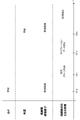
- FIG. 3 is a diagram showing a sequence of reading calibration data with respect to the passage of time (timing T310 to T313). Along with the processing of the light source 201 and the line-of-sight image sensor 118, the processing for line-of-sight detection by the iris recognition unit 115, the detection unit 114, and the like is shown.
- the light source 201 irradiates the user's eyes with light (normal irradiation), and the line-of-sight image sensor 118 acquires an image of the user's eyes.
- the light source 201 may increase the amount of light output of the emitted light. That is, in the iris recognition and the line-of-sight detection, light of different light amounts may be emitted from the light source 201.
- the iris recognition unit 115 acquires (extracts) an iris pattern from the acquired eye image.
- the control circuit 112 is recorded in the recording unit 110 in association with the iris data. Get calibration data.
- the control circuit 112 sets (determines) the acquired calibration data as data used for line-of-sight detection.
- the detection unit 114 acquires the user's viewpoint position from the image acquired for line-of-sight detection based on the set calibration data (detects the user's line of sight).
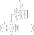
- FIG. 4 is a flowchart showing a calibration data setting process.
- the processing of this flowchart starts when the power switch is turned on and the image pickup apparatus 100 is activated.
- the processing of this flowchart is realized by the control circuit 112 reading and executing the program stored in the recording unit 110 (storage medium).
- control circuit 112 controls the iris authentication unit 115 to detect the user's iris pattern.
- the control circuit 112 determines whether or not the iris data (iris pattern data) matching the iris pattern detected in S401 is recorded in the recording unit 110. If the matching iris pattern detected in S401 is recorded, the process proceeds to S403, and if not, the process proceeds to S404. That is, in S402, the user is identified by the iris pattern (iris recognition), and it is determined whether or not the user has performed calibration in the past and has the recording unit 110 record the calibration data.
- the control circuit 112 sets the calibration data recorded in the recording unit 110 in association with the detected iris pattern as the data to be used for the line-of-sight detection. That is, in the present embodiment, in S402 and S403, the control circuit 112 performs iris authentication, and the calibration data recorded in the recording unit 110 in association with the iris-authenticated user is used as the data used for the line-of-sight detection. It is set.
- the control circuit 112 displays a selection screen for whether or not to calibrate on the display unit 117. After that, the control circuit 112 determines whether or not the user who has confirmed the selection screen has requested (instructed) calibration. If the user requests calibration, the process proceeds to S405, otherwise the process proceeds to S407. Regardless of whether or not the calibration is performed, the user may uniformly proceed to S405, or may uniformly proceed to S407.
- control circuit 112 controls the detection unit 114 (data detection unit 204) to newly acquire calibration data (executes calibration).
- control circuit 112 sets (reflects) the calibration data acquired in S405 as data used for line-of-sight detection. Further, the control circuit 112 records (saves) the iris data acquired in S401 and the calibration data acquired in S405 in association with each other in the recording unit 110. As a result, the user can use the calibration data acquired in S405 from the next time onward.
- the control circuit 112 sets standard data, which is general calibration data set in advance, as data for use in line-of-sight detection.
- the standard data can be the average data of the calibration data of a general person (plurality of people).
- the standard data may be set at the time of shipment from the factory of the image pickup apparatus 100, or may be set in advance by the user.
- the recording unit 110 records in advance a plurality of standard data prepared for each gender, age, race, and height, and in S407, the user can select data to be used for line-of-sight detection from the plurality of standard data. May be good.
- the imaging device executes iris authentication (personal authentication) and the calibration data associated with the user who has performed the iris authentication is recorded in the recording unit, the calibration is performed.
- the data is used to detect the line of sight of the user. That is, if the user has used the imaging device once, the user is identified by acquiring the iris data at startup, so that the calibration data of the user recorded by the imaging device can be used smoothly. Can be done. Further, even a user who has never used the imaging device can easily record (register) the user and the calibration data in association with each other by the iris data acquired at the time of startup. Therefore, even when a plurality of people use the image pickup device, the function corresponding to the line-of-sight input can be smoothly used.
- the light source irradiates infrared light for line-of-sight detection and acquisition of iris data
- infrared light is used for line-of-sight detection and visible for acquisition of iris data.
- Light RGB
- the configuration of the image pickup apparatus 100 according to the second embodiment is the same as the configuration of the image pickup apparatus 100 according to the first embodiment as shown in FIGS. 1 and 2. In the following, only the parts different from the first embodiment will be described, and the description of the same parts will be omitted.
- the visible light is light having a wavelength that can be seen by the human eye, and is, for example, light having a wavelength from 0.3 ⁇ m to 0.7 ⁇ m.
- the infrared light is light having a wavelength longer than that of the red color of visible light and cannot be seen by the human eye, and is, for example, light having a wavelength from 0.7 ⁇ m to 1 mm.
- the line-of-sight image sensor 118 includes RGB pixels having sensitivity to visible light (RGB) in addition to IR pixels having sensitivity to infrared light.
- the display unit 117 also operates as a light source for visible light.
- the line-of-sight image sensor 118 receives the infrared light reflected from the light source 201 by the IR pixels and outputs it as an image to the detection unit 114.
- the line-of-sight image pickup element 118 receives the reflected light of visible light from the display unit 117, which is an EVF, with RGB pixels and outputs it as an image to the iris recognition unit 115.
- FIG. 5 is a diagram showing a sequence of reading calibration data according to the second embodiment.
- the processing at the timing T510 is executed.
- the display unit 117 irradiates visible light to acquire the reflected light of the visible light in the user's eyes, so that the line-of-sight image pickup element 118 uses an RGB image as an image of the user's eyes. get.
- the processing after the timing T311 after this is the same as the processing according to the first embodiment.
- the line-of-sight detection image sensor has acquired both the image for line-of-sight detection and the image for iris recognition.
- the first image sensor acquires an image for line-of-sight detection (receives infrared light)
- the second image sensor different from the first image sensor is for iris recognition. It may be configured to acquire an image (receive visible light).
- the configuration including two light sources for line-of-sight detection and iris recognition has been described, but line-of-sight detection and iris recognition may be performed by one light source.
- a light source capable of emitting both infrared light and visible light may be adopted, and the irradiation timing may be switched between iris recognition and line-of-sight detection to irradiate the light.
- the second embodiment when acquiring the iris data, light having a wavelength different from the light for detecting the line of sight was used.
- the light used for imaging By differentiating the light used for imaging in this way, it is possible to easily change the resolution and exposure conditions at the time of imaging by line-of-sight detection and iris recognition, so the optimum conditions are set according to each application. can do.
- the present embodiment since it becomes easy to separate the functional unit for detecting the line of sight and the functional unit for iris recognition, the present embodiment can be applied to various devices.
- the image pickup apparatus 100 identifies the user (personal authentication; identification) by fingerprint authentication instead of iris authentication.
- fingerprint authentication instead of iris authentication.
- the imaging device 100 has a fingerprint authentication unit 600 instead of the iris authentication unit 115 in the configuration of the imaging device 100 according to the first embodiment.
- the light source unit 103, the line-of-sight image sensor 118, and the display unit 117 shown in FIG. 2 are collectively shown as the line-of-sight detection block 610.
- the fingerprint detection unit 601 detects the user's fingerprint pattern and the fingerprint authentication unit 600 fingerprints. Acquire data and perform fingerprint authentication. Further, the recording unit 110 records the fingerprint data and the calibration data in association with each other.
- the control circuit 112 controls the fingerprint detection unit 601 to detect the fingerprint pattern of the user, and controls the fingerprint authentication unit 600 to acquire fingerprint data. Then, when the fingerprint data matching the acquired fingerprint data is recorded in the recording unit 110, the control circuit 112 uses the calibration data recorded in association with the acquired fingerprint data for line-of-sight detection. Set as the data to be used. By performing such a process, the same effect as that of the first embodiment can be obtained even when personal authentication is performed using a fingerprint.
- any personal authentication may be used instead of iris authentication or fingerprint authentication.
- face authentication may be performed by detecting the user's face and acquiring face data.
- personal authentication may be performed by biometric authentication such as a vein pattern, and any authentication method is used as long as the data for authentication (biometric authentication data) and the calibration data can be linked. You may.
- iris authentication cannot be performed unless the user's eyes are in contact (close) to the eyepiece finder, but fingerprint authentication (individual) is performed when the user's finger is holding the grip. Authentication) is possible. In this way, by changing the personal authentication method, it is possible to obtain the effect that the range of acquisition timing can be widened.
- the notification unit may notify the user to take eyepieces in the eyepiece finder.
- each functional unit of each of the above embodiments may or may not be individual hardware.
- the functions of two or more functional units may be realized by common hardware.
- Each of the plurality of functions of one functional unit may be realized by individual hardware.
- Two or more functions of one functional unit may be realized by common hardware.
- each functional unit may or may not be realized by hardware such as ASIC, FPGA, and DSP.
- the device may have a processor and a memory (storage medium) in which a control program is stored. Then, the function of at least a part of the functional parts of the device may be realized by the processor reading the control program from the memory and executing it.
- the present invention supplies a program that realizes one or more functions of the above-described embodiment to a system or device via a network or storage medium, and one or more processors in the computer of the system or device reads and executes the program. It can also be realized by the processing to be performed. It can also be realized by a circuit (for example, ASIC) that realizes one or more functions.
- a circuit for example, ASIC
- Imaging device 110: Recording unit
- 112 Control circuit
- 114 Detection unit
- 115 Iris recognition unit
Landscapes
- Engineering & Computer Science (AREA)
- Multimedia (AREA)
- Theoretical Computer Science (AREA)
- Physics & Mathematics (AREA)
- General Physics & Mathematics (AREA)
- Signal Processing (AREA)
- Human Computer Interaction (AREA)
- Health & Medical Sciences (AREA)
- Computer Security & Cryptography (AREA)
- General Engineering & Computer Science (AREA)
- General Health & Medical Sciences (AREA)
- Life Sciences & Earth Sciences (AREA)
- Ophthalmology & Optometry (AREA)
- Software Systems (AREA)
- Computer Hardware Design (AREA)
- Public Health (AREA)
- Medical Informatics (AREA)
- Heart & Thoracic Surgery (AREA)
- Biomedical Technology (AREA)
- Pathology (AREA)
- Biophysics (AREA)
- Molecular Biology (AREA)
- Veterinary Medicine (AREA)
- Animal Behavior & Ethology (AREA)
- Surgery (AREA)
- Collating Specific Patterns (AREA)
- Image Input (AREA)
- Studio Devices (AREA)
- Measurement Of The Respiration, Hearing Ability, Form, And Blood Characteristics Of Living Organisms (AREA)
Priority Applications (2)
| Application Number | Priority Date | Filing Date | Title |
|---|---|---|---|
| CN202180031934.XA CN115516848A (zh) | 2020-04-30 | 2021-04-13 | 电子设备、电子设备的控制方法和程序 |
| US17/970,634 US12452518B2 (en) | 2020-04-30 | 2022-10-21 | Electronic apparatus, method for controlling electronic apparatus, and non-transitory computer readable medium |
Applications Claiming Priority (2)
| Application Number | Priority Date | Filing Date | Title |
|---|---|---|---|
| JP2020080331A JP7599839B2 (ja) | 2020-04-30 | 2020-04-30 | 電子機器、電子機器の制御方法、プログラム |
| JP2020-080331 | 2020-04-30 |
Related Child Applications (1)
| Application Number | Title | Priority Date | Filing Date |
|---|---|---|---|
| US17/970,634 Continuation US12452518B2 (en) | 2020-04-30 | 2022-10-21 | Electronic apparatus, method for controlling electronic apparatus, and non-transitory computer readable medium |
Publications (1)
| Publication Number | Publication Date |
|---|---|
| WO2021220798A1 true WO2021220798A1 (ja) | 2021-11-04 |
Family
ID=78280035
Family Applications (1)
| Application Number | Title | Priority Date | Filing Date |
|---|---|---|---|
| PCT/JP2021/015327 Ceased WO2021220798A1 (ja) | 2020-04-30 | 2021-04-13 | 電子機器、電子機器の制御方法、プログラム |
Country Status (4)
| Country | Link |
|---|---|
| US (1) | US12452518B2 (enExample) |
| JP (1) | JP7599839B2 (enExample) |
| CN (1) | CN115516848A (enExample) |
| WO (1) | WO2021220798A1 (enExample) |
Cited By (1)
| Publication number | Priority date | Publication date | Assignee | Title |
|---|---|---|---|---|
| WO2025211225A1 (ja) * | 2024-04-01 | 2025-10-09 | キヤノン株式会社 | 撮影装置、撮影装置の動作方法、及びプログラム |
Families Citing this family (1)
| Publication number | Priority date | Publication date | Assignee | Title |
|---|---|---|---|---|
| JP2023108563A (ja) * | 2022-01-25 | 2023-08-04 | キヤノン株式会社 | 視線検出装置、表示装置、制御方法、およびプログラム |
Citations (5)
| Publication number | Priority date | Publication date | Assignee | Title |
|---|---|---|---|---|
| JP2006157154A (ja) * | 2004-11-25 | 2006-06-15 | Canon Inc | 情報入力装置、カメラ |
| JP2014211795A (ja) * | 2013-04-19 | 2014-11-13 | 株式会社ニコン | 視線検出装置 |
| JP2015013031A (ja) * | 2013-07-05 | 2015-01-22 | ソニー株式会社 | 視線検出装置及び視線検出方法 |
| US20180276465A1 (en) * | 2017-03-27 | 2018-09-27 | Samsung Electronics Co., Ltd. | Method of recognition based on iris recognition and electronic device supporting the same |
| JP2019008527A (ja) * | 2017-06-23 | 2019-01-17 | 富士通コネクテッドテクノロジーズ株式会社 | 情報処理装置、生体認証制御方法、及び生体認証制御プログラム |
Family Cites Families (35)
| Publication number | Priority date | Publication date | Assignee | Title |
|---|---|---|---|---|
| US5291560A (en) | 1991-07-15 | 1994-03-01 | Iri Scan Incorporated | Biometric personal identification system based on iris analysis |
| JPH0591394A (ja) | 1991-09-26 | 1993-04-09 | Canon Inc | ビデオカメラ |
| US8611919B2 (en) * | 2002-05-23 | 2013-12-17 | Wounder Gmbh., Llc | System, method, and computer program product for providing location based services and mobile e-commerce |
| WO2007004680A1 (ja) * | 2005-07-05 | 2007-01-11 | Matsushita Electric Industrial Co., Ltd. | 視力回復訓練装置 |
| JP4765575B2 (ja) * | 2005-11-18 | 2011-09-07 | 富士通株式会社 | 個人認証方法、個人認証プログラムおよび個人認証装置 |
| US8485442B2 (en) * | 2009-07-02 | 2013-07-16 | Biometric Payment Solutions | Electronic transaction verification system with biometric authentication |
| US20140250523A1 (en) * | 2012-10-11 | 2014-09-04 | Carnegie Mellon University | Continuous Authentication, and Methods, Systems, and Software Therefor |
| JP5975293B2 (ja) * | 2013-02-22 | 2016-08-23 | 富士ゼロックス株式会社 | 認証装置及びプログラム |
| US9721086B2 (en) * | 2013-03-15 | 2017-08-01 | Advanced Elemental Technologies, Inc. | Methods and systems for secure and reliable identity-based computing |
| WO2015113479A1 (zh) * | 2014-01-28 | 2015-08-06 | 北京中科虹霸科技有限公司 | 一种具有人机交互机制的移动终端虹膜识别装置和方法 |
| US10139824B2 (en) * | 2014-04-30 | 2018-11-27 | Mico Latta Inc. | Automatic driving vehicle and program for automatic driving vehicle |
| KR20160050755A (ko) * | 2014-10-31 | 2016-05-11 | 삼성전자주식회사 | 전자 장치 및 그의 홍채 인식 방법 |
| JPWO2016088415A1 (ja) * | 2014-12-05 | 2017-09-14 | ソニー株式会社 | 情報処理装置、情報処理方法、およびプログラム |
| KR102277212B1 (ko) * | 2015-01-23 | 2021-07-15 | 삼성전자주식회사 | 디스플레이 정보를 이용한 홍채 인증 방법 및 장치 |
| KR102322029B1 (ko) * | 2015-03-27 | 2021-11-04 | 삼성전자주식회사 | 생체 정보 획득 방법 및 이를 위한 장치 |
| JP6613740B2 (ja) * | 2015-09-09 | 2019-12-04 | 富士通コネクテッドテクノロジーズ株式会社 | 表示制御装置、表示制御方法および表示制御プログラム |
| US11017404B1 (en) * | 2016-11-15 | 2021-05-25 | Wells Fargo Bank, N.A. | Event based authentication |
| KR102627244B1 (ko) * | 2016-11-30 | 2024-01-22 | 삼성전자주식회사 | 전자 장치 및 전자 장치에서 홍채 인식을 위한 이미지 표시 방법 |
| KR102371211B1 (ko) * | 2017-03-24 | 2022-03-07 | 삼성전자 주식회사 | 복수의 카메라를 이용하여 생체 정보를 인증하는 방법 및 장치 |
| KR102314241B1 (ko) * | 2017-03-28 | 2021-10-20 | 삼성전자주식회사 | 적응적 인증 수행 방법 및 이를 지원하는 전자 장치 |
| US10979430B1 (en) * | 2017-05-17 | 2021-04-13 | Adnazon Technologies, Inc. | Service-initiated user authentication via delegated methods |
| JP6918576B2 (ja) * | 2017-05-24 | 2021-08-11 | キヤノン株式会社 | システム、情報処理装置、方法及びプログラム |
| CN107463883A (zh) * | 2017-07-18 | 2017-12-12 | 广东欧珀移动通信有限公司 | 生物识别方法及相关产品 |
| CN107748869B (zh) * | 2017-10-26 | 2021-01-22 | 奥比中光科技集团股份有限公司 | 3d人脸身份认证方法与装置 |
| JP7157303B2 (ja) * | 2018-02-01 | 2022-10-20 | ミツミ電機株式会社 | 認証装置 |
| EP3896644A4 (en) * | 2018-12-14 | 2022-01-12 | NEC Corporation | IMAGE PROCESSING DEVICE, AUTHENTICATION SYSTEM, IMAGE PROCESSING METHOD, AUTHENTICATION METHOD AND RECORDING MEDIA |
| US11495041B2 (en) * | 2019-03-29 | 2022-11-08 | Jumio Corporation | Biometric identification using composite hand images |
| US20210359875A1 (en) * | 2019-05-02 | 2021-11-18 | Lg Electronics Inc. | Artificial intelligent refrigerator and control method of the same |
| US11675919B2 (en) * | 2019-05-31 | 2023-06-13 | Apple Inc. | Separation of managed and unmanaged data in a computing device |
| US11062136B2 (en) * | 2019-07-02 | 2021-07-13 | Easy Solutions Enterprises Corp. | Pupil or iris tracking for liveness detection in authentication processes |
| US11120159B1 (en) * | 2019-09-02 | 2021-09-14 | Wells Fargo Bank, N.A. | Composite biometric authentication |
| US20210080208A1 (en) * | 2019-09-16 | 2021-03-18 | Ningbo Sunny Opotech Co., Ltd. | Firearm with User Identification System |
| GB201914526D0 (en) * | 2019-10-08 | 2019-11-20 | Illinois Tool Works | Secure access locker banks |
| US11526887B2 (en) * | 2019-10-23 | 2022-12-13 | Optum, Inc. | Transaction authentication using multiple biometric inputs |
| US11782610B2 (en) * | 2020-01-30 | 2023-10-10 | Seagate Technology Llc | Write and compare only data storage |
-
2020
- 2020-04-30 JP JP2020080331A patent/JP7599839B2/ja active Active
-
2021
- 2021-04-13 WO PCT/JP2021/015327 patent/WO2021220798A1/ja not_active Ceased
- 2021-04-13 CN CN202180031934.XA patent/CN115516848A/zh active Pending
-
2022
- 2022-10-21 US US17/970,634 patent/US12452518B2/en active Active
Patent Citations (5)
| Publication number | Priority date | Publication date | Assignee | Title |
|---|---|---|---|---|
| JP2006157154A (ja) * | 2004-11-25 | 2006-06-15 | Canon Inc | 情報入力装置、カメラ |
| JP2014211795A (ja) * | 2013-04-19 | 2014-11-13 | 株式会社ニコン | 視線検出装置 |
| JP2015013031A (ja) * | 2013-07-05 | 2015-01-22 | ソニー株式会社 | 視線検出装置及び視線検出方法 |
| US20180276465A1 (en) * | 2017-03-27 | 2018-09-27 | Samsung Electronics Co., Ltd. | Method of recognition based on iris recognition and electronic device supporting the same |
| JP2019008527A (ja) * | 2017-06-23 | 2019-01-17 | 富士通コネクテッドテクノロジーズ株式会社 | 情報処理装置、生体認証制御方法、及び生体認証制御プログラム |
Cited By (1)
| Publication number | Priority date | Publication date | Assignee | Title |
|---|---|---|---|---|
| WO2025211225A1 (ja) * | 2024-04-01 | 2025-10-09 | キヤノン株式会社 | 撮影装置、撮影装置の動作方法、及びプログラム |
Also Published As
| Publication number | Publication date |
|---|---|
| CN115516848A (zh) | 2022-12-23 |
| JP7599839B2 (ja) | 2024-12-16 |
| JP2021175149A (ja) | 2021-11-01 |
| US12452518B2 (en) | 2025-10-21 |
| US20230039896A1 (en) | 2023-02-09 |
Similar Documents
| Publication | Publication Date | Title |
|---|---|---|
| JP7452571B2 (ja) | 生体認証装置、生体認証方法および生体認証プログラム | |
| JP5502837B2 (ja) | 電子機器、電子機器においてオペレーションを実行する段階を備える方法、及びプログラム | |
| CN111225157B (zh) | 追焦方法及相关设备 | |
| IL303125A (en) | Tilt-shift iris imaging | |
| JP7293039B2 (ja) | 撮像装置およびその制御方法 | |
| JP2017191374A (ja) | 生体判定装置、端末装置、生体判定装置の制御方法、制御プログラム | |
| CN104090656A (zh) | 智能设备视力保护方法与系统 | |
| US12452518B2 (en) | Electronic apparatus, method for controlling electronic apparatus, and non-transitory computer readable medium | |
| JP2020505705A (ja) | 特徴画像を習得するための方法およびデバイスならびにユーザー認証方法 | |
| JP2011155639A (ja) | 撮像装置 | |
| JP2003187235A (ja) | 指静脈認識装置 | |
| WO2015070536A1 (zh) | 用户信息获取方法及用户信息获取装置 | |
| CN117095456A (zh) | 考试行为的检测方法、装置、电子设备和存储介质 | |
| JP5228927B2 (ja) | 電子機器、動作制御方法及びプログラム | |
| JP4680100B2 (ja) | 画像認証装置、撮影装置および画像認証システム | |
| JP5455514B2 (ja) | 電子機器及びその制御方法 | |
| US20250307369A1 (en) | Information processing system, information processing method, and storage medium | |
| US20250373928A1 (en) | Imaging apparatus, information processing method, and storage medium | |
| JP2004023734A (ja) | 画像撮影装置および方法 | |
| JP4531070B2 (ja) | 生体認証装置 | |
| US11050923B2 (en) | Imaging apparatus and control method | |
| JP2025155314A (ja) | 撮影装置、及び撮影装置の制御方法 | |
| JP3987081B2 (ja) | 生体認証装置 | |
| JP2025181324A (ja) | 撮像装置、情報処理方法、及びプログラム | |
| TWI630556B (zh) | 影像擷取裝置及其紅外線感測方法 |
Legal Events
| Date | Code | Title | Description |
|---|---|---|---|
| 121 | Ep: the epo has been informed by wipo that ep was designated in this application |
Ref document number: 21797049 Country of ref document: EP Kind code of ref document: A1 |
|
| NENP | Non-entry into the national phase |
Ref country code: DE |
|
| 122 | Ep: pct application non-entry in european phase |
Ref document number: 21797049 Country of ref document: EP Kind code of ref document: A1 |