WO2021220732A1 - モータ、圧縮機、及びファンモータ - Google Patents
モータ、圧縮機、及びファンモータ Download PDFInfo
- Publication number
- WO2021220732A1 WO2021220732A1 PCT/JP2021/014615 JP2021014615W WO2021220732A1 WO 2021220732 A1 WO2021220732 A1 WO 2021220732A1 JP 2021014615 W JP2021014615 W JP 2021014615W WO 2021220732 A1 WO2021220732 A1 WO 2021220732A1
- Authority
- WO
- WIPO (PCT)
- Prior art keywords
- terminal
- motor
- stator core
- accommodating
- stator
- Prior art date
Links
Images


Classifications
-
- H—ELECTRICITY
- H02—GENERATION; CONVERSION OR DISTRIBUTION OF ELECTRIC POWER
- H02K—DYNAMO-ELECTRIC MACHINES
- H02K3/00—Details of windings
- H02K3/46—Fastening of windings on the stator or rotor structure
- H02K3/52—Fastening salient pole windings or connections thereto
- H02K3/521—Fastening salient pole windings or connections thereto applicable to stators only
- H02K3/522—Fastening salient pole windings or connections thereto applicable to stators only for generally annular cores with salient poles
-
- F—MECHANICAL ENGINEERING; LIGHTING; HEATING; WEAPONS; BLASTING
- F04—POSITIVE - DISPLACEMENT MACHINES FOR LIQUIDS; PUMPS FOR LIQUIDS OR ELASTIC FLUIDS
- F04D—NON-POSITIVE-DISPLACEMENT PUMPS
- F04D25/00—Pumping installations or systems
- F04D25/02—Units comprising pumps and their driving means
- F04D25/06—Units comprising pumps and their driving means the pump being electrically driven
-
- F—MECHANICAL ENGINEERING; LIGHTING; HEATING; WEAPONS; BLASTING
- F25—REFRIGERATION OR COOLING; COMBINED HEATING AND REFRIGERATION SYSTEMS; HEAT PUMP SYSTEMS; MANUFACTURE OR STORAGE OF ICE; LIQUEFACTION SOLIDIFICATION OF GASES
- F25B—REFRIGERATION MACHINES, PLANTS OR SYSTEMS; COMBINED HEATING AND REFRIGERATION SYSTEMS; HEAT PUMP SYSTEMS
- F25B31/00—Compressor arrangements
- F25B31/02—Compressor arrangements of motor-compressor units
- F25B31/026—Compressor arrangements of motor-compressor units with compressor of rotary type
-
- H—ELECTRICITY
- H02—GENERATION; CONVERSION OR DISTRIBUTION OF ELECTRIC POWER
- H02K—DYNAMO-ELECTRIC MACHINES
- H02K15/00—Methods or apparatus specially adapted for manufacturing, assembling, maintaining or repairing of dynamo-electric machines
- H02K15/12—Impregnating, heating or drying of windings, stators, rotors or machines
-
- H—ELECTRICITY
- H02—GENERATION; CONVERSION OR DISTRIBUTION OF ELECTRIC POWER
- H02K—DYNAMO-ELECTRIC MACHINES
- H02K2203/00—Specific aspects not provided for in the other groups of this subclass relating to the windings
- H02K2203/06—Machines characterised by the wiring leads, i.e. conducting wires for connecting the winding terminations
-
- H—ELECTRICITY
- H02—GENERATION; CONVERSION OR DISTRIBUTION OF ELECTRIC POWER
- H02K—DYNAMO-ELECTRIC MACHINES
- H02K2203/00—Specific aspects not provided for in the other groups of this subclass relating to the windings
- H02K2203/12—Machines characterised by the bobbins for supporting the windings
Definitions
- This disclosure relates to motors, compressors, and fan motors.
- Some conventional motors have a motor housing manufactured by inserting a stator into a mold and injecting BMC resin (see Patent Document 1).
- the stator includes a stator core and an upper insulator attached to the stator core.
- a magmate portion is formed in the upper insulator, and a magmate terminal is fitted into the magmate portion, and the magmate portion and the magmate terminal are electrically connected to each other.
- the contact area between the magmate portion and the magmate terminal may become small and the contact resistance may increase.
- the present disclosure proposes a motor, a compressor, and a fan motor that can suppress an increase in contact resistance between terminals.
- the motor according to one aspect of the present disclosure is An annular stator core and The coil wound around the teeth of the stator core and The first terminal electrically connected to the coil and
- the accommodating part accommodating the first terminal and It is provided with a second terminal in which at least a part is inserted into the first terminal housed in the housing portion.
- the second terminal has an electrical connection portion that is inserted into the first terminal and is electrically connected to the first terminal.
- the accommodating portion is characterized by having a first restricting portion that restricts a portion other than the electrical connecting portion of the second terminal from moving in the circumferential direction of the stator core.
- the second terminal since the portion of the second terminal other than the electrical connection portion inserted into the first terminal is restricted from moving in the circumferential direction of the stator core, the second terminal is unintentionally moved with respect to the first terminal. And deformation due to this movement is less likely to occur. As a result, it is possible to prevent the contact state between the first terminal and the second terminal from changing and the contact area from becoming smaller. As a result, an increase in contact resistance between the first terminal and the second terminal can be suppressed.
- the accommodating portion includes an accommodating unit main body for accommodating the first terminal.
- the first regulating portion is a protrusion protruding from the main body of the accommodating portion.
- the accommodating portion has a second restricting portion that restricts a portion other than the electrical connecting portion of the second terminal from moving in at least one of the axial directions of the stator core.
- the second regulating portion restricts the portion of the second terminal other than the electrical connection portion inserted into the first terminal from moving in at least one of the axial directions of the stator core. Unintentional movement of the two terminals to the first terminal or deformation due to this movement is less likely to occur. As a result, it is possible to prevent the contact state between the first terminal and the second terminal from changing and the contact area from becoming smaller. As a result, an increase in contact resistance between the first terminal and the second terminal can be suppressed.
- the second terminal is bent at the bent portion and is bent.
- the second terminal includes a wiring connection portion provided on the opposite side of the bending portion from the electrical connection portion.
- the first regulating portion is provided at a position closer to the wiring connecting portion than the bent portion in the accommodating portion.
- the electrical connection portion since the electrical connection portion is inserted into the first terminal, when a force in the circumferential direction is applied to the wiring connection portion side of the second terminal, the portion of the second terminal on the wiring connection portion side becomes. Attempts to move from the bend to the base point.
- the first regulation portion since the first regulation portion is provided at a position closer to the wiring connection portion than the bending portion, the case where the first regulation portion is provided at a position closer to the bending portion than the wiring connection portion. In comparison with the above, the movement of the portion of the second terminal on the wiring connection portion side or the deformation caused by this movement can be suppressed.
- the motor of one embodiment includes an insulator attached to the stator core.
- the accommodating portion is integrally provided with the insulator.
- the compressor according to another aspect of the present disclosure is With the above motor It is provided with a compression mechanism unit driven by the above motor.
- the fan motor according to still another aspect of the present disclosure is With the above motor It is equipped with a fan driven by the above motor.
- FIG. 1 It is a schematic cross-sectional view of the motor in the cross section orthogonal to the axial direction of the motor which concerns on 1st Embodiment of this disclosure. It is an exploded perspective view of the stator unit which concerns on 1st Embodiment. It is a perspective view which shows the periphery of the accommodating part which concerns on 1st Embodiment. It is sectional drawing along the IV-IV line of FIG. It is a schematic diagram for demonstrating the manufacturing method of the stator of 1st Embodiment. It is a vertical sectional view of the compressor which is an application example of the motor of 2nd Embodiment. It is a vertical sectional view of the fan motor which is another application example of the motor of 3rd Embodiment.
- FIG. 1 is a partial cross-sectional view of the motor 1 according to the first embodiment.
- the right half shows an external view seen from the central axis direction of the motor 1
- the left half shows a cross-sectional view in a cross section orthogonal to the central axis direction of the motor 1.
- the motor 1 of the present embodiment is a so-called outer rotor type three-phase AC motor.
- the motor 1 of the present embodiment includes an annular stator 2 and an annular rotor 3 arranged so as to surround the stator 2.
- the "axial direction” indicates the central axial direction of the motor 1
- the "diameter direction” indicates the radial direction centered on the central axis C of the motor 1
- the “circumferential direction” refers to the motor 1. It may indicate the circumferential direction centered on the central axis C.
- the central axis of the stator 2 and the central axis of the rotor 3 coincide with the central axis C of the motor 1. That is, the terms “axial direction”, “diameter direction”, and “circumferential direction” refer to the “axial direction”, “diameter direction”, and “circumferential direction” of the stator 2 or rotor 3, respectively.
- the stator 2 includes an annular stator core 10, a plurality of coils 20 wound around the stator core 10 (12 in the present embodiment), and a plurality of coils 20 provided between the stator core 10 and the coils 20 (12 in the present embodiment).
- the insulator 30 is provided.
- the stator 2 is resin-molded so as to be covered with BMC resin (Bulk Molding Compound), which is a thermosetting resin material.
- the stator core 10 is made of a laminated steel plate made of a conductive soft magnetic material.
- the stator core 10 includes an annular back yoke portion 11 and a plurality of (12 in this embodiment) teeth 12 extending radially outward from the outer peripheral surface of the back yoke portion 11.
- the stator core 10 is configured by connecting a plurality of (12 in this embodiment) stator core pieces 10P in the circumferential direction. Each stator core piece 10P is provided with one tooth 12.
- the coil 20 is a copper wire coated with an insulating material such as enamel resin, and is wound around the teeth 12 of the stator core 10 with a shaft along the radial direction as a winding shaft.
- the insulator 30 is formed of an insulating resin material, and insulates between the stator core 10 and the coil 20 so that the current flowing through the coil 20 is not transmitted to the stator core 10.
- the stator 2 of this embodiment is configured by connecting a plurality of (12 in this embodiment) stator units 2U in the circumferential direction.
- Each stator unit 2U includes one stator core piece 10P, one coil 20 and one insulator 30.
- the rotor 3 has a cylindrical shape and is rotatably arranged on the outer side in the radial direction of the stator 2.
- the rotor 3 is multi-pole magnetized so that the north and south poles are alternately arranged in the circumferential direction.
- FIG. 2 is an exploded perspective view of the stator unit 2U of the present embodiment.
- the coil 20 shown in FIG. 1 is not shown.
- the stator unit 2U includes a stator core piece 10P, an insulator 30 that covers a part of the stator core piece 10P, and a coil 20 wound around the teeth 12 of the stator core piece 10P (in FIG. 1). Show) and. Further, the stator unit 2U includes a first terminal 40 electrically connected to the coil 20 (shown in FIG. 1) and a second terminal 50 inserted into and fitted to the first terminal 40.
- the insulator 30 is a first insulator 31 attached to one side (upper side in FIG. 2) of the stator core piece 10P in the axial direction and a second insulator attached to the other side (lower side in FIG. 2) of the stator core piece 10P in the axial direction. 32 and.
- the first insulator 31 and the second insulator 32 are attached to the stator core piece 10P so as to cover the teeth 12 of the stator core piece 10P.
- the first insulator 31 includes an accommodating portion 60 for accommodating the first terminal 40.
- the accommodating portion 60 of the present embodiment has a bottomed box shape and is provided integrally with the first insulator 31. Further, the accommodating portion 60 is provided at an end portion on the inner side in the radial direction of the first insulator 31.
- the first terminal 40 is a female terminal made of a conductive metal.
- the first terminal 40 is housed in a housing portion 60 provided in the first insulator 31. Further, the first terminal 40 has a connection groove 41 for connecting to a lead wire (not shown) drawn from the coil 20 (shown in FIG. 1) and a receiving portion 42 for fitting with the second terminal 50. And.
- the first terminal 40 is electrically connected to the coil 20 by fitting the lead wire of the coil 20 into the connection groove 41 in a state of being housed in the accommodating portion 60. Further, the first terminal 40 is electrically connected to the second terminal 50 by fitting the second terminal 50 into the receiving portion 42.
- the second terminal 50 is a male terminal made of a conductive metal and corresponding to the first terminal 40 which is a female terminal.
- the second terminal 50 is L-shaped bent at the bent portion 51.
- the second terminal 50 includes a wiring connection portion 52 connected to the wiring 70 and an electrical connection portion 53 electrically connected to the first terminal 40.
- the wiring connection portion 52 is provided on the side opposite to the electrical connection portion 53 with respect to the bending portion 51.
- the second terminal 50 includes a plate-shaped flat plate portion 54 extending from the bent portion 51 to the wiring connection portion 52.
- the second terminal 50 is inserted into the first terminal 40 and connected. Specifically, the second terminal 50 is connected to the first terminal 40 by inserting the electrical connection portion 53 into the receiving portion 42 of the first terminal 40 and fitting the second terminal 50. As a result, the first terminal 40 and the second terminal 50 are electrically connected.
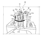
- FIG. 3 is a perspective view showing the periphery of the accommodating portion 60 of the present embodiment.
- the second terminal 50 is indicated by a chain double-dashed line.
- the accommodating portion 60 of the present embodiment includes an accommodating portion main body 61 and a pair of first regulating portions 62 projecting from the accommodating portion main body 61 toward one side in the axial direction (upper side in FIG. 3).
- a pair of second regulating portions 63 provided in the accommodating portion main body 61 is provided.
- the accommodating portion main body 61 has a substantially rectangular parallelepiped shape.
- the accommodating portion main body 61 is provided with a holding hole 61a for accommodating and holding the first terminal 40.
- An opening is formed in the upper surface 61b of the accommodating portion main body 61 by a holding hole 61a.
- a slit 61d is provided on the radial outer side surface 61c of the accommodating portion main body 61.
- the slit 61d is formed so as to communicate with the holding hole 61a.
- the pair of first regulating portions 62 of the present embodiment are protrusions protruding from the upper surface 61b of the accommodating portion main body 61 toward one side in the axial direction (upper side in FIG. 3).
- the pair of first regulating portions 62 are arranged radially outside the holding holes 61a. Further, the pair of first regulating portions 62 are arranged at intervals in the circumferential direction. More specifically, the pair of first regulating portions 62 are provided on both sides in the circumferential direction with the slits 61d provided in the accommodating portion main body 61 interposed therebetween. Further, the pair of first regulating portions 62 is provided integrally with the accommodating portion main body 61.
- the pair of first regulating units 62 of the present embodiment regulates the movement of the second terminal 50 in the circumferential direction.
- the first regulation unit 62 is a portion (for example, a flat plate portion 54) other than the portion of the second terminal 50 that is inserted into and fitted to the first terminal 40 (specifically, the electrical connection portion 53). ) Is restricted in the circumferential direction (see arrow A in FIG. 3).
- the electrical connection portion 53 of the second terminal 50 is fitted and fixed to the first terminal 40. Therefore, when a force is applied to the wiring connection portion 52 of the second terminal 50 in the circumferential direction, the portion of the second terminal 50 on the wiring connection portion 52 side of the bending portion 51 moves in the circumferential direction with the bending portion 51 as the base point. try to.
- the first regulating portion 62 interferes with the flat plate portion 54 of the second terminal 50 when the portion of the second terminal 50 on the wiring connection portion 52 side tries to move in the circumferential direction with the bent portion 51 as the base point. , Regulate its movement. As a result, the first regulation unit 62 suppresses the deformation of the second terminal 50 when a force in the circumferential direction is applied to the wiring connection portion 52 of the second terminal 50.
- the pair of second regulating portions 63 of the present embodiment are trapezoidal provided in the accommodating portion main body 61.
- the second regulating portion 63 is provided so as to project from the pair of inner surfaces 61e of the accommodating portion main body 61 that defines the slit 61d. That is, the second regulation unit 63 is provided so as to project into the slit 61d.
- the pair of second regulating units 63 are arranged so as to face each other at intervals in the circumferential direction.
- Each of the pair of second regulatory units 63 has a regulatory surface 63a.
- the second regulation unit 63 regulates the movement of the second terminal 50 to one side in the axial direction (lower side in FIG. 3) (see arrow B in the figure).
- the second regulation unit 63 is a portion (for example, a flat plate portion 54) other than the portion of the second terminal 50 that is inserted into and fitted to the first terminal 40 (specifically, the electrical connection portion 53). ) Is restricted to move to one side in the axial direction.
- the electrical connection portion 53 of the second terminal 50 is fitted and fixed to the first terminal 40. Therefore, when a force in one axial direction (downward in FIG. 3) acts on the wiring connection portion 52 of the second terminal 50, the portion on the wiring connection portion 52 side of the bending portion 51 of the second terminal 50 becomes. It tries to move downward with the bent portion 51 as a base point.
- the regulation surface 63a of the second regulation portion 63 interferes with the flat plate portion 54 of the second terminal 50 when the portion of the second terminal 50 on the wiring connection portion 52 side tries to move downward with the bent portion 51 as the base point. By doing so, the movement is regulated.
- the second regulating unit 63 suppresses the deformation of the second terminal 50 when a force acting in one axial direction (downward in FIG. 3) acts on the wiring connecting portion 52 of the second terminal 50. do.
- FIG. 4 is a cross-sectional view taken along the line IV-IV of FIG.
- the first regulation portion 62 of the present embodiment is provided in the accommodating portion 60 at a position closer to the wiring connection portion 52 than the bending portion 51. Specifically, the distance D1 between the first regulating portion 62 and the wiring connecting portion 52 of the present embodiment is shorter than the distance D2 between the first regulating portion 62 and the bending portion 51.
- the regulation surface 63a of the second regulation unit 63 is arranged on one side (lower side in FIG. 4) in the axial direction from the upper surface 61b of the accommodation unit main body 61.
- the upper surface 62a of the first regulating portion 62 is arranged on the other side (upper side in FIG. 4) in the axial direction from the upper surface 61b of the accommodating portion main body 61.
- FIG. 5 is a schematic view for explaining the manufacturing method of the stator 2 of the present embodiment, and shows a view of the stator 2 as viewed from the axial direction.
- FIG. 5 shows only a part of the wiring 70s out of the plurality of wirings 70.
- the stator 2 of the present embodiment is molded by injecting BMC resin into the mold M in a state where components such as the stator core 10 (shown in FIG. 1), the coil 20, and the insulator 30 are arranged inside the mold M. NS. That is, the stator 2 is manufactured by insert molding components such as the stator core 10, the coil 20, and the insulator 30.
- the insulator 30 is attached to the stator core 10 (shown in FIG. 1), and the coil 20 is wound around the teeth 12 of the stator core 10.
- the first terminal 40 is fitted into the holding hole 61a of the insulator 30.
- the first terminal 40 and the lead wire of the coil 20 are electrically connected.
- the second terminal 50 to which the wiring 70 is connected to the wiring connection portion 52 is fitted to the first terminal 40, and the first terminal 40 and the second terminal 50 are connected.
- BMC resin is injected inward in the radial direction from two locations separated in the circumferential direction with respect to the components of the stator 2 such as the stator core 10, the coil 20, and the insulator 30. (See the arrow in FIG. 5).
- the resin flows have directions that intersect in the axial direction.
- the resin injection direction is not limited to the direction intersecting the axial direction (the radial direction in the present embodiment), and may be the direction along the axial direction.
- the second terminal 50 moves or moves with respect to the first terminal 40. Deformation due to this movement may occur.
- the contact area between the first terminal 40 and the second terminal 50 becomes smaller, and between the first terminal 40 and the second terminal 50. Contact resistance may increase.
- the first regulation unit 62 restricts the movement of the portion other than the electrical connection portion 53 inserted into the first terminal 40 at the second terminal 50 in the circumferential direction.
- the first regulation unit 62 restricts the movement of the portion other than the electrical connection portion 53 inserted into the first terminal 40 at the second terminal 50 to one side in the axial direction. Therefore, when a force unilaterally in the axial direction acts on the second terminal 50, it is possible to prevent the second terminal 50 from being unintentionally moved with respect to the first terminal 40 or being deformed due to this movement. can. As a result, an increase in contact resistance between the first terminal 40 and the second terminal 50 can be suppressed.
- the resin injection direction at the time of insert molding is one side direction in the axial direction (downward in FIG. 3)
- the flow of the resin in the mold has one side direction in the axial direction. At this time, due to the resin flowing in one side in the axial direction, a force in one side in the axial direction acts on the second terminal 50.
- the techniques of the present disclosure are sometimes effective in such cases.
- the electrical connection portion 53 of the second terminal 50 is inserted into the first terminal 40 and fitted. Therefore, when a force in the circumferential direction acts on the wiring connection portion 52 of the second terminal 50, the portion of the second terminal 50 on the wiring connection portion 52 side of the bending portion 51 tends to move with the bending portion 51 as the base point. .. Since the first regulating portion 62 is provided at a position closer to the wiring connection portion 52 than the bending portion 51 in the accommodating portion 60, the first regulating portion 62 is located at the bending portion 51 rather than the wiring connecting portion 52 in the accommodating portion 60. Compared with the case where the wiring connection portion 52 is provided at a close position, the movement of the wiring connection portion 52 or the deformation caused by this movement can be suppressed.
- the outer rotor type motor has been described, but the technique of the present disclosure may be applied to the inner rotor type motor.
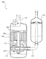
- FIG. 6 is a vertical cross-sectional view of the compressor 100 provided with the motor 101 according to the second embodiment.
- the motor 101 of the present embodiment is different from the motor 1 of the first embodiment in that it is an inner rotor type motor.
- the motor 101 of the present embodiment is similar to the motor 1 of the first embodiment in that the technique of the present disclosure is applied. That is, the motor 101 of the present embodiment also adopts a structure that suppresses an increase in contact resistance between terminals as described in the first embodiment.
- the motor 101 of the present embodiment includes an annular stator 102 and a rotor 103 surrounded by the stator 102.
- the compressor 100 of the present embodiment is arranged in a closed container 110, a compression mechanism unit 111 arranged in the closed container 110, and a compression mechanism unit 111 arranged in the closed container 110, and the compression mechanism unit 111 is attached to the shaft 112.
- a motor 101 that is driven via the motor 101 is provided.
- This compressor 100 can be used, for example, in an air conditioner.
- the compressor 100 is a so-called vertical high-pressure dome type rotary compressor, in which the compression mechanism portion 111 is arranged on the lower side in the closed container 110, and the motor 101 is arranged on the upper side of the compression mechanism portion 111. There is.
- the rotor 103 of the motor 101 drives the compression mechanism 111 via the shaft 112.
- the motor 101 of this application example is an inner rotor type motor, and the technique of the present disclosure is applied.
- the compression mechanism unit 111 sucks the refrigerant gas from the accumulator 113 through the suction pipe 114.
- This refrigerant gas is obtained by controlling a condenser, an expansion mechanism, and an evaporator (not shown) constituting an air conditioner as an example of a refrigerating system together with a compressor 100.
- the compressor 100 discharges the compressed high-temperature and high-pressure refrigerant gas from the compression mechanism unit 111 to fill the inside of the closed container 110.
- This refrigerant gas is discharged to the outside from a discharge pipe 115 provided on the upper side of the motor 101 through a gap between the rotor 103 and the stator 102 of the motor 101.
- the second embodiment has the same effect as that of the first embodiment.
- FIG. 7 is a vertical cross-sectional view of the fan motor 200 including the motor 201 according to the third embodiment.
- the motor 201 of this embodiment is an outer rotor type. That is, the motor 201 of the present embodiment includes an annular stator 202 and an annular rotor 203 arranged so as to surround the stator 202.
- the stator 202 of the present embodiment has the same configuration as the stator 2 of the first embodiment, and detailed description thereof will be omitted.
- the rotor 203 has the same configuration as the rotor 3 of the first embodiment, and detailed description thereof will be omitted.
- the stator 202 of the motor 201 of this embodiment is covered with a resin mold portion 210.
- the resin mold portion 210 is made of BMC resin, which is a thermosetting resin material.
- the fan motor 200 of the present embodiment includes a fan 204 driven by the motor 201.
- the fan 204 of this embodiment is an axial fan. Note that, in FIG. 7, the fan 204 is schematically shown and may differ from the actual size.
- the fan 204 is connected to the shaft 211.
- the shaft 211 is rotatably supported with respect to the resin mold portion 210 by a bearing 210a fixed to the resin mold portion 210. Further, the shaft 211 is fixed to the rotor 203.
- the third embodiment has the same effect as that of the first embodiment.
- the accommodating portion 60 is provided integrally with the first insulator 31 of the insulator 30, but the present invention is not limited to this, and the accommodating portion 60 may be provided separately from the insulator 30. ..
- the first regulation unit 62 is a protrusion, but the shape, position, and size of the first regulation unit 62 are not limited to the protrusions, and the shape, position, and size of the first regulation unit 62 are the shape of the second terminal and the like. It may be changed as appropriate according to the above.
- the stator core 10 is divided into a plurality of stator core pieces 10P, but the present invention is not limited to this, and the stator core 10 may be composed of a single member. Further, the stator 2 is composed of a plurality of stator units 2U, but is not limited thereto.
- the motor according to the present disclosure is not limited to the compressor and the fan motor, and may be applied to a device using another motor.
- Stator 103 Rotor 110 ... Sealed container 111 ... Compression mechanism 112 ... Shaft 113 ... Accumulator 114 ... Suction pipe 115 ... Discharge pipe 200 ... Fan motor 201 ... Motor 202 ... Stator 203 ... Rotor 204 ... Fan 210 ... Resin mold 210a ... Bearing 211 ... Shaft
Landscapes
- Engineering & Computer Science (AREA)
- Power Engineering (AREA)
- Mechanical Engineering (AREA)
- General Engineering & Computer Science (AREA)
- Insulation, Fastening Of Motor, Generator Windings (AREA)
Abstract
モータは、環状のステータコアと、ステータコアのティースに巻回されたコイルと、コイルと電気的に接続された第1端子(40)と、第1端子(40)を収容する収容部(60)と、収容部(60)に収容された第1端子(40)に少なくとも一部挿入された第2端子(50)とを備える。第2端子(50)は、第1端子(40)に挿入され、第1端子(40)と電気的に接続された電気接続部(53)を有する。収容部(60)は、第2端子(50)において上記電気接続部(53)以外の部分が、ステータコア(10)の周方向に移動することを規制する第1規制部(62)を有する。
Description
本開示は、モータ、圧縮機、及びファンモータに関する。
従来のモータとしては、ステータを金型内にインサートし、BMC樹脂を射出して製作されるモータハウジングを有するものがある(特許文献1参照)。このステータは、ステータコアと、ステータコアに取り付けされる上部インシュレータとを備える。上部インシュレータにはマグメイト部が形成されており、マグメイト部にマグメイト端子が嵌入されて、マグメイト部とマグメイト端子とが電気的に接続されている。
上記従来のモータでは、例えば、射出成形時の樹脂の圧力によって、マグメイト端子が意図せず変形又は移動すると、マグメイト部とマグメイト端子との間の接触面積が小さくなり、接触抵抗が増大する恐れがある。
本開示は、端子間の接触抵抗の増加を抑制できるモータ、圧縮機、及びファンモータを提案する。
本開示の一態様に係るモータは、
環状のステータコアと、
上記ステータコアのティースに巻回されたコイルと、
上記コイルと電気的に接続された第1端子と、
上記第1端子を収容する収容部と、
上記収容部に収容された上記第1端子に少なくとも一部が挿入された第2端子と
を備え、
上記第2端子は、上記第1端子に挿入されて、上記第1端子と電気的に接続された電気接続部を有し、
上記収容部は、上記第2端子において上記電気接続部以外の部分が、上記ステータコアの周方向に移動することを規制する第1規制部を有する、ことを特徴とする。
環状のステータコアと、
上記ステータコアのティースに巻回されたコイルと、
上記コイルと電気的に接続された第1端子と、
上記第1端子を収容する収容部と、
上記収容部に収容された上記第1端子に少なくとも一部が挿入された第2端子と
を備え、
上記第2端子は、上記第1端子に挿入されて、上記第1端子と電気的に接続された電気接続部を有し、
上記収容部は、上記第2端子において上記電気接続部以外の部分が、上記ステータコアの周方向に移動することを規制する第1規制部を有する、ことを特徴とする。
本開示によれば、第2端子において第1端子に挿入された電気接続部以外の部分が、ステータコアの周方向に移動することが規制されるので、第2端子の第1端子に対する意図しない移動及びこの移動に起因する変形が発生し難くなる。これにより、第1端子と第2端子との間の接触状態が変化して接触面積が小さくなることが抑制される。その結果、第1端子と第2端子との間の接触抵抗の増加を抑制できる。
一実施形態では、上記収容部は、上記第1端子を収容する収容部本体を備え、
上記第1規制部は、上記収容部本体から突出した突起である。
上記第1規制部は、上記収容部本体から突出した突起である。
一実施形態では、上記収容部は、上記第2端子において上記電気接続部以外の部分が、上記ステータコアの軸方向の少なくとも一方へ移動することを規制する第2規制部を有する。
上記実施形態によれば、第2規制部により、第2端子において第1端子に挿入された電気接続部以外の部分が、ステータコアの軸方向の少なくとも一方へ移動することが規制されるので、第2端子の第1端子に対する意図しない移動又はこの移動に起因する変形が発生し難くなる。これにより、第1端子と第2端子との間の接触状態が変化して接触面積が小さくなることが抑制される。その結果、第1端子と第2端子との間の接触抵抗の増加を抑制できる。
一実施形態では、
上記第2端子は、屈曲部において屈曲しており、
上記第2端子は、上記屈曲部に対して上記電気接続部と反対側に設けられた配線接続部を備え、
上記第1規制部は、上記収容部において上記屈曲部よりも上記配線接続部に近い位置に設けられている。
上記第2端子は、屈曲部において屈曲しており、
上記第2端子は、上記屈曲部に対して上記電気接続部と反対側に設けられた配線接続部を備え、
上記第1規制部は、上記収容部において上記屈曲部よりも上記配線接続部に近い位置に設けられている。
上記実施形態では、電気接続部が第1端子に挿入されているので、第2端子の配線接続部側に周方向の力が作用した場合に、第2端子の配線接続部側の部分は、屈曲部を基点に移動しようとする。上記実施形態によれば、第1規制部が屈曲部よりも配線接続部に近い位置に設けられているので、第1規制部が配線接続部よりも屈曲部に近い位置に設けられている場合と比較して、第2端子の配線接続部側の部分の移動又はこの移動に起因する変形を抑制できる。
一実施形態のモータは、上記ステータコアに取り付けられたインシュレータを備え、
上記収容部は、上記インシュレータに一体に設けられている。
上記収容部は、上記インシュレータに一体に設けられている。
本開示の他の態様に係る圧縮機は、
上述のモータと、
上記モータにより駆動される圧縮機構部と
を備える。
上述のモータと、
上記モータにより駆動される圧縮機構部と
を備える。
本開示の更に他の態様に係るファンモータは、
上述のモータと、
上記モータにより駆動されるファンと
を備える。
上述のモータと、
上記モータにより駆動されるファンと
を備える。
以下、添付図面を参照して、本開示の実施形態に係るモータ、圧縮機、及びファンモータを説明する。
(第1実施形態)
図1は、第1実施形態に係るモータ1の部分断面図である。図1において、右側半分は、モータ1の中心軸方向から見た外形図を示し、左側半分は、モータ1の中心軸方向に直交する断面における断面図を示す。
図1は、第1実施形態に係るモータ1の部分断面図である。図1において、右側半分は、モータ1の中心軸方向から見た外形図を示し、左側半分は、モータ1の中心軸方向に直交する断面における断面図を示す。
図1を参照すると、本実施形態のモータ1は、所謂アウターロータ型の三相交流モータである。本実施形態のモータ1は、環状のステータ2と、ステータ2を取り囲むように配置された環状のロータ3とを備える。
以下の説明において、「軸方向」とはモータ1の中心軸方向を示し、「径方向」とはモータ1の中心軸Cを中心とする径方向を示し、「周方向」とはモータ1の中心軸Cを中心とする周方向を示す場合がある。また、本実施形態において、ステータ2の中心軸と、ロータ3の中心軸とは、モータ1の中心軸Cと一致している。つまり、「軸方向」、「径方向」、及び「周方向」という用語は、ステータ2又はロータ3の「軸方向」、「径方向」、及び「周方向」をそれぞれ示す。
ステータ2は、環状のステータコア10と、ステータコア10に巻回された複数(本実施形態では12個)のコイル20と、ステータコア10とコイル20との間に設けられた複数(本実施形態では12個)のインシュレータ30とを備える。また、ステータ2は、図示しないが、熱硬化性樹脂材料であるBMC樹脂(Bulk Molding Compound)によって覆われるように、樹脂モールドされている。
ステータコア10は、導電性を有する軟磁性体からなる積層鋼板で形成されている。ステータコア10は、環状のバックヨーク部11と、バックヨーク部11の外周面から径方向外側に向けて延びる複数(本実施形態では12個)のティース12とを備える。
ステータコア10は、複数(本実施形態では12個)のステータコアピース10Pが周方向に連結されて構成されている。各ステータコアピース10Pには、1つのティース12が設けられている。
コイル20は、エナメル樹脂のような絶縁材料で被覆された銅線であり、径方向に沿う軸を巻回軸としてステータコア10のティース12に巻回されている。
インシュレータ30は、絶縁性の樹脂材料により形成されており、コイル20を流れる電流がステータコア10に伝わらないようにステータコア10とコイル20との間を絶縁している。
本実施形態のステータ2は、複数(本実施形態では12個)のステータユニット2Uが周方向に連結されて構成されている。各ステータユニット2Uは、1つのステータコアピース10Pと、1つのコイル20と、1つのインシュレータ30とを含む。
ロータ3は、円筒状であり、ステータ2の径方向外側に回転可能に配置されている。ロータ3は、周方向においてN極とS極とが交互に配置されるように多極着磁されている。
図2は、本実施形態のステータユニット2Uの分解斜視図である。図2では、コイル20(図1に示す)の図示を省略している。
図2を参照すると、ステータユニット2Uは、前述したように、ステータコアピース10Pと、ステータコアピース10Pの一部を覆うインシュレータ30と、ステータコアピース10Pのティース12に巻回されたコイル20(図1に示す)とを備える。また、ステータユニット2Uは、コイル20(図1に示す)と電気的に接続された第1端子40と、第1端子40に挿入されて嵌合する第2端子50とを備える。
インシュレータ30は、ステータコアピース10Pの軸方向の一方側(図2において上側)に取り付けられる第1インシュレータ31と、ステータコアピース10Pの軸方向の他方側(図2において下側)に取り付けられる第2インシュレータ32とを備える。第1インシュレータ31と第2インシュレータ32とは、ステータコアピース10Pのティース12を覆うようにステータコアピース10Pに対して取り付けられる。
第1インシュレータ31は、第1端子40を収容するための収容部60を備える。本実施形態の収容部60は、有底箱形状であり、第1インシュレータ31と一体に設けられている。また、収容部60は、第1インシュレータ31の径方向内側の端部に設けられている。
第1端子40は、導電性を有する金属からなるメス端子である。第1端子40は、第1インシュレータ31に設けられた収容部60に収容されている。また、第1端子40は、コイル20(図1に示す)から引き出されたリード線(図示せず)と接続するための結線溝41と、第2端子50と嵌合するための受部42とを備える。第1端子40は、収容部60に収容された状態で、結線溝41にコイル20のリード線が嵌合することで、コイル20と電気的に接続される。また、第1端子40は、受部42に第2端子50が嵌合することで、第2端子50と電気的に接続される。
第2端子50は、導電性を有する金属からなり、メス端子である第1端子40に対応するオス端子である。第2端子50は、屈曲部51で屈曲したL字状である。第2端子50は、配線70に接続された配線接続部52と、第1端子40と電気的に接続された電気接続部53とを備える。配線接続部52は、屈曲部51に対して電気接続部53と反対側に設けられている。また、第2端子50は、屈曲部51から配線接続部52に延びた板状の平板部54を備える。
第2端子50は、第1端子40に挿入されて連結される。具体的には、第2端子50は、電気接続部53が第1端子40の受部42に挿入されて嵌合することで、第1端子40と連結される。これにより、第1端子40と第2端子50とが電気的に接続される。
図3は、本実施形態の収容部60の周辺を示す斜視図である。図3において、第2端子50は、2点鎖線で示す。
図3を参照すると、本実施形態の収容部60は、収容部本体61と、収容部本体61から軸方向の一方側(図3において上側)に向けて突出する一対の第1規制部62と、収容部本体61内に設けられた一対の第2規制部63とを備える。
収容部本体61は、略直方体形状である。収容部本体61には、第1端子40を収容して保持するための保持穴61aが設けられている。収容部本体61の上面61bには、保持穴61aによって開口が形成されている。
収容部本体61の径方向外側の側面61cには、スリット61dが設けられている。スリット61dは、保持穴61aに連通するように形成されている。
本実施形態の一対の第1規制部62は、収容部本体61の上面61bから軸方向の一方側(図3において上側)に向けて突出した突起である。一対の第1規制部62は、保持穴61aよりも径方向外側に配置されている。また、一対の第1規制部62は、周方向に間隔を開けて配置されている。より詳細には、一対の第1規制部62は、収容部本体61に設けられたスリット61dを挟んで周方向の両側に設けられている。また、一対の第1規制部62は、収容部本体61と一体に設けられている。
本実施形態の一対の第1規制部62は、第2端子50の周方向の移動を規制する。具体的には、第1規制部62は、第2端子50のうち第1端子40に挿入されて嵌合した部分(具体的には、電気接続部53)以外の部分(例えば、平板部54)の周方向への移動(図3の矢印A参照)を規制する。
本実施形態では、第2端子50の電気接続部53が第1端子40と嵌合して固定されている。このため、第2端子50の配線接続部52に周方向の力が作用すると、第2端子50の屈曲部51よりも配線接続部52側の部分は、屈曲部51を基点として周方向に移動しようとする。第1規制部62は、第2端子50の配線接続部52側の部分が、屈曲部51を基点として周方向に移動しようとしたときに、第2端子50の平板部54と干渉することで、その移動を規制する。これにより、第1規制部62は、第2端子50の配線接続部52に周方向の力が作用したときに、第2端子50が変形することを抑制する。
本実施形態の一対の第2規制部63は、収容部本体61に設けられた台状である。第2規制部63は、スリット61dを画定する収容部本体61の一対の内面61eから突出するように設けられている。つまり、第2規制部63は、スリット61d内に突出するように設けられている。一対の第2規制部63は、互いに対向するように周方向に間隔を開けて配置されている。一対の第2規制部63のそれぞれは、規制面63aを有する。
第2規制部63は、第2端子50の軸方向一方側(図3における下側)への移動(図中矢印B参照)を規制する。具体的には、第2規制部63は、第2端子50のうち第1端子40に挿入されて嵌合した部分(具体的には、電気接続部53)以外の部分(例えば、平板部54)の軸方向一方側への移動を規制する。
本実施形態では、前述したように、第2端子50の電気接続部53が第1端子40と嵌合して固定されている。このため、第2端子50の配線接続部52に軸方向の一方側向き(図3において下向き)の力が作用すると、第2端子50の屈曲部51よりも配線接続部52側の部分は、屈曲部51を基点として下向きに移動しようとする。第2規制部63の規制面63aは、第2端子50の配線接続部52側の部分が、屈曲部51を基点として下向きに移動しようとしたときに、第2端子50の平板部54と干渉することで、その移動を規制する。これにより、第2規制部63は、第2端子50の配線接続部52に軸方向の一方側向き(図3において下向き)の力が作用したときに、第2端子50が変形することを抑制する。
図4は、図1のIV-IV線に沿った断面図である。
図4を参照すると、本実施形態の第1規制部62は収容部60において、屈曲部51よりも配線接続部52に近い位置に設けられている。具体的には、本実施形態の第1規制部62と配線接続部52との間の距離D1は、第1規制部62と屈曲部51との間の距離D2よりも短い。
また、第2規制部63の規制面63aは、収容部本体61の上面61bよりも軸方向の一方側(図4において下側)に配置されている。一方で、第1規制部62の上面62aは、収容部本体61の上面61bよりも軸方向の他方側(図4において上側)に配置されている。
(ステータの製造方法)
以下、図5を参照して、本実施形態のモータ1のステータ2の製造方法を説明する。図5は、本実施形態のステータ2の製造方法を説明するための模式的な図であり、ステータ2を軸方向から見た図を示す。図5では、複数の配線70のうち一部の配線70のみを示す。
以下、図5を参照して、本実施形態のモータ1のステータ2の製造方法を説明する。図5は、本実施形態のステータ2の製造方法を説明するための模式的な図であり、ステータ2を軸方向から見た図を示す。図5では、複数の配線70のうち一部の配線70のみを示す。
本実施形態のステータ2は、ステータコア10(図1に示す)、コイル20、インシュレータ30などの構成要素が金型M内部に配置された状態で、金型MにBMC樹脂を射出して成形される。つまり、ステータ2は、ステータコア10、コイル20、及びインシュレータ30などの構成要素をインサート成形することで製造される。
まず、ステータコア10(図1に示す)に対してインシュレータ30を取り付け、ステータコア10のティース12にコイル20を巻回する。次に、インシュレータ30の保持穴61aに第1端子40を嵌め込む。このとき、第1端子40とコイル20のリード線とが、電気的に接続される。その後、具体的には、配線接続部52に配線70が接続された第2端子50を第1端子40に嵌合させて、第1端子40と第2端子50とを連結する。
本実施形態の金型Mには、ステータコア10、コイル20、及びインシュレータ30などのステータ2の構成要素に対して、周方向に離間した2箇所からBMC樹脂が径方向内側に向かって注入される(図5の矢印参照)。本実施形態では金型Mの内部において、樹脂の流れは、軸方向に交差する方向を有する。なお、樹脂の注入方向は、軸方向に交差する方向(本実施形態では径方向)に限定されず、軸方向に沿った方向であってもよい。
本実施形態のモータ1によれば、以下の作用効果を奏する。
(1) 例えば、インサート成形の際の樹脂の圧力、又は配線作業時における配線70の張力等によって、第2端子50に力が作用したときに、第2端子50の第1端子40に対する移動又はこの移動に起因する変形が発生する恐れがある。第2端子50が第1端子40に対して移動及び/又は変形すると、第1端子40と第2端子50との間の接触面積が小さくなり、第1端子40と第2端子50との間の接触抵抗が増大することがある。これに対して、本実施形態のモータ1では、第1規制部62が、第2端子50において第1端子40に挿入された電気接続部53以外の部分が周方向に移動することを規制するので、第2端子50に対して周方向の力が作用したときに、第2端子50が第1端子40に対して意図せず移動及び/又は変形することを抑制できる。これにより、第1端子40と第2端子50との間の接触抵抗の増加を抑制できる。例えば、本実施形態のように、インサート成形の際の樹脂の流れが、軸方向に交差する方向を有する場合、周方向に流れる樹脂によって、第2端子50には、周方向の力が作用する。本開示の技術は、このような場合に特に有効である。
(2) 本実施形態のモータ1では、第1規制部62が、第2端子50において第1端子40に挿入された電気接続部53以外の部分が軸方向の一方側へ移動することを規制するので、第2端子50に対して軸方向の一方側向きの力が作用したときに、第2端子50の第1端子40に対する意図しない移動又はこの移動に起因する変形が発生することを抑制できる。これにより、第1端子40と第2端子50との間の接触抵抗の増加を抑制できる。例えば、インサート成形の際の樹脂の注入方向が、軸方向の一方側向き(図3おいて下向き)であるとき、金型内の樹脂の流れは、軸方向の一方側向きを有する。このとき、軸方向の一方側向きに流れる樹脂によって、第2端子50には、軸方向の一方側向きの力が作用する。本開示の技術は、このような場合に時に有効である。
(3) 本実施形態では、第2端子50の電気接続部53が第1端子40に挿入されて嵌合している。このため、第2端子50の配線接続部52に周方向の力が作用すると、第2端子50の屈曲部51よりも配線接続部52側の部分は、屈曲部51を基点として移動しようとする。第1規制部62が、収容部60において屈曲部51よりも配線接続部52に近い位置に設けられているので、第1規制部62が収容部60において配線接続部52よりも屈曲部51に近い位置に設けられている場合と比較して、配線接続部52の移動又はこの移動に起因する変形を抑制できる。
上記第1実施形態では、アウターロータ型のモータについて説明したが、インナーロータ型のモータに本開示の技術を適用してもよい。
(第2実施形態)
図6は、第2実施形態に係るモータ101を備えた圧縮機100の縦断面図である。本実施形態のモータ101は、インナーロータ型のモータである点で第1実施形態のモータ1と相違する。一方で、本実施形態のモータ101は、本開示の技術が適用されている点で、第1実施形態のモータ1と同様である。つまり、本実施形態のモータ101にも、上記第1実施形態で説明したような、端子間の接触抵抗の増加を抑制するような構造などが採用されている。
図6は、第2実施形態に係るモータ101を備えた圧縮機100の縦断面図である。本実施形態のモータ101は、インナーロータ型のモータである点で第1実施形態のモータ1と相違する。一方で、本実施形態のモータ101は、本開示の技術が適用されている点で、第1実施形態のモータ1と同様である。つまり、本実施形態のモータ101にも、上記第1実施形態で説明したような、端子間の接触抵抗の増加を抑制するような構造などが採用されている。
本実施形態のモータ101は、環状のステータ102と、ステータ102に取り囲まれたロータ103とを備える。
図6を参照すると、本実施形態の圧縮機100は、密閉容器110と、この密閉容器110内に配置された圧縮機構部111と、密閉容器110内に配置され、圧縮機構部111をシャフト112を介して駆動するモータ101とを備える。この圧縮機100は、例えば空気調和機に使用可能である。
圧縮機100は、いわゆる縦型の高圧ドーム型のロータリ圧縮機であって、密閉容器110内の下側に圧縮機構部111を配置し、その圧縮機構部111の上側にモータ101を配置している。このモータ101のロータ103によってシャフト112を介して圧縮機構部111を駆動するようにしている。本適用例のモータ101は、インナーロータ型のモータであり、本開示の技術が適用されている。
圧縮機構部111は、圧縮機100が空気調和機に使用されるとき、アキュムレータ113から吸入管114を通して冷媒ガスを吸入する。この冷媒ガスは、冷凍システムの一例としての空気調和機を構成する図示しない凝縮器、膨張機構、及び蒸発器を圧縮機100と共に制御することによって得られる。
また、圧縮機100は、圧縮した高温高圧の冷媒ガスを、圧縮機構部111から吐出して密閉容器110の内部に満たす。この冷媒ガスは、モータ101のロータ103とステータ102との間の隙間などを通って、モータ101の上側に設けられた吐出管115から外部に吐出されるようになっている。
第2実施形態では、第1実施形態と同様の作用効果を奏する。
(第3実施形態)
図7は、第3実施形態に係るモータ201を備えるファンモータ200の縦断面図である。
図7は、第3実施形態に係るモータ201を備えるファンモータ200の縦断面図である。
本実施形態のモータ201は、アウターロータ型である。つまり、本実施形態のモータ201は、環状のステータ202と、ステータ202を取り囲むように配置された環状のロータ203とを備える。本実施形態のステータ202は、上記第1実施形態のステータ2と同様の構成を有しており、その詳細な説明を省略する。同様に、ロータ203は、上記第1実施形態のロータ3と同様の構成を有しており、その詳細な説明を省略する。
本実施形態のモータ201のステータ202は、樹脂モールド部210によって覆われている。樹脂モールド部210は、熱硬化性樹脂材料であるBMC樹脂で形成されている。
また、本実施形態のファンモータ200は、モータ201によって駆動されるファン204を備える。
本実施形態のファン204は、軸流ファンである。なお、図7において、ファン204は模式的に示されており、実際の大きさとは異なる場合がある。
ファン204は、シャフト211と連結されている。シャフト211は、樹脂モールド部210に固定された軸受210aによって、樹脂モールド部210に対して回転可能に支持されている。また、シャフト211は、ロータ203に固定されている。
第3実施形態では、第1実施形態と同様の作用効果を奏する。
以上、実施形態を説明したが、特許請求の趣旨及び範囲から逸脱することなく、形態や詳細の多様な変更が可能なことが理解されるであろう。
例えば、上記第1~第3実施形態では、収容部60は、インシュレータ30の第1インシュレータ31と一体に設けられていたが、これに限定されず、インシュレータ30と別体に設けられてもよい。
上記第1~第3実施形態では、第1規制部62は、突起であったが、これに限定されず、第1規制部62の形状、位置、及び大きさは、第2端子の形状等に応じて適宜変更されてもよい。
上記第1~第3実施形態では、ステータコア10は、複数のステータコアピース10Pに分割されていたが、これに限定されず、ステータコア10は、単一の部材からなってもよい。また、ステータ2は、複数のステータユニット2Uから構成されていたが、これに限定されない。
本開示に係るモータは、圧縮機及びファンモータに限らず、他のモータを使用する装置に適用されてもよい。
1…モータ
2…ステータ
3…ロータ
10…ステータコア
10P…ステータコアピース
11…バックヨーク部
12…ティース
20…コイル
30…インシュレータ
31…第1インシュレータ
32…第2インシュレータ
40…第1端子
50…第2端子
51…屈曲部
52…配線接続部
53…電気接続部
54…平板部
60…収容部
61…収容部本体
61a…保持穴
61b…上面
61c…側面
61d…スリット
62…第1規制部
63…第2規制部
63a…規制面
100…圧縮機
101…モータ
102…ステータ
103…ロータ
110…密閉容器
111…圧縮機構部
112…シャフト
113…アキュムレータ
114…吸入管
115…吐出管
200…ファンモータ
201…モータ
202…ステータ
203…ロータ
204…ファン
210…樹脂モールド部
210a…軸受
211…シャフト
Claims (7)
- 環状のステータコア(10)と、
上記ステータコア(10)のティース(12)に巻回されたコイル(20)と、
上記コイル(20)と電気的に接続された第1端子(40)と、
上記第1端子(40)を収容する収容部(60)と、
上記収容部(60)に収容された上記第1端子(40)に少なくとも一部が挿入された第2端子(50)と
を備え、
上記第2端子(50)は、上記第1端子(40)に挿入され、上記第1端子(40)と電気的に接続された電気接続部(53)を有し、
上記収容部(60)は、上記第2端子(50)において上記電気接続部(53)以外の部分が、上記ステータコア(10)の周方向に移動することを規制する第1規制部(62)を有する、モータ(1,101,201)。 - 上記収容部(60)は、上記第1端子(40)を収容する収容部本体(61)を備え、
上記第1規制部(62)は、上記収容部本体(61)から突出した突起である、請求項1に記載のモータ(1,101,201)。 - 上記収容部(60)は、上記第2端子(50)において上記電気接続部(53)以外の部分が、上記ステータコア(10)の軸方向の少なくとも一方へ移動することを規制する第2規制部(63)を有する、請求項1又は2に記載のモータ(1,101,201)。
- 上記第2端子(50)は、屈曲部(51)において屈曲しており、
上記第2端子(50)は、上記屈曲部(51)に対して上記電気接続部(53)と反対側に設けられた配線接続部(52)を備え、
上記第1規制部(62)は、上記収容部(60)において上記屈曲部(51)よりも上記配線接続部(52)に近い位置に設けられている、請求項1から3のいずれか1項に記載のモータ(1,101,201)。 - 上記ステータコア(10)に取り付けられたインシュレータ(30)を備え、
上記収容部(60)は、上記インシュレータ(30)に一体に設けられている、請求項1から4のいずれか1項に記載のモータ(1,101,201)。 - 請求項1から5のいずれか1項に記載のモータ(101)と、
上記モータ(101)により駆動される圧縮機構部と
を備える、圧縮機。 - 請求項1から5のいずれか1項に記載のモータ(201)と、
上記モータ(201)により駆動されるファンと
を備える、ファンモータ。
Priority Applications (3)
| Application Number | Priority Date | Filing Date | Title |
|---|---|---|---|
| EP21795289.4A EP4123884A4 (en) | 2020-04-30 | 2021-04-06 | ENGINE, COMPRESSOR AND FAN MOTOR |
| CN202180011926.9A CN115023881A (zh) | 2020-04-30 | 2021-04-06 | 马达、压缩机以及风扇马达 |
| US17/974,293 US20230047683A1 (en) | 2020-04-30 | 2022-10-26 | Motor, compressor, and fan motor |
Applications Claiming Priority (2)
| Application Number | Priority Date | Filing Date | Title |
|---|---|---|---|
| JP2020080622A JP7100276B2 (ja) | 2020-04-30 | 2020-04-30 | モータ、圧縮機、及びファンモータ |
| JP2020-080622 | 2020-04-30 |
Related Child Applications (1)
| Application Number | Title | Priority Date | Filing Date |
|---|---|---|---|
| US17/974,293 Continuation US20230047683A1 (en) | 2020-04-30 | 2022-10-26 | Motor, compressor, and fan motor |
Publications (1)
| Publication Number | Publication Date |
|---|---|
| WO2021220732A1 true WO2021220732A1 (ja) | 2021-11-04 |
Family
ID=78280144
Family Applications (1)
| Application Number | Title | Priority Date | Filing Date |
|---|---|---|---|
| PCT/JP2021/014615 WO2021220732A1 (ja) | 2020-04-30 | 2021-04-06 | モータ、圧縮機、及びファンモータ |
Country Status (5)
| Country | Link |
|---|---|
| US (1) | US20230047683A1 (ja) |
| EP (1) | EP4123884A4 (ja) |
| JP (1) | JP7100276B2 (ja) |
| CN (1) | CN115023881A (ja) |
| WO (1) | WO2021220732A1 (ja) |
Families Citing this family (1)
| Publication number | Priority date | Publication date | Assignee | Title |
|---|---|---|---|---|
| JP7150164B2 (ja) * | 2019-05-29 | 2022-10-07 | 三菱電機株式会社 | 電動機及びそれを備えた圧縮機 |
Citations (6)
| Publication number | Priority date | Publication date | Assignee | Title |
|---|---|---|---|---|
| JPH09312948A (ja) * | 1996-03-19 | 1997-12-02 | Toshiba Corp | 回転電機のステータ |
| JP2001275291A (ja) * | 2000-03-24 | 2001-10-05 | Toshiba Kyaria Kk | 電動機の固定子 |
| US20110316365A1 (en) * | 2010-06-23 | 2011-12-29 | Amotech Co., Ltd | Slim type stator and method of making the same, slim type motor having the stator, and direct drive apparatus for drum-washing machine |
| JP2015516797A (ja) | 2012-06-11 | 2015-06-11 | ニュモテク株式会社New Motech Co., Ltd. | モーター |
| JP2019161894A (ja) * | 2018-03-14 | 2019-09-19 | 日本電産株式会社 | モータ |
| JP2020054137A (ja) * | 2018-09-27 | 2020-04-02 | 日本電産サンキョー株式会社 | モータ |
Family Cites Families (8)
| Publication number | Priority date | Publication date | Assignee | Title |
|---|---|---|---|---|
| JPH0424783Y2 (ja) * | 1986-04-10 | 1992-06-11 | ||
| JP2623438B2 (ja) * | 1993-10-12 | 1997-06-25 | 株式会社ミツバ | コイル線材とリード線の接続構造 |
| JPH08140302A (ja) * | 1994-11-10 | 1996-05-31 | Nippondenso Co Ltd | 磁石式発電機の固定子 |
| KR100883601B1 (ko) | 2007-01-16 | 2009-02-13 | 엘지전자 주식회사 | 모터 |
| KR101389612B1 (ko) | 2013-01-23 | 2014-04-30 | 뉴모텍(주) | 모터의 센서 커버 |
| US10890551B2 (en) * | 2016-07-07 | 2021-01-12 | Ngk Spark Plug Co., Ltd. | Gas sensor and method for manufacturing the same |
| JP6844168B2 (ja) * | 2016-09-20 | 2021-03-17 | アイシン精機株式会社 | ステータおよびステータ製造方法 |
| KR102478247B1 (ko) * | 2017-06-15 | 2022-12-19 | 삼성전자주식회사 | 모터 |
-
2020
- 2020-04-30 JP JP2020080622A patent/JP7100276B2/ja active Active
-
2021
- 2021-04-06 EP EP21795289.4A patent/EP4123884A4/en active Pending
- 2021-04-06 CN CN202180011926.9A patent/CN115023881A/zh active Pending
- 2021-04-06 WO PCT/JP2021/014615 patent/WO2021220732A1/ja unknown
-
2022
- 2022-10-26 US US17/974,293 patent/US20230047683A1/en active Pending
Patent Citations (6)
| Publication number | Priority date | Publication date | Assignee | Title |
|---|---|---|---|---|
| JPH09312948A (ja) * | 1996-03-19 | 1997-12-02 | Toshiba Corp | 回転電機のステータ |
| JP2001275291A (ja) * | 2000-03-24 | 2001-10-05 | Toshiba Kyaria Kk | 電動機の固定子 |
| US20110316365A1 (en) * | 2010-06-23 | 2011-12-29 | Amotech Co., Ltd | Slim type stator and method of making the same, slim type motor having the stator, and direct drive apparatus for drum-washing machine |
| JP2015516797A (ja) | 2012-06-11 | 2015-06-11 | ニュモテク株式会社New Motech Co., Ltd. | モーター |
| JP2019161894A (ja) * | 2018-03-14 | 2019-09-19 | 日本電産株式会社 | モータ |
| JP2020054137A (ja) * | 2018-09-27 | 2020-04-02 | 日本電産サンキョー株式会社 | モータ |
Also Published As
| Publication number | Publication date |
|---|---|
| US20230047683A1 (en) | 2023-02-16 |
| JP7100276B2 (ja) | 2022-07-13 |
| JP2021175351A (ja) | 2021-11-01 |
| EP4123884A4 (en) | 2023-08-30 |
| CN115023881A (zh) | 2022-09-06 |
| EP4123884A1 (en) | 2023-01-25 |
Similar Documents
| Publication | Publication Date | Title |
|---|---|---|
| CN108702052B (zh) | 定子、马达以及压缩机 | |
| US8734133B2 (en) | Fuel pump | |
| CN204205896U (zh) | 马达 | |
| WO2017141877A1 (ja) | 電動装置および電動過給機 | |
| US8415841B2 (en) | Fan motor for circulating cooled air | |
| US10340753B2 (en) | Stator of planar type motor, and planar type motor using same | |
| KR101092320B1 (ko) | 연자성 분말 재료로 제조된 모터용 스테이터 | |
| JP6766666B2 (ja) | 電動圧縮機 | |
| JP2003158846A (ja) | 密閉形圧縮機 | |
| WO2021220732A1 (ja) | モータ、圧縮機、及びファンモータ | |
| JP6914346B2 (ja) | 固定子、電動機、圧縮機、空気調和装置および固定子の製造方法 | |
| KR100677274B1 (ko) | 전동기의 고정자 조립체 | |
| JP2006042409A (ja) | モータ一体型コンプレッサ | |
| JP2883409B2 (ja) | 小型電動機 | |
| JP6854664B2 (ja) | ステータおよび圧縮機 | |
| EP3598612B1 (en) | Stator and electric motor equipped with said stator | |
| US20230358243A1 (en) | Motor, fan, and air conditioner | |
| US11973388B2 (en) | Rotating electric machine, insulator, and assembly method therefor | |
| JPH11315948A (ja) | 電動流量制御弁 | |
| JPH06351184A (ja) | 電動機 | |
| WO2017163539A1 (ja) | 電動式流体機械 | |
| CN211429070U (zh) | 电动机及阀芯驱动装置 | |
| KR102444995B1 (ko) | 차량용 전동 압축기 | |
| WO2022249307A1 (ja) | 電動機及び空気調和機 | |
| AU2019459440B2 (en) | Electric motor, fan, air conditioning device, and method for manufacturing electric motor |
Legal Events
| Date | Code | Title | Description |
|---|---|---|---|
| 121 | Ep: the epo has been informed by wipo that ep was designated in this application |
Ref document number: 21795289 Country of ref document: EP Kind code of ref document: A1 |
|
| ENP | Entry into the national phase |
Ref document number: 2021795289 Country of ref document: EP Effective date: 20221017 |
|
| NENP | Non-entry into the national phase |
Ref country code: DE |