WO2021220390A1 - 無人航空機用フレーム組立体及びこれを備える無人航空機 - Google Patents
無人航空機用フレーム組立体及びこれを備える無人航空機 Download PDFInfo
- Publication number
- WO2021220390A1 WO2021220390A1 PCT/JP2020/018077 JP2020018077W WO2021220390A1 WO 2021220390 A1 WO2021220390 A1 WO 2021220390A1 JP 2020018077 W JP2020018077 W JP 2020018077W WO 2021220390 A1 WO2021220390 A1 WO 2021220390A1
- Authority
- WO
- WIPO (PCT)
- Prior art keywords
- pipe
- unmanned aerial
- aerial vehicle
- frame assembly
- frame
- Prior art date
- Legal status (The legal status is an assumption and is not a legal conclusion. Google has not performed a legal analysis and makes no representation as to the accuracy of the status listed.)
- Ceased
Links
Images




Classifications
-
- B—PERFORMING OPERATIONS; TRANSPORTING
- B64—AIRCRAFT; AVIATION; COSMONAUTICS
- B64U—UNMANNED AERIAL VEHICLES [UAV]; EQUIPMENT THEREFOR
- B64U20/00—Constructional aspects of UAVs
- B64U20/60—UAVs characterised by the material
- B64U20/65—Composite materials
-
- B—PERFORMING OPERATIONS; TRANSPORTING
- B64—AIRCRAFT; AVIATION; COSMONAUTICS
- B64U—UNMANNED AERIAL VEHICLES [UAV]; EQUIPMENT THEREFOR
- B64U20/00—Constructional aspects of UAVs
- B64U20/70—Constructional aspects of the UAV body
-
- B—PERFORMING OPERATIONS; TRANSPORTING
- B64—AIRCRAFT; AVIATION; COSMONAUTICS
- B64U—UNMANNED AERIAL VEHICLES [UAV]; EQUIPMENT THEREFOR
- B64U10/00—Type of UAV
- B64U10/10—Rotorcrafts
- B64U10/13—Flying platforms
- B64U10/16—Flying platforms with five or more distinct rotor axes, e.g. octocopters
-
- B—PERFORMING OPERATIONS; TRANSPORTING
- B64—AIRCRAFT; AVIATION; COSMONAUTICS
- B64U—UNMANNED AERIAL VEHICLES [UAV]; EQUIPMENT THEREFOR
- B64U50/00—Propulsion; Power supply
- B64U50/10—Propulsion
- B64U50/19—Propulsion using electrically powered motors
Definitions
- This disclosure relates to a frame assembly for an unmanned aerial vehicle and an unmanned aerial vehicle equipped with the frame assembly.
- Patent Document 1 an air vehicle composed of two frames arranged in each of the first direction and the second direction intersecting each other is known (see, for example, Patent Document 1).
- the present disclosure aims to solve such a problem, and provides a frame assembly for an unmanned aerial vehicle which is lightweight, can be reduced in size, and has a low manufacturing cost, and an unmanned aerial vehicle equipped with the frame assembly.
- One purpose is to provide.
- the frame assembly for unmanned aerial vehicles according to the present disclosure is The first pipe and A second pipe having an inner diameter larger than the outer diameter of the first pipe, It is configured by inserting the first pipe into the second pipe and fixing the first pipe and the second pipe to each other.
- the unmanned aerial vehicle according to this disclosure is The frame assembly for unmanned aerial vehicles according to the present disclosure, With the main body Lift generator and A mounting portion provided on the main body portion and for storing a mounting object is provided.
- a frame assembly for an unmanned aerial vehicle which is lightweight, can be reduced in size, and has a low manufacturing cost, and an unmanned aerial vehicle equipped with the frame assembly.
- the frame assembly for an unmanned aerial vehicle according to the embodiment of the present disclosure and the unmanned aerial vehicle provided with the frame assembly include, for example, the following configurations.
- the first pipe and the second pipe are frame assemblies for unmanned aerial vehicles formed by using metal or FRP (Fiber Reinforced Plastics) which is a metal base material and / or FRP base material.
- FRP Fiber Reinforced Plastics
- One of the first pipe and the second pipe is a frame assembly for an unmanned aerial vehicle, which is attached to the main body of the unmanned aerial vehicle.
- One of the first pipe and the second pipe is a frame assembly for an unmanned aerial vehicle, which is attached to a lift generating portion of the unmanned aerial vehicle.
- the unmanned aerial vehicle frame assembly according to any one of items 1 to 6 and With the main body An unmanned aerial vehicle provided with a mounting portion provided on the main body portion and for storing an object to be mounted.
- FIG. 1 is a plan view of the unmanned aerial vehicle 1 according to the embodiment.
- FIG. 2 is a front view of the unmanned aerial vehicle 1 according to the present embodiment.
- FIG. 3 is a side view of the unmanned aerial vehicle 1 according to the present embodiment.
- the unmanned aerial vehicle 1 according to the present embodiment is, for example, an unmanned aerial vehicle capable of flying or hovering in the forward direction.
- the unmanned aerial vehicle 1 includes, for example, a rotary wing 2 (lift generating unit), a motor 3 for rotating the rotary wing 2, and a frame 4 for holding the rotary wing 2 and to which the motor 3 is attached. ..
- the front-rear direction of the unmanned aircraft 1 is the Y-axis direction
- the left-right direction (or the horizontal direction) is the X-axis direction
- the vertical direction (or the vertical direction) is the Z-axis direction
- the unmanned aerial vehicle 1 has the + Y direction as the forward direction.
- the weight of the unmanned aerial vehicle 1 is not particularly limited, but the weight is preferably 3 kg or more, for example.
- the rotor blade 2 rotates in response to the output from the motor 3.
- the rotation of the rotor 2 generates propulsive force in the unmanned aerial vehicle 1.
- the rotor blade 2 is an example of a lift generating unit.
- each of the plurality of rotors 2 is controlled to rotate clockwise or counterclockwise, or to stop.
- the unmanned aerial vehicle 1 can be moved in the vertical and horizontal directions, and can be turned and rotated in the yaw axis direction.
- the number of blades (rotors) of the rotary blade 2 of the present disclosure may be arbitrary (for example, 1, 2, 3, 4, or more blades).
- the shape of the blade can be any shape such as a flat shape, a bent shape, a twisted shape, a tapered shape, or a combination thereof.
- the shape of the blade may be fixed, or may be variable such as expansion / contraction, folding, and bending.
- the blades may be symmetrical or asymmetrical (having differently shaped upper and lower surfaces).
- symmetric means that the upper and lower surface shapes are symmetric with respect to the chord line of the blade.
- Asymmetric means that it is not symmetrical as described above.
- the blades can be formed into an air foil, a wing, or a geometry suitable for generating dynamic aerodynamic forces (eg, lift, thrust) as the blades move through the air.
- the geometry of the blades can be appropriately selected to optimize the dynamic air characteristics of the blades, such as increasing lift and thrust and reducing drag.
- the rotary blade 2 may be a propulsion type (push type), a traction type (pull type), or a combination thereof.
- the motor 3 causes the rotary blade 2 to rotate. That is, the motor 3 is an example of a drive unit.
- the drive unit of the rotary blade 2 may be an engine or the like in addition to the motor 3.
- the vanes are driveable by the motor 3 and rotate, for example, clockwise and / or counterclockwise, around the axis of rotation of the motor 3 (eg, the major axis of the motor 3).
- the propeller (rotor blade 2) constituting the blade has a drive shaft whose output is transmitted from the power shaft of the motor 3 via a pulley or the like, and the blade may rotate around the drive shaft.
- each blade can be controlled independently. For example, in a multicopter unmanned aerial vehicle, some of the blades rotate in one direction and the other blades rotate in the other direction. The blades can all rotate at the same rotation speed, or can rotate at different rotation speeds. The number of rotations can be determined automatically or manually based on the dimensions (for example, size, weight) or control state (speed, moving direction, etc.) of the moving body.
- the frame 4 is a member that supports the corresponding motor 3 and rotary blade 2, respectively.
- the frame 4 is an example of the main body.
- the frame 4 may be provided with a color-developing body such as an LED to indicate the flight state, flight direction, etc. of the rotary wing aircraft.
- the frame 4 according to the present embodiment can be formed of a metal such as carbon, carbon fiber resin, glass fiber resin, stainless steel, aluminum, aluminum alloy, magnesium, or magnesium alloy, or a material appropriately selected from a combination thereof. Is.
- the configuration disclosed in the present embodiment with respect to the shape of the frame 4 and the mode of coupling with other components is only an example.
- the frame 4 can be symmetrical, for example.
- the frame 4 includes a first frame 40 and a second frame 41.
- the second frames 41 and 41 are horizontally laid side by side between the first frames 40 and 40 provided side by side in substantially parallel.
- the first frame 40 and the second frame 41 are connected by a known method such as a joint or caulking.
- the first frames 40, 40 are arranged at predetermined intervals along the X direction with the Y direction as the longitudinal direction.
- Rotor blades 2 are attached to both ends of the first frames 40, 40 via a motor 3.
- the second frames 41 and 41 are arranged at predetermined intervals along the Y direction with the X direction as the longitudinal direction.
- connection points between the two first frames 40 and 40 and the two second frames 41 and 41 are defined as V1 to V4.
- a first frame assembly 60 and a second frame assembly 61 are attached to the frame 4.
- the first frame assembly 60 and the second frame assembly 61 may be collectively referred to as "frame assembly 6".
- the first frame assembly 60 extends in the X direction from the first frame 40 starting from between the vertices V1 and V2 on the first frame 40.
- the second frame assembly 61 extends in the X direction from the first frame 40 in the opposite direction to the first frame assembly 60, starting from between the vertices V3 and V4 on the first frame 40.
- motor mounts 31 for supporting the rotor blades 2 and the motor 3 are provided at each end of the frame assembly 6.
- the motor mount 31 is an example of a support portion.
- a motor mount 31 is provided so that the rotary shaft RA of the rotary blade 2 is tilted in front of the unmanned aerial vehicle 1 and with respect to the frame 4.
- the motor mount 31 may have a tapered shape that narrows from the end of the frame 4 toward the longitudinal direction of the frame 4.
- the motor mount 31 according to the present embodiment is fixed at the end of the frame 4. That is, the motor mount 31 fixes the rotor blade 2 to the frame 4 so as not to rotate. That is, the rotor blade 2 itself does not rotate with respect to the frame 4.
- the motor mount 31 is provided so as to be inclined with respect to the frame 4, but in another embodiment, the motor mount 31 has a rotary blade 2 with respect to a plane formed by the frame 4.
- the rotation axis RA of the above may be provided in a direction orthogonal to each other.
- the first frame assembly 60 includes a first pipe 60A and a second pipe 60B.
- the first pipe 60A and the second pipe 60B are formed by using, for example, a metal base material such as stainless steel, aluminum, aluminum alloy, magnesium, or magnesium alloy and / or a metal or FRP which is an FRP (Fiber Reinforced Plastics) base material. Will be done.
- a frame 4 is attached to the end of the first pipe 60A by a known method such as a joint or caulking.
- a motor mount 31 is attached to the end of the second pipe 60B.
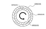
- the second pipe 60B has an inner diameter larger than the outer diameter of the first pipe 60A, and is fixed to each other with the first pipe 60A in a state where the first pipe 60A is inserted inside. Therefore, although there is actually a step at the boundary between the first pipe 60A and the second pipe 60B, the illustration is omitted in the examples shown in FIGS. 1 and 2.
- the difference between the outer diameter of the first pipe 60A and the inner diameter of the second pipe 60B is preferably 5 mm or less. This is because the pipes 60A and 60B can be fixed more firmly and firmly by setting the difference to 5 mm or less.
- the insertion amount of the first pipe 60A into the second pipe 60B is preferably 10 mm or more. This is because the pipes 60A and 60B can be more firmly and firmly fixed to each other by setting the insertion amount to 10 mm or more.
- overlap as used herein means that the end portion of the pipe 60A and the end portion of the pipe 60B overlap when viewed from the radial direction of the pipes 60A and 60B.
- the overlapping lengths referred to here indicate the distances measured along the axial directions of the pipes 60A and 60B.
- the outer peripheral surface of the first pipe 60A is subjected to diameter expansion processing.
- the portion subjected to the diameter expansion process is referred to as a “diameter expansion portion”.
- the enlarged diameter portion 60C is formed in the middle portion of the first pipe 60A.
- the enlarged diameter portion 60C is provided with a recess 60D recessed inward in the radial direction.
- a coil spring 60E having an elastic force in the axial direction is provided in the space inside the second pipe 60B.
- a protrusion 60F is provided on the inner peripheral surface of the second pipe 60B to allow the recess 60D to pass a predetermined distance (for example, 10 mm or more) against the elastic force of the coil spring 60E.
- the first frame assembly 60 is configured so that the second pipe 60B can rotate with respect to the first pipe 60A in a state where the second pipe 60B is inserted into the first pipe 60A by a predetermined distance (for example, 10 mm or more). (The direction indicated by the arrow in FIG. 4). As shown in FIG.
- the mounting unit 5 is, for example, a mechanism for mounting and holding a load (loading object) 51.
- the battery 50 may be loaded on the mounting unit 5.
- the mounting portion 5 is provided on the frame 4 and stores the luggage 51.
- the batteries 50 are arranged side by side in the X direction with the luggage 51 in between.
- the number of batteries 50 to be loaded is not particularly limited.
- the mounting portion 5 may have not only a square portion having V1 to V4 as vertices but also a square portion protruding from the square portion in the ⁇ Y direction.
- the mounting portion 5 may be fixed to the frame 4 so as not to rotate. Further, the mounting portion 5 may have a mechanism that can rotate with respect to the frame 4.
- the mounting portion 5 has a hinge (connecting portion) 52 that connects the housing of the mounting portion 5 and the frame 4.
- the hinge 52 as a fulcrum, the mounting portion 5 is configured to be rotatable in the pitch direction with respect to the frame 4.
- the limit of the angle at which the mounting portion 5 rotates with respect to the frame 4 via the hinge 52 is not particularly limited.
- the orientation of the mounting portion 5 so that the luggage 51 does not tilt even when the unmanned aerial vehicle 1 is hovering from the ground Gr in a backward leaning posture. Can be kept horizontal.
- the cargo 51 can be held in a stable state even during flight and delivered to the destination.
- the hinge 52 according to the present embodiment rotates the mounting portion 5 only in the front-rear direction (that is, the pitch direction), which is the same direction as the traveling direction.
- the hinge 52 may further rotate the mounting portion 5 in the left-right direction (roll direction and / or yaw direction).
- the hinge 52 may have a mechanism such as a gimbal that actively controls the posture of the mounting portion 5 by a motor or the like. This makes it possible to control the attitude of the mounting unit 5 during flight. Then, the wobbling (natural vibration, etc.) of the mounting portion 5 is further reduced, and the package 51 can be delivered more stably.
- the hinge 52 may be configured to be connected to the luggage 51 instead of the mounting portion 5. Further, the hinge 52 may not be provided.
- the shape and / or mechanism of the mounting portion 5 is not particularly limited as long as the luggage 51 can be stored and held. Further, the mechanism for holding the position or inclination of the luggage 51 mounted on the mounting portion 5 may be, for example, a tilt mechanism for tilting the luggage 51. Further, as described above, the mounting portion 5 does not necessarily have a structure that can rotate with respect to the frame 4.
- the unmanned aerial vehicle 1 in the present embodiment does not have landing gears in order to reduce the weight. Therefore, in the present embodiment, when the unmanned aerial vehicle 1 lands, the mounting unit 5 exerts the function of the landing gear.
- the frame 4 or the mounting portion 5 or the like may be provided with landing gears as appropriate.
- FIG. 6 is a side view showing the flight state of the unmanned aerial vehicle 1 during hovering according to the present embodiment.
- FIG. 7 is a side view showing the flight state of the unmanned aerial vehicle 1 during level flight according to the present embodiment.
- the unmanned aerial vehicle 1 takes a backward leaning posture so that the lift obtained by the rotary blade 2 is upward.
- the frame 4 becomes horizontal, and the rotation axis RA of the rotor 2 faces in the Y-axis direction and diagonally upward.
- the lift obtained from the rotor 2 is composed of a front component and an upper component.
- the unmanned aerial vehicle 1 can move in the horizontal direction while keeping the posture of the mounting portion 5 horizontal in the air.
- the flight mode of the unmanned aerial vehicle 1 according to the present embodiment is not limited to the examples shown in FIGS. 5 to 7.
- the unmanned aerial vehicle 1 in the hovering state of the unmanned aerial vehicle 1, the unmanned aerial vehicle 1 is in a horizontal position, and in the horizontal flight of the unmanned aerial vehicle 1, the unmanned aerial vehicle 1 is in a forward leaning position with respect to the cruising direction. good.
- a flight mode can be appropriately adjusted according to a configuration mode such as a frame 4 and a rotary wing 2 constituting the unmanned aerial vehicle 1.
- a joint structure that allows the frame to be folded vertically is installed in order to solve the problem of making the airframe shrinkable.
- the installation of such a joint structure is one of the factors that hinder the weight reduction of the airframe, and the manufacturing cost tends to be high.
- the second pipe 60B (second pipe 61B) can be obtained by simply inserting and removing the second pipe 60B (second pipe 61B) into and from the first pipe 60A (first pipe 61A). Is removable from the first pipe 60A (first pipe 61A). Therefore, in the configuration according to the present embodiment, a joint structure in which the frame can be folded becomes unnecessary. That is, according to the configuration according to the present embodiment, it is possible to provide the frame assembly 6 which is lightweight, can be reduced in size, and has a low manufacturing cost, and the unmanned aerial vehicle 1 provided with the frame assembly 6.
- the first pipe 60A of the second pipe 60B is inserted and removed.
- the reproducibility of positioning with respect to (first pipe 61A) is ensured.
- the length of the first frame assembly 60 (second frame assembly 61) is maintained at the same length each time. Therefore, the attitude of the unmanned aerial vehicle 1 is always kept symmetrical, and the balance of the unmanned aerial vehicle 1 during flight can be kept stable.
- the above-mentioned unmanned aerial vehicle 1 has, for example, the functional block shown in FIG.
- the functional block in FIG. 8 has a minimum reference configuration. Therefore, the functional block of the unmanned aerial vehicle 1 according to the present embodiment is not limited to such an example.
- the flight controller is a so-called processing unit.
- the processing unit can have one or more processors such as a programmable processor (eg, a central processing unit (CPU)).
- the processing unit has a memory (not shown), and the memory can be accessed.
- Memory stores logic, code, and / or program instructions that a processing unit can execute to perform one or more steps.
- the memory may include, for example, a separable medium such as an SD card or random access memory (RAM) or an external storage device.
- the data acquired from the cameras or sensors may be transmitted and stored directly in the memory. For example, still image / moving image data taken by a camera or the like is recorded in an internal memory or an external memory.
- the processing unit includes a control module configured to control the state of the unmanned aerial vehicle 1.
- the control module adjusts the spatial arrangement, velocity, and / or acceleration of the unmanned aerial vehicle 1 with 6 degrees of freedom (translational motion x, y and z, and rotational motion ⁇ x , ⁇ y and ⁇ z).
- the control module can control one or more of the states of the mounting unit 5 and the sensors.
- the processing unit is capable of communicating with a transmitter / receiver configured to transmit and / or receive data from one or more external devices (eg, terminals, display devices, or other remote controls).
- the transceiver can use any suitable communication means such as wired communication or wireless communication.
- the transmitter / receiver uses one or more of local area network (LAN), wide area network (WAN), infrared, wireless, WiFi, point-to-point (P2P) network, telecommunications network, cloud communication, and the like. be able to.
- the transmitter / receiver can transmit and / or receive one or more of the data acquired by the sensors, the processing result generated by the processing unit, the predetermined control data, the user command from the terminal or the remote controller, and the like. ..
- the sensors according to this embodiment may include an inertial sensor (acceleration sensor, gyro sensor), GPS sensor, proximity sensor (eg, rider), or vision / image sensor (eg, camera).
- inertial sensor acceleration sensor, gyro sensor
- GPS sensor GPS sensor
- proximity sensor eg, rider
- vision / image sensor eg, camera
- the unmanned aerial vehicle frame assembly disclosed in the present disclosure and the unmanned aerial vehicle equipped with the frame assembly can be expected to be used as an unmanned aerial vehicle for logistics and as an industrial unmanned aerial vehicle in a warehouse or a factory.
- the unmanned aerial vehicle of the present disclosure can be used in airplane-related industries such as multicopter drones.
- the present disclosure can be suitably used as an unmanned aerial vehicle for aerial photography equipped with a camera or the like.
- the technology can also be used in various industries such as security, agriculture, and infrastructure monitoring.
- the fixing method is not limited to this.
- the fixing method may be, for example, press-fitting, screwing, screwing, welding, adhesion, caulking by plastic deformation, magnetic bonding, or other types of fixing methods.
- a recess 60D (recess 61D) is provided in the first pipe 60A (first pipe 61A), and a protrusion 60F (protrusion) is provided in the second pipe 60B (second pipe 61B).
- An example of providing 61F) is shown.
- the method of fixing the pipes to each other is not limited to this, and may be reversed.
- the frame 4 is attached to the end of the first pipe 60A and the motor mount 31 is attached to the end of the second pipe 60B.
- the present invention is not limited to this, and the motor mount 31 may be attached to the end of the first pipe 60A, and the frame 4 may be attached to the end of the second pipe 60B.
- Unmanned aerial vehicle Rotorcraft (lift generator) 3 Motor 31 Motor mount (support) 4 frames (main body) 5 Mounting part 51 Luggage (loading object) 52 Hinge (connection part) 6 Frame assembly 60 1st frame assembly 61 2nd frame assembly 60A, 61A 1st pipe 60B, 61B 2nd pipe 60C, 61C Enlarged diameter portion 60D, 61D Recess 60E, 61E Coil spring 60F, 61F Protrusion
Landscapes
- Engineering & Computer Science (AREA)
- Remote Sensing (AREA)
- Mechanical Engineering (AREA)
- Aviation & Aerospace Engineering (AREA)
- Chemical & Material Sciences (AREA)
- Composite Materials (AREA)
- Materials Engineering (AREA)
- Toys (AREA)
Priority Applications (3)
| Application Number | Priority Date | Filing Date | Title |
|---|---|---|---|
| PCT/JP2020/018077 WO2021220390A1 (ja) | 2020-04-28 | 2020-04-28 | 無人航空機用フレーム組立体及びこれを備える無人航空機 |
| JP2022518477A JP7540764B2 (ja) | 2020-04-28 | 2020-04-28 | 無人航空機用フレーム組立体及びこれを備える無人航空機 |
| JP2024129739A JP7779566B2 (ja) | 2020-04-28 | 2024-08-06 | 無人航空機用フレーム組立体及びこれを備える無人航空機 |
Applications Claiming Priority (1)
| Application Number | Priority Date | Filing Date | Title |
|---|---|---|---|
| PCT/JP2020/018077 WO2021220390A1 (ja) | 2020-04-28 | 2020-04-28 | 無人航空機用フレーム組立体及びこれを備える無人航空機 |
Publications (1)
| Publication Number | Publication Date |
|---|---|
| WO2021220390A1 true WO2021220390A1 (ja) | 2021-11-04 |
Family
ID=78373448
Family Applications (1)
| Application Number | Title | Priority Date | Filing Date |
|---|---|---|---|
| PCT/JP2020/018077 Ceased WO2021220390A1 (ja) | 2020-04-28 | 2020-04-28 | 無人航空機用フレーム組立体及びこれを備える無人航空機 |
Country Status (2)
| Country | Link |
|---|---|
| JP (2) | JP7540764B2 (https=) |
| WO (1) | WO2021220390A1 (https=) |
Cited By (1)
| Publication number | Priority date | Publication date | Assignee | Title |
|---|---|---|---|---|
| CN112520026A (zh) * | 2020-12-23 | 2021-03-19 | 中国民用航空飞行学院 | 一种新型变体飞行器 |
Citations (3)
| Publication number | Priority date | Publication date | Assignee | Title |
|---|---|---|---|---|
| CN208036608U (zh) * | 2018-01-17 | 2018-11-02 | 南安市奕圣科技有限公司 | 一种具备反制无人机功能的特种无人机 |
| CN209064359U (zh) * | 2018-09-28 | 2019-07-05 | 深圳市大疆创新科技有限公司 | 机臂组件及包括该机臂组件的无人机 |
| CN209241303U (zh) * | 2018-12-18 | 2019-08-13 | 辽宁壮龙无人机科技有限公司 | 一种旋翼无人机的机臂及无人机 |
Family Cites Families (2)
| Publication number | Priority date | Publication date | Assignee | Title |
|---|---|---|---|---|
| JP2005329133A (ja) | 2004-05-21 | 2005-12-02 | Akiko Kawashima | 連結具 |
| CN107651182B (zh) * | 2017-09-25 | 2020-08-18 | 湖南山河科技股份有限公司 | 一种多功能便携式多旋翼无人机 |
-
2020
- 2020-04-28 JP JP2022518477A patent/JP7540764B2/ja active Active
- 2020-04-28 WO PCT/JP2020/018077 patent/WO2021220390A1/ja not_active Ceased
-
2024
- 2024-08-06 JP JP2024129739A patent/JP7779566B2/ja active Active
Patent Citations (3)
| Publication number | Priority date | Publication date | Assignee | Title |
|---|---|---|---|---|
| CN208036608U (zh) * | 2018-01-17 | 2018-11-02 | 南安市奕圣科技有限公司 | 一种具备反制无人机功能的特种无人机 |
| CN209064359U (zh) * | 2018-09-28 | 2019-07-05 | 深圳市大疆创新科技有限公司 | 机臂组件及包括该机臂组件的无人机 |
| CN209241303U (zh) * | 2018-12-18 | 2019-08-13 | 辽宁壮龙无人机科技有限公司 | 一种旋翼无人机的机臂及无人机 |
Cited By (1)
| Publication number | Priority date | Publication date | Assignee | Title |
|---|---|---|---|---|
| CN112520026A (zh) * | 2020-12-23 | 2021-03-19 | 中国民用航空飞行学院 | 一种新型变体飞行器 |
Also Published As
| Publication number | Publication date |
|---|---|
| JP7779566B2 (ja) | 2025-12-03 |
| JPWO2021220390A1 (https=) | 2021-11-04 |
| JP2024149702A (ja) | 2024-10-18 |
| JP7540764B2 (ja) | 2024-08-27 |
Similar Documents
| Publication | Publication Date | Title |
|---|---|---|
| JP7726552B2 (ja) | 飛行体 | |
| CN104508346B (zh) | 非正交轴载体 | |
| JP6613424B1 (ja) | 飛行体の飛行方法 | |
| JP6952389B1 (ja) | 飛行体 | |
| JP6664822B1 (ja) | 飛行体 | |
| US12084209B2 (en) | Rotorcraft | |
| JP7779566B2 (ja) | 無人航空機用フレーム組立体及びこれを備える無人航空機 | |
| US12246828B2 (en) | Aerial vehicle having a first wing and a second wing that tilt and rotate to form an inverted V-shape | |
| US20230013275A1 (en) | Takeoff and landing system | |
| JP6618000B1 (ja) | 電子部品及び当該電子部品を取り付けた飛行体 | |
| WO2021074986A1 (ja) | 飛行体 | |
| JP6993711B2 (ja) | 飛行体及び飛行体の飛行方法 | |
| JP2021049965A (ja) | 飛行体 | |
| US20220297834A1 (en) | Flying body | |
| JP2021062860A (ja) | 飛行体 | |
| JP7244955B2 (ja) | 飛行体及び飛行体の飛行方法 | |
| JP2022075257A (ja) | アタッチメント及び飛行体 | |
| WO2021059323A1 (ja) | アタッチメント及び飛行体 | |
| WO2021024370A1 (ja) | 飛行体 | |
| WO2021070363A1 (ja) | 飛行体 | |
| JP2020152378A (ja) | 飛行体及び飛行体の飛行方法 | |
| JPWO2020021650A1 (ja) | プロペラ、モータ部品及びこれを備えた飛行体 |
Legal Events
| Date | Code | Title | Description |
|---|---|---|---|
| 121 | Ep: the epo has been informed by wipo that ep was designated in this application |
Ref document number: 20934107 Country of ref document: EP Kind code of ref document: A1 |
|
| ENP | Entry into the national phase |
Ref document number: 2022518477 Country of ref document: JP Kind code of ref document: A |
|
| NENP | Non-entry into the national phase |
Ref country code: DE |
|
| 122 | Ep: pct application non-entry in european phase |
Ref document number: 20934107 Country of ref document: EP Kind code of ref document: A1 |