WO2021215543A1 - インプラント用マグネシウム合金、骨固定具、インプラント用マグネシウム合金の製造方法及び骨固定具の製造方法 - Google Patents
インプラント用マグネシウム合金、骨固定具、インプラント用マグネシウム合金の製造方法及び骨固定具の製造方法 Download PDFInfo
- Publication number
- WO2021215543A1 WO2021215543A1 PCT/JP2021/016870 JP2021016870W WO2021215543A1 WO 2021215543 A1 WO2021215543 A1 WO 2021215543A1 JP 2021016870 W JP2021016870 W JP 2021016870W WO 2021215543 A1 WO2021215543 A1 WO 2021215543A1
- Authority
- WO
- WIPO (PCT)
- Prior art keywords
- magnesium alloy
- implants
- alloy
- atomic
- producing
- Prior art date
- Legal status (The legal status is an assumption and is not a legal conclusion. Google has not performed a legal analysis and makes no representation as to the accuracy of the status listed.)
- Ceased
Links
Images




Classifications
-
- A—HUMAN NECESSITIES
- A61—MEDICAL OR VETERINARY SCIENCE; HYGIENE
- A61L—METHODS OR APPARATUS FOR STERILISING MATERIALS OR OBJECTS IN GENERAL; DISINFECTION, STERILISATION OR DEODORISATION OF AIR; CHEMICAL ASPECTS OF BANDAGES, DRESSINGS, ABSORBENT PADS OR SURGICAL ARTICLES; MATERIALS FOR BANDAGES, DRESSINGS, ABSORBENT PADS OR SURGICAL ARTICLES
- A61L27/00—Materials for grafts or prostheses or for coating grafts or prostheses
- A61L27/02—Inorganic materials
- A61L27/04—Metals or alloys
- A61L27/047—Other specific metals or alloys not covered by A61L27/042 - A61L27/045 or A61L27/06
-
- A—HUMAN NECESSITIES
- A61—MEDICAL OR VETERINARY SCIENCE; HYGIENE
- A61L—METHODS OR APPARATUS FOR STERILISING MATERIALS OR OBJECTS IN GENERAL; DISINFECTION, STERILISATION OR DEODORISATION OF AIR; CHEMICAL ASPECTS OF BANDAGES, DRESSINGS, ABSORBENT PADS OR SURGICAL ARTICLES; MATERIALS FOR BANDAGES, DRESSINGS, ABSORBENT PADS OR SURGICAL ARTICLES
- A61L27/00—Materials for grafts or prostheses or for coating grafts or prostheses
- A61L27/02—Inorganic materials
- A61L27/04—Metals or alloys
-
- A—HUMAN NECESSITIES
- A61—MEDICAL OR VETERINARY SCIENCE; HYGIENE
- A61L—METHODS OR APPARATUS FOR STERILISING MATERIALS OR OBJECTS IN GENERAL; DISINFECTION, STERILISATION OR DEODORISATION OF AIR; CHEMICAL ASPECTS OF BANDAGES, DRESSINGS, ABSORBENT PADS OR SURGICAL ARTICLES; MATERIALS FOR BANDAGES, DRESSINGS, ABSORBENT PADS OR SURGICAL ARTICLES
- A61L27/00—Materials for grafts or prostheses or for coating grafts or prostheses
- A61L27/50—Materials characterised by their function or physical properties, e.g. injectable or lubricating compositions, shape-memory materials, surface modified materials
- A61L27/58—Materials at least partially resorbable by the body
-
- A—HUMAN NECESSITIES
- A61—MEDICAL OR VETERINARY SCIENCE; HYGIENE
- A61L—METHODS OR APPARATUS FOR STERILISING MATERIALS OR OBJECTS IN GENERAL; DISINFECTION, STERILISATION OR DEODORISATION OF AIR; CHEMICAL ASPECTS OF BANDAGES, DRESSINGS, ABSORBENT PADS OR SURGICAL ARTICLES; MATERIALS FOR BANDAGES, DRESSINGS, ABSORBENT PADS OR SURGICAL ARTICLES
- A61L31/00—Materials for other surgical articles, e.g. stents, stent-grafts, shunts, surgical drapes, guide wires, materials for adhesion prevention, occluding devices, surgical gloves, tissue fixation devices
- A61L31/02—Inorganic materials
- A61L31/022—Metals or alloys
-
- A—HUMAN NECESSITIES
- A61—MEDICAL OR VETERINARY SCIENCE; HYGIENE
- A61L—METHODS OR APPARATUS FOR STERILISING MATERIALS OR OBJECTS IN GENERAL; DISINFECTION, STERILISATION OR DEODORISATION OF AIR; CHEMICAL ASPECTS OF BANDAGES, DRESSINGS, ABSORBENT PADS OR SURGICAL ARTICLES; MATERIALS FOR BANDAGES, DRESSINGS, ABSORBENT PADS OR SURGICAL ARTICLES
- A61L31/00—Materials for other surgical articles, e.g. stents, stent-grafts, shunts, surgical drapes, guide wires, materials for adhesion prevention, occluding devices, surgical gloves, tissue fixation devices
- A61L31/14—Materials characterised by their function or physical properties, e.g. injectable or lubricating compositions, shape-memory materials, surface modified materials
- A61L31/148—Materials at least partially resorbable by the body
-
- B—PERFORMING OPERATIONS; TRANSPORTING
- B21—MECHANICAL METAL-WORKING WITHOUT ESSENTIALLY REMOVING MATERIAL; PUNCHING METAL
- B21C—MANUFACTURE OF METAL SHEETS, WIRE, RODS, TUBES, PROFILES OR LIKE SEMI-MANUFACTURED PRODUCTS OTHERWISE THAN BY ROLLING; AUXILIARY OPERATIONS USED IN CONNECTION WITH METAL-WORKING WITHOUT ESSENTIALLY REMOVING MATERIAL
- B21C23/00—Extruding metal; Impact extrusion
- B21C23/001—Extruding metal; Impact extrusion to improve the material properties, e.g. lateral extrusion
-
- B—PERFORMING OPERATIONS; TRANSPORTING
- B21—MECHANICAL METAL-WORKING WITHOUT ESSENTIALLY REMOVING MATERIAL; PUNCHING METAL
- B21C—MANUFACTURE OF METAL SHEETS, WIRE, RODS, TUBES, PROFILES OR LIKE SEMI-MANUFACTURED PRODUCTS OTHERWISE THAN BY ROLLING; AUXILIARY OPERATIONS USED IN CONNECTION WITH METAL-WORKING WITHOUT ESSENTIALLY REMOVING MATERIAL
- B21C23/00—Extruding metal; Impact extrusion
- B21C23/002—Extruding materials of special alloys so far as the composition of the alloy requires or permits special extruding methods of sequences
-
- B—PERFORMING OPERATIONS; TRANSPORTING
- B21—MECHANICAL METAL-WORKING WITHOUT ESSENTIALLY REMOVING MATERIAL; PUNCHING METAL
- B21C—MANUFACTURE OF METAL SHEETS, WIRE, RODS, TUBES, PROFILES OR LIKE SEMI-MANUFACTURED PRODUCTS OTHERWISE THAN BY ROLLING; AUXILIARY OPERATIONS USED IN CONNECTION WITH METAL-WORKING WITHOUT ESSENTIALLY REMOVING MATERIAL
- B21C29/00—Cooling or heating extruded work or parts of the extrusion press
- B21C29/003—Cooling or heating of work
-
- B—PERFORMING OPERATIONS; TRANSPORTING
- B22—CASTING; POWDER METALLURGY
- B22F—WORKING METALLIC POWDER; MANUFACTURE OF ARTICLES FROM METALLIC POWDER; MAKING METALLIC POWDER; APPARATUS OR DEVICES SPECIALLY ADAPTED FOR METALLIC POWDER
- B22F1/00—Metallic powder; Treatment of metallic powder, e.g. to facilitate working or to improve properties
- B22F1/06—Metallic powder characterised by the shape of the particles
- B22F1/068—Flake-like particles
-
- B—PERFORMING OPERATIONS; TRANSPORTING
- B22—CASTING; POWDER METALLURGY
- B22F—WORKING METALLIC POWDER; MANUFACTURE OF ARTICLES FROM METALLIC POWDER; MAKING METALLIC POWDER; APPARATUS OR DEVICES SPECIALLY ADAPTED FOR METALLIC POWDER
- B22F3/00—Manufacture of workpieces or articles from metallic powder characterised by the manner of compacting or sintering; Apparatus specially adapted therefor ; Presses and furnaces
- B22F3/20—Manufacture of workpieces or articles from metallic powder characterised by the manner of compacting or sintering; Apparatus specially adapted therefor ; Presses and furnaces by extruding
-
- B—PERFORMING OPERATIONS; TRANSPORTING
- B22—CASTING; POWDER METALLURGY
- B22F—WORKING METALLIC POWDER; MANUFACTURE OF ARTICLES FROM METALLIC POWDER; MAKING METALLIC POWDER; APPARATUS OR DEVICES SPECIALLY ADAPTED FOR METALLIC POWDER
- B22F9/00—Making metallic powder or suspensions thereof
- B22F9/02—Making metallic powder or suspensions thereof using physical processes
- B22F9/06—Making metallic powder or suspensions thereof using physical processes starting from liquid material
- B22F9/08—Making metallic powder or suspensions thereof using physical processes starting from liquid material by casting, e.g. through sieves or in water, by atomising or spraying
- B22F9/10—Making metallic powder or suspensions thereof using physical processes starting from liquid material by casting, e.g. through sieves or in water, by atomising or spraying using centrifugal force
-
- C—CHEMISTRY; METALLURGY
- C22—METALLURGY; FERROUS OR NON-FERROUS ALLOYS; TREATMENT OF ALLOYS OR NON-FERROUS METALS
- C22C—ALLOYS
- C22C1/00—Making non-ferrous alloys
- C22C1/02—Making non-ferrous alloys by melting
-
- C—CHEMISTRY; METALLURGY
- C22—METALLURGY; FERROUS OR NON-FERROUS ALLOYS; TREATMENT OF ALLOYS OR NON-FERROUS METALS
- C22C—ALLOYS
- C22C1/00—Making non-ferrous alloys
- C22C1/04—Making non-ferrous alloys by powder metallurgy
- C22C1/0408—Light metal alloys
-
- C—CHEMISTRY; METALLURGY
- C22—METALLURGY; FERROUS OR NON-FERROUS ALLOYS; TREATMENT OF ALLOYS OR NON-FERROUS METALS
- C22C—ALLOYS
- C22C23/00—Alloys based on magnesium
- C22C23/04—Alloys based on magnesium with zinc or cadmium as the next major constituent
-
- C—CHEMISTRY; METALLURGY
- C22—METALLURGY; FERROUS OR NON-FERROUS ALLOYS; TREATMENT OF ALLOYS OR NON-FERROUS METALS
- C22F—CHANGING THE PHYSICAL STRUCTURE OF NON-FERROUS METALS AND NON-FERROUS ALLOYS
- C22F1/00—Changing the physical structure of non-ferrous metals or alloys by heat treatment or by hot or cold working
- C22F1/06—Changing the physical structure of non-ferrous metals or alloys by heat treatment or by hot or cold working of magnesium or alloys based thereon
-
- A—HUMAN NECESSITIES
- A61—MEDICAL OR VETERINARY SCIENCE; HYGIENE
- A61L—METHODS OR APPARATUS FOR STERILISING MATERIALS OR OBJECTS IN GENERAL; DISINFECTION, STERILISATION OR DEODORISATION OF AIR; CHEMICAL ASPECTS OF BANDAGES, DRESSINGS, ABSORBENT PADS OR SURGICAL ARTICLES; MATERIALS FOR BANDAGES, DRESSINGS, ABSORBENT PADS OR SURGICAL ARTICLES
- A61L2430/00—Materials or treatment for tissue regeneration
- A61L2430/02—Materials or treatment for tissue regeneration for reconstruction of bones; weight-bearing implants
-
- B—PERFORMING OPERATIONS; TRANSPORTING
- B22—CASTING; POWDER METALLURGY
- B22F—WORKING METALLIC POWDER; MANUFACTURE OF ARTICLES FROM METALLIC POWDER; MAKING METALLIC POWDER; APPARATUS OR DEVICES SPECIALLY ADAPTED FOR METALLIC POWDER
- B22F2998/00—Supplementary information concerning processes or compositions relating to powder metallurgy
- B22F2998/10—Processes characterised by the sequence of their steps
-
- B—PERFORMING OPERATIONS; TRANSPORTING
- B22—CASTING; POWDER METALLURGY
- B22F—WORKING METALLIC POWDER; MANUFACTURE OF ARTICLES FROM METALLIC POWDER; MAKING METALLIC POWDER; APPARATUS OR DEVICES SPECIALLY ADAPTED FOR METALLIC POWDER
- B22F3/00—Manufacture of workpieces or articles from metallic powder characterised by the manner of compacting or sintering; Apparatus specially adapted therefor ; Presses and furnaces
- B22F3/22—Manufacture of workpieces or articles from metallic powder characterised by the manner of compacting or sintering; Apparatus specially adapted therefor ; Presses and furnaces for producing castings from a slip
- B22F3/225—Manufacture of workpieces or articles from metallic powder characterised by the manner of compacting or sintering; Apparatus specially adapted therefor ; Presses and furnaces for producing castings from a slip by injection molding
Definitions
- the present invention relates to a magnesium alloy for implants, a bone fixture, a method for producing a magnesium alloy for implants, and a method for producing a bone fixture.
- Stainless steel and titanium alloys are used for bone fixtures (plates, screws, etc.) used to treat fractures. Since these alloys are not absorbed into the body, they will remain permanently in the body unless the bone fixture is removed by reoperation. Therefore, it is desired that the material of the bone fixture has a property of being absorbed by a living body and a biocompatibility.
- Polylactic acid and magnesium alloys have been put into practical use as materials having bioabsorbability and biocompatibility. A technique related thereto is disclosed in Patent Document 1.
- polylactic acid is a polymer in which lactic acid is polymerized by an ester bond and is linked for a long time.
- polylactic acid has insufficient mechanical strength for use as a bone fixture.
- the magnesium alloy does not have sufficient corrosion resistance to be used as a bone fixture, and its mechanical strength is also insufficient.
- One aspect of the present invention is to provide a magnesium alloy for implants, a bone fixture, a method for producing a magnesium alloy for implants, or a method for producing a bone fixture, which has both corrosion resistance and mechanical strength.
- x and y are magnesium alloys for implants, which satisfy the following (formula 1) and (formula 2).
- Equation 1 0.15 ⁇ x ⁇ 1.5 (preferably 0.2 ⁇ x ⁇ 1.0)
- Equation 2 0.5 ⁇ y ⁇ 1.5 (preferably 0.75 ⁇ x ⁇ 1.25)
- the magnesium alloy contains a atomic% of Mn, and a is a magnesium alloy for implants, which satisfies the following (formula 3).
- Equation 3) 0.01 ⁇ a ⁇ 0.08 (preferably 0.02 ⁇ a ⁇ 0.05) [3]
- the magnesium alloy contains z atomic% of RE (rare earth element), and z is a magnesium alloy for implants, which satisfies the following (formula 4).
- the magnesium alloy has a plurality of ⁇ -Mg particles and has a plurality of ⁇ -Mg particles.
- a magnesium alloy for implants wherein the average particle size of the plurality of ⁇ -Mg particles is 0.8 ⁇ m or more and 2.5 ⁇ m or less (preferably 1.0 ⁇ m or more and 2.0 ⁇ m or less).
- the magnesium alloy is a magnesium alloy for implants, which comprises at least one compound of Mg 2 Ca and Mg 17 Sr 2.
- a magnesium alloy for implants wherein the average particle size of the at least one compound is 0.07 ⁇ m or more and 0.29 ⁇ m or less (preferably 0.09 ⁇ m or more and 0.25 ⁇ m or less).
- the magnesium alloy is a magnesium alloy for implants, which does not contain a compound of Mg 6 Ca 2 Zn 3 in the constituent phase determined by X-ray diffraction.
- the magnesium alloy for implants is characterized by containing no unavoidable amount of Al or more.
- a bone fixture comprising the magnesium alloy for implant according to any one of the above [1] to [8].
- the magnesium alloy contains x atomic% of Zn, contains y atomic% of at least one element of Ca and Sr, and is composed of a magnesium alloy having the balance of Mg and unavoidable impurities.
- Equation 3 0.01 ⁇ a ⁇ 0.08 (preferably 0.02 ⁇ a ⁇ 0.05) [13]
- the magnesium alloy contains z atomic% of RE (rare earth element), and z satisfies the following (formula 4), which is a method for producing a magnesium alloy for implants.
- Equation 4 0 ⁇ z ⁇ 0.2 (preferably 0 ⁇ z ⁇ 0.1) [14]
- the rapid solidified product or the solidified molded product has a plurality of ⁇ -Mg particles and has a plurality of ⁇ -Mg particles.
- a magnesium alloy for implants wherein the average particle size of the plurality of ⁇ -Mg particles is 0.8 ⁇ m or more and 2.5 ⁇ m or less (preferably 1.0 ⁇ m or more and 2.0 ⁇ m or less).
- a method for producing a magnesium alloy for implants wherein the rapidly coagulated product or the solidified molded product contains at least one compound of Mg 2 Ca and Mg 17 Sr 2.
- a method for producing a magnesium alloy for implants wherein the average particle size of the at least one compound is 0.07 ⁇ m or more and 0.29 ⁇ m or less (preferably 0.09 ⁇ m or more and 0.25 ⁇ m or less).
- a method for producing a magnesium alloy for implants wherein the rapidly coagulated product or the solidified molded product does not contain a compound of Mg 6 Ca 2 Zn 3 in the constituent phase determined by X-ray diffraction.
- a method for producing a magnesium alloy for implants wherein the magnesium alloy does not contain more than an unavoidable amount of Al.
- a method for producing a bone fixture which comprises a step of manufacturing a bone fixture using the magnesium alloy for implant according to any one of the above [10] to [18]. According to one aspect of the present invention, it is possible to provide a magnesium alloy for implants, a bone fixture, a method for producing a magnesium alloy for implants, or a method for producing a bone fixture, which has both corrosion resistance and mechanical strength.
- FIG. 1 is a schematic diagram of an equipment system for producing rapidly solidified magnesium alloy flakes using a single roll liquid quenching method.
- FIG. 2 is a diagram showing the dependence of the proof stress ⁇ YS and the elongation ⁇ on the amount of Zn added in the rapid solidification thin band solidification molding Mg 99-x Ca 1 Zn x alloy according to Examples 1 to 3 and Comparative Examples 1 to 3.
- FIG. 3 is a diagram showing the Zn addition amount dependence of the corrosion rate in the simulated body fluid of the rapid solidification thin band solidification molded Mg 99-x Ca 1 Zn x alloy according to Examples 1 to 3 and Comparative Examples 1 to 3.
- FIG. 1 is a schematic diagram of an equipment system for producing rapidly solidified magnesium alloy flakes using a single roll liquid quenching method.
- FIG. 2 is a diagram showing the dependence of the proof stress ⁇ YS and the elongation ⁇ on the amount of Zn added in the rapid solidification thin band solidification molding Mg 99-x Ca 1 Zn
- FIG. 5 is a diagram showing the extrusion temperature dependence of the rapid solidification thin band solidification molding Mg 98.5 Ca 1 Zn 0.5 alloy according to Examples 3 to 7 during solidification molding with the proof stress ⁇ YS and the elongation ⁇ .
- FIG. 5 is a diagram showing the extrusion temperature dependence of the rapid solidification thin band solidification molding Mg 98.5 Ca 1 Zn 0.5 alloy according to Examples 3 to 7 during solidification molding with the proof stress ⁇ YS and the elongation ⁇ .
- FIG. 8 is an organizational chart showing the particle size distribution and crystal orientation when the rapidly solidified thin band solidified Mg 98.5 Ca 1 Zn 0.5 alloy of Example 3 was measured by EBSD.
- FIG. 8 is an organizational chart showing the particle size distribution and crystal orientation when the rapidly solidified thin band solidified Mg 98.5 Ca 1 Zn 0.5 alloy of Example 3 was measured by EBSD.
- FIG. 10 shows the rapid solidification thin band solidification molding Mg 98.5 Ca 1 Zn 0.5 alloy of Example 3, and the rapid solidification thin band solidification molding Mg 98.5 Ca 0.5 Sr 0.5 Zn 0 of Example 9.
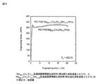
- FIG. 11 is a diagram showing the proof stress ⁇ YS and the elongation ⁇ of the alloys of Examples 3, 8 and 10 and the alloys of Examples 12 and 13 and Comparative Example 8 in which Y was added to each of the alloys.
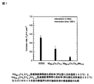
- FIG. 12 is a bar graph showing the corrosion rates of the alloys of Examples 3, 8 and 10 and the alloys of Examples 12 and 13 and Comparative Example 8 in which Y was added to each of the alloys in the simulated body fluid.
- FIG. 11 is a diagram showing the proof stress ⁇ YS and the elongation ⁇ of the alloys of Examples 3, 8 and 10 and the alloys of Examples 12 and 13 and Comparative Example 8 in which Y was added to each of the alloys.
- FIG. 12 is a bar graph showing the corrosion rates of the alloys of Examples 3, 8 and 10 and the alloys of Examples 12 and 13 and Comparative Example 8 in which Y was added to each of the alloys in the simulated body fluid.
- FIG. 13 is a diagram showing an X-ray diffraction pattern (XRD) of each of the cast extruded materials of Comparative Examples 4, 5 and 6.
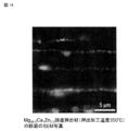
- FIG. 14 is an SEM photograph of a cross section of the Mg 98.5 Ca 1 Zn 0.5 cast extruded material (extrusion processing temperature 350 ° C.) of Comparative Example 5.
- Bone fixtures include plates, screws, clips and bolts used to treat fractures.
- This bone fixture is preferably formed from a magnesium alloy for implants, which has a property of being absorbed by a living body and has a biocompatibility.
- the magnesium alloy for implants does not contain Al or Ni, which is harmful to the living body, and may contain Ca or the like, which promotes bone tissue regeneration.
- the magnesium alloy for implants according to one aspect of the present invention is an alloy containing x atomic% of Zn, y atomic% in total of at least one element of Ca and Sr, and the balance consisting of Mg and unavoidable impurities. .. It is preferable that x and y satisfy the following (Equation 1) and (Equation 2).
- Equation 1 0.15 ⁇ x ⁇ 1.5 (preferably 0.2 ⁇ x ⁇ 1.0)
- Equation 2 0.5 ⁇ y ⁇ 1.5 (preferably 0.75 ⁇ y ⁇ 1.25)
- Equation 1 0.15 ⁇ x ⁇ 1.5 (preferably 0.2 ⁇ x ⁇ 1.0)
- Equation 2 0.5 ⁇ y ⁇ 1.5 (preferably 0.75 ⁇ y ⁇ 1.25)
- Equation 1 0.15 ⁇ x ⁇ 1.5 (preferably 0.2 ⁇ x ⁇ 1.0)
- Equation 2 0.5 ⁇ y ⁇ 1.5 (preferably 0.75 ⁇ y ⁇ 1.25)
- the corrosion resistance is lowered and the corrosion rate in the simulated body liquid is higher than 0.7 mm / year, and even if the Zn content is less than 0.15 atomic%, the corrosion resistance is lowered and in the simulated body liquid.
- the corrosion rate of zinc is greater than 0.7 mm / year.
- the total content of y atomic% of at least one element of Ca and Sr means that Ca is contained in an amount of 0.5 atomic% or more and 1.5 atomic% or less, and Ca and Sr are contained in a total of 0. It means that it includes a case where it contains 5 atomic% or more and 1.5 atomic% or less and a case where it contains Sr at 0.5 atomic% or more and 1.5 atomic% or less.
- Ca has an effect of promoting the regeneration of bone tissue, but it is considered that even if Ca is replaced with Sr, the same effect is obtained.
- the reason why the Ca content range should satisfy the above formula 2 is that when the total content of Ca and Sr exceeds 1.5 atomic%, ductility and corrosion resistance decrease, and the total content of Ca and Sr is 0. If it is less than .5 atomic%, the effect of promoting the regeneration of bone tissue is not sufficiently obtained, and the corrosion resistance and the mechanical strength are lowered.
- the magnesium alloy for implants may further contain Mn in an atomic% of a, and a may satisfy the following (formula 3). By containing Mn, the corrosion rate in the body can be reduced.
- the magnesium alloy for implants may further contain RE (rare earth element) in z atomic%, and z may satisfy the following (formula 4).
- RE (rare earth element) is Y, La, Ce, Pr, Nd, Pm, Sm, Eu, Gd, Tb, Dy, Ho, Er, Tm, Yb, Lu.
- the reason why the content range of RE should satisfy the above formula 4 is that when RE is contained, the ignition temperature of the alloy is improved, and when the RE content exceeds 0.2 atomic%, ductility and corrosion resistance are lowered. It is in.
- the above magnesium alloy for implants has a plurality of ⁇ -Mg particles, and the average particle size of the plurality of ⁇ -Mg particles is 0.8 ⁇ m or more and 2.5 ⁇ m or less (preferably 1.0 ⁇ m or more and 2.0 ⁇ m or less). It would be nice to have it.
- the average particle size of the plurality of ⁇ -Mg grains exceeds 2.5 ⁇ m, the mechanical strength and corrosion resistance are lowered, and when the average particle size of the plurality of ⁇ -Mg grains is less than 0.8 ⁇ m, the ductility is lowered.
- the magnesium alloy for implants has at least one compound of Mg 2 Ca and Mg 17 Sr 2 , and the average particle size of the at least one compound is 0.07 ⁇ m or more and 0.29 ⁇ m or less (preferably 0.09 ⁇ m or more). 0.25 ⁇ m or less).
- the average particle size of at least one of the above compounds exceeds 0.29 ⁇ m, the corrosion resistance and mechanical strength are lowered, and when the average particle size of the plurality of ⁇ -Mg particles is less than 0.07 ⁇ m, the ductility is lowered.
- a magnesium alloy having the above-mentioned composition is melted at a high temperature to prepare a molten alloy, and the molten alloy is melted at 1 ⁇ 10 3 K / sec or more and 1 ⁇ 10 6 K / sec or less (preferably 1 ⁇ 10 4 K / sec or more).
- a plurality of rapid coagulants are produced by rapid coagulation at the cooling rate of the above, and powders, flakes, strips, fine wires, etc., which are the rapid coagulates thereof, are obtained.
- the obtained plurality of rapid solidified products are premolded, and then the molded products are plastically processed to produce a solidified molded product.
- the preforming may undergo a billet forming step by compressing powder, flakes, flakes or thin wires, or may be canning or the like.
- the pre-molding is for facilitating solidification molding, and has effects such as solidifying powder or the like to prevent oxidation during solidification molding and facilitating handling.
- the plastic working can also use hot extrusion, for example, an extrusion temperature of 275 to 425 ° C (preferably 300 ° C to 375 ° C), an extrusion pressure of 200 to 1000 MPa, and an extrusion ratio of 5 to 100 (preferably). It is preferable to carry out the operation under the conditions of 10 to 50) and a ram speed of 0.05 mm / sec or more.
- Rapid coagulation includes gun method, piston anvil method, centrifugation method, single roll method, double roll method, spray method, high pressure gas spray method, spinning in rotating liquid, thin plate molten metal injection molding method, etc.
- the method or high pressure gas spray method is particularly suitable.
- FIG. 1 is a schematic diagram of an equipment system for producing rapidly solidified magnesium alloy flakes using a single roll liquid quenching method. In the liquid quenching step using the single roll 11, first, the magnesium alloy for implant described above is melted by high frequency induction heating.
- homogenization is achieved by stirring the molten metal.
- the molten metal is sprayed by introducing an inert gas into the melting chamber 12 and the roll chamber 13 and controlling the differential pressure thereof.
- an inert gas into the melting chamber 12 and the roll chamber 13 and controlling the differential pressure thereof.
- the nozzle and crucible so that it can move up and down and back and forth and the tilt angle of the spray can be changed, it is possible to control the shape from triangular flakes to foil strips and thin strips, making it ideal for powder metallurgy processes. Rapidly solidified magnesium alloy flakes.
- the top and bottom are the gap distance between the roll 11 and the tip of the nozzle, and the front and back are the distance between the front and back from the roll core, and their range of motion is 0 to 50 mm, respectively.
- the maximum peripheral speed of the roll is 52 m / sec, and a rapid solidification microstructure is realized by high cooling in combination with water cooling.
- the cooling rate is 1 ⁇ 10 5 K / sec or more.
- the produced rapidly solidified magnesium alloy flakes have a plurality of ⁇ -Mg particles.
- the average particle size of the plurality of ⁇ -Mg particles at this stage is 10 ⁇ m or less.
- the average particle diameter is the average value of the particle diameter measured by using SEM and TEM.
- Mass-produced rapidly solidified magnesium alloy flakes are sorted and classified in an argon atmosphere glove box in the recovery process, then filled in copper or aluminum capsules, preformed by a press with an output of 1000 kN, and degassed into the capsules. Weld the attached lid (pre-molding process). Then, a valve is attached to the degassing tube, the mixture is taken out while maintaining the argon gas atmosphere inside the capsule, and vacuum degassing is performed with a turbo molecular pump while heating to a predetermined temperature (degassing step). After degassing, the degassing pipe is crimped, cut and welded to produce a billet (sealing process).
- the argon atmosphere glove box is also directly connected to the gas purification device, and by shutting off the single roll liquid quenching device side with a gate valve, the rapidly solidified magnesium alloy flakes can be made into billets without being exposed to the atmosphere at all. Can be done. Then, the billet is solidified by extrusion molding at an extrusion temperature of 275 ° C. to 425 ° C., a ram speed of 0.05 mm / sec or more, and an extrusion ratio of 5 to 100. This extrusion applies pressure and shear to the magnesium alloy flakes to achieve densification and bonding between the flakes. Shearing also occurs in molding by the rolling method or the forging method.
- the rapidly solidified thin band solidified molded product (magnesium alloy for implants) obtained by the solidification molding has a plurality of ⁇ -Mg grains, and the average particle size of these ⁇ -Mg grains is 0.8 ⁇ m or more and 2.5 ⁇ m. It has a fine crystal structure of the following (preferably 1.0 ⁇ m or more and 2.0 ⁇ m or less). Further, this solidified molded product contains at least one compound of Mg 2 Ca and Mg 17 Sr 2 , and the average particle size of the at least one compound is 0.07 ⁇ m or more and 0.29 ⁇ m or less (preferably 0.09 ⁇ m or more and 0). .25 ⁇ m or less).
- a fine and isotropic structure can be obtained in the rapidly solidified thin band solidified molded product produced by rapid solidification in this way, the anisotropy of the strength of the rapidly solidified thin band solidified molded product can be reduced.
- a work piece may be produced by extruding, rolling or forging the above-mentioned rapidly solidified thin band solidified molded product.
- the above magnesium alloy for implants can also be used for bioabsorbable medical devices other than the above bone fixtures.
- a molten magnesium alloy is rapidly coagulated to prepare a rapidly coagulated product, and the rapidly coagulated product is used to prepare a magnesium alloy for implants. Therefore, the average particle size of ⁇ -Mg grains is 2.5 ⁇ m or less. It can be as small as (preferably 2.0 ⁇ m or less). As a result, both the corrosion resistance and the mechanical strength and ductility of the magnesium alloy for implants can be increased.
- the bioabsorption rate can be slowed down, sufficient corrosion resistance to be used as a bone fixture can be realized, and the bone fixture can be realized.
- the required strength can be achieved.
- sufficient proof stress means that the corrosion rate in the simulated body fluid is 0.01 to 0.7 mm / year (preferably 0.01 to 0.55 mm / year), and the required strength is the tensile yield strength (preferably 0.01 to 0.55 mm / year).
- the yield strength is 260 MPa or more (preferably 280 MPa or more, more preferably 300 MPa or more), and the elongation is 7% or more (preferably 12% or more).
- the molten magnesium alloy is rapidly coagulated to produce a rapidly coagulated product, and the rapidly coagulated product is used to produce a magnesium alloy for implants. Therefore, the magnesium alloy for implants has a fine and homogeneous structure. .. Therefore, it is possible to manufacture minute implant parts with stable quality.
- the magnesium alloy for implant has at least one compound of Mg 2 Ca and Mg 17 Sr 2 , and the average particle size of the at least one compound is 0.07 ⁇ m or more and 0.29 ⁇ m or less (preferably). 0.09 ⁇ m or more and 0.25 ⁇ m or less).
- the magnesium alloy for implants according to the present embodiment has higher strength, higher ductility, and higher corrosion resistance than the existing bioabsorbable magnesium alloy WE43.
- WE43 is a symbol of ASTM (USA) and is a magnesium alloy containing 4% by weight of Y and 3% by weight of rare earth elements.
- the magnesium alloy for implants according to the present embodiment contains Ca and Sr in a total of 0.5 atomic% or more, it is possible to promote the regeneration of bone tissue when the magnesium alloy for implants is used as a bone fixture. can.
- a magnesium alloy for implants having a small average particle size of ⁇ -Mg particles and a small average particle size of the compounds of Mg 2 Ca and Mg 17 Sr 2 is produced by a rapid coagulation method.
- a magnesium alloy for implants having a small average particle size of ⁇ -Mg granules and the above compound may be produced by a giant strain processing method in which a giant strain is applied to the cast material.
- Examples of the giant distortion processing method include an ECAE (Equal-Cannel-Anglear-Extrusion) method, an HPT (High-Pressure Torsion) method, an ARB (Acculative Roll Bonding) method, an MDF (Multi-Forging) method, and an MDF (MultiDilation) method. Sliding) method can be mentioned.
- the ECAE processing method is a method of rotating the sample longitudinal direction by 90 ° for each pass in order to introduce a uniform strain into the sample.
- a magnesium alloy casting which is a molding material, is forcibly inserted into the molding hole of the molding die having an L-shaped molding hole in cross section, and particularly 90 of the L-shaped molding hole.
- the number of ECAE passes is preferably multiple.
- the temperature during processing of ECAE is preferably, for example, 275 ° C. or higher and 425 ° C. or lower.
- the magnesium alloy casting described above can be obtained by melting and casting a magnesium alloy having the composition described above.
- giant strain processing method ⁇ -Mg grains can be refined to reduce the average particle size, and the above-mentioned compounds of Mg 2 Ca and Mg 17 Sr 2 are crushed and dispersed to be average grains. The diameter can be reduced.
- FIG. 2 shows the tensile strength of the rapidly solidified thin band solidified molded product (extruded solidification molding temperature 350 ° C.) of the Mg 99-x Ca 1 Zn x alloy according to Examples 1 to 3 and Comparative Examples 1 to 3 as magnesium alloys for implants. It is a figure which shows the Zn addition amount dependence of the elongation.
- Example 1 has x of 0.2
- Example 2 has x of 1
- Example 3 has x of 0.5.
- x is 0, in Comparative Example 2, x is 2, and in Comparative Example 3, x is 3.
- the Mg 99-x Ca 1 Zn x alloys of Examples 1 to 3 and Comparative Examples 1 to 3 were produced by a rapid solidification thin band solidification molding method.
- the specific production method is as follows.
- the Mg 99-x Ca 1 Zn x alloy of each composition was dissolved by high-frequency heating in an argon gas atmosphere, by cooling at a cooling rate of about 2 ⁇ 10 5 K / sec by using a single-roll liquid quenching apparatus, Make a quenching strip.
- the quenching thin band is preformed at a pressure of 60 to 170 MPa and vacuum degassed at a temperature of 250 ° C. for 2 hours to prepare a billet.
- Examples 1 to 3 and Comparative Example 1 are produced by solidifying molding by extrusion molding at an extrusion temperature of 350 ° C., a ram speed of 0.05 mm / sec or more, and an extrusion ratio of 10 or more to prepare a rapidly solidified thin band solidified molded product.
- ⁇ 3 Each Mg 99-x Ca 1 Zn x alloy was prepared. Next, a tensile test was performed on the Mg 99-x Ca 1 Zn x alloys of Examples 1 to 3 and Comparative Examples 1 to 3 at room temperature. The results are shown in FIG. 2 and Table 1. The horizontal axis of FIG.
- FIG. 2 shows the Zn content
- the left vertical axis shows the tensile proof stress ⁇ YS
- the right vertical axis shows the elongation ⁇ .
- the tensile yield strength (proof stress) of 280 MPa or more and the elongation of 12% or more were exhibited, and both the tensile strength and the elongation were realized.
- FIG. 3 shows the addition of Zn at the corrosion rate in the simulated body fluid of the rapidly solidified thin band solidified molded product (extruded solidified molding temperature 350 ° C.) of the Mg 99-x Ca 1 Zn x alloy according to Examples 1 to 3 and Comparative Examples 1 to 3. It is a figure which shows the quantity dependence.
- the corrosion rate is measured by immersing the alloys of Examples 1 to 3 and Comparative Examples 1 to 3 in a simulated body fluid (HBSS: physiological balanced salt solution) adjusted to pH 7.4 for 168 hours. bottom.
- the simulated body fluid at the time of this measurement was in a state of being open to the atmosphere at a temperature of 37 ° C.
- the measurement results are shown in FIG. 3 and Table 1.
- the extrusion solidification molding temperature at the time of solidification molding of Example 3 is 350 ° C.
- the extrusion solidification molding temperature at the time of solidification molding of Example 4 is 300 ° C.
- the extrusion solidification molding temperature at the time of solidification molding of Example 5 is It is 325 ° C.
- the extrusion solidification molding temperature at the time of solidification molding of Example 6 is 335 ° C.
- the extrusion solidification molding temperature at the time of solidification molding of Example 7 is 375 ° C.
- a tensile test was performed on each of the above-mentioned Examples 4 to 7 Mg 98.5 Ca 1 Zn 0.5 alloy at room temperature. The results are shown in FIG. 5 and Table 1.
- FIG. 5 shows the extrusion solidification molding temperature
- the left vertical axis shows the tensile proof stress ⁇ YS
- the right vertical axis shows the elongation ⁇ .
- FIGS. 5 and 1 in Examples 4 to 7, the tensile yield strength (proof stress) of 260 MPa or more and the elongation of 7% or more were exhibited, and both the tensile strength and the elongation were realized.
- FIG. 11 is a diagram showing the effect of the addition of Y on the mechanical properties of the quenching alloy.
- the Mg 98.5 Ca 1 Zn 0.5 alloy of Example 3 and the Mg 98 of Example 12 as magnesium alloys for implants are shown in FIG.
- Example 12 Mg 98.4 Ca 1 Zn 0.5 Y 0.1 alloy
- Example 13 Mg 98.37 Ca 1 Zn 0.5 Mn 0.03 Y 0.1 alloy
- Comparative Example 8 Mg 98.4 Sr 1 Zn 0.5 Y 0.1 alloy
- the elongation was 5%, which was lower than 7%.
- Comparative Example 8 shows an extremely high yield strength when the extrusion solidification molding temperature is 350 ° C., but the elongation is insufficient.
- Example 14 by increasing the extrusion solidification molding temperature to 375 ° C., the yield strength is slightly reduced to 407 MPa, but the elongation can be improved to 8.3%, which is 7% or more. It turned out to be possible.
- the magnesium alloy of Example 14 was produced by the same rapid solidification thin band solidification molding method as in Examples 1 to 3.
- FIG. 6 shows a rapid solidification thin band solidification molded body (extrusion solidification molding temperature 350 ° C.) of the Mg 98.5 Ca 1 Zn 0.5 alloy of Example 3 and the Mg 98.47 Ca 1 Zn 0.5 of Example 8.
- Example 3 is an alloy containing no Mn, and its composition is Mg 98.5 Ca 1 Zn 0.5 .
- Example 8 is an alloy containing Mn, and the composition thereof is Mg 98.47 Ca 1 Zn 0.5 Mn 0.03 .
- the Mg 98.47 Ca 1 Zn 0.5 Mn 0.03 alloy of Example 8 was produced by the same rapid solidification thin band solidification molding method as the Mg 99-x Ca 1 Zn x alloy of Examples 1 to 3 described above. Was done.
- FIG. 7 shows a rapid solidification thin band solidification molded body (extrusion solidification molding temperature 350 ° C.) of the Mg 98.5 Ca 1 Zn 0.5 alloy of Example 3 and the Mg 98.47 Ca 1 Zn 0.5 of Example 8.
- FIG. 12 is a diagram showing the effect of the addition of Y on the corrosion rate in the simulated body liquid of the quenching alloy.
- the Mg 98.5 Ca 1 Zn 0.5 alloy of Example 3 and the Mg 98.4 Ca 1 of Example 12 are shown.
- the method for measuring the corrosion rate is the same as in Examples 1 to 3 described above. As shown in FIG. 12, by adding Y to the Mg 98.5 Ca 1 Zn 0.5 alloy of Example 3, it has higher corrosion resistance than the Mg 98.5 Ca 1 Zn 0.5 alloy of Example 3. It was confirmed that.
- FIG. 8 is an organizational chart showing the particle size distribution and crystal orientation when the Mg 98.5 Ca 1 Zn 0.5 alloy of Example 3 was measured by EBSD (Electron Backscatter Diffraction). As shown in FIG. 8, it was confirmed that the Mg 98.5 Ca 1 Zn 0.5 alloy of Example 3 had an isotropic and fine structure. From this, it is considered that the Mg 98.5 Ca 1 Zn 0.5 alloy of Example 3 also has symmetry and isotropic properties of proof stress. The average particle size of the ⁇ -Mg particles of the Mg 98.5 Ca 1 Zn 0.5 alloy of Example 3 shown in FIG.
- FIG. 9 shows a rapid solidification thin band solidification molded body (extrusion solidification molding temperature 350 ° C.) of the Mg 98.5 Ca 1 Zn 0.5 alloy of Example 3, and Mg 98.5 Ca 0.5 Sr 0 of Example 9. .5 Rapidly solidified thin band solidified molded product of Zn 0.5 alloy (extrusion solidified molding temperature 350 ° C.) and rapid solidified thin band solidified molded product of Mg 98.5 Sr 1 Zn 0.5 alloy of Example 10 (extruded solidified) 6 is an SEM photograph showing a crystal structure at a molding temperature of 350 ° C.).
- the Mg 98.5 Ca 0.5 Sr 0.5 Zn 0.5 alloy of Example 9 and the Mg 98.5 Sr 1 Zn 0.5 alloy of Example 10 are described in Examples 1 to 3 except for the alloy composition. It was produced by the same rapid solidification thin band solidification molding method as the Mg 99-x Ca 1 Zn x alloy of the above. As shown in FIG. 9, it was found that the alloys of Examples 3, 9 and 10 each had fine compounds uniformly dispersed. The average particle size of the compound was as fine as about 0.1 ⁇ m.
- FIG. 10 shows a rapid solidification thin band solidification molded body (extrusion solidification molding temperature 350 ° C.) of the Mg 98.5 Ca 1 Zn 0.5 alloy of Example 3, and Mg 98.5 Ca 0.5 Sr 0 of Example 9.
- Rapidly solidified thin band solidified molded product of Zn 0.5 alloy (extrusion solidified molding temperature 350 ° C.) and rapid solidified thin band solidified molded product of Mg 98.5 Sr 1 Zn 0.5 alloy of Example 10 (extruded solidified) It is a figure which shows the X-ray diffraction pattern of the molding temperature 350 degreeC). As shown in FIG. 10, it was confirmed that the Mg 98.5 Ca 1 Zn 0.5 alloy of Example 3 had a compound of Mg 2 Ca, and Mg 98.5 Ca 0.5 Sr 0.
- the 5 Zn 0.5 alloy had a compound of Mg 2 Ca and Mg 17 Sr 2
- the Mg 98.5 Sr 1 Zn 0.5 alloy of Example 10 had a compound of Mg 17 Sr 2. confirmed.
- the formation of the Mg 6 Ca 2 Zn 3 compound which reduces the corrosion resistance shown in FIG. 4 was not confirmed.
- the Mg 98.5 Ca 1 Zn 0.5 alloy was melted and cast (cooling rate was about 10 K / sec), and the cast material was subjected to huge strain processing to obtain ⁇ -Mg grains and.
- a magnesium alloy for implants was prepared in which the average particle size of each of the Mg 2 Ca compounds was reduced. The ECAE processing method was used for the giant strain processing.
- a casting material of the above-mentioned Mg 98.5 Ca 1 Zn 0.5 alloy which is a molding material
- stress was applied to the cast material at a portion of the L-shaped molded hole bent at 90 ° to obtain a molded product.
- the number of ECAE passes is four.
- the processing temperature of ECAE is 350 ° C.
- an extruded material is produced by melting an Mg 98.8 Ca 1 Zn 0.2 alloy, casting (cooling rate is about 10 K / sec), and extruding the cast material at a temperature of 350 ° C. bottom.
- an extruded material is produced by melting an Mg 98.5 Ca 1 Zn 0.5 alloy, casting (cooling rate is about 10 K / sec), and extruding the cast material at a temperature of 350 ° C. bottom.
- an extruded material was produced by melting an Mg 98 Ca 1 Zn 1 alloy, casting (cooling rate is about 10 K / sec), and extruding the cast material at a temperature of 350 ° C.
- a tensile test was performed on each of the alloys of Examples 11 and 4 to 6 above at room temperature. The results are shown in Table 1.
- Example 11 As shown in Table 1, in Example 11, the tensile yield strength (proof stress) of 312 MPa and the elongation of 13.2% were exhibited, and both the tensile strength and the elongation were realized.
- the corrosion rates of the alloys of Examples 11 and Comparative Examples 4 to 6 in the simulated body fluid were measured, and the measurement results are shown in Table 1.
- the method for measuring the corrosion rate is the same as in Examples 1 to 3 described above. Since the corrosion rates of Comparative Examples 4 to 6 were all higher than 1.00 mm / year, they were described as ">1.00" in Table 1.
- Table 1 it was found that the Mg 98.5 Ca 1 Zn 0.5 alloy of Example 11 had higher corrosion resistance than Comparative Examples 4 to 6.
- FIG. 13 is a diagram showing an X-ray diffraction pattern (XRD) of each of the cast extruded materials of Comparative Examples 4, 5 and 6.
- XRD X-ray diffraction pattern
- the Zn content of the magnesium alloy for implants is 0.15 atomic% or more and 1.5 atomic% or less (preferably 0.2 atomic% or more and 1.0 atomic% or less). It can be said that it is good to do the following).
- Table 1 each of the production methods, alloy composition, tensile yield strength, breaking elongation, corrosion rate in simulated body liquid, extrusion solidification molding temperature or casting extrusion processing temperature of Comparative Examples 1 to 8 and Examples 1 to 14 is shown. , The particle size of ⁇ -Mg, the particle size of the compound, and the constituent phase determined by XRD (X-ray diffraction) are described.
Landscapes
- Chemical & Material Sciences (AREA)
- Health & Medical Sciences (AREA)
- Engineering & Computer Science (AREA)
- Mechanical Engineering (AREA)
- Epidemiology (AREA)
- Veterinary Medicine (AREA)
- Public Health (AREA)
- General Health & Medical Sciences (AREA)
- Animal Behavior & Ethology (AREA)
- Life Sciences & Earth Sciences (AREA)
- Organic Chemistry (AREA)
- Metallurgy (AREA)
- Materials Engineering (AREA)
- Inorganic Chemistry (AREA)
- Transplantation (AREA)
- Dermatology (AREA)
- Oral & Maxillofacial Surgery (AREA)
- Medicinal Chemistry (AREA)
- Vascular Medicine (AREA)
- Surgery (AREA)
- Heart & Thoracic Surgery (AREA)
- Physics & Mathematics (AREA)
- Crystallography & Structural Chemistry (AREA)
- Thermal Sciences (AREA)
- Manufacturing & Machinery (AREA)
- Nanotechnology (AREA)
- Materials For Medical Uses (AREA)
Priority Applications (2)
| Application Number | Priority Date | Filing Date | Title |
|---|---|---|---|
| JP2022517119A JPWO2021215543A1 (https=) | 2020-04-21 | 2021-04-21 | |
| US17/919,986 US20230201416A1 (en) | 2020-04-21 | 2021-04-21 | Implant magnesium alloy, bone fixture, method of manufacturing implant magnesium alloy, and method of manufacturing bone fixture device |
Applications Claiming Priority (2)
| Application Number | Priority Date | Filing Date | Title |
|---|---|---|---|
| JP2020-075232 | 2020-04-21 | ||
| JP2020075232 | 2020-04-21 |
Publications (1)
| Publication Number | Publication Date |
|---|---|
| WO2021215543A1 true WO2021215543A1 (ja) | 2021-10-28 |
Family
ID=78269274
Family Applications (1)
| Application Number | Title | Priority Date | Filing Date |
|---|---|---|---|
| PCT/JP2021/016870 Ceased WO2021215543A1 (ja) | 2020-04-21 | 2021-04-21 | インプラント用マグネシウム合金、骨固定具、インプラント用マグネシウム合金の製造方法及び骨固定具の製造方法 |
Country Status (3)
| Country | Link |
|---|---|
| US (1) | US20230201416A1 (https=) |
| JP (1) | JPWO2021215543A1 (https=) |
| WO (1) | WO2021215543A1 (https=) |
Citations (6)
| Publication number | Priority date | Publication date | Assignee | Title |
|---|---|---|---|---|
| WO1993015238A1 (fr) * | 1992-02-04 | 1993-08-05 | Japan As Represented By Director General Of Agency Of Industrial Science And Technology | Procede d'ignifugation de magnesium fondu et son alliage |
| JPH0718364A (ja) * | 1993-06-30 | 1995-01-20 | Toyota Central Res & Dev Lab Inc | 耐熱マグネシウム合金 |
| JP2012082474A (ja) * | 2010-10-12 | 2012-04-26 | Sumitomo Electric Ind Ltd | マグネシウム合金の線状体及びボルト、ナット並びにワッシャー |
| US20120269673A1 (en) * | 2009-12-07 | 2012-10-25 | Ja-Kyo Koo | Magnesium alloy |
| WO2014036262A1 (en) * | 2012-08-31 | 2014-03-06 | DePuy Synthes Products, LLC | Ultrapure magnesium alloy with adjustable degradation rate |
| WO2018083998A1 (ja) * | 2016-11-02 | 2018-05-11 | 国立大学法人 熊本大学 | 生体吸収性医療機器及びその製造方法 |
Family Cites Families (1)
| Publication number | Priority date | Publication date | Assignee | Title |
|---|---|---|---|---|
| US10478529B2 (en) * | 2013-03-14 | 2019-11-19 | DePuy Synthes Products, Inc. | Magnesium alloy with adjustable degradation rate |
-
2021
- 2021-04-21 US US17/919,986 patent/US20230201416A1/en active Pending
- 2021-04-21 WO PCT/JP2021/016870 patent/WO2021215543A1/ja not_active Ceased
- 2021-04-21 JP JP2022517119A patent/JPWO2021215543A1/ja active Pending
Patent Citations (6)
| Publication number | Priority date | Publication date | Assignee | Title |
|---|---|---|---|---|
| WO1993015238A1 (fr) * | 1992-02-04 | 1993-08-05 | Japan As Represented By Director General Of Agency Of Industrial Science And Technology | Procede d'ignifugation de magnesium fondu et son alliage |
| JPH0718364A (ja) * | 1993-06-30 | 1995-01-20 | Toyota Central Res & Dev Lab Inc | 耐熱マグネシウム合金 |
| US20120269673A1 (en) * | 2009-12-07 | 2012-10-25 | Ja-Kyo Koo | Magnesium alloy |
| JP2012082474A (ja) * | 2010-10-12 | 2012-04-26 | Sumitomo Electric Ind Ltd | マグネシウム合金の線状体及びボルト、ナット並びにワッシャー |
| WO2014036262A1 (en) * | 2012-08-31 | 2014-03-06 | DePuy Synthes Products, LLC | Ultrapure magnesium alloy with adjustable degradation rate |
| WO2018083998A1 (ja) * | 2016-11-02 | 2018-05-11 | 国立大学法人 熊本大学 | 生体吸収性医療機器及びその製造方法 |
Also Published As
| Publication number | Publication date |
|---|---|
| JPWO2021215543A1 (https=) | 2021-10-28 |
| US20230201416A1 (en) | 2023-06-29 |
Similar Documents
| Publication | Publication Date | Title |
|---|---|---|
| JP5239022B2 (ja) | 高強度高靭性マグネシウム合金及びその製造方法 | |
| RU2729569C2 (ru) | Материалы с оцк-структурой на основе титана, алюминия, ванадия и железа и изделия, полученные из них | |
| CN101027420B (zh) | 高强度高韧性金属及其制造方法 | |
| US10030293B2 (en) | Aluminum material having improved precipitation hardening | |
| Yan et al. | Preparation of a high strength and high ductility Mg-6Zn alloy wire by combination of ECAP and hot drawing | |
| CN104328318B (zh) | 一种高耐蚀性生物可降解镁合金的制备方法 | |
| US4066449A (en) | Method for processing and densifying metal powder | |
| CN105925848B (zh) | 一种生物医用可降解锌合金内植入材料及其板材制备方法 | |
| CN102388157A (zh) | 生产镁合金基产品的方法 | |
| EP1640466B1 (en) | Magnesium alloy and production process thereof | |
| CN102312144A (zh) | 一种超细晶医用镁合金及其制备方法 | |
| JPH02503331A (ja) | 機械抵抗の高いマグネシウム合金及び該合金の急速凝固による製造方法 | |
| CN103725942A (zh) | 一种Mg-Zn-Sr-Ca系镁合金及其制备方法 | |
| JP2017501756A (ja) | 体内プロテーゼ用の生侵食性マグネシウム合金マイクロ構造 | |
| JP7107476B2 (ja) | 生体吸収性医療機器及びその製造方法 | |
| CN111187943A (zh) | 一种生物医用Zn-Cu-Mg系合金及其制备方法 | |
| Zhang et al. | Microstructure and mechanical properties of hot-extruded Mg–2Zn-xGa (x= 1, 3, 5 and 7 wt.%) alloys | |
| CN107557633A (zh) | 一种微合金化医用可降解镁合金及其制备方法 | |
| JP2008075183A (ja) | 高強度高靭性金属及びその製造方法 | |
| WO2004085689A1 (ja) | 高強度高靭性マグネシウム合金及びその製造方法 | |
| CN107974567A (zh) | 一种可控的医用降解镁合金的制备工艺与方法 | |
| Lavernia et al. | The structures and properties of Mg Al Zr and Mg Zn Zr alloys produced by liquid dynamic compaction | |
| US12479025B2 (en) | Powder hot isostatic pressing cycle | |
| WO2021215543A1 (ja) | インプラント用マグネシウム合金、骨固定具、インプラント用マグネシウム合金の製造方法及び骨固定具の製造方法 | |
| US20240060166A1 (en) | Method for preparing magnesium alloy bone screw bar via room-temperature rotary forging under alternating magnetic field in conjunction with cryogenic processing and magnesium alloy bone screw product |
Legal Events
| Date | Code | Title | Description |
|---|---|---|---|
| 121 | Ep: the epo has been informed by wipo that ep was designated in this application |
Ref document number: 21793219 Country of ref document: EP Kind code of ref document: A1 |
|
| ENP | Entry into the national phase |
Ref document number: 2022517119 Country of ref document: JP Kind code of ref document: A |
|
| NENP | Non-entry into the national phase |
Ref country code: DE |
|
| 122 | Ep: pct application non-entry in european phase |
Ref document number: 21793219 Country of ref document: EP Kind code of ref document: A1 |