WO2021210162A1 - 光ファイバのための融着接続システム、融着接続機、及び光ファイバを融着接続する方法 - Google Patents
光ファイバのための融着接続システム、融着接続機、及び光ファイバを融着接続する方法 Download PDFInfo
- Publication number
- WO2021210162A1 WO2021210162A1 PCT/JP2020/016860 JP2020016860W WO2021210162A1 WO 2021210162 A1 WO2021210162 A1 WO 2021210162A1 JP 2020016860 W JP2020016860 W JP 2020016860W WO 2021210162 A1 WO2021210162 A1 WO 2021210162A1
- Authority
- WO
- WIPO (PCT)
- Prior art keywords
- fusion
- optical fibers
- optical fiber
- pair
- imaging
- Prior art date
- Legal status (The legal status is an assumption and is not a legal conclusion. Google has not performed a legal analysis and makes no representation as to the accuracy of the status listed.)
- Ceased
Links
Images







Classifications
-
- G—PHYSICS
- G02—OPTICS
- G02B—OPTICAL ELEMENTS, SYSTEMS OR APPARATUS
- G02B6/00—Light guides; Structural details of arrangements comprising light guides and other optical elements, e.g. couplings
- G02B6/24—Coupling light guides
- G02B6/255—Splicing of light guides, e.g. by fusion or bonding
- G02B6/2553—Splicing machines, e.g. optical fibre fusion splicer
-
- G—PHYSICS
- G02—OPTICS
- G02B—OPTICAL ELEMENTS, SYSTEMS OR APPARATUS
- G02B6/00—Light guides; Structural details of arrangements comprising light guides and other optical elements, e.g. couplings
- G02B6/24—Coupling light guides
- G02B6/255—Splicing of light guides, e.g. by fusion or bonding
- G02B6/2551—Splicing of light guides, e.g. by fusion or bonding using thermal methods, e.g. fusion welding by arc discharge, laser beam, plasma torch
Definitions
- the present disclosure relates to a fusion splicing system for an optical fiber, a fusion splicer, and a method for fusion splicing an optical fiber.
- Patent Document 1 and Patent Document 2 disclose techniques relating to a fusion splicer, a fusion splicer, and an optical fiber type discrimination method.
- the fusion splicing system of the present disclosure includes a model creation device and a plurality of fusion splicing machines.
- the model creation device performs machine learning using sample data showing the correspondence between the feature amount obtained from the imaged data of the optical fiber and the type of the optical fiber, and attempts to connect the type of the optical fiber to be connected.
- Each of the plurality of fusion splicers has an imaging unit, a discriminating unit, and a connecting unit.
- the imaging unit captures a pair of optical fibers to generate imaging data.
- the discriminating unit inputs the feature amount obtained from the imaging data provided by the imaging unit into the discriminating model, and discriminates the types of each pair of optical fibers.
- the connection unit fuses and connects the pair of optical fibers to each other under the connection conditions according to the combination of the types of the pair of optical fibers.
- the model creation device classifies a plurality of fusion splicers into two or more groups presumed to have similar tendencies of imaging data, collects sample data for each group, and creates a discrimination model.
- the discriminating unit of each fusion splicer discriminates the type of each pair of optical fibers by using the discrimination model corresponding to the group to which each fusion splicer belongs.
- the fusion splicer of the present disclosure includes an imaging unit, a discriminating unit, and a connecting unit.
- the imaging unit captures a pair of optical fibers to generate imaging data.
- the discrimination unit is a discrimination model for discriminating the type of the optical fiber to be connected based on the image pickup data of the optical fiber, and the feature amount obtained from the image pickup data of the optical fiber and the light obtained from the feature amount.
- the features obtained from the imaging data provided by the imaging unit are input to the discrimination model created by machine learning using sample data showing the correspondence with the fiber types, and the types of each pair of optical fibers are discriminated. do.
- the connection unit fuses and connects the pair of optical fibers to each other under the connection conditions according to the combination of the types of the pair of optical fibers.
- the discrimination model is created by classifying a plurality of fusion splicers into two or more groups in which the tendency of the imaging data is presumed to be similar, and collecting sample data for each group.
- the discriminating unit discriminates the types of each of the pair of optical fibers by using the discriminating model corresponding to the group to which the fusion splicer belongs.
- machine learning is performed using sample data showing the correspondence between the feature amount obtained from the imaged data of the optical fiber and the type of the optical fiber, and the optical fiber to be connected is to be connected.
- the connection according to the combination of the types of the pair of optical fibers It includes a step of fusing and connecting a pair of optical fibers to each other under certain conditions.
- two or more fusion splicers that perform the step of generating imaging data, the step of discriminating, and the step of fusion splicing are presumed to have similar tendencies of imaging data.
- Classify into groups of collect sample data from multiple fusion splicers, and create a discrimination model for each group.
- the type of each pair of optical fibers is discriminated by using a discriminant model corresponding to the group to which the fusion splicer that performs the discriminating step belongs.
- FIG. 1 is a diagram schematically showing a configuration of an optical fiber fusion splicer system according to an embodiment of the present disclosure.
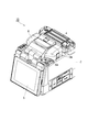
- FIG. 2 is a perspective view showing the appearance of the fusion splicer, showing the appearance of the windshield cover in a closed state.
- FIG. 3 is a perspective view showing the appearance of the fusion splicer, showing the appearance of the fusion splicer in a state where the windshield cover is opened and the internal structure of the fusion splicer can be seen.
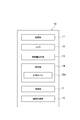
- FIG. 4 is a block diagram showing a functional configuration of the fusion splicer.
- FIG. 5 is a block diagram showing a hardware configuration of the fusion splicer.
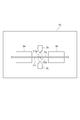
- FIG. 6 is a diagram showing the operation of the connection portion.
- FIG. 1 is a diagram schematically showing a configuration of an optical fiber fusion splicer system according to an embodiment of the present disclosure.
- FIG. 2 is a perspective view showing the appearance of the fusion splicer, showing the appearance of the
- FIG. 7 is a diagram showing the operation of the connection portion.
- FIG. 8 is a diagram showing the operation of the connection portion.
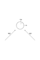
- FIG. 9 is a front view of the end face of one of the optical fibers.
- FIG. 10 is a diagram schematically showing the imaging data obtained in the imaging unit.
- FIG. 11 is a block diagram showing a functional configuration of the model creation device.
- FIG. 12 is a block diagram showing a hardware configuration of the model creation device.
- FIG. 13 is a flowchart showing the method according to the embodiment.
- optical fibers there are various types of optical fibers.
- the types of optical fibers include, for example, single mode fiber (SMF), multi mode fiber (MMF), general-purpose single mode fiber, distributed shift single mode fiber (DSF), and Features related to applications and optical characteristics such as non-zero dispersion shift single-mode fiber (NZDSF: Non-Zero DSF), and structure such as optical fiber diameter, core diameter, core and clad material, and radial refractive index distribution. It is distinguished by its characteristic characteristics.
- the optimum fusion conditions discharge time, relative position between optical fibers, etc.
- the pair of optical fibers are fused and connected vary depending on the combination of types of the pair of optical fibers.
- the type of optical fiber already laid is often unknown. Therefore, it is important for the fusion splicer to accurately discriminate the combination of the types of the pair of optical fibers to be connected.
- a discrimination model capable of discriminating the type of the optical fiber from the luminance distribution data in the radial direction of the optical fiber is created by using machine learning.
- machine learning since there are mechanical and structural variations in the imaging device provided in the fusion splicer, even if the same optical fiber is imaged, the obtained imaging data is small for each fusion splicer. Different to. Therefore, even if machine learning is performed based on the imaging data obtained from a plurality of fusion splicers, the accuracy of discrimination is limited.
- an object of the present disclosure is to provide a fusion splicing system for an optical fiber, a fusion splicer, and a method for fusion splicing an optical fiber, which can improve the discriminating accuracy of an optical fiber type.
- the type of the pair of optical fibers is input to the discrimination model by inputting the feature amount obtained from the imaging data provided by the imaging unit into the discrimination model, and the discrimination unit that discriminates the type of each pair of optical fibers and the discrimination result in the discrimination unit. It is provided with a plurality of fusion splicers having a connecting portion for fusion-bonding a pair of optical fibers to each other under the connection conditions according to the combination of the above.
- the model creation device classifies a plurality of fusion splicers into two or more groups, collects sample data for each group, and creates a discrimination model.
- the discriminating unit of each fusion splicer discriminates the type of each pair of optical fibers by using the discrimination model corresponding to the group to which each fusion splicer belongs.
- the fusion splicer is based on an imaging unit that images a pair of optical fibers to generate imaging data and the type of optical fiber to be connected based on the imaging data of the optical fiber to be connected.
- a discrimination model for discrimination which is a discrimination model created by machine learning using sample data showing the correspondence between the feature amount obtained from the imaged data of the optical fiber and the type of the optical fiber obtained from the feature amount.
- a discriminating unit that discriminates the types of each pair of optical fibers by inputting the feature amount obtained from the imaging data provided by the imaging unit, and a combination of the types of the pair of optical fibers based on the discriminating result in the discriminating unit.
- the discrimination model is created by classifying a plurality of fusion splicers into two or more groups and collecting sample data for each group.
- the discriminating unit discriminates the types of each pair of optical fibers using a discriminant model corresponding to the group to which the fusion splicer belongs.
- the method for fusion-bonding the optical fibers is to perform machine learning using sample data showing the correspondence between the feature amount obtained from the imaged data of the optical fiber and the type of the optical fiber, and try to connect the optical fibers.
- the type of the pair of optical fibers is based on the process of inputting the feature amount obtained from the imaging data generated in the process of generation into the discrimination model and discriminating the type of each pair of optical fibers and the discrimination result in the discriminating step.
- two or more fusion splicers that perform the step of generating imaging data, the step of discriminating, and the step of fusion splicing are presumed to have similar tendencies of imaging data.
- Classify into groups of collect sample data from multiple fusion splicers, and create a discrimination model for each group.
- the discriminating step the type of each pair of optical fibers is discriminated by using a discriminant model corresponding to the group to which the fusion splicer that performs the discriminating step belongs.
- fusion splicing system fusion splicer, and fusion splicing method
- sample data showing the correspondence between the feature amount obtained from the image pickup data of the optical fiber and the type of the optical fiber obtained from the feature amount is used.
- Machine learning is performed using this, and the type of optical fiber is discriminated using the obtained discriminant model. Therefore, high-precision discrimination based on machine learning is possible.
- a plurality of fusion splicers are classified into two or more groups in which the tendency of the imaging data is presumed to be similar, and sample data is collected for each group to create a discrimination model. Then, the type of each pair of optical fibers is discriminated by using the discriminant model corresponding to the group to which the own machine belongs.
- machine learning can be performed only within a group in which there is little mechanical and structural variation in the imaging unit, so that the accuracy of discriminating the optical fiber type based on machine learning can be further improved.
- machine learning may be deep learning. In this case, the accuracy of discriminating the type of optical fiber can be further improved.
- two or more groups shall be at least one of the inspection conditions of each fusion splicer and the inspection result of each fusion splicer. It may be classified based on the similarity. The similarity between the test conditions and the test results is considered to affect the similarity of the tendency of the imaging data. Therefore, in this case, the plurality of fusion splicers can be appropriately classified into two or more groups in which the tendency of the imaging data is presumed to be similar.
- two or more groups are obtained by imaging an optical fiber as a reference when inspecting each fusion splicer by an imaging unit. It may be classified based on the similarity of the captured data.
- the similarity of the imaging data obtained by imaging the reference optical fiber at the time of inspection represents the similarity of the tendency of the imaging data. Therefore, in this case, the plurality of fusion splicers can be appropriately classified into two or more groups in which the tendency of the imaging data is presumed to be similar.
- two or more groups have an environment in which an optical fiber, which is a reference when inspecting each fusion splicer, is imaged by an imaging unit. It may be classified based on the similarity of conditions. It is considered that the similarity of the environmental conditions when imaging the reference optical fiber at the time of inspection affects the similarity of the tendency of the imaging data. Therefore, in this case, the plurality of fusion splicers can be appropriately classified into two or more groups in which the tendency of the imaging data is presumed to be similar.
- two or more groups are classified based on the similarity of at least one of the manufacturer and date and time of manufacture of each fusion splicer. May be good.
- the similarity of at least one of the manufacturer of the fusion splicer and the date and time of manufacture is considered to affect the similarity of the tendency of the imaging data. Therefore, in this case, the plurality of fusion splicers can be appropriately classified into two or more groups in which the tendency of the imaging data is presumed to be similar.
- the two or more groups are based on the similarity of at least one of the manufacturer and date and time of the imaging unit of each fusion splicer. It may be classified. It is considered that the similarity of at least one of the manufacturer of the imaging unit and the manufacturing date and time affects the similarity of the tendency of the imaging data. Therefore, in this case, the plurality of fusion splicers can be appropriately classified into two or more groups in which the tendency of the imaging data is presumed to be similar.
- two or more groups may be classified based on the similarity of environmental conditions at the place of use of each fusion splicer.
- the similarity of environmental conditions at the place of use of the fusion splicer is considered to affect the similarity of the tendency of the imaging data. Therefore, in this case, the plurality of fusion splicers can be appropriately classified into two or more groups in which the tendency of the imaging data is presumed to be similar.
- two or more groups may be classified based on the similarity of the deterioration state of each fusion splicing machine.
- the similarity of the deterioration state of the fusion splicer is considered to affect the similarity of the tendency of the imaging data. Therefore, in this case, the plurality of fusion splicers can be appropriately classified into two or more groups in which the tendency of the imaging data is presumed to be similar.
- two or more groups may be classified based on the similarity of the optical fiber types to be connected in each fusion splicer. good.
- the similarity of the types of optical fibers to be connected is considered to affect the similarity of the tendency of the imaging data. Therefore, in this case, the plurality of fusion splicers can be appropriately classified into two or more groups in which the tendency of the imaging data is presumed to be similar.
- FIG. 1 is a diagram schematically showing a configuration of a fusion splicer connection system 1A according to an embodiment of the present disclosure.
- the fusion splicer system 1A includes a plurality of fusion splicer 10s and a model creation device 20.
- the fusion splicer 10 is a device for fusion splicing optical fibers.
- the model creation device 20 is a device that creates a discrimination model for discriminating the type of optical fiber.
- the model creation device 20 is a computer capable of communicating with a plurality of fusion splicers 10 via the information communication network 30.
- the information communication network 30 is, for example, the Internet.
- the location area of the model creation device 20 and the location area of the fusion splicer 10 are separated from each other.
- FIGS. 2 and 3 are perspective views showing the appearance of the fusion splicer 10.
- FIG. 2 shows an appearance in a state where the windshield cover is closed
- FIG. 3 shows an appearance in a state where the windshield cover is opened and the internal structure of the fusion splicer 10 can be seen.
- the fusion splicer 10 includes a box-shaped housing 2.
- a connecting portion 3 for fusion-bonding the optical fibers and a heater 4 are provided on the upper portion of the housing 2.
- the heater 4 is a portion that heats and shrinks the fiber reinforcing sleeve that covers the connecting portion between the optical fibers that are fused and connected at the connecting portion 3.
- the fusion splicer 10 includes a monitor 5 that displays a fusion connection status between optical fibers imaged by an imaging unit (described later) arranged inside the housing 2. Further, the fusion splicer 10 is provided with a windshield cover 6 for preventing wind from entering the connecting portion 3.
- the connection portion 3 has a holder mounting portion on which a pair of optical fiber holders 3a can be mounted, a pair of fiber positioning portions 3b, and a pair of discharge electrodes 3c.
- Each of the optical fibers to be fused is held and fixed to the optical fiber holder 3a, and each of the optical fiber holders 3a is placed and fixed to the holder mounting portion.
- the fiber positioning portion 3b is arranged between the pair of optical fiber holders 3a, and positions the tip end portion of the optical fiber held in each of the optical fiber holders 3a.
- the discharge electrode 3c is an electrode for fusing the tips of optical fibers to each other by arc discharge, and is arranged between a pair of fiber positioning portions 3b.
- the windshield cover 6 is connected to the housing 2 so as to cover the connecting portion 3 so as to be openable and closable.
- Each of the side surfaces 6a of the windshield cover 6 is formed with an introduction port 6b for introducing an optical fiber into the connection portion 3 (that is, into each of the optical fiber holders 3a).
- FIG. 4 is a block diagram showing a functional configuration of the fusion splicer 10.
- FIG. 5 is a block diagram showing a hardware configuration of the fusion splicer 10.
- the fusion splicer 10 has a connection unit 3, a communication unit 11, an imaging unit (camera) 12, a feature amount extraction unit 13, a discrimination unit 14, and a fusion control unit 15.
- the fusion splicer 10 is configured to include a computer having hardware such as a CPU 10a, a RAM 10b, a ROM 10c, an input device 10d, an auxiliary storage device 10e, and an output device 10f as its control unit. Will be done.
- Each function of the fusion splicer 10 is realized by operating these components by a program or the like. Further, these elements in the control unit are electrically connected to the connection unit 3, the monitor 5, the wireless communication module as the communication unit 11, and the image pickup unit 12 described above.
- the input device 10d may include a touch panel provided integrally with the monitor 5.
- the communication unit 11 is composed of, for example, a wireless LAN module, and transmits and receives various data to and from the model creation device 20 via an information communication network 30 such as the Internet.
- the imaging unit 12 captures images of the optical fibers to be connected from the radial direction of the optical fibers in a state of facing each other, and generates imaging data.
- the feature amount extraction unit 13 extracts two or more feature amounts for specifying the type of optical fiber from the image pickup data obtained from the image pickup unit 12.
- the feature amounts are, for example, the luminance distribution in the radial direction of the optical fiber, the outer diameter of the optical fiber, the outer diameter of the core, the ratio of the outer diameter of the core to the outer diameter of the optical fiber, the ratio of the area between the core and the clad of the optical fiber, and the light.
- the discrimination unit 14 stores and holds a discrimination model Md for discriminating the type of optical fiber.
- the discrimination unit 14 inputs the feature amount obtained from the feature amount extraction unit 13 into the discrimination model Md, and discriminates the types of each of the pair of optical fibers.
- the determination result by the determination unit 14 is displayed on the monitor 5.
- the user inputs the correct type via the input device 10d and corrects the determination result.
- the user may input each type of the pair of optical fibers via the input device 10d regardless of the discrimination result by the discrimination unit 14. In that case, the input by the user is preferentially adopted, and the type of each optical fiber is specified.
- the input may be replaced with the input of the corresponding type of optical fiber itself.
- the fusion control unit 15 controls the operation of the connection unit 3. That is, the fusion control unit 15 controls the contact operation between the tips of the optical fibers and the arc discharge at the connection unit 3 in response to the operation of the switch by the user.
- the contact operation between the tips of the optical fibers includes the positioning process of the optical fibers by the fiber positioning unit 3b, that is, the control of the tip position of each optical fiber.
- the control of the arc discharge includes the control of the discharge power, the discharge start timing and the discharge end timing.
- Various connection conditions such as the tip position of the optical fiber and the discharge power are preset for each combination of the types of the pair of optical fibers, and are stored in, for example, the ROM 10c.
- the fusion control unit 15 selects the connection conditions according to the combination of the types of the pair of optical fibers determined by the determination unit 14 or input by the user. Therefore, the connection unit 3 fuses and connects the pair of optical fibers to each other under the connection conditions according to the combination of the types of the pair of optical fibers based on the discrimination result in the discrimination unit 14 or the input result by the user. ..
- connection unit 3 The operation of the connection unit 3 is as follows. First, as shown in FIG. 6, the user holds the pair of optical fibers F1 and F2 to be connected in the optical fiber holder 3a, respectively. At this time, the end face F1a of the optical fiber F1 and the end face F2a of the optical fiber F2 are arranged so as to face each other. Next, the user instructs the fusion splicer 10 to start the fusion splicing. This instruction is given, for example, via a switch input. In response to this instruction, as shown in FIG. 7, the fusion control unit 15 positions the optical fibers F1 and F2 based on the positions of the end faces F1a and F2a set as the connection conditions. After that, as shown in FIG. 8, the fusion control unit 15 starts arc discharge between the pair of discharge electrodes 3c.
- the end faces F1a and F2a are separated from each other, and the arc discharge corresponds to a preliminary discharge for softening the end faces F1a and F2a in advance before fusion.
- the fusion control unit 15 controls the position of the fiber positioning unit 3b to bring the end faces F1a and F2a closer to each other and bring them into contact with each other. Then, by continuing the arc discharge (main discharge), the end faces F1a and F2a are further softened and fused to each other.
- connection conditions include the positions of the end faces F1a and F2a before the start of discharge, the distance between the end faces F1a and F2a before the start of discharge, the preliminary discharge time, the main discharge time, and the end faces F1a and F2a. It includes at least one of a pushing amount after contact, a pulling back amount after pushing each of the end faces F1a and F2a, a preliminary discharge power, a main discharge power, and a discharge power at the time of pulling back.
- the positions of the end faces F1a and F2a before the start of discharge are each based on the state shown in FIG. 6, that is, the line connecting the central axes of the pair of discharge electrodes (discharge central axis) at the start of pre-discharge. Refers to the positions of the end faces F1a and F2a. Depending on the position of these end faces, the amount of heating (melting amount) increases or decreases by changing the distance between the discharge center and each end face F1a, F2a, and the time required for movement until the end faces F1a, F2a come into contact with each other changes. do.
- the distance between the end faces F1a and F2a before the start of discharge means the state shown in FIG.
- the pre-discharge time is the time from the start of arc discharge in the state shown in FIG. 6 to the start of relative movement of the optical fibers F1 and F2 in order to bring the end faces F1a and F2a into contact with each other.
- the present discharge time refers to the time from when the end faces F1a and F2a come into contact with each other until the end of the arc discharge (in other words, the application of the voltage to the pair of discharge electrodes 3c is stopped).
- the preliminary discharge and the main discharge are performed continuously in time.
- the amount of pushing after the end faces F1a and F2a are in contact with each other is the amount of pushing in after the optical fibers F1 and F2 are relatively moved from the state shown in FIG. 6 to bring the end faces F1a and F2a into contact with each other and then discharged.
- the amount of pullback after pushing the end faces F1a and F2a together is the amount of pulling back after the end faces F1a and F2a are brought into contact with each other, and then the end faces F1a and F2a are pushed further. It refers to the moving distance when the optical fibers F1 and F2 are relatively moved in the direction in which they are separated from each other.
- the preliminary discharge power is the period from the start of arc discharge in the state shown in FIG. 6 to the start of relative movement of the optical fibers F1 and F2 in order to bring the end faces F1a and F2a into contact with each other. Arc discharge power.
- FIG. 9 is a view of the end surface F2a of one of the optical fibers F2 as viewed from the front (in the direction of the optical axis).
- the arrows MSX and MSY in the figure indicate the imaging direction by the imaging unit 12, respectively. That is, in this example, at least two imaging units 12 are installed, and the two imaging units 12 image the end faces F1a and F2a from directions orthogonal to each other in the radial direction of the optical fibers F1 and F2.
- a light source for illuminating the optical fibers F1 and F2 is arranged at a position facing the imaging unit 12 with the optical fibers F1 and F2 interposed therebetween.
- the light source is, for example, a light emitting diode.
- FIG. 10 is a diagram schematically showing each of the imaging data PX and PY obtained by the imaging unit 12 that images images from the directions MSX and MSY.
- the positions and shapes of the optical fibers F1 and F2 are confirmed by the contours of the core CR and the clad CL.
- the core CR is brightened by the illumination light from the light source
- the clad CL is darkened by the refraction of the illumination light from the light source.
- FIG. 11 is a block diagram showing a functional configuration of the model creation device 20.
- FIG. 12 is a block diagram showing a hardware configuration of the model creation device 20.
- the model creation device 20 functionally includes a communication unit 21 and a discrimination model creation unit 22.
- the model creation device 20 is configured to include a computer including hardware such as a CPU 20a, a RAM 20b, a ROM 20c, an input device 20d, a communication module 20e, an auxiliary storage device 20f, and an output device 20g. NS.
- Each function of the model creation device 20 is realized by operating these components by a program or the like.
- the communication unit 21 shown in FIG. 11 is a portion that communicates with a plurality of fusion splicers 10 via an information communication network 30 (see FIG. 1) such as the Internet.
- the communication unit 21 receives information on the feature quantities extracted from the imaging data PX and PY and the types of the optical fibers F1 and F2 from the plurality of fusion splicers 10 via the information communication network 30.
- the communication unit 21 may receive the image pickup data PX, PY itself instead of the feature amount extracted from the image pickup data PX, PY. In that case, the model creation device 20 obtains the feature amount from the image pickup data PX, PY. Extract. Further, the information regarding the types of the optical fibers F1 and F2 may be only the information input by the user.
- the communication unit 21 receives information regarding the types of optical fibers F1 and F2 input by the user (by selecting one of the manufacturing conditions preset for each type of optical fiber, the corresponding type of optical fiber is used. (Including the case where the input is replaced with the input of the optical fiber itself) and the feature amount (or the imaging data itself) extracted from the imaging data PX and PY of the optical fibers F1 and F2 are received from each fusion splicer 10.
- the communication unit 21 uses these received information as sample data Da showing the correspondence between the feature quantities obtained from the imaged data PX and PY of the optical fibers F1 and F2 and the types of the optical fibers F1 and F2. It is provided to the preparation unit 22.
- the discrimination model creation unit 22 performs machine learning using the sample data Da provided by the communication unit 21 and creates a discrimination model Md for discriminating the types of the optical fibers F1 and F2 based on the imaging data PX and PY. do.
- Machine learning is preferably deep learning.
- various techniques included in so-called supervised learning such as a neural network and a support vector machine can be applied.
- the discrimination model creation unit 22 continuously performs machine learning using a huge amount of sample data Da obtained from a large number of fusion splicers 10 in operation to improve the accuracy of the discrimination model Md.
- the discrimination model creation unit 22 of the present embodiment classifies the plurality of fusion splicers 10 into two or more groups presumed to have similar tendencies of the imaging data PX and PY. Then, the discrimination model creation unit 22 collects sample data Da for each group and creates a discrimination model Md for each group. Creating a discrimination model Md for each group means that machine learning is performed using only sample data Da obtained from a plurality of fusion splicers 10 belonging to a certain group, and the created discrimination model Md belongs to the group. It means that it is provided only to the fusion splicer 10.
- Two or more groups presumed to have similar tendencies in the imaging data PX and PY are classified based on, for example, at least one of the following items (1) to (7).
- Similarity of inspection results of the fusion splicer 10 When the inspection results of the fusion splicer 10 and particularly the inspection results of the inspection items related to the imaging unit 12 are similar to each other in the plurality of fusion splicers 10, they are used. It is presumed that the tendencies of the imaging data PX and PY are similar in the fusion splicer 10. For example, the optical fiber that serves as a reference when inspecting each fusion splicer 10 is imaged by the imaging unit 12, and the brightness distribution and the like in the obtained imaging data PX and PY are similar to each other in the plurality of fusion splicers 10. For example, if you are doing so.
- Similarity of environmental conditions at the place where the fusion splicer 10 is used A plurality of environmental conditions (for example, at least one of temperature (air temperature), humidity, and atmospheric pressure) at the place where the fusion splicer 10 is used are fused.
- the fusion splicers 10 are similar to each other, it is presumed that the tendencies of the imaging data PX and PY are similar in those fusion splicers 10. Therefore, for example, a plurality of fusion splicers 10 used in a hot and humid area are grouped into one group, and a plurality of fusion splicers 10 used in a cold region are grouped into another group, and the highlands are combined. It is conceivable to classify the plurality of fusion splicers 10 used in the above into a further group.
- the deteriorated state of the fusion splicer 10 is, for example, the elapsed time from the manufacturing date, the usage time, the number of discharges, the connection frequency, the degree of dirt on the discharge electrode 3c, and the light source that illuminates the optical fiber from the opposite side of the imaging unit 12. It is at least one of the dimming state, the degree of dirt on the lens, and the device diagnosis result.
- optical fibers F1 and F2 which are mainly targeted to be connected in the field where the fusion splicer 10 is used, are similar to each other in the plurality of fusion splicers 10. If so, it is presumed that the tendencies of the imaging data PX and PY are similar in those fusion splicers 10.
- the types of optical fibers F1 and F2 referred to here refer to rough types of optical fibers such as single-mode fiber and multimode fiber, general-purpose fiber and distributed shift fiber, and the like.
- the discrimination model Md created by collecting the sample data Da for each group is transmitted to the fusion splicer 10 belonging to each corresponding group via the communication unit 21.
- the discrimination unit 14 of each fusion splicer 10 discriminates the types of each of the pair of optical fibers F1 and F2 by using the discrimination model Md corresponding to the group to which the fusion splicer 10 belongs.
- FIG. 13 is a flowchart showing a method of fusion-bonding optical fibers according to the present embodiment. This method can be suitably realized by using the fusion splicing system 1A described above.
- the model creation step ST1 the optical fibers F1 and F2 to be connected by performing machine learning using the sample data Da showing the correspondence between the feature amount obtained from the imaging data of the optical fiber and the type of the optical fiber.
- a discrimination model Md for discriminating the types of the above based on the imaging data PX and PY of the optical fibers F1 and F2 is created.
- a plurality of fusion splicers 10 are classified into two or more groups presumed to have similar tendencies of imaging data PX and PY, and sample data Da is collected for each group.
- the imaging step ST2 a pair of optical fibers F1 and F2 are imaged to generate imaging data PX and PY.
- the discrimination step ST3 the feature amounts obtained from the image pickup data PX and PY generated in the imaging step ST2 are input to the discrimination model Md, and the types of the pair of optical fibers F1 and F2 are discriminated.
- the types of each of the pair of optical fibers F1 and F2 are discriminated by using the discrimination model Md corresponding to the group to which the fusion splicer 10 performing the discrimination step ST3 belongs.
- the connection step ST4 the pair of optical fibers F1 and F2 are fused and connected to each other under the connection conditions according to the combination of the types of the pair of optical fibers F1 and F2 based on the discrimination result in the discrimination step ST3. ..
- the fusion splicing system 1A, the fusion splicer 10, and the fusion splicing method of the present embodiment described above will be described.
- machine learning is performed using the sample data Da showing the correspondence between the feature amount obtained from the imaging data PX and PY of the optical fibers F1 and F2 and the types of the optical fibers F1 and F2, and the obtained discrimination is performed.
- the types of optical fibers F1 and F2 are discriminated using the model Md. Therefore, high-precision discrimination based on machine learning is possible.
- the plurality of fusion splicers 10 are classified into two or more groups presumed to have similar tendencies of the imaging data PX and PY, and sample data Da is collected for each group to create a discrimination model Md. .. Then, the types of each of the pair of optical fibers F1 and F2 are discriminated by using the discriminant model Md corresponding to the group to which the own machine belongs. As a result, machine learning can be performed only within the group in which the mechanical and structural variations of the imaging unit 12 are small, so that the accuracy of discriminating the optical fiber type based on the machine learning can be further improved.
- machine learning may be deep learning.
- the accuracy of discriminating the type of optical fiber can be further improved.
- the two or more groups may be classified based on the similarity of at least one of the inspection conditions and results of each fusion splicer 10.
- the similarity of the examination conditions and results is considered to affect the similarity of the tendency of the imaging data PX and PY. Therefore, in this case, the plurality of fusion splicers 10 can be appropriately classified into two or more groups presumed to have similar tendencies of the imaging data PX and PY.
- the above two or more groups are based on the similarity of the imaging data PX and PY obtained by imaging the optical fiber as a reference when inspecting each fusion splicer 10 by the imaging unit 12. It may be classified.
- the similarity of the imaging data PX and PY obtained by imaging the reference optical fiber at the time of inspection represents the similarity of the tendency of the imaging data PX and PY. Therefore, in this case, the plurality of fusion splicers 10 can be appropriately classified into two or more groups presumed to have similar tendencies of the imaging data PX and PY.
- the above two or more groups have similarities in environmental conditions (temperature, humidity, atmospheric pressure, etc.) when the optical fiber, which is a reference when inspecting each fusion splicer 10, is imaged by the imaging unit 12. It may be classified based on. It is considered that the similarity of the environmental conditions when the reference optical fiber is imaged at the time of inspection affects the similarity of the tendency of the imaging data PX and PY. Therefore, in this case, the plurality of fusion splicers 10 can be appropriately classified into two or more groups presumed to have similar tendencies of the imaging data PX and PY.
- the two or more groups may be classified based on the similarity of at least one of the manufacturer and the date and time of manufacture of each fusion splicer 10. It is considered that the similarity of at least one of the manufacturer and the date and time of manufacture of the fusion splicer 10 affects the similarity of the tendency of the imaging data PX and PY. Therefore, in this case, the plurality of fusion splicers 10 can be appropriately classified into two or more groups presumed to have similar tendencies of the imaging data PX and PY.
- the two or more groups may be classified based on the similarity of at least one of the manufacturer of the imaging unit 12 and the date and time of manufacture. It is considered that the similarity of at least one of the manufacturer and the date and time of manufacture of the imaging unit 12 affects the similarity of the tendency of the imaging data PX and PY. Therefore, in this case, the plurality of fusion splicers 10 can be appropriately classified into two or more groups presumed to have similar tendencies of the imaging data PX and PY.
- the above two or more groups may be classified based on the similarity of environmental conditions (temperature, humidity, atmospheric pressure, etc.) at the place of use of each fusion splicer 10. It is considered that the similarity of the environmental conditions at the place where the fusion splicer 10 is used affects the similarity of the tendency of the imaging data PX and PY. Therefore, in this case, the plurality of fusion splicers 10 can be appropriately classified into two or more groups presumed to have similar tendencies of the imaging data PX and PY.
- the above two or more groups may be classified based on the similarity of the deterioration states of each fusion splicer 10. It is considered that the similarity of the deteriorated state of the fusion splicer 10 affects the similarity of the tendency of the imaging data PX and PY. Therefore, in this case, the plurality of fusion splicers 10 can be appropriately classified into two or more groups presumed to have similar tendencies of the imaging data PX and PY.
- the above two or more groups may be classified based on the similarity of the types of optical fibers to be connected in each fusion splicer 10.
- the similarity of the types of optical fibers to be connected is considered to affect the similarity of the tendency of the imaging data PX and PY. Therefore, in this case, the plurality of fusion splicers 10 can be appropriately classified into two or more groups presumed to have similar tendencies of the imaging data PX and PY.
- the fusion splicing system for the optical fiber, the fusion splicer, and the method for fusion splicing the optical fiber according to the present disclosure are not limited to the above-described embodiment, and various other modifications are possible.
- the method of classifying two or more groups in which the tendency of the imaging data is presumed to be similar is not limited to that exemplified in the above embodiment.
- Output device 21 ... Communication unit 22 . Discrimination model creation unit 30 ... Information communication network CL ... Clad CR ... Core Da ... Sample data F1, F2 ... Optical fiber F1a, F2a ... End face Md ... Discrimination model MSX, MSY ... Direction PX, PY ... Imaging data ST1 ... Model creation process ST2 ... Imaging process ST3 ... Discrimination process ST4 ... Connection process
Landscapes
- Physics & Mathematics (AREA)
- Engineering & Computer Science (AREA)
- Plasma & Fusion (AREA)
- General Physics & Mathematics (AREA)
- Optics & Photonics (AREA)
- Mechanical Coupling Of Light Guides (AREA)
Priority Applications (7)
| Application Number | Priority Date | Filing Date | Title |
|---|---|---|---|
| PCT/JP2020/016860 WO2021210162A1 (ja) | 2020-04-17 | 2020-04-17 | 光ファイバのための融着接続システム、融着接続機、及び光ファイバを融着接続する方法 |
| JP2022515378A JP7646973B2 (ja) | 2020-04-17 | 2021-04-12 | 光ファイバのための融着接続システム、融着接続機、モデル作成装置、及び光ファイバを融着接続する方法 |
| PCT/JP2021/015210 WO2021210546A1 (ja) | 2020-04-17 | 2021-04-12 | 光ファイバのための融着接続システム、融着接続機、モデル作成装置、及び光ファイバを融着接続する方法 |
| CN202180027320.4A CN115362399A (zh) | 2020-04-17 | 2021-04-12 | 用于光纤的熔接系统、熔接机、模型制作装置以及熔接光纤的方法 |
| KR1020227039189A KR20230003501A (ko) | 2020-04-17 | 2021-04-12 | 광파이버를 위한 융착 접속 시스템, 융착 접속기, 모델 작성 장치, 및 광파이버를 융착 접속하는 방법 |
| US17/907,686 US12607805B2 (en) | 2020-04-17 | 2021-04-12 | Fusion splicing system for optical fibers, fusion splicer, model creation device, and method for fusion splicing optical fibers |
| EP21788759.5A EP4137851A4 (en) | 2020-04-17 | 2021-04-12 | Fusion splicing system for optical fibers, fusion splicer, model creation device, and method for fusion splicing optical fibers |
Applications Claiming Priority (1)
| Application Number | Priority Date | Filing Date | Title |
|---|---|---|---|
| PCT/JP2020/016860 WO2021210162A1 (ja) | 2020-04-17 | 2020-04-17 | 光ファイバのための融着接続システム、融着接続機、及び光ファイバを融着接続する方法 |
Publications (1)
| Publication Number | Publication Date |
|---|---|
| WO2021210162A1 true WO2021210162A1 (ja) | 2021-10-21 |
Family
ID=78084817
Family Applications (2)
| Application Number | Title | Priority Date | Filing Date |
|---|---|---|---|
| PCT/JP2020/016860 Ceased WO2021210162A1 (ja) | 2020-04-17 | 2020-04-17 | 光ファイバのための融着接続システム、融着接続機、及び光ファイバを融着接続する方法 |
| PCT/JP2021/015210 Ceased WO2021210546A1 (ja) | 2020-04-17 | 2021-04-12 | 光ファイバのための融着接続システム、融着接続機、モデル作成装置、及び光ファイバを融着接続する方法 |
Family Applications After (1)
| Application Number | Title | Priority Date | Filing Date |
|---|---|---|---|
| PCT/JP2021/015210 Ceased WO2021210546A1 (ja) | 2020-04-17 | 2021-04-12 | 光ファイバのための融着接続システム、融着接続機、モデル作成装置、及び光ファイバを融着接続する方法 |
Country Status (6)
| Country | Link |
|---|---|
| US (1) | US12607805B2 (https=) |
| EP (1) | EP4137851A4 (https=) |
| JP (1) | JP7646973B2 (https=) |
| KR (1) | KR20230003501A (https=) |
| CN (1) | CN115362399A (https=) |
| WO (2) | WO2021210162A1 (https=) |
Families Citing this family (1)
| Publication number | Priority date | Publication date | Assignee | Title |
|---|---|---|---|---|
| KR102774396B1 (ko) | 2022-08-16 | 2025-02-27 | (주)파이버폭스 | 인공 지능을 활용한 광 선로 작업 검증 장치 및 방법 |
Citations (6)
| Publication number | Priority date | Publication date | Assignee | Title |
|---|---|---|---|---|
| CN102567745A (zh) * | 2011-12-29 | 2012-07-11 | 北京航天时代光电科技有限公司 | 一种光纤熔接质量的自动检测方法 |
| JP2015172736A (ja) * | 2014-02-19 | 2015-10-01 | ヤマハ株式会社 | 音声解析装置 |
| JP2016097228A (ja) * | 2014-11-26 | 2016-05-30 | 株式会社日立システムズ | 行動分類システム、行動分類装置及び行動分類方法 |
| JP2016152011A (ja) * | 2015-02-19 | 2016-08-22 | ファナック株式会社 | 制御装置の故障予測システム |
| JP2019118940A (ja) * | 2018-01-09 | 2019-07-22 | ファナック株式会社 | ファイバレーザ装置及び機械学習装置 |
| JP2020020997A (ja) * | 2018-08-02 | 2020-02-06 | 古河電気工業株式会社 | 融着接続システム、融着接続機及び光ファイバ種判別方法 |
Family Cites Families (3)
| Publication number | Priority date | Publication date | Assignee | Title |
|---|---|---|---|---|
| JP4367597B2 (ja) * | 2000-12-05 | 2009-11-18 | 住友電気工業株式会社 | 融着接続装置および融着接続方法 |
| WO2014205214A1 (en) * | 2013-06-19 | 2014-12-24 | Afl Telecommunications Llc | Auto mode selection in fiber optic end-face images |
| JP6943820B2 (ja) | 2018-08-02 | 2021-10-06 | 古河電気工業株式会社 | 融着接続システム、融着接続機及び光ファイバの回転角判定方法 |
-
2020
- 2020-04-17 WO PCT/JP2020/016860 patent/WO2021210162A1/ja not_active Ceased
-
2021
- 2021-04-12 US US17/907,686 patent/US12607805B2/en active Active
- 2021-04-12 WO PCT/JP2021/015210 patent/WO2021210546A1/ja not_active Ceased
- 2021-04-12 CN CN202180027320.4A patent/CN115362399A/zh active Pending
- 2021-04-12 JP JP2022515378A patent/JP7646973B2/ja active Active
- 2021-04-12 EP EP21788759.5A patent/EP4137851A4/en active Pending
- 2021-04-12 KR KR1020227039189A patent/KR20230003501A/ko active Pending
Patent Citations (6)
| Publication number | Priority date | Publication date | Assignee | Title |
|---|---|---|---|---|
| CN102567745A (zh) * | 2011-12-29 | 2012-07-11 | 北京航天时代光电科技有限公司 | 一种光纤熔接质量的自动检测方法 |
| JP2015172736A (ja) * | 2014-02-19 | 2015-10-01 | ヤマハ株式会社 | 音声解析装置 |
| JP2016097228A (ja) * | 2014-11-26 | 2016-05-30 | 株式会社日立システムズ | 行動分類システム、行動分類装置及び行動分類方法 |
| JP2016152011A (ja) * | 2015-02-19 | 2016-08-22 | ファナック株式会社 | 制御装置の故障予測システム |
| JP2019118940A (ja) * | 2018-01-09 | 2019-07-22 | ファナック株式会社 | ファイバレーザ装置及び機械学習装置 |
| JP2020020997A (ja) * | 2018-08-02 | 2020-02-06 | 古河電気工業株式会社 | 融着接続システム、融着接続機及び光ファイバ種判別方法 |
Also Published As
| Publication number | Publication date |
|---|---|
| EP4137851A1 (en) | 2023-02-22 |
| US12607805B2 (en) | 2026-04-21 |
| KR20230003501A (ko) | 2023-01-06 |
| JP7646973B2 (ja) | 2025-03-18 |
| US20230126843A1 (en) | 2023-04-27 |
| CN115362399A (zh) | 2022-11-18 |
| JPWO2021210546A1 (https=) | 2021-10-21 |
| EP4137851A4 (en) | 2023-09-20 |
| WO2021210546A1 (ja) | 2021-10-21 |
Similar Documents
| Publication | Publication Date | Title |
|---|---|---|
| US10921520B2 (en) | Fusion splicing system, fusion splicer and method of determining rotation angle of optical fiber | |
| US20200056960A1 (en) | Fusion splicing system, fusion splicer and method of determining type of optical fiber | |
| JP4367597B2 (ja) | 融着接続装置および融着接続方法 | |
| JP2012083635A (ja) | 光ファイバ融着接続方法 | |
| SE511966C2 (sv) | Förfarande och anordning för att hopskarva ändarna hos två optiska fibrer av olika typ med varandra | |
| JP7646973B2 (ja) | 光ファイバのための融着接続システム、融着接続機、モデル作成装置、及び光ファイバを融着接続する方法 | |
| JP7648039B2 (ja) | 融着接続機、融着接続システム、及び光ファイバを融着接続する方法 | |
| JP4856840B2 (ja) | 光ファイバの種類の決定 | |
| US7690850B2 (en) | Apparatus for splicing optical fibers | |
| JP2025114755A (ja) | 光ファイバの融着接続機及び光ファイバを融着接続する方法 | |
| WO2020179927A1 (ja) | 光ファイバの融着接続機、及び、光ファイバの融着接続方法 | |
| US11144603B2 (en) | Fusion condition providing system | |
| JP4032960B2 (ja) | 光ファイバ融着接続装置 | |
| JP7028615B2 (ja) | 融着条件提供システム | |
| Jackson | Mass fusion splicing of optical ribbon fiber: manufacturing process development | |
| JPH08160246A (ja) | ファイバ融着延伸型偏波ビームスプリッタ |
Legal Events
| Date | Code | Title | Description |
|---|---|---|---|
| 121 | Ep: the epo has been informed by wipo that ep was designated in this application |
Ref document number: 20931426 Country of ref document: EP Kind code of ref document: A1 |
|
| NENP | Non-entry into the national phase |
Ref country code: DE |
|
| 122 | Ep: pct application non-entry in european phase |
Ref document number: 20931426 Country of ref document: EP Kind code of ref document: A1 |
|
| NENP | Non-entry into the national phase |
Ref country code: JP |