WO2021210162A1 - 光ファイバのための融着接続システム、融着接続機、及び光ファイバを融着接続する方法 - Google Patents
光ファイバのための融着接続システム、融着接続機、及び光ファイバを融着接続する方法 Download PDFInfo
- Publication number
- WO2021210162A1 WO2021210162A1 PCT/JP2020/016860 JP2020016860W WO2021210162A1 WO 2021210162 A1 WO2021210162 A1 WO 2021210162A1 JP 2020016860 W JP2020016860 W JP 2020016860W WO 2021210162 A1 WO2021210162 A1 WO 2021210162A1
- Authority
- WO
- WIPO (PCT)
- Prior art keywords
- fusion
- optical fibers
- optical fiber
- pair
- imaging
- Prior art date
Links
Images


Classifications
-
- G—PHYSICS
- G02—OPTICS
- G02B—OPTICAL ELEMENTS, SYSTEMS OR APPARATUS
- G02B6/00—Light guides; Structural details of arrangements comprising light guides and other optical elements, e.g. couplings
- G02B6/24—Coupling light guides
- G02B6/255—Splicing of light guides, e.g. by fusion or bonding
- G02B6/2553—Splicing machines, e.g. optical fibre fusion splicer
-
- G—PHYSICS
- G02—OPTICS
- G02B—OPTICAL ELEMENTS, SYSTEMS OR APPARATUS
- G02B6/00—Light guides; Structural details of arrangements comprising light guides and other optical elements, e.g. couplings
- G02B6/24—Coupling light guides
- G02B6/255—Splicing of light guides, e.g. by fusion or bonding
- G02B6/2551—Splicing of light guides, e.g. by fusion or bonding using thermal methods, e.g. fusion welding by arc discharge, laser beam, plasma torch
Definitions
- the present disclosure relates to a fusion splicing system for an optical fiber, a fusion splicer, and a method for fusion splicing an optical fiber.
- Patent Document 1 and Patent Document 2 disclose techniques relating to a fusion splicer, a fusion splicer, and an optical fiber type discrimination method.
- the fusion splicing system of the present disclosure includes a model creation device and a plurality of fusion splicing machines.
- the model creation device performs machine learning using sample data showing the correspondence between the feature amount obtained from the imaged data of the optical fiber and the type of the optical fiber, and attempts to connect the type of the optical fiber to be connected.
- Each of the plurality of fusion splicers has an imaging unit, a discriminating unit, and a connecting unit.
- the imaging unit captures a pair of optical fibers to generate imaging data.
- the discriminating unit inputs the feature amount obtained from the imaging data provided by the imaging unit into the discriminating model, and discriminates the types of each pair of optical fibers.
- the connection unit fuses and connects the pair of optical fibers to each other under the connection conditions according to the combination of the types of the pair of optical fibers.
- the model creation device classifies a plurality of fusion splicers into two or more groups presumed to have similar tendencies of imaging data, collects sample data for each group, and creates a discrimination model.
- the discriminating unit of each fusion splicer discriminates the type of each pair of optical fibers by using the discrimination model corresponding to the group to which each fusion splicer belongs.
- the fusion splicer of the present disclosure includes an imaging unit, a discriminating unit, and a connecting unit.
- the imaging unit captures a pair of optical fibers to generate imaging data.
- the discrimination unit is a discrimination model for discriminating the type of the optical fiber to be connected based on the image pickup data of the optical fiber, and the feature amount obtained from the image pickup data of the optical fiber and the light obtained from the feature amount.
- the features obtained from the imaging data provided by the imaging unit are input to the discrimination model created by machine learning using sample data showing the correspondence with the fiber types, and the types of each pair of optical fibers are discriminated. do.
- the connection unit fuses and connects the pair of optical fibers to each other under the connection conditions according to the combination of the types of the pair of optical fibers.
- the discrimination model is created by classifying a plurality of fusion splicers into two or more groups in which the tendency of the imaging data is presumed to be similar, and collecting sample data for each group.
- the discriminating unit discriminates the types of each of the pair of optical fibers by using the discriminating model corresponding to the group to which the fusion splicer belongs.
- machine learning is performed using sample data showing the correspondence between the feature amount obtained from the imaged data of the optical fiber and the type of the optical fiber, and the optical fiber to be connected is to be connected.
- the connection according to the combination of the types of the pair of optical fibers It includes a step of fusing and connecting a pair of optical fibers to each other under certain conditions.
- two or more fusion splicers that perform the step of generating imaging data, the step of discriminating, and the step of fusion splicing are presumed to have similar tendencies of imaging data.
- Classify into groups of collect sample data from multiple fusion splicers, and create a discrimination model for each group.
- the type of each pair of optical fibers is discriminated by using a discriminant model corresponding to the group to which the fusion splicer that performs the discriminating step belongs.
- FIG. 1 is a diagram schematically showing a configuration of an optical fiber fusion splicer system according to an embodiment of the present disclosure.
- FIG. 2 is a perspective view showing the appearance of the fusion splicer, showing the appearance of the windshield cover in a closed state.
- FIG. 3 is a perspective view showing the appearance of the fusion splicer, showing the appearance of the fusion splicer in a state where the windshield cover is opened and the internal structure of the fusion splicer can be seen.
- FIG. 4 is a block diagram showing a functional configuration of the fusion splicer.
- FIG. 5 is a block diagram showing a hardware configuration of the fusion splicer.
- FIG. 6 is a diagram showing the operation of the connection portion.
- FIG. 1 is a diagram schematically showing a configuration of an optical fiber fusion splicer system according to an embodiment of the present disclosure.
- FIG. 2 is a perspective view showing the appearance of the fusion splicer, showing the appearance of the
- FIG. 7 is a diagram showing the operation of the connection portion.
- FIG. 8 is a diagram showing the operation of the connection portion.
- FIG. 9 is a front view of the end face of one of the optical fibers.
- FIG. 10 is a diagram schematically showing the imaging data obtained in the imaging unit.
- FIG. 11 is a block diagram showing a functional configuration of the model creation device.
- FIG. 12 is a block diagram showing a hardware configuration of the model creation device.
- FIG. 13 is a flowchart showing the method according to the embodiment.
- optical fibers there are various types of optical fibers.
- the types of optical fibers include, for example, single mode fiber (SMF), multi mode fiber (MMF), general-purpose single mode fiber, distributed shift single mode fiber (DSF), and Features related to applications and optical characteristics such as non-zero dispersion shift single-mode fiber (NZDSF: Non-Zero DSF), and structure such as optical fiber diameter, core diameter, core and clad material, and radial refractive index distribution. It is distinguished by its characteristic characteristics.
- the optimum fusion conditions discharge time, relative position between optical fibers, etc.
- the pair of optical fibers are fused and connected vary depending on the combination of types of the pair of optical fibers.
- the type of optical fiber already laid is often unknown. Therefore, it is important for the fusion splicer to accurately discriminate the combination of the types of the pair of optical fibers to be connected.
- a discrimination model capable of discriminating the type of the optical fiber from the luminance distribution data in the radial direction of the optical fiber is created by using machine learning.
- machine learning since there are mechanical and structural variations in the imaging device provided in the fusion splicer, even if the same optical fiber is imaged, the obtained imaging data is small for each fusion splicer. Different to. Therefore, even if machine learning is performed based on the imaging data obtained from a plurality of fusion splicers, the accuracy of discrimination is limited.
- an object of the present disclosure is to provide a fusion splicing system for an optical fiber, a fusion splicer, and a method for fusion splicing an optical fiber, which can improve the discriminating accuracy of an optical fiber type.
- the type of the pair of optical fibers is input to the discrimination model by inputting the feature amount obtained from the imaging data provided by the imaging unit into the discrimination model, and the discrimination unit that discriminates the type of each pair of optical fibers and the discrimination result in the discrimination unit. It is provided with a plurality of fusion splicers having a connecting portion for fusion-bonding a pair of optical fibers to each other under the connection conditions according to the combination of the above.
- the model creation device classifies a plurality of fusion splicers into two or more groups, collects sample data for each group, and creates a discrimination model.
- the discriminating unit of each fusion splicer discriminates the type of each pair of optical fibers by using the discrimination model corresponding to the group to which each fusion splicer belongs.
- the fusion splicer is based on an imaging unit that images a pair of optical fibers to generate imaging data and the type of optical fiber to be connected based on the imaging data of the optical fiber to be connected.
- a discrimination model for discrimination which is a discrimination model created by machine learning using sample data showing the correspondence between the feature amount obtained from the imaged data of the optical fiber and the type of the optical fiber obtained from the feature amount.
- a discriminating unit that discriminates the types of each pair of optical fibers by inputting the feature amount obtained from the imaging data provided by the imaging unit, and a combination of the types of the pair of optical fibers based on the discriminating result in the discriminating unit.
- the discrimination model is created by classifying a plurality of fusion splicers into two or more groups and collecting sample data for each group.
- the discriminating unit discriminates the types of each pair of optical fibers using a discriminant model corresponding to the group to which the fusion splicer belongs.
- the method for fusion-bonding the optical fibers is to perform machine learning using sample data showing the correspondence between the feature amount obtained from the imaged data of the optical fiber and the type of the optical fiber, and try to connect the optical fibers.
- the type of the pair of optical fibers is based on the process of inputting the feature amount obtained from the imaging data generated in the process of generation into the discrimination model and discriminating the type of each pair of optical fibers and the discrimination result in the discriminating step.
- two or more fusion splicers that perform the step of generating imaging data, the step of discriminating, and the step of fusion splicing are presumed to have similar tendencies of imaging data.
- Classify into groups of collect sample data from multiple fusion splicers, and create a discrimination model for each group.
- the discriminating step the type of each pair of optical fibers is discriminated by using a discriminant model corresponding to the group to which the fusion splicer that performs the discriminating step belongs.
- fusion splicing system fusion splicer, and fusion splicing method
- sample data showing the correspondence between the feature amount obtained from the image pickup data of the optical fiber and the type of the optical fiber obtained from the feature amount is used.
- Machine learning is performed using this, and the type of optical fiber is discriminated using the obtained discriminant model. Therefore, high-precision discrimination based on machine learning is possible.
- a plurality of fusion splicers are classified into two or more groups in which the tendency of the imaging data is presumed to be similar, and sample data is collected for each group to create a discrimination model. Then, the type of each pair of optical fibers is discriminated by using the discriminant model corresponding to the group to which the own machine belongs.
- machine learning can be performed only within a group in which there is little mechanical and structural variation in the imaging unit, so that the accuracy of discriminating the optical fiber type based on machine learning can be further improved.
- machine learning may be deep learning. In this case, the accuracy of discriminating the type of optical fiber can be further improved.
- two or more groups shall be at least one of the inspection conditions of each fusion splicer and the inspection result of each fusion splicer. It may be classified based on the similarity. The similarity between the test conditions and the test results is considered to affect the similarity of the tendency of the imaging data. Therefore, in this case, the plurality of fusion splicers can be appropriately classified into two or more groups in which the tendency of the imaging data is presumed to be similar.
- two or more groups are obtained by imaging an optical fiber as a reference when inspecting each fusion splicer by an imaging unit. It may be classified based on the similarity of the captured data.
- the similarity of the imaging data obtained by imaging the reference optical fiber at the time of inspection represents the similarity of the tendency of the imaging data. Therefore, in this case, the plurality of fusion splicers can be appropriately classified into two or more groups in which the tendency of the imaging data is presumed to be similar.
- two or more groups have an environment in which an optical fiber, which is a reference when inspecting each fusion splicer, is imaged by an imaging unit. It may be classified based on the similarity of conditions. It is considered that the similarity of the environmental conditions when imaging the reference optical fiber at the time of inspection affects the similarity of the tendency of the imaging data. Therefore, in this case, the plurality of fusion splicers can be appropriately classified into two or more groups in which the tendency of the imaging data is presumed to be similar.
- two or more groups are classified based on the similarity of at least one of the manufacturer and date and time of manufacture of each fusion splicer. May be good.
- the similarity of at least one of the manufacturer of the fusion splicer and the date and time of manufacture is considered to affect the similarity of the tendency of the imaging data. Therefore, in this case, the plurality of fusion splicers can be appropriately classified into two or more groups in which the tendency of the imaging data is presumed to be similar.
- the two or more groups are based on the similarity of at least one of the manufacturer and date and time of the imaging unit of each fusion splicer. It may be classified. It is considered that the similarity of at least one of the manufacturer of the imaging unit and the manufacturing date and time affects the similarity of the tendency of the imaging data. Therefore, in this case, the plurality of fusion splicers can be appropriately classified into two or more groups in which the tendency of the imaging data is presumed to be similar.
- two or more groups may be classified based on the similarity of environmental conditions at the place of use of each fusion splicer.
- the similarity of environmental conditions at the place of use of the fusion splicer is considered to affect the similarity of the tendency of the imaging data. Therefore, in this case, the plurality of fusion splicers can be appropriately classified into two or more groups in which the tendency of the imaging data is presumed to be similar.
- two or more groups may be classified based on the similarity of the deterioration state of each fusion splicing machine.
- the similarity of the deterioration state of the fusion splicer is considered to affect the similarity of the tendency of the imaging data. Therefore, in this case, the plurality of fusion splicers can be appropriately classified into two or more groups in which the tendency of the imaging data is presumed to be similar.
- two or more groups may be classified based on the similarity of the optical fiber types to be connected in each fusion splicer. good.
- the similarity of the types of optical fibers to be connected is considered to affect the similarity of the tendency of the imaging data. Therefore, in this case, the plurality of fusion splicers can be appropriately classified into two or more groups in which the tendency of the imaging data is presumed to be similar.
- FIG. 1 is a diagram schematically showing a configuration of a fusion splicer connection system 1A according to an embodiment of the present disclosure.
- the fusion splicer system 1A includes a plurality of fusion splicer 10s and a model creation device 20.
- the fusion splicer 10 is a device for fusion splicing optical fibers.
- the model creation device 20 is a device that creates a discrimination model for discriminating the type of optical fiber.
- the model creation device 20 is a computer capable of communicating with a plurality of fusion splicers 10 via the information communication network 30.
- the information communication network 30 is, for example, the Internet.
- the location area of the model creation device 20 and the location area of the fusion splicer 10 are separated from each other.
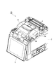
- FIGS. 2 and 3 are perspective views showing the appearance of the fusion splicer 10.
- FIG. 2 shows an appearance in a state where the windshield cover is closed
- FIG. 3 shows an appearance in a state where the windshield cover is opened and the internal structure of the fusion splicer 10 can be seen.
- the fusion splicer 10 includes a box-shaped housing 2.
- a connecting portion 3 for fusion-bonding the optical fibers and a heater 4 are provided on the upper portion of the housing 2.
- the heater 4 is a portion that heats and shrinks the fiber reinforcing sleeve that covers the connecting portion between the optical fibers that are fused and connected at the connecting portion 3.
- the fusion splicer 10 includes a monitor 5 that displays a fusion connection status between optical fibers imaged by an imaging unit (described later) arranged inside the housing 2. Further, the fusion splicer 10 is provided with a windshield cover 6 for preventing wind from entering the connecting portion 3.
- the connection portion 3 has a holder mounting portion on which a pair of optical fiber holders 3a can be mounted, a pair of fiber positioning portions 3b, and a pair of discharge electrodes 3c.
- Each of the optical fibers to be fused is held and fixed to the optical fiber holder 3a, and each of the optical fiber holders 3a is placed and fixed to the holder mounting portion.
- the fiber positioning portion 3b is arranged between the pair of optical fiber holders 3a, and positions the tip end portion of the optical fiber held in each of the optical fiber holders 3a.
- the discharge electrode 3c is an electrode for fusing the tips of optical fibers to each other by arc discharge, and is arranged between a pair of fiber positioning portions 3b.
- the windshield cover 6 is connected to the housing 2 so as to cover the connecting portion 3 so as to be openable and closable.
- Each of the side surfaces 6a of the windshield cover 6 is formed with an introduction port 6b for introducing an optical fiber into the connection portion 3 (that is, into each of the optical fiber holders 3a).
- FIG. 4 is a block diagram showing a functional configuration of the fusion splicer 10.
- FIG. 5 is a block diagram showing a hardware configuration of the fusion splicer 10.
- the fusion splicer 10 has a connection unit 3, a communication unit 11, an imaging unit (camera) 12, a feature amount extraction unit 13, a discrimination unit 14, and a fusion control unit 15.
- the fusion splicer 10 is configured to include a computer having hardware such as a CPU 10a, a RAM 10b, a ROM 10c, an input device 10d, an auxiliary storage device 10e, and an output device 10f as its control unit. Will be done.
- Each function of the fusion splicer 10 is realized by operating these components by a program or the like. Further, these elements in the control unit are electrically connected to the connection unit 3, the monitor 5, the wireless communication module as the communication unit 11, and the image pickup unit 12 described above.
- the input device 10d may include a touch panel provided integrally with the monitor 5.
- the communication unit 11 is composed of, for example, a wireless LAN module, and transmits and receives various data to and from the model creation device 20 via an information communication network 30 such as the Internet.
- the imaging unit 12 captures images of the optical fibers to be connected from the radial direction of the optical fibers in a state of facing each other, and generates imaging data.
- the feature amount extraction unit 13 extracts two or more feature amounts for specifying the type of optical fiber from the image pickup data obtained from the image pickup unit 12.
- the feature amounts are, for example, the luminance distribution in the radial direction of the optical fiber, the outer diameter of the optical fiber, the outer diameter of the core, the ratio of the outer diameter of the core to the outer diameter of the optical fiber, the ratio of the area between the core and the clad of the optical fiber, and the light.
- the discrimination unit 14 stores and holds a discrimination model Md for discriminating the type of optical fiber.
- the discrimination unit 14 inputs the feature amount obtained from the feature amount extraction unit 13 into the discrimination model Md, and discriminates the types of each of the pair of optical fibers.
- the determination result by the determination unit 14 is displayed on the monitor 5.
- the user inputs the correct type via the input device 10d and corrects the determination result.
- the user may input each type of the pair of optical fibers via the input device 10d regardless of the discrimination result by the discrimination unit 14. In that case, the input by the user is preferentially adopted, and the type of each optical fiber is specified.
- the input may be replaced with the input of the corresponding type of optical fiber itself.
- the fusion control unit 15 controls the operation of the connection unit 3. That is, the fusion control unit 15 controls the contact operation between the tips of the optical fibers and the arc discharge at the connection unit 3 in response to the operation of the switch by the user.
- the contact operation between the tips of the optical fibers includes the positioning process of the optical fibers by the fiber positioning unit 3b, that is, the control of the tip position of each optical fiber.
- the control of the arc discharge includes the control of the discharge power, the discharge start timing and the discharge end timing.
- Various connection conditions such as the tip position of the optical fiber and the discharge power are preset for each combination of the types of the pair of optical fibers, and are stored in, for example, the ROM 10c.
- the fusion control unit 15 selects the connection conditions according to the combination of the types of the pair of optical fibers determined by the determination unit 14 or input by the user. Therefore, the connection unit 3 fuses and connects the pair of optical fibers to each other under the connection conditions according to the combination of the types of the pair of optical fibers based on the discrimination result in the discrimination unit 14 or the input result by the user. ..
- connection unit 3 The operation of the connection unit 3 is as follows. First, as shown in FIG. 6, the user holds the pair of optical fibers F1 and F2 to be connected in the optical fiber holder 3a, respectively. At this time, the end face F1a of the optical fiber F1 and the end face F2a of the optical fiber F2 are arranged so as to face each other. Next, the user instructs the fusion splicer 10 to start the fusion splicing. This instruction is given, for example, via a switch input. In response to this instruction, as shown in FIG. 7, the fusion control unit 15 positions the optical fibers F1 and F2 based on the positions of the end faces F1a and F2a set as the connection conditions. After that, as shown in FIG. 8, the fusion control unit 15 starts arc discharge between the pair of discharge electrodes 3c.
- the end faces F1a and F2a are separated from each other, and the arc discharge corresponds to a preliminary discharge for softening the end faces F1a and F2a in advance before fusion.
- the fusion control unit 15 controls the position of the fiber positioning unit 3b to bring the end faces F1a and F2a closer to each other and bring them into contact with each other. Then, by continuing the arc discharge (main discharge), the end faces F1a and F2a are further softened and fused to each other.
- connection conditions include the positions of the end faces F1a and F2a before the start of discharge, the distance between the end faces F1a and F2a before the start of discharge, the preliminary discharge time, the main discharge time, and the end faces F1a and F2a. It includes at least one of a pushing amount after contact, a pulling back amount after pushing each of the end faces F1a and F2a, a preliminary discharge power, a main discharge power, and a discharge power at the time of pulling back.
- the positions of the end faces F1a and F2a before the start of discharge are each based on the state shown in FIG. 6, that is, the line connecting the central axes of the pair of discharge electrodes (discharge central axis) at the start of pre-discharge. Refers to the positions of the end faces F1a and F2a. Depending on the position of these end faces, the amount of heating (melting amount) increases or decreases by changing the distance between the discharge center and each end face F1a, F2a, and the time required for movement until the end faces F1a, F2a come into contact with each other changes. do.
- the distance between the end faces F1a and F2a before the start of discharge means the state shown in FIG.
- the pre-discharge time is the time from the start of arc discharge in the state shown in FIG. 6 to the start of relative movement of the optical fibers F1 and F2 in order to bring the end faces F1a and F2a into contact with each other.
- the present discharge time refers to the time from when the end faces F1a and F2a come into contact with each other until the end of the arc discharge (in other words, the application of the voltage to the pair of discharge electrodes 3c is stopped).
- the preliminary discharge and the main discharge are performed continuously in time.
- the amount of pushing after the end faces F1a and F2a are in contact with each other is the amount of pushing in after the optical fibers F1 and F2 are relatively moved from the state shown in FIG. 6 to bring the end faces F1a and F2a into contact with each other and then discharged.
- the amount of pullback after pushing the end faces F1a and F2a together is the amount of pulling back after the end faces F1a and F2a are brought into contact with each other, and then the end faces F1a and F2a are pushed further. It refers to the moving distance when the optical fibers F1 and F2 are relatively moved in the direction in which they are separated from each other.
- the preliminary discharge power is the period from the start of arc discharge in the state shown in FIG. 6 to the start of relative movement of the optical fibers F1 and F2 in order to bring the end faces F1a and F2a into contact with each other. Arc discharge power.
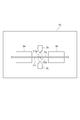
- FIG. 9 is a view of the end surface F2a of one of the optical fibers F2 as viewed from the front (in the direction of the optical axis).
- the arrows MSX and MSY in the figure indicate the imaging direction by the imaging unit 12, respectively. That is, in this example, at least two imaging units 12 are installed, and the two imaging units 12 image the end faces F1a and F2a from directions orthogonal to each other in the radial direction of the optical fibers F1 and F2.
- a light source for illuminating the optical fibers F1 and F2 is arranged at a position facing the imaging unit 12 with the optical fibers F1 and F2 interposed therebetween.
- the light source is, for example, a light emitting diode.
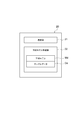
- FIG. 10 is a diagram schematically showing each of the imaging data PX and PY obtained by the imaging unit 12 that images images from the directions MSX and MSY.
- the positions and shapes of the optical fibers F1 and F2 are confirmed by the contours of the core CR and the clad CL.
- the core CR is brightened by the illumination light from the light source
- the clad CL is darkened by the refraction of the illumination light from the light source.
- FIG. 11 is a block diagram showing a functional configuration of the model creation device 20.
- FIG. 12 is a block diagram showing a hardware configuration of the model creation device 20.
- the model creation device 20 functionally includes a communication unit 21 and a discrimination model creation unit 22.
- the model creation device 20 is configured to include a computer including hardware such as a CPU 20a, a RAM 20b, a ROM 20c, an input device 20d, a communication module 20e, an auxiliary storage device 20f, and an output device 20g. NS.
- Each function of the model creation device 20 is realized by operating these components by a program or the like.
- the communication unit 21 shown in FIG. 11 is a portion that communicates with a plurality of fusion splicers 10 via an information communication network 30 (see FIG. 1) such as the Internet.
- the communication unit 21 receives information on the feature quantities extracted from the imaging data PX and PY and the types of the optical fibers F1 and F2 from the plurality of fusion splicers 10 via the information communication network 30.
- the communication unit 21 may receive the image pickup data PX, PY itself instead of the feature amount extracted from the image pickup data PX, PY. In that case, the model creation device 20 obtains the feature amount from the image pickup data PX, PY. Extract. Further, the information regarding the types of the optical fibers F1 and F2 may be only the information input by the user.
- the communication unit 21 receives information regarding the types of optical fibers F1 and F2 input by the user (by selecting one of the manufacturing conditions preset for each type of optical fiber, the corresponding type of optical fiber is used. (Including the case where the input is replaced with the input of the optical fiber itself) and the feature amount (or the imaging data itself) extracted from the imaging data PX and PY of the optical fibers F1 and F2 are received from each fusion splicer 10.
- the communication unit 21 uses these received information as sample data Da showing the correspondence between the feature quantities obtained from the imaged data PX and PY of the optical fibers F1 and F2 and the types of the optical fibers F1 and F2. It is provided to the preparation unit 22.
- the discrimination model creation unit 22 performs machine learning using the sample data Da provided by the communication unit 21 and creates a discrimination model Md for discriminating the types of the optical fibers F1 and F2 based on the imaging data PX and PY. do.
- Machine learning is preferably deep learning.
- various techniques included in so-called supervised learning such as a neural network and a support vector machine can be applied.
- the discrimination model creation unit 22 continuously performs machine learning using a huge amount of sample data Da obtained from a large number of fusion splicers 10 in operation to improve the accuracy of the discrimination model Md.
- the discrimination model creation unit 22 of the present embodiment classifies the plurality of fusion splicers 10 into two or more groups presumed to have similar tendencies of the imaging data PX and PY. Then, the discrimination model creation unit 22 collects sample data Da for each group and creates a discrimination model Md for each group. Creating a discrimination model Md for each group means that machine learning is performed using only sample data Da obtained from a plurality of fusion splicers 10 belonging to a certain group, and the created discrimination model Md belongs to the group. It means that it is provided only to the fusion splicer 10.
- Two or more groups presumed to have similar tendencies in the imaging data PX and PY are classified based on, for example, at least one of the following items (1) to (7).
- Similarity of inspection results of the fusion splicer 10 When the inspection results of the fusion splicer 10 and particularly the inspection results of the inspection items related to the imaging unit 12 are similar to each other in the plurality of fusion splicers 10, they are used. It is presumed that the tendencies of the imaging data PX and PY are similar in the fusion splicer 10. For example, the optical fiber that serves as a reference when inspecting each fusion splicer 10 is imaged by the imaging unit 12, and the brightness distribution and the like in the obtained imaging data PX and PY are similar to each other in the plurality of fusion splicers 10. For example, if you are doing so.
- Similarity of environmental conditions at the place where the fusion splicer 10 is used A plurality of environmental conditions (for example, at least one of temperature (air temperature), humidity, and atmospheric pressure) at the place where the fusion splicer 10 is used are fused.
- the fusion splicers 10 are similar to each other, it is presumed that the tendencies of the imaging data PX and PY are similar in those fusion splicers 10. Therefore, for example, a plurality of fusion splicers 10 used in a hot and humid area are grouped into one group, and a plurality of fusion splicers 10 used in a cold region are grouped into another group, and the highlands are combined. It is conceivable to classify the plurality of fusion splicers 10 used in the above into a further group.
- the deteriorated state of the fusion splicer 10 is, for example, the elapsed time from the manufacturing date, the usage time, the number of discharges, the connection frequency, the degree of dirt on the discharge electrode 3c, and the light source that illuminates the optical fiber from the opposite side of the imaging unit 12. It is at least one of the dimming state, the degree of dirt on the lens, and the device diagnosis result.
- optical fibers F1 and F2 which are mainly targeted to be connected in the field where the fusion splicer 10 is used, are similar to each other in the plurality of fusion splicers 10. If so, it is presumed that the tendencies of the imaging data PX and PY are similar in those fusion splicers 10.
- the types of optical fibers F1 and F2 referred to here refer to rough types of optical fibers such as single-mode fiber and multimode fiber, general-purpose fiber and distributed shift fiber, and the like.
- the discrimination model Md created by collecting the sample data Da for each group is transmitted to the fusion splicer 10 belonging to each corresponding group via the communication unit 21.
- the discrimination unit 14 of each fusion splicer 10 discriminates the types of each of the pair of optical fibers F1 and F2 by using the discrimination model Md corresponding to the group to which the fusion splicer 10 belongs.
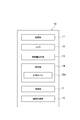
- FIG. 13 is a flowchart showing a method of fusion-bonding optical fibers according to the present embodiment. This method can be suitably realized by using the fusion splicing system 1A described above.
- the model creation step ST1 the optical fibers F1 and F2 to be connected by performing machine learning using the sample data Da showing the correspondence between the feature amount obtained from the imaging data of the optical fiber and the type of the optical fiber.
- a discrimination model Md for discriminating the types of the above based on the imaging data PX and PY of the optical fibers F1 and F2 is created.
- a plurality of fusion splicers 10 are classified into two or more groups presumed to have similar tendencies of imaging data PX and PY, and sample data Da is collected for each group.
- the imaging step ST2 a pair of optical fibers F1 and F2 are imaged to generate imaging data PX and PY.
- the discrimination step ST3 the feature amounts obtained from the image pickup data PX and PY generated in the imaging step ST2 are input to the discrimination model Md, and the types of the pair of optical fibers F1 and F2 are discriminated.
- the types of each of the pair of optical fibers F1 and F2 are discriminated by using the discrimination model Md corresponding to the group to which the fusion splicer 10 performing the discrimination step ST3 belongs.
- the connection step ST4 the pair of optical fibers F1 and F2 are fused and connected to each other under the connection conditions according to the combination of the types of the pair of optical fibers F1 and F2 based on the discrimination result in the discrimination step ST3. ..
- the fusion splicing system 1A, the fusion splicer 10, and the fusion splicing method of the present embodiment described above will be described.
- machine learning is performed using the sample data Da showing the correspondence between the feature amount obtained from the imaging data PX and PY of the optical fibers F1 and F2 and the types of the optical fibers F1 and F2, and the obtained discrimination is performed.
- the types of optical fibers F1 and F2 are discriminated using the model Md. Therefore, high-precision discrimination based on machine learning is possible.
- the plurality of fusion splicers 10 are classified into two or more groups presumed to have similar tendencies of the imaging data PX and PY, and sample data Da is collected for each group to create a discrimination model Md. .. Then, the types of each of the pair of optical fibers F1 and F2 are discriminated by using the discriminant model Md corresponding to the group to which the own machine belongs. As a result, machine learning can be performed only within the group in which the mechanical and structural variations of the imaging unit 12 are small, so that the accuracy of discriminating the optical fiber type based on the machine learning can be further improved.
- machine learning may be deep learning.
- the accuracy of discriminating the type of optical fiber can be further improved.
- the two or more groups may be classified based on the similarity of at least one of the inspection conditions and results of each fusion splicer 10.
- the similarity of the examination conditions and results is considered to affect the similarity of the tendency of the imaging data PX and PY. Therefore, in this case, the plurality of fusion splicers 10 can be appropriately classified into two or more groups presumed to have similar tendencies of the imaging data PX and PY.
- the above two or more groups are based on the similarity of the imaging data PX and PY obtained by imaging the optical fiber as a reference when inspecting each fusion splicer 10 by the imaging unit 12. It may be classified.
- the similarity of the imaging data PX and PY obtained by imaging the reference optical fiber at the time of inspection represents the similarity of the tendency of the imaging data PX and PY. Therefore, in this case, the plurality of fusion splicers 10 can be appropriately classified into two or more groups presumed to have similar tendencies of the imaging data PX and PY.
- the above two or more groups have similarities in environmental conditions (temperature, humidity, atmospheric pressure, etc.) when the optical fiber, which is a reference when inspecting each fusion splicer 10, is imaged by the imaging unit 12. It may be classified based on. It is considered that the similarity of the environmental conditions when the reference optical fiber is imaged at the time of inspection affects the similarity of the tendency of the imaging data PX and PY. Therefore, in this case, the plurality of fusion splicers 10 can be appropriately classified into two or more groups presumed to have similar tendencies of the imaging data PX and PY.
- the two or more groups may be classified based on the similarity of at least one of the manufacturer and the date and time of manufacture of each fusion splicer 10. It is considered that the similarity of at least one of the manufacturer and the date and time of manufacture of the fusion splicer 10 affects the similarity of the tendency of the imaging data PX and PY. Therefore, in this case, the plurality of fusion splicers 10 can be appropriately classified into two or more groups presumed to have similar tendencies of the imaging data PX and PY.
- the two or more groups may be classified based on the similarity of at least one of the manufacturer of the imaging unit 12 and the date and time of manufacture. It is considered that the similarity of at least one of the manufacturer and the date and time of manufacture of the imaging unit 12 affects the similarity of the tendency of the imaging data PX and PY. Therefore, in this case, the plurality of fusion splicers 10 can be appropriately classified into two or more groups presumed to have similar tendencies of the imaging data PX and PY.
- the above two or more groups may be classified based on the similarity of environmental conditions (temperature, humidity, atmospheric pressure, etc.) at the place of use of each fusion splicer 10. It is considered that the similarity of the environmental conditions at the place where the fusion splicer 10 is used affects the similarity of the tendency of the imaging data PX and PY. Therefore, in this case, the plurality of fusion splicers 10 can be appropriately classified into two or more groups presumed to have similar tendencies of the imaging data PX and PY.
- the above two or more groups may be classified based on the similarity of the deterioration states of each fusion splicer 10. It is considered that the similarity of the deteriorated state of the fusion splicer 10 affects the similarity of the tendency of the imaging data PX and PY. Therefore, in this case, the plurality of fusion splicers 10 can be appropriately classified into two or more groups presumed to have similar tendencies of the imaging data PX and PY.
- the above two or more groups may be classified based on the similarity of the types of optical fibers to be connected in each fusion splicer 10.
- the similarity of the types of optical fibers to be connected is considered to affect the similarity of the tendency of the imaging data PX and PY. Therefore, in this case, the plurality of fusion splicers 10 can be appropriately classified into two or more groups presumed to have similar tendencies of the imaging data PX and PY.
- the fusion splicing system for the optical fiber, the fusion splicer, and the method for fusion splicing the optical fiber according to the present disclosure are not limited to the above-described embodiment, and various other modifications are possible.
- the method of classifying two or more groups in which the tendency of the imaging data is presumed to be similar is not limited to that exemplified in the above embodiment.
- Output device 21 ... Communication unit 22 . Discrimination model creation unit 30 ... Information communication network CL ... Clad CR ... Core Da ... Sample data F1, F2 ... Optical fiber F1a, F2a ... End face Md ... Discrimination model MSX, MSY ... Direction PX, PY ... Imaging data ST1 ... Model creation process ST2 ... Imaging process ST3 ... Discrimination process ST4 ... Connection process
Landscapes
- Physics & Mathematics (AREA)
- Engineering & Computer Science (AREA)
- Plasma & Fusion (AREA)
- General Physics & Mathematics (AREA)
- Optics & Photonics (AREA)
- Mechanical Coupling Of Light Guides (AREA)
Abstract
融着接続システムは、モデル作成装置と複数の融着接続機とを備える。モデル作成装置は、光ファイバの撮像データから得られる特徴量と光ファイバの種類との対応関係を示すサンプルデータを用いて機械学習を行い、接続しようとする光ファイバの種類を光ファイバの撮像データに基づいて判別するための判別モデルを作成する。各融着接続機は、撮像部と判別部と接続部とを有する。撮像部は、一対の光ファイバを撮像して撮像データを生成する。判別部は、特徴量を判別モデルに入力して一対の光ファイバそれぞれの種類を判別する。接続部は、判別部における判別結果に基づいて、一対の光ファイバの種類の組み合わせに応じた接続条件にて一対の光ファイバを融着接続する。モデル作成装置は、複数の融着接続機を撮像データの傾向が類似していると推定される二以上のグループに分類して、グループ毎にサンプルデータを集めて判別モデルを作成する。
Description
本開示は、光ファイバのための融着接続システム、融着接続機、及び光ファイバを融着接続する方法に関する。
特許文献1及び特許文献2には、融着接続システム、融着接続機、及び光ファイバ種判別方法に関する技術が開示されている。
本開示の融着接続システムは、モデル作成装置と複数の融着接続機とを備える。モデル作成装置は、光ファイバの撮像データから得られる特徴量と前記光ファイバの種類との対応関係を示すサンプルデータを用いて機械学習を行い、接続しようとする光ファイバの種類を前記接続しようとする光ファイバの撮像データに基づいて判別するための判別モデルを作成する。複数の融着接続機のそれぞれは、撮像部と判別部と接続部とを有する。撮像部は、一対の光ファイバを撮像して撮像データを生成する。判別部は、撮像部から提供された撮像データから得られる特徴量を判別モデルに入力し、一対の光ファイバそれぞれの種類を判別する。接続部は、判別部における判別結果に基づいて、一対の光ファイバの種類の組み合わせに応じた接続条件にて一対の光ファイバを相互に融着接続する。モデル作成装置は、複数の融着接続機を撮像データの傾向が類似していると推定される二以上のグループに分類して、グループ毎にサンプルデータを集めて判別モデルを作成する。各融着接続機の判別部は、前記各融着接続機が属するグループに対応する判別モデルを用いて一対の光ファイバそれぞれの種類を判別する。
本開示の融着接続機は、撮像部と判別部と接続部とを備える。撮像部は、一対の光ファイバを撮像して撮像データを生成する。判別部は、接続しようとする光ファイバの種類を前記光ファイバの撮像データに基づいて判別するための判別モデルであって、光ファイバの撮像データから得られる特徴量と前記特徴量を得た光ファイバの種類との対応関係を示すサンプルデータを用いた機械学習により作成された判別モデルに、撮像部から提供された撮像データから得られる特徴量を入力し、一対の光ファイバそれぞれの種類を判別する。接続部は、判別部における判別結果に基づいて、一対の光ファイバの種類の組み合わせに応じた接続条件にて一対の光ファイバを相互に融着接続する。判別モデルは、複数の融着接続機を撮像データの傾向が類似していると推定される二以上のグループに分類して、グループ毎にサンプルデータを集めて作成されたものである。判別部は、当該融着接続機が属するグループに対応する判別モデルを用いて、一対の光ファイバそれぞれの種類を判別する。
本開示の光ファイバを融着接続する方法は、光ファイバの撮像データから得られる特徴量と前記光ファイバの種類との対応関係を示すサンプルデータを用いて機械学習を行い、接続しようとする光ファイバの種類を前記光ファイバの撮像データに基づいて判別するための判別モデルを作成する工程と、一対の光ファイバを撮像して撮像データを生成する工程と、撮像データを生成する工程において生成された撮像データから得られる特徴量を判別モデルに入力し、一対の光ファイバそれぞれの種類を判別する工程と、判別する工程における判別結果に基づいて、一対の光ファイバの種類の組み合わせに応じた接続条件にて一対の光ファイバを相互に融着接続する工程と、を含む。判別モデルを作成する工程では、撮像データを生成する工程、判別する工程、及び融着接続する工程を行う複数の融着接続機を、撮像データの傾向が類似していると推定される二以上のグループに分類して、複数の融着接続機からサンプルデータを集めて判別モデルをグループ毎に作成する。判別する工程では、前記判別する工程を行う融着接続機が属するグループに対応する判別モデルを用いて一対の光ファイバそれぞれの種類を判別する。
[本開示が解決しようとする課題]
光ファイバには様々な種類が存在する。光ファイバの種類は、例えば、シングルモードファイバ(SMF:Single Mode Fiber)、マルチモードファイバ(MMF:Multi Mode Fiber)、汎用シングルモードファイバ、分散シフト・シングルモードファイバ(DSF:Dispersion Shifted SMF)、及び非零分散シフト・シングルモードファイバ(NZDSF:Non-Zero DSF)、といった用途及び光学特性に関する特徴、並びに、光ファイバの直径、コア径、コア及びクラッドの材質、径方向の屈折率分布等の構造的な特徴によって区別される。そして、一対の光ファイバ同士を融着接続する際の最適な融着条件(放電時間、光ファイバ同士の相対位置等)は、一対の光ファイバの種類の組み合わせに応じて変化する。しかしながら、既に敷設された光ファイバの種類は不明であることが多い。したがって、接続対象である一対の光ファイバの種類の組み合わせを、融着接続機において正確に判別することが重要となる。
光ファイバには様々な種類が存在する。光ファイバの種類は、例えば、シングルモードファイバ(SMF:Single Mode Fiber)、マルチモードファイバ(MMF:Multi Mode Fiber)、汎用シングルモードファイバ、分散シフト・シングルモードファイバ(DSF:Dispersion Shifted SMF)、及び非零分散シフト・シングルモードファイバ(NZDSF:Non-Zero DSF)、といった用途及び光学特性に関する特徴、並びに、光ファイバの直径、コア径、コア及びクラッドの材質、径方向の屈折率分布等の構造的な特徴によって区別される。そして、一対の光ファイバ同士を融着接続する際の最適な融着条件(放電時間、光ファイバ同士の相対位置等)は、一対の光ファイバの種類の組み合わせに応じて変化する。しかしながら、既に敷設された光ファイバの種類は不明であることが多い。したがって、接続対象である一対の光ファイバの種類の組み合わせを、融着接続機において正確に判別することが重要となる。
例えば、特許文献1に記載されたシステムでは、光ファイバの径方向の輝度分布データから該光ファイバの種類を判別し得る判別モデルを、機械学習を用いて作成している。しかしながら、融着接続機が備える撮像装置には機械的・構造的なばらつきが存在するので、全く同一の光ファイバを撮像した場合であっても、得られる撮像データは融着接続機毎に僅かに異なる。したがって、複数の融着接続機から得られる撮像データに基づいて機械学習を行っても、判別の精度には限りがある。
そこで、本開示は、光ファイバ種類の判別精度を高めることができる光ファイバのための融着接続システム、融着接続機、及び光ファイバを融着接続する方法を提供することを目的とする。
[本開示の効果]
本開示によれば、光ファイバ種類の判別精度を高めることができる光ファイバのための融着接続システム、融着接続機、及び光ファイバを融着接続する方法を提供することが可能となる。
本開示によれば、光ファイバ種類の判別精度を高めることができる光ファイバのための融着接続システム、融着接続機、及び光ファイバを融着接続する方法を提供することが可能となる。
[本開示の実施形態の説明]
最初に、本開示の実施形態を列記して説明する。一実施形態に係る光ファイバのための融着接続システムは、光ファイバの撮像データから得られる特徴量と前記光ファイバの種類との対応関係を示すサンプルデータを用いて機械学習を行い、接続しようとする光ファイバの種類を前記接続しようとする光ファイバの撮像データに基づいて判別するための判別モデルを作成するモデル作成装置と、一対の光ファイバを撮像して撮像データを生成する撮像部、撮像部から提供された撮像データから得られる特徴量を判別モデルに入力し、一対の光ファイバそれぞれの種類を判別する判別部、及び、判別部における判別結果に基づいて、一対の光ファイバの種類の組み合わせに応じた接続条件にて一対の光ファイバを相互に融着接続する接続部を有する複数の融着接続機と、を備える。モデル作成装置は、複数の融着接続機を二以上のグループに分類してグループ毎にサンプルデータを集めて判別モデルを作成する。各融着接続機の判別部は、前記各融着接続機が属するグループに対応する判別モデルを用いて一対の光ファイバそれぞれの種類を判別する。
最初に、本開示の実施形態を列記して説明する。一実施形態に係る光ファイバのための融着接続システムは、光ファイバの撮像データから得られる特徴量と前記光ファイバの種類との対応関係を示すサンプルデータを用いて機械学習を行い、接続しようとする光ファイバの種類を前記接続しようとする光ファイバの撮像データに基づいて判別するための判別モデルを作成するモデル作成装置と、一対の光ファイバを撮像して撮像データを生成する撮像部、撮像部から提供された撮像データから得られる特徴量を判別モデルに入力し、一対の光ファイバそれぞれの種類を判別する判別部、及び、判別部における判別結果に基づいて、一対の光ファイバの種類の組み合わせに応じた接続条件にて一対の光ファイバを相互に融着接続する接続部を有する複数の融着接続機と、を備える。モデル作成装置は、複数の融着接続機を二以上のグループに分類してグループ毎にサンプルデータを集めて判別モデルを作成する。各融着接続機の判別部は、前記各融着接続機が属するグループに対応する判別モデルを用いて一対の光ファイバそれぞれの種類を判別する。
一実施形態に係る融着接続機は、一対の光ファイバを撮像して撮像データを生成する撮像部と、接続しようとする光ファイバの種類を前記接続しようとする光ファイバの撮像データに基づいて判別するための判別モデルであって、光ファイバの撮像データから得られる特徴量と前記特徴量を得た光ファイバの種類との対応関係を示すサンプルデータを用いた機械学習により作成された判別モデルに、撮像部から提供された撮像データから得られる特徴量を入力し、一対の光ファイバそれぞれの種類を判別する判別部と、判別部における判別結果に基づいて、一対の光ファイバの種類の組み合わせに応じた接続条件にて一対の光ファイバを相互に融着接続する接続部と、を備える。判別モデルは、複数の融着接続機を二以上のグループに分類してグループ毎にサンプルデータを集めて作成されたものである。判別部は、当該融着接続機が属するグループに対応する判別モデルを用いて一対の光ファイバそれぞれの種類を判別する。
一実施形態に係る光ファイバを融着接続する方法は、光ファイバの撮像データから得られる特徴量と前記光ファイバの種類との対応関係を示すサンプルデータを用いて機械学習を行い、接続しようとする光ファイバの種類を前記接続しようとする光ファイバの撮像データに基づいて判別するための判別モデルを作成する工程と、一対の光ファイバを撮像して撮像データを生成する工程と、撮像データを生成する工程において生成された撮像データから得られる特徴量を判別モデルに入力し、一対の光ファイバそれぞれの種類を判別する工程と、判別する工程における判別結果に基づいて、一対の光ファイバの種類の組み合わせに応じた接続条件にて一対の光ファイバを相互に融着接続する工程と、を含む。判別モデルを作成する工程では、撮像データを生成する工程、判別する工程、及び融着接続する工程を行う複数の融着接続機を、撮像データの傾向が類似していると推定される二以上のグループに分類して、複数の融着接続機からサンプルデータを集めて判別モデルをグループ毎に作成する。判別する工程では、前記判別する工程を行う融着接続機が属するグループに対応する判別モデルを用いて一対の光ファイバそれぞれの種類を判別する。
上記の融着接続システム、融着接続機、及び融着接続する方法では、光ファイバの撮像データから得られる特徴量と前記特徴量を得た光ファイバの種類との対応関係を示すサンプルデータを用いて機械学習を行い、得られた判別モデルを用いて光ファイバの種類を判別する。したがって、機械学習に基づく高精度の判別が可能となる。更に、複数の融着接続機を、撮像データの傾向が類似していると推定される二以上のグループに分類し、グループ毎にサンプルデータを集めて判別モデルを作成する。そして、自機が属するグループに対応する判別モデルを用いて、一対の光ファイバそれぞれの種類を判別する。これにより、撮像部の機械的・構造的なばらつきが少ないグループ内に限定して機械学習を行うことができるので、機械学習に基づく光ファイバ種類の判別精度を更に高めることができる。
上記の融着接続システム、融着接続機、及び融着接続する方法において、機械学習は深層学習であってもよい。この場合、光ファイバ種類の判別精度を更に高めることができる。
上記の融着接続システム、融着接続機、及び融着接続する方法において、二以上のグループは、各融着接続機の検査の条件及び各融着接続機の検査の結果のうち少なくとも一方の類似性に基づいて分類されてもよい。検査の条件及び検査の結果の類似性は、撮像データの傾向の類似性に影響すると考えられる。したがって、この場合、複数の融着接続機を、撮像データの傾向が類似していると推定される二以上のグループに適切に分類することができる。
上記の融着接続システム、融着接続機、及び融着接続する方法において、二以上のグループは、各融着接続機の検査の際に基準となる光ファイバを撮像部により撮像して得られた撮像データの類似性に基づいて分類されてもよい。検査の際に基準となる光ファイバを撮像して得られた撮像データの類似性は、撮像データの傾向の類似性を表す。したがって、この場合、複数の融着接続機を、撮像データの傾向が類似していると推定される二以上のグループに適切に分類することができる。
上記の融着接続システム、融着接続機、及び融着接続する方法において、二以上のグループは、各融着接続機の検査の際に基準となる光ファイバを撮像部により撮像した際の環境条件の類似性に基づいて分類されてもよい。検査の際に基準となる光ファイバを撮像した際の環境条件の類似性は、撮像データの傾向の類似性に影響すると考えられる。したがって、この場合、複数の融着接続機を、撮像データの傾向が類似していると推定される二以上のグループに適切に分類することができる。
上記の融着接続システム、融着接続機、及び融着接続する方法において、二以上のグループは、各融着接続機の製造者及び製造日時のうち少なくとも一方の類似性に基づいて分類されてもよい。融着接続機の製造者及び製造日時のうち少なくとも一方の類似性は、撮像データの傾向の類似性に影響すると考えられる。したがって、この場合、複数の融着接続機を、撮像データの傾向が類似していると推定される二以上のグループに適切に分類することができる。
上記の融着接続システム、融着接続機、及び融着接続する方法において、二以上のグループは、各融着接続機の撮像部の製造者及び製造日時のうち少なくとも一方の類似性に基づいて分類されてもよい。撮像部の製造者及び製造日時のうち少なくとも一方の類似性は、撮像データの傾向の類似性に影響すると考えられる。したがって、この場合、複数の融着接続機を、撮像データの傾向が類似していると推定される二以上のグループに適切に分類することができる。
上記の融着接続システム、融着接続機、及び融着接続する方法において、二以上のグループは、各融着接続機の使用場所における環境条件の類似性に基づいて分類されてもよい。融着接続機の使用場所における環境条件の類似性は、撮像データの傾向の類似性に影響すると考えられる。したがって、この場合、複数の融着接続機を、撮像データの傾向が類似していると推定される二以上のグループに適切に分類することができる。
上記の融着接続システム、融着接続機、及び融着接続する方法において、二以上のグループは、各融着接続機の劣化状態の類似性に基づいて分類されてもよい。融着接続機の劣化状態の類似性は、撮像データの傾向の類似性に影響すると考えられる。したがって、この場合、複数の融着接続機を、撮像データの傾向が類似していると推定される二以上のグループに適切に分類することができる。
上記の融着接続システム、融着接続機、及び融着接続する方法において、二以上のグループは、各融着接続機において接続対象とされる光ファイバ種類の類似性に基づいて分類されてもよい。接続対象とされる光ファイバ種類の類似性は、撮像データの傾向の類似性に影響すると考えられる。したがって、この場合、複数の融着接続機を、撮像データの傾向が類似していると推定される二以上のグループに適切に分類することができる。
[本開示の実施形態の詳細]
本開示の、光ファイバのための融着接続システム、融着接続機、及び光ファイバを融着接続する方法の具体例を、以下に図面を参照しつつ説明する。なお、本発明はこれらの例示に限定されるものではなく、請求の範囲によって示され、請求の範囲と均等の意味及び範囲内でのすべての変更が含まれることが意図される。以下の説明では、図面の説明において同一の要素には同一の符号を付し、重複する説明を省略する。
本開示の、光ファイバのための融着接続システム、融着接続機、及び光ファイバを融着接続する方法の具体例を、以下に図面を参照しつつ説明する。なお、本発明はこれらの例示に限定されるものではなく、請求の範囲によって示され、請求の範囲と均等の意味及び範囲内でのすべての変更が含まれることが意図される。以下の説明では、図面の説明において同一の要素には同一の符号を付し、重複する説明を省略する。
図1は、本開示の一実施形態に係る融着接続システム1Aの構成を概略的に示す図である。この融着接続システム1Aは、複数の融着接続機10と、モデル作成装置20とを備える。融着接続機10は、光ファイバの融着接続を行う装置である。モデル作成装置20は、光ファイバの種類を判別するための判別モデルを作成する装置である。モデル作成装置20は、情報通信網30を介して複数の融着接続機10と通信可能なコンピュータである。情報通信網30は、例えばインターネットである。モデル作成装置20の所在地域と、融着接続機10の所在地域とは互いに離れている。
図2及び図3は、融着接続機10の外観を示す斜視図である。図2は風防カバーが閉じている状態の外観を示し、図3は風防カバーが開けられて融着接続機10の内部構造が見える状態の外観を示す。図2及び図3に示すように、融着接続機10は箱状の筐体2を備えている。この筐体2の上部には、光ファイバ同士を融着接続するための接続部3と、加熱器4とが設けられている。加熱器4は、接続部3において融着接続された光ファイバ同士の接続部分に被せられたファイバ補強スリーブを加熱収縮させる部分である。融着接続機10は、筐体2の内部に配置された撮像部(後述)によって撮像された光ファイバ同士の融着接続状況を表示するモニタ5を備えている。さらに、融着接続機10は、接続部3への風の進入を防止するための風防カバー6を備えている。
接続部3は、一対の光ファイバホルダ3aを載置可能なホルダ載置部と、一対のファイバ位置決め部3bと、一対の放電電極3cとを有している。融着対象の光ファイバそれぞれは光ファイバホルダ3aに保持固定され、光ファイバホルダ3aはそれぞれホルダ載置部に載置固定される。ファイバ位置決め部3bは、一対の光ファイバホルダ3aの間に配置され、光ファイバホルダ3aのそれぞれに保持された光ファイバの先端部を位置決めする。放電電極3cは、アーク放電によって光ファイバの先端同士を融着するための電極であって、一対のファイバ位置決め部3bの間に配置されている。
風防カバー6は、接続部3を開閉自在に覆うように筐体2に連結されている。風防カバー6の側面6aのそれぞれには、接続部3へ(すなわち光ファイバホルダ3aのそれぞれへ)光ファイバを導入するための導入口6bが形成されている。
図4は、融着接続機10の機能的な構成を示すブロック図である。図5は、融着接続機10のハードウェア構成を示すブロック図である。図4に示すように、融着接続機10は、機能的には、接続部3、通信部11、撮像部(カメラ)12、特徴量抽出部13、判別部14、及び融着制御部15を備える。融着接続機10は、図5に示すように、その制御部として、CPU10a、RAM10b、ROM10c、入力装置10d、補助記憶装置10e、及び出力装置10f等のハードウェアを備えるコンピュータを含むものとして構成される。これらの構成要素がプログラム等により動作することにより、融着接続機10の各機能が実現される。また、制御部におけるこれらの要素は、前述した接続部3、モニタ5、通信部11としての無線通信モジュール、及び撮像部12と電気的に接続されている。入力装置10dは、モニタ5に一体として設けられたタッチパネルを含んでもよい。
通信部11は、例えば、無線LANモジュールにより構成され、インターネット等の情報通信網30を介して、モデル作成装置20との間で各種データの送受信を行う。撮像部12は、接続対象である光ファイバを互いに対向した状態で光ファイバの径方向から撮像し、撮像データを生成する。特徴量抽出部13は、撮像部12から得られる撮像データから、光ファイバの種類を特定するための二以上の特徴量を抽出する。特徴量は、例えば、光ファイバの径方向における輝度分布、光ファイバの外径、コアの外径、コア外径と光ファイバの外径の比、光ファイバのコアとクラッドの面積の割合、光ファイバの輝度の総和、光ファイバの断面内における輝度分布の変曲点位置や数、光ファイバのコア部とクラッド部の輝度差、特定の輝度以上となるコア部の幅等である。
判別部14は、光ファイバの種類を判別するための判別モデルMdを記憶して保持している。判別部14は、特徴量抽出部13から得られる特徴量を判別モデルMdに入力し、一対の光ファイバそれぞれの種類を判別する。判別部14による判別結果は、モニタ5に表示される。使用者は、モニタ5に表示された一対の光ファイバそれぞれの種類が誤りである場合、正しい種類を入力装置10dを介して入力し、判別結果を訂正する。或いは、使用者は、判別部14による判別結果に関わりなく、一対の光ファイバそれぞれの種類を入力装置10dを介して入力してもよい。その場合、使用者による入力が優先して採用され、光ファイバそれぞれの種類が特定される。或いは、光ファイバの種類ごとに予め設定された製造条件の一を選択することで、対応する光ファイバの種類そのものの入力に代えても良い。
融着制御部15は、接続部3の動作を制御する。すなわち、融着制御部15は、使用者によるスイッチの操作を受けて、接続部3における光ファイバの先端同士の当接動作およびアーク放電を制御する。光ファイバの先端同士の当接動作には、ファイバ位置決め部3bによる光ファイバの位置決め処理、すなわち各光ファイバの先端位置の制御が含まれる。また、アーク放電の制御には、放電パワー、放電開始タイミング及び放電終了タイミングの制御が含まれる。光ファイバの先端位置及び放電パワーといった各種の接続条件は、一対の光ファイバの種類の組み合わせ毎に予め設定されており、例えばROM10cに格納されている。融着制御部15は、判別部14によって判別された、又は使用者によって入力された一対の光ファイバの種類の組み合わせに応じて、接続条件を選択する。したがって、接続部3は、判別部14における判別結果又は使用者による入力結果に基づいて、一対の光ファイバの種類の組み合わせに応じた接続条件にて、一対の光ファイバを相互に融着接続する。
接続部3の動作は次のとおりである。まず、図6に示されるように、使用者が、接続対象である一対の光ファイバF1及びF2を、それぞれ光ファイバホルダ3aに保持させる。このとき、光ファイバF1の端面F1aと、光ファイバF2の端面F2aとが、互いに対向して配置される。次に、使用者が、融着接続機10に融着接続の開始を指示する。この指示は、例えばスイッチ入力を介して行われる。この指示を受けて、図7に示すように、融着制御部15が、接続条件として設定された端面F1a,F2aの位置に基づいて、光ファイバF1,F2の位置決めを行う。その後、図8に示すように、融着制御部15が、一対の放電電極3c間のアーク放電を開始する。
アーク放電の開始直後は、端面F1a,F2aが互いに離れており、該アーク放電は、端面F1a,F2aを融着前に予め軟化させるための予備放電に相当する。アーク放電が開始されると、融着制御部15は、ファイバ位置決め部3bの位置を制御することにより、端面F1a,F2aを互いに近づけ、互いに当接させる。そして、アーク放電を継続することにより(本放電)、端面F1a,F2aが更に軟化し、互いに融着する。
本実施形態において、接続条件には、放電開始前における各端面F1a,F2aの位置、放電開始前における各端面F1a,F2a同士の間隔、予備放電時間、本放電時間、各端面F1a,F2a同士が接した後の押し込み量、各端面F1a,F2a同士を押し込んだ後の引き戻し量、予備放電パワー、本放電パワー、及び引戻し時の放電パワーのうち少なくとも一つが含まれる。
放電開始前における各端面F1a,F2aの位置とは、図6に示された状態、すなわち予備放電の開始時点における、一対の放電電極の中心軸を結ぶ線(放電中心軸)を基準とした各端面F1a,F2aの位置をいう。これらの端面位置に応じて、放電中心と各端面F1a,F2aとの距離が変わることにより加熱量(溶融量)が増減し、また端面F1a,F2a同士が当接するまでの移動に要する時間が変化する。放電開始前における各端面F1a,F2a同士の間隔とは、図6に示された状態、すなわち予備放電の開始時点における端面F1a,F2a同士の間隔をいう。この間隔に応じて、端面F1a,F2a同士が当接するまでの移動に要する時間が変化する。予備放電時間とは、図6に示された状態でアーク放電を開始してから、端面F1a,F2a同士を当接させるために光ファイバF1,F2の相対的な移動を開始するまでの時間をいう。本放電時間とは、端面F1a,F2a同士が当接してから、アーク放電を終了する(言い換えると、一対の放電電極3cへの電圧の印加を停止する)までの時間をいう。なお、予備放電と本放電とは、時間的に連続して行われる。各端面F1a,F2a同士が接した後の押し込み量とは、図6に示された状態から光ファイバF1,F2を相対的に移動させて端面F1a,F2a同士を当接させてから、放電中において更に同じ向きに光ファイバF1,F2を相対的に移動させる際の移動距離をいう。各端面F1a,F2a同士を押し込んだ後の引き戻し量とは、端面F1a,F2a同士を当接させた後、更に端面F1a,F2aを押し込んでから、融着接続中において逆向き(端面F1a,F2a同士が離れる向き)に光ファイバF1,F2を相対的に移動させる際の移動距離をいう。予備放電パワーとは、図6に示された状態でアーク放電を開始してから、端面F1a,F2a同士を当接させるために光ファイバF1,F2の相対的な移動を開始するまでの期間におけるアーク放電パワーをいう。
ここで、図9は、一方の光ファイバF2の端面F2aを正面(光軸方向)から見た図である。図中の矢印MSX及びMSYは、それぞれ撮像部12による撮像方向を示している。すなわち、この例では撮像部12が少なくとも2個設置され、2つの撮像部12が、光ファイバF1,F2の径方向であって互いに直交する方向から各端面F1a,F2aを撮像する。光ファイバF1,F2を挟んで撮像部12と対向する位置には、光ファイバF1,F2を照明するための光源が配置される。光源は例えば発光ダイオードである。
図10は、方向MSX,MSYそれぞれから撮像する撮像部12において得られる撮像データPX,PYそれぞれを模式的に示す図である。図10に示されるように、これらの撮像データPX,PYにおいて、光ファイバF1,F2の位置及び形状は、コアCR及びクラッドCLの輪郭により確認される。コアCRは、光源からの照明光によって明るくなり、クラッドCLは、光源からの照明光の屈折により暗くなる。
図11は、モデル作成装置20の機能的な構成を示すブロック図である。図12は、モデル作成装置20のハードウェア構成を示すブロック図である。図11に示すように、モデル作成装置20は、機能的には、通信部21及び判別モデル作成部22を備える。モデル作成装置20は、図12に示されるように、CPU20a、RAM20b、ROM20c、入力装置20d、通信モジュール20e、補助記憶装置20f、及び出力装置20g等のハードウェアを備えるコンピュータを含むものとして構成される。これらの構成要素がプログラム等により動作することによって、モデル作成装置20の各機能が実現される。
図11に示される通信部21は、インターネット等の情報通信網30(図1を参照)を介して複数の融着接続機10との間で通信を行う部分である。通信部21は、情報通信網30を介して、複数の融着接続機10から、撮像データPX,PYから抽出された特徴量、及び光ファイバF1,F2の種類に関する情報を受信する。通信部21は、撮像データPX,PYから抽出された特徴量に代えて、撮像データPX,PYそのものを受信してもよく、その場合、モデル作成装置20において撮像データPX,PYから特徴量を抽出する。また、光ファイバF1,F2の種類に関する情報は、使用者によって入力された情報のみであってもよい。言い換えると、通信部21は、使用者によって入力された光ファイバF1,F2の種類に関する情報(光ファイバの種類ごとに予め設定された製造条件の一を選択することで、対応する光ファイバの種類そのものの入力に代えた場合も含む)と、前記光ファイバF1,F2の撮像データPX,PYから抽出された特徴量(又は撮像データそのもの)を、各融着接続機10から受信する。通信部21は、受信したこれらの情報を、光ファイバF1,F2の撮像データPX,PYから得られる特徴量と、光ファイバF1,F2の種類との対応関係を示すサンプルデータDaとして、判別モデル作成部22に提供する。
判別モデル作成部22は、通信部21から提供されたサンプルデータDaを用いて機械学習を行い、撮像データPX,PYに基づいて光ファイバF1,F2の種類を判別するための判別モデルMdを作成する。機械学習は、好ましくは深層学習(ディープラーニング)である。機械学習の技法としては、例えばニューラルネットワーク、サポートベクターマシン等、いわゆる教師あり学習に含まれる様々な技法を適用できる。判別モデル作成部22は、稼働中である多数の融着接続機10から得られる膨大なサンプルデータDaを用いて機械学習を継続的に行い、判別モデルMdの精度を高める。また、本実施形態の判別モデル作成部22は、複数の融着接続機10を、撮像データPX,PYの傾向が類似していると推定される二以上のグループに分類する。そして、判別モデル作成部22は、グループ毎にサンプルデータDaを集めて、判別モデルMdをグループ毎に作成する。判別モデルMdをグループ毎に作成するとは、或るグループに属する複数の融着接続機10から得られるサンプルデータDaのみを用いて機械学習を行い、作成された判別モデルMdを、当該グループに属する融着接続機10のみに提供することを意味する。
撮像データPX,PYの傾向が類似していると推定される二以上のグループは、例えば下記の項目(1)から(7)のうち少なくとも1つに基づいて分類される。
(1)融着接続機10の検査結果の類似性
融着接続機10の検査結果、特に撮像部12に関する検査項目における検査結果が複数の融着接続機10において互いに類似している場合、それらの融着接続機10においては撮像データPX,PYの傾向が類似していると推定される。例えば、各融着接続機10の検査の際に基準となる光ファイバを撮像部12により撮像し、得られた撮像データPX,PYにおける輝度分布等が、複数の融着接続機10において互いに類似している場合等である。
融着接続機10の検査結果、特に撮像部12に関する検査項目における検査結果が複数の融着接続機10において互いに類似している場合、それらの融着接続機10においては撮像データPX,PYの傾向が類似していると推定される。例えば、各融着接続機10の検査の際に基準となる光ファイバを撮像部12により撮像し、得られた撮像データPX,PYにおける輝度分布等が、複数の融着接続機10において互いに類似している場合等である。
(2)融着接続機10の検査条件の類似性
融着接続機10の検査条件、特に撮像部12に関する検査項目における検査条件が複数の融着接続機10において互いに類似している場合、それらの融着接続機10においては撮像データPX,PYの傾向が類似していると推定される。例えば、各融着接続機10の検査の際に基準となる光ファイバを撮像部12により撮像した際の環境条件(例えば、温度(気温)、湿度、及び気圧のうち少なくとも1つ)が、複数の融着接続機10において互いに類似している場合等である。
融着接続機10の検査条件、特に撮像部12に関する検査項目における検査条件が複数の融着接続機10において互いに類似している場合、それらの融着接続機10においては撮像データPX,PYの傾向が類似していると推定される。例えば、各融着接続機10の検査の際に基準となる光ファイバを撮像部12により撮像した際の環境条件(例えば、温度(気温)、湿度、及び気圧のうち少なくとも1つ)が、複数の融着接続機10において互いに類似している場合等である。
(3)融着接続機10の製造者及び製造日時の類似性
融着接続機10の製造者及び製造日時のうち少なくとも一方が複数の融着接続機10において互いに類似している場合、それらの融着接続機10においては撮像データPX,PYの傾向が類似していると推定される。なお、製造日時が類似しているとは、例えばロットが同じであることを意味してもよい。また、製造者が類似しているとは、例えば同じ製造者又は同じ工場において製造されたことを意味してもよい。
融着接続機10の製造者及び製造日時のうち少なくとも一方が複数の融着接続機10において互いに類似している場合、それらの融着接続機10においては撮像データPX,PYの傾向が類似していると推定される。なお、製造日時が類似しているとは、例えばロットが同じであることを意味してもよい。また、製造者が類似しているとは、例えば同じ製造者又は同じ工場において製造されたことを意味してもよい。
(4)撮像部12の製造者及び製造日時の類似性
撮像部12の製造者及び製造日時のうち少なくとも一方が複数の融着接続機10において互いに類似している場合、それらの融着接続機10においては撮像データPX,PYの傾向が類似していると推定される。なお、製造日時が類似しているとは、例えばロットが同じであることを意味してもよい。また、製造者が類似しているとは、例えば同じ製造者又は同じ工場において製造されたことを意味してもよい。
撮像部12の製造者及び製造日時のうち少なくとも一方が複数の融着接続機10において互いに類似している場合、それらの融着接続機10においては撮像データPX,PYの傾向が類似していると推定される。なお、製造日時が類似しているとは、例えばロットが同じであることを意味してもよい。また、製造者が類似しているとは、例えば同じ製造者又は同じ工場において製造されたことを意味してもよい。
(5)融着接続機10の使用場所における環境条件の類似性
融着接続機10の使用場所における環境条件(例えば、温度(気温)、湿度、及び気圧のうち少なくとも1つ)が複数の融着接続機10において互いに類似している場合、それらの融着接続機10においては撮像データPX,PYの傾向が類似していると推定される。したがって、例えば、高温多湿地域において使用されている複数の融着接続機10をまとめて1つのグループとし、寒冷地域において使用されている複数の融着接続機10をまとめて別のグループとし、高地において使用されている複数の融着接続機10をまとめて更に別のグループとする等の分類が考えられる。
融着接続機10の使用場所における環境条件(例えば、温度(気温)、湿度、及び気圧のうち少なくとも1つ)が複数の融着接続機10において互いに類似している場合、それらの融着接続機10においては撮像データPX,PYの傾向が類似していると推定される。したがって、例えば、高温多湿地域において使用されている複数の融着接続機10をまとめて1つのグループとし、寒冷地域において使用されている複数の融着接続機10をまとめて別のグループとし、高地において使用されている複数の融着接続機10をまとめて更に別のグループとする等の分類が考えられる。
(6)融着接続機10の劣化状態の類似性
融着接続機10の劣化状態が複数の融着接続機10において互いに類似している場合、それらの融着接続機10においては撮像データPX,PYの傾向が類似していると推定される。融着接続機10の劣化状態とは、例えば、製造日からの経過時間、使用時間、放電回数、接続頻度、放電電極3cの汚れ具合、撮像部12の反対側から光ファイバを照明する光源の調光状態、レンズの汚れ具合、及び機器診断結果のうち少なくとも1つである。
融着接続機10の劣化状態が複数の融着接続機10において互いに類似している場合、それらの融着接続機10においては撮像データPX,PYの傾向が類似していると推定される。融着接続機10の劣化状態とは、例えば、製造日からの経過時間、使用時間、放電回数、接続頻度、放電電極3cの汚れ具合、撮像部12の反対側から光ファイバを照明する光源の調光状態、レンズの汚れ具合、及び機器診断結果のうち少なくとも1つである。
(7)接続対象光ファイバの種類の類似性
融着接続機10が使用される現場において主に接続対象とされている光ファイバF1,F2の種類が、複数の融着接続機10において互いに類似している場合、それらの融着接続機10においては撮像データPX,PYの傾向が類似していると推定される。ここでいう光ファイバF1,F2の種類とは、例えばシングルモードファイバとマルチモードファイバ、或いは汎用ファイバと分散シフトファイバ等といった、光ファイバの大まかな種類を指す。
融着接続機10が使用される現場において主に接続対象とされている光ファイバF1,F2の種類が、複数の融着接続機10において互いに類似している場合、それらの融着接続機10においては撮像データPX,PYの傾向が類似していると推定される。ここでいう光ファイバF1,F2の種類とは、例えばシングルモードファイバとマルチモードファイバ、或いは汎用ファイバと分散シフトファイバ等といった、光ファイバの大まかな種類を指す。
こうしてグループ毎にサンプルデータDaを集めて作成された判別モデルMdは、通信部21を介して、それぞれ対応するグループに属する融着接続機10に送信される。各融着接続機10の判別部14は、当該融着接続機10が属するグループに対応する判別モデルMdを用いて、一対の光ファイバF1,F2それぞれの種類を判別する。
図13は、本実施形態に係る、光ファイバを融着接続する方法を示すフローチャートである。この方法は、上述した融着接続システム1Aを用いて好適に実現され得る。まず、モデル作成工程ST1として、光ファイバの撮像データから得られる特徴量と当該光ファイバの種類との対応関係を示すサンプルデータDaを用いて機械学習を行い、接続しようとする光ファイバF1,F2の種類を光ファイバF1,F2の撮像データPX,PYに基づいて判別するための判別モデルMdを作成する。このモデル作成工程ST1では、複数の融着接続機10を、撮像データPX,PYの傾向が類似していると推定される二以上のグループに分類して、グループ毎にサンプルデータDaを集めて判別モデルMdを作成する。次に、撮像工程ST2として、一対の光ファイバF1,F2を撮像して撮像データPX,PYを生成する。続いて、判別工程ST3として、撮像工程ST2において生成された撮像データPX,PYから得られる特徴量を判別モデルMdに入力し、一対の光ファイバF1,F2それぞれの種類を判別する。この判別工程ST3では、当該判別工程ST3を行う融着接続機10が属するグループに対応する判別モデルMdを用いて、一対の光ファイバF1,F2それぞれの種類を判別する。続いて、接続工程ST4として、判別工程ST3における判別結果に基づいて、一対の光ファイバF1,F2の種類の組み合わせに応じた接続条件にて一対の光ファイバF1,F2を相互に融着接続する。
以上に説明した本実施形態の融着接続システム1A、融着接続機10、及び融着接続する方法によって得られる効果について説明する。本実施形態では、光ファイバF1,F2の撮像データPX,PYから得られる特徴量と光ファイバF1,F2の種類との対応関係を示すサンプルデータDaを用いて機械学習を行い、得られた判別モデルMdを用いて光ファイバF1,F2の種類を判別する。したがって、機械学習に基づく高精度の判別が可能となる。更に、複数の融着接続機10を、撮像データPX,PYの傾向が類似していると推定される二以上のグループに分類し、グループ毎にサンプルデータDaを集めて判別モデルMdを作成する。そして、自機が属するグループに対応する判別モデルMdを用いて、一対の光ファイバF1,F2それぞれの種類を判別する。これにより、撮像部12の機械的・構造的なばらつきが少ないグループ内に限定して機械学習を行うことができるので、機械学習に基づく光ファイバ種類の判別精度を更に高めることができる。
前述したように、機械学習は深層学習であってもよい。この場合、光ファイバ種類の判別精度を更に高めることができる。
前述したように、上記二以上のグループは、各融着接続機10の検査の条件及び結果のうち少なくとも一方の類似性に基づいて分類されてもよい。検査の条件及び結果の類似性は、撮像データPX,PYの傾向の類似性に影響すると考えられる。したがって、この場合、複数の融着接続機10を、撮像データPX,PYの傾向が類似していると推定される二以上のグループに適切に分類することができる。
前述したように、上記二以上のグループは、各融着接続機10の検査の際に基準となる光ファイバを撮像部12により撮像して得られた撮像データPX,PYの類似性に基づいて分類されてもよい。検査の際に基準となる光ファイバを撮像して得られた撮像データPX,PYの類似性は、撮像データPX,PYの傾向の類似性を表す。したがって、この場合、複数の融着接続機10を、撮像データPX,PYの傾向が類似していると推定される二以上のグループに適切に分類することができる。
前述したように、上記二以上のグループは、各融着接続機10の検査の際に基準となる光ファイバを撮像部12により撮像した際の環境条件(温度、湿度、気圧等)の類似性に基づいて分類されてもよい。検査の際に基準となる光ファイバを撮像した際の環境条件の類似性は、撮像データPX,PYの傾向の類似性に影響すると考えられる。したがって、この場合、複数の融着接続機10を、撮像データPX,PYの傾向が類似していると推定される二以上のグループに適切に分類することができる。
前述したように、上記二以上のグループは、各融着接続機10の製造者及び製造日時のうち少なくとも一方の類似性に基づいて分類されてもよい。融着接続機10の製造者及び製造日時のうち少なくとも一方の類似性は、撮像データPX,PYの傾向の類似性に影響すると考えられる。したがって、この場合、複数の融着接続機10を、撮像データPX,PYの傾向が類似していると推定される二以上のグループに適切に分類することができる。
前述したように、上記二以上のグループは、撮像部12の製造者及び製造日時のうち少なくとも一方の類似性に基づいて分類されてもよい。撮像部12の製造者及び製造日時のうち少なくとも一方の類似性は、撮像データPX,PYの傾向の類似性に影響すると考えられる。したがって、この場合、複数の融着接続機10を、撮像データPX,PYの傾向が類似していると推定される二以上のグループに適切に分類することができる。
前述したように、上記二以上のグループは、各融着接続機10の使用場所における環境条件(温度、湿度、気圧等)の類似性に基づいて分類されてもよい。融着接続機10の使用場所における環境条件の類似性は、撮像データPX,PYの傾向の類似性に影響すると考えられる。したがって、この場合、複数の融着接続機10を、撮像データPX,PYの傾向が類似していると推定される二以上のグループに適切に分類することができる。
前述したように、上記二以上のグループは、各融着接続機10の劣化状態の類似性に基づいて分類されてもよい。融着接続機10の劣化状態の類似性は、撮像データPX,PYの傾向の類似性に影響すると考えられる。したがって、この場合、複数の融着接続機10を、撮像データPX,PYの傾向が類似していると推定される二以上のグループに適切に分類することができる。
前述したように、上記二以上のグループは、各融着接続機10において接続対象とされる光ファイバ種類の類似性に基づいて分類されてもよい。接続対象とされる光ファイバ種類の類似性は、撮像データPX,PYの傾向の類似性に影響すると考えられる。したがって、この場合、複数の融着接続機10を、撮像データPX,PYの傾向が類似していると推定される二以上のグループに適切に分類することができる。
本開示による光ファイバのための融着接続システム、融着接続機、及び光ファイバを融着接続する方法は、上述した実施形態に限られるものではなく、他に様々な変形が可能である。例えば、撮像データの傾向が類似していると推定される二以上のグループの分類方法は、上記実施形態に例示されたものに限られない。
1A…融着接続システム
2…筐体
3…接続部
3a…光ファイバホルダ
3b…ファイバ位置決め部
3c…放電電極
4…加熱器
5…モニタ
6…風防カバー
6a…側面
6b…導入口
10…融着接続機
10a…CPU
10b…RAM
10c…ROM
10d…入力装置
10e…補助記憶装置
10f…出力装置
11…通信部
12…撮像部
13…特徴量抽出部
14…判別部
15…融着制御部
20…モデル作成装置
20a…CPU
20b…RAM
20c…ROM
20d…入力装置
20e…通信モジュール
20f…補助記憶装置
20g…出力装置
21…通信部
22…判別モデル作成部
30…情報通信網
CL…クラッド
CR…コア
Da…サンプルデータ
F1,F2…光ファイバ
F1a,F2a…端面
Md…判別モデル
MSX,MSY…方向
PX,PY…撮像データ
ST1…モデル作成工程
ST2…撮像工程
ST3…判別工程
ST4…接続工程
Claims (12)
- 光ファイバの撮像データから得られる特徴量と前記光ファイバの種類との対応関係を示すサンプルデータを用いて機械学習を行い、接続しようとする光ファイバの種類を前記接続しようとする光ファイバの撮像データに基づいて判別するための判別モデルを作成するモデル作成装置と、
一対の光ファイバを撮像して撮像データを生成する撮像部、前記撮像部から提供された撮像データから得られる特徴量を前記判別モデルに入力し、前記一対の光ファイバそれぞれの種類を判別する判別部、及び、前記判別部における判別結果に基づいて、前記一対の光ファイバの種類の組み合わせに応じた接続条件にて前記一対の光ファイバを相互に融着接続する接続部を有する複数の融着接続機と、
を備え、
前記モデル作成装置は、前記複数の融着接続機を撮像データの傾向が類似していると推定される二以上のグループに分類してグループ毎に前記サンプルデータを集めて前記判別モデルを作成し、
各融着接続機の前記判別部は、前記各融着接続機が属する前記グループに対応する前記判別モデルを用いて前記一対の光ファイバそれぞれの種類を判別する、光ファイバのための融着接続システム。 - 前記機械学習は深層学習である、請求項1に記載の融着接続システム。
- 前記二以上のグループは、各融着接続機の検査の条件及び各融着接続機の検査の結果のうち少なくとも一方の類似性に基づいて分類される、請求項1又は請求項2に記載の融着接続システム。
- 前記二以上のグループは、各融着接続機の検査の際に基準となる光ファイバを前記撮像部により撮像して得られた撮像データの類似性に基づいて分類される、請求項3に記載の融着接続システム。
- 前記二以上のグループは、各融着接続機の検査の際に基準となる光ファイバを前記撮像部により撮像した際の環境条件の類似性に基づいて分類される、請求項3又は請求項4に記載の融着接続システム。
- 前記二以上のグループは、各融着接続機の製造者及び製造日時のうち少なくとも一方の類似性に基づいて分類される、請求項1から請求項5のいずれか1項に記載の融着接続システム。
- 前記二以上のグループは、各融着接続機の前記撮像部の製造者及び製造日時のうち少なくとも一方の類似性に基づいて分類される、請求項1から請求項6のいずれか1項に記載の融着接続システム。
- 前記二以上のグループは、各融着接続機の使用場所における環境条件の類似性に基づいて分類される、請求項1から請求項7のいずれか1項に記載の融着接続システム。
- 前記二以上のグループは、各融着接続機の劣化状態の類似性に基づいて分類される、請求項1から請求項8のいずれか1項に記載の融着接続システム。
- 前記二以上のグループは、各融着接続機において接続対象とされる光ファイバ種類の類似性に基づいて分類される、請求項1から請求項9のいずれか1項に記載の融着接続システム。
- 一対の光ファイバを撮像して撮像データを生成する撮像部と、
接続しようとする光ファイバの種類を前記接続しようとする光ファイバの撮像データに基づいて判別するための判別モデルであって、光ファイバの撮像データから得られる特徴量と前記特徴量を得た光ファイバの種類との対応関係を示すサンプルデータを用いた機械学習により作成された前記判別モデルに、前記撮像部から提供された撮像データから得られる特徴量を入力し、前記一対の光ファイバそれぞれの種類を判別する判別部と、
前記判別部における判別結果に基づいて、前記一対の光ファイバの種類の組み合わせに応じた接続条件にて前記一対の光ファイバを相互に融着接続する接続部と、
を備え、
前記判別モデルは、複数の融着接続機を撮像データの傾向が類似していると推定される二以上のグループに分類してグループ毎に前記サンプルデータを集めて作成されたものであり、
前記判別部は、当該融着接続機が属する前記グループに対応する前記判別モデルを用いて前記一対の光ファイバそれぞれの種類を判別する、融着接続機。 - 光ファイバの撮像データから得られる特徴量と前記光ファイバの種類との対応関係を示すサンプルデータを用いて機械学習を行い、接続しようとする光ファイバの種類を前記接続しようとする光ファイバの撮像データに基づいて判別するための判別モデルを作成する工程と、
一対の光ファイバを撮像して撮像データを生成する工程と、
前記撮像データを生成する工程において生成された撮像データから得られる特徴量を前記判別モデルに入力し、前記一対の光ファイバそれぞれの種類を判別する工程と、
前記判別する工程における判別結果に基づいて、前記一対の光ファイバの種類の組み合わせに応じた接続条件にて前記一対の光ファイバを相互に融着接続する工程と、
を含み、
前記判別モデルを作成する工程では、前記撮像データを生成する工程、前記判別する工程、及び前記融着接続する工程を行う複数の融着接続機を、撮像データの傾向が類似していると推定される二以上のグループに分類して、前記複数の融着接続機から前記サンプルデータを集めて前記判別モデルをグループ毎に作成し、
前記判別する工程では、前記判別する工程を行う前記融着接続機が属する前記グループに対応する前記判別モデルを用いて前記一対の光ファイバそれぞれの種類を判別する、光ファイバを融着接続する方法。
Priority Applications (7)
| Application Number | Priority Date | Filing Date | Title |
|---|---|---|---|
| PCT/JP2020/016860 WO2021210162A1 (ja) | 2020-04-17 | 2020-04-17 | 光ファイバのための融着接続システム、融着接続機、及び光ファイバを融着接続する方法 |
| JP2022515378A JPWO2021210546A1 (ja) | 2020-04-17 | 2021-04-12 | |
| PCT/JP2021/015210 WO2021210546A1 (ja) | 2020-04-17 | 2021-04-12 | 光ファイバのための融着接続システム、融着接続機、モデル作成装置、及び光ファイバを融着接続する方法 |
| US17/907,686 US20230126843A1 (en) | 2020-04-17 | 2021-04-12 | Fusion splicing system for optical fibers, fusion splicer, model creation device, and method for fusion splicing optical fibers |
| EP21788759.5A EP4137851A4 (en) | 2020-04-17 | 2021-04-12 | FUSION SPLICING SYSTEM FOR OPTICAL FIBERS, FUSION SPLICING DEVICE, TEMPLATE CREATION DEVICE AND METHOD FOR FUSION SPLICING OF OPTICAL FIBERS |
| KR1020227039189A KR20230003501A (ko) | 2020-04-17 | 2021-04-12 | 광파이버를 위한 융착 접속 시스템, 융착 접속기, 모델 작성 장치, 및 광파이버를 융착 접속하는 방법 |
| CN202180027320.4A CN115362399A (zh) | 2020-04-17 | 2021-04-12 | 用于光纤的熔接系统、熔接机、模型制作装置以及熔接光纤的方法 |
Applications Claiming Priority (1)
| Application Number | Priority Date | Filing Date | Title |
|---|---|---|---|
| PCT/JP2020/016860 WO2021210162A1 (ja) | 2020-04-17 | 2020-04-17 | 光ファイバのための融着接続システム、融着接続機、及び光ファイバを融着接続する方法 |
Publications (1)
| Publication Number | Publication Date |
|---|---|
| WO2021210162A1 true WO2021210162A1 (ja) | 2021-10-21 |
Family
ID=78084817
Family Applications (2)
| Application Number | Title | Priority Date | Filing Date |
|---|---|---|---|
| PCT/JP2020/016860 WO2021210162A1 (ja) | 2020-04-17 | 2020-04-17 | 光ファイバのための融着接続システム、融着接続機、及び光ファイバを融着接続する方法 |
| PCT/JP2021/015210 WO2021210546A1 (ja) | 2020-04-17 | 2021-04-12 | 光ファイバのための融着接続システム、融着接続機、モデル作成装置、及び光ファイバを融着接続する方法 |
Family Applications After (1)
| Application Number | Title | Priority Date | Filing Date |
|---|---|---|---|
| PCT/JP2021/015210 WO2021210546A1 (ja) | 2020-04-17 | 2021-04-12 | 光ファイバのための融着接続システム、融着接続機、モデル作成装置、及び光ファイバを融着接続する方法 |
Country Status (6)
| Country | Link |
|---|---|
| US (1) | US20230126843A1 (ja) |
| EP (1) | EP4137851A4 (ja) |
| JP (1) | JPWO2021210546A1 (ja) |
| KR (1) | KR20230003501A (ja) |
| CN (1) | CN115362399A (ja) |
| WO (2) | WO2021210162A1 (ja) |
Families Citing this family (1)
| Publication number | Priority date | Publication date | Assignee | Title |
|---|---|---|---|---|
| KR20240023970A (ko) * | 2022-08-16 | 2024-02-23 | (주)파이버폭스 | 인공 지능을 활용한 광 선로 작업 검증 장치 및 방법 |
Citations (6)
| Publication number | Priority date | Publication date | Assignee | Title |
|---|---|---|---|---|
| CN102567745A (zh) * | 2011-12-29 | 2012-07-11 | 北京航天时代光电科技有限公司 | 一种光纤熔接质量的自动检测方法 |
| JP2015172736A (ja) * | 2014-02-19 | 2015-10-01 | ヤマハ株式会社 | 音声解析装置 |
| JP2016097228A (ja) * | 2014-11-26 | 2016-05-30 | 株式会社日立システムズ | 行動分類システム、行動分類装置及び行動分類方法 |
| JP2016152011A (ja) * | 2015-02-19 | 2016-08-22 | ファナック株式会社 | 制御装置の故障予測システム |
| JP2019118940A (ja) * | 2018-01-09 | 2019-07-22 | ファナック株式会社 | ファイバレーザ装置及び機械学習装置 |
| JP2020020997A (ja) * | 2018-08-02 | 2020-02-06 | 古河電気工業株式会社 | 融着接続システム、融着接続機及び光ファイバ種判別方法 |
Family Cites Families (1)
| Publication number | Priority date | Publication date | Assignee | Title |
|---|---|---|---|---|
| JP6943820B2 (ja) | 2018-08-02 | 2021-10-06 | 古河電気工業株式会社 | 融着接続システム、融着接続機及び光ファイバの回転角判定方法 |
-
2020
- 2020-04-17 WO PCT/JP2020/016860 patent/WO2021210162A1/ja active Application Filing
-
2021
- 2021-04-12 JP JP2022515378A patent/JPWO2021210546A1/ja active Pending
- 2021-04-12 WO PCT/JP2021/015210 patent/WO2021210546A1/ja unknown
- 2021-04-12 CN CN202180027320.4A patent/CN115362399A/zh active Pending
- 2021-04-12 EP EP21788759.5A patent/EP4137851A4/en active Pending
- 2021-04-12 KR KR1020227039189A patent/KR20230003501A/ko active Search and Examination
- 2021-04-12 US US17/907,686 patent/US20230126843A1/en active Pending
Patent Citations (6)
| Publication number | Priority date | Publication date | Assignee | Title |
|---|---|---|---|---|
| CN102567745A (zh) * | 2011-12-29 | 2012-07-11 | 北京航天时代光电科技有限公司 | 一种光纤熔接质量的自动检测方法 |
| JP2015172736A (ja) * | 2014-02-19 | 2015-10-01 | ヤマハ株式会社 | 音声解析装置 |
| JP2016097228A (ja) * | 2014-11-26 | 2016-05-30 | 株式会社日立システムズ | 行動分類システム、行動分類装置及び行動分類方法 |
| JP2016152011A (ja) * | 2015-02-19 | 2016-08-22 | ファナック株式会社 | 制御装置の故障予測システム |
| JP2019118940A (ja) * | 2018-01-09 | 2019-07-22 | ファナック株式会社 | ファイバレーザ装置及び機械学習装置 |
| JP2020020997A (ja) * | 2018-08-02 | 2020-02-06 | 古河電気工業株式会社 | 融着接続システム、融着接続機及び光ファイバ種判別方法 |
Also Published As
| Publication number | Publication date |
|---|---|
| KR20230003501A (ko) | 2023-01-06 |
| JPWO2021210546A1 (ja) | 2021-10-21 |
| US20230126843A1 (en) | 2023-04-27 |
| EP4137851A1 (en) | 2023-02-22 |
| WO2021210546A1 (ja) | 2021-10-21 |
| CN115362399A (zh) | 2022-11-18 |
| EP4137851A4 (en) | 2023-09-20 |
Similar Documents
| Publication | Publication Date | Title |
|---|---|---|
| JP6943820B2 (ja) | 融着接続システム、融着接続機及び光ファイバの回転角判定方法 | |
| US20200056960A1 (en) | Fusion splicing system, fusion splicer and method of determining type of optical fiber | |
| JP4367597B2 (ja) | 融着接続装置および融着接続方法 | |
| WO2021210162A1 (ja) | 光ファイバのための融着接続システム、融着接続機、及び光ファイバを融着接続する方法 | |
| SE511966C2 (sv) | Förfarande och anordning för att hopskarva ändarna hos två optiska fibrer av olika typ med varandra | |
| JP2012083635A (ja) | 光ファイバ融着接続方法 | |
| TW463062B (en) | Determining optical fiber types | |
| US7690850B2 (en) | Apparatus for splicing optical fibers | |
| JPH01169331A (ja) | 光ファイバの加熱測定法 | |
| CN113424088B (zh) | 光纤的熔接连接机及光纤的熔接连接方法 | |
| US11144603B2 (en) | Fusion condition providing system | |
| WO2021210161A1 (ja) | 融着接続機、融着接続システム、及び光ファイバを融着接続する方法 | |
| WO2019117203A1 (ja) | 融着接続装置の管理システム、及び、融着接続装置の管理方法 | |
| EP4105697A1 (en) | Optical fiber fusion splicer and method for fusion splicing optical fiber | |
| JP4032960B2 (ja) | 光ファイバ融着接続装置 | |
| Jackson | Mass fusion splicing of optical ribbon fiber: manufacturing process development | |
| JP2003207682A (ja) | 光ファイバカプラ製造方法及び製造装置 | |
| JPH095207A (ja) | 異径コア光ファイバの融着接続部の評価方法 | |
| JPH10123352A (ja) | ファイバ型光カプラ製造装置 |
Legal Events
| Date | Code | Title | Description |
|---|---|---|---|
| 121 | Ep: the epo has been informed by wipo that ep was designated in this application |
Ref document number: 20931426 Country of ref document: EP Kind code of ref document: A1 |
|
| NENP | Non-entry into the national phase |
Ref country code: DE |
|
| 122 | Ep: pct application non-entry in european phase |
Ref document number: 20931426 Country of ref document: EP Kind code of ref document: A1 |
|
| NENP | Non-entry into the national phase |
Ref country code: JP |