WO2021210064A1 - 熱源ユニット、冷凍サイクル装置および冷凍機 - Google Patents
熱源ユニット、冷凍サイクル装置および冷凍機 Download PDFInfo
- Publication number
- WO2021210064A1 WO2021210064A1 PCT/JP2020/016420 JP2020016420W WO2021210064A1 WO 2021210064 A1 WO2021210064 A1 WO 2021210064A1 JP 2020016420 W JP2020016420 W JP 2020016420W WO 2021210064 A1 WO2021210064 A1 WO 2021210064A1
- Authority
- WO
- WIPO (PCT)
- Prior art keywords
- oil
- valve
- refrigerant
- heat source
- flow path
- Prior art date
- Legal status (The legal status is an assumption and is not a legal conclusion. Google has not performed a legal analysis and makes no representation as to the accuracy of the status listed.)
- Ceased
Links
Images


Classifications
-
- F—MECHANICAL ENGINEERING; LIGHTING; HEATING; WEAPONS; BLASTING
- F25—REFRIGERATION OR COOLING; COMBINED HEATING AND REFRIGERATION SYSTEMS; HEAT PUMP SYSTEMS; MANUFACTURE OR STORAGE OF ICE; LIQUEFACTION SOLIDIFICATION OF GASES
- F25B—REFRIGERATION MACHINES, PLANTS OR SYSTEMS; COMBINED HEATING AND REFRIGERATION SYSTEMS; HEAT PUMP SYSTEMS
- F25B31/00—Compressor arrangements
- F25B31/002—Lubrication
- F25B31/004—Lubrication oil recirculating arrangements
-
- F—MECHANICAL ENGINEERING; LIGHTING; HEATING; WEAPONS; BLASTING
- F25—REFRIGERATION OR COOLING; COMBINED HEATING AND REFRIGERATION SYSTEMS; HEAT PUMP SYSTEMS; MANUFACTURE OR STORAGE OF ICE; LIQUEFACTION SOLIDIFICATION OF GASES
- F25B—REFRIGERATION MACHINES, PLANTS OR SYSTEMS; COMBINED HEATING AND REFRIGERATION SYSTEMS; HEAT PUMP SYSTEMS
- F25B31/00—Compressor arrangements
- F25B31/006—Cooling of compressor or motor
-
- F—MECHANICAL ENGINEERING; LIGHTING; HEATING; WEAPONS; BLASTING
- F25—REFRIGERATION OR COOLING; COMBINED HEATING AND REFRIGERATION SYSTEMS; HEAT PUMP SYSTEMS; MANUFACTURE OR STORAGE OF ICE; LIQUEFACTION SOLIDIFICATION OF GASES
- F25B—REFRIGERATION MACHINES, PLANTS OR SYSTEMS; COMBINED HEATING AND REFRIGERATION SYSTEMS; HEAT PUMP SYSTEMS
- F25B41/00—Fluid-circulation arrangements
- F25B41/30—Expansion means; Dispositions thereof
-
- F—MECHANICAL ENGINEERING; LIGHTING; HEATING; WEAPONS; BLASTING
- F25—REFRIGERATION OR COOLING; COMBINED HEATING AND REFRIGERATION SYSTEMS; HEAT PUMP SYSTEMS; MANUFACTURE OR STORAGE OF ICE; LIQUEFACTION SOLIDIFICATION OF GASES
- F25B—REFRIGERATION MACHINES, PLANTS OR SYSTEMS; COMBINED HEATING AND REFRIGERATION SYSTEMS; HEAT PUMP SYSTEMS
- F25B43/00—Arrangements for separating or purifying gases or liquids; Arrangements for vaporising the residuum of liquid refrigerant, e.g. by heat
- F25B43/02—Arrangements for separating or purifying gases or liquids; Arrangements for vaporising the residuum of liquid refrigerant, e.g. by heat for separating lubricants from the refrigerant
-
- F—MECHANICAL ENGINEERING; LIGHTING; HEATING; WEAPONS; BLASTING
- F25—REFRIGERATION OR COOLING; COMBINED HEATING AND REFRIGERATION SYSTEMS; HEAT PUMP SYSTEMS; MANUFACTURE OR STORAGE OF ICE; LIQUEFACTION SOLIDIFICATION OF GASES
- F25B—REFRIGERATION MACHINES, PLANTS OR SYSTEMS; COMBINED HEATING AND REFRIGERATION SYSTEMS; HEAT PUMP SYSTEMS
- F25B49/00—Arrangement or mounting of control or safety devices
- F25B49/02—Arrangement or mounting of control or safety devices for compression type machines, plants or systems
-
- F—MECHANICAL ENGINEERING; LIGHTING; HEATING; WEAPONS; BLASTING
- F25—REFRIGERATION OR COOLING; COMBINED HEATING AND REFRIGERATION SYSTEMS; HEAT PUMP SYSTEMS; MANUFACTURE OR STORAGE OF ICE; LIQUEFACTION SOLIDIFICATION OF GASES
- F25B—REFRIGERATION MACHINES, PLANTS OR SYSTEMS; COMBINED HEATING AND REFRIGERATION SYSTEMS; HEAT PUMP SYSTEMS
- F25B2500/00—Problems to be solved
- F25B2500/19—Calculation of parameters
-
- F—MECHANICAL ENGINEERING; LIGHTING; HEATING; WEAPONS; BLASTING
- F25—REFRIGERATION OR COOLING; COMBINED HEATING AND REFRIGERATION SYSTEMS; HEAT PUMP SYSTEMS; MANUFACTURE OR STORAGE OF ICE; LIQUEFACTION SOLIDIFICATION OF GASES
- F25B—REFRIGERATION MACHINES, PLANTS OR SYSTEMS; COMBINED HEATING AND REFRIGERATION SYSTEMS; HEAT PUMP SYSTEMS
- F25B2500/00—Problems to be solved
- F25B2500/28—Means for preventing liquid refrigerant entering into the compressor
-
- F—MECHANICAL ENGINEERING; LIGHTING; HEATING; WEAPONS; BLASTING
- F25—REFRIGERATION OR COOLING; COMBINED HEATING AND REFRIGERATION SYSTEMS; HEAT PUMP SYSTEMS; MANUFACTURE OR STORAGE OF ICE; LIQUEFACTION SOLIDIFICATION OF GASES
- F25B—REFRIGERATION MACHINES, PLANTS OR SYSTEMS; COMBINED HEATING AND REFRIGERATION SYSTEMS; HEAT PUMP SYSTEMS
- F25B2600/00—Control issues
- F25B2600/02—Compressor control
- F25B2600/025—Compressor control by controlling speed
- F25B2600/0251—Compressor control by controlling speed with on-off operation
-
- F—MECHANICAL ENGINEERING; LIGHTING; HEATING; WEAPONS; BLASTING
- F25—REFRIGERATION OR COOLING; COMBINED HEATING AND REFRIGERATION SYSTEMS; HEAT PUMP SYSTEMS; MANUFACTURE OR STORAGE OF ICE; LIQUEFACTION SOLIDIFICATION OF GASES
- F25B—REFRIGERATION MACHINES, PLANTS OR SYSTEMS; COMBINED HEATING AND REFRIGERATION SYSTEMS; HEAT PUMP SYSTEMS
- F25B2600/00—Control issues
- F25B2600/25—Control of valves
- F25B2600/2513—Expansion valves
Definitions
- This disclosure relates to a heat source unit, a freezing cycle device and a refrigerator.
- low-pressure shells and high-pressure shells in the form of the compressor housing.
- the refrigerant and lubricating oil before compression are stored in the case.
- the high-pressure shell the compressed refrigerant and lubricating oil are stored in the case.
- the compressor is a low-pressure shell, oil is returned from the oil separator to the suction pipe of the compressor, but when the compressor is a high-pressure shell, oil is returned to the intermediate pressure port of the compressor for the purpose of improving the performance of the refrigeration cycle device.
- Some models return oil from the separator.
- the compressor When the compressor is a high-pressure shell, when the oil from the oil separator is returned to the injection flow path to the intermediate port, the oil on the suction port side of the compressor is when the liquid refrigerant returns (so-called liquid back). May be diluted and the lubricity of the compressor scroll may be reduced.
- the heat source unit of the refrigeration cycle apparatus of the present disclosure solves the above-mentioned problems, and aims to solve the oil shortage of the compressor while minimizing the deterioration of the performance of the refrigeration cycle apparatus.
- the present disclosure relates to a heat source unit of a refrigeration cycle device configured to be connected to a load device including a first expansion device and an evaporator.
- the heat source unit is arranged in the first flow path that forms a circulation flow path through which the refrigerant circulates by being connected to the load device, and the first flow path, and sucks the refrigerant from the suction port and the intermediate pressure port and discharge port.
- a compressor configured to discharge the refrigerant from the In the direction in which the refrigerant circulates with the condenser located downstream of the condenser, the refrigerant branches from the branch point of the first flow path downstream of the condenser, and the refrigerant that has passed through the condenser is returned to the compressor from the intermediate pressure port.
- the refrigerating machine oil discharged from the second flow path configured in the above, the second expansion device arranged in the second flow path, and the oil outlet of the oil separator is returned to the compressor via the intermediate pressure port and the suction port. It is provided with an oil distribution unit configured as described above.
- the oil distribution unit is configured so that the ratio of refrigerating machine oil distributed to the intermediate pressure port and the suction port can be changed.
- the reliability is improved in the abnormal operation mode such as when the liquid refrigerant is returned, and the performance is improved in the normal operation when the liquid refrigerant is not returned. It can be compatible.
- FIG. 1 shows the structure of the 1st examination example of the oil return path of the refrigerating cycle apparatus which has an intermediate pressure injection flow path. It is a figure which shows the structure of the 2nd study example of the oil return path of the refrigerating cycle apparatus which has an intermediate pressure injection flow path.
- FIG. 1 shows the structure of the 1st examination example of the oil return path of the refrigerating cycle apparatus which has an intermediate pressure injection flow path.
- FIG. It is a figure which shows the structure of the 2nd study example of the oil return path of the refrigerating cycle apparatus which has an intermediate pressure injection flow path.
- FIG. is an overall block diagram of the refrigeration cycle apparatus 1 of Embodiment 1.
- FIG. It is a figure which shows the control state of the solenoid valve of the oil distribution part in Embodiment 1.
- FIG. It is a flowchart for demonstrating the control of the solenoid valve of the oil distribution part which a control device executes in Embodiment 1.
- FIG. It is a figure which shows the
- Embodiment 2 It is a flowchart for demonstrating the control of the solenoid valve of the oil distribution part which a control device executes in Embodiment 2. It is an overall block diagram of the refrigeration cycle apparatus 201 of Embodiment 3. It is a flowchart for demonstrating the control of the solenoid valve of the oil distribution part which a control device executes in Embodiment 3. It is an overall block diagram of the refrigeration cycle apparatus 301 of Embodiment 4.
- FIG. It is a figure which shows the 1st example of the control state of the flow rate control valve of the oil distribution part in Embodiment 4.
- FIG. It is a figure which shows the 2nd example of the control state of the flow rate control valve of the oil distribution part in Embodiment 4.
- FIG. 5 is an overall configuration diagram of a refrigeration cycle device 501 of a modified example of the fifth embodiment.
- FIG. 1 is a diagram showing a configuration of a first study example of an oil return path of a refrigeration cycle apparatus having an intermediate pressure injection flow path.
- the refrigeration cycle device shown in FIG. 1 includes a discharge port G2 of the compressor 10, an oil separator 20, a condenser 30, a liquid receiver (receiver) 40, a first expansion device LEV1, an evaporator 60, and a suction port of the compressor 10.
- a main refrigerant flow path in which the refrigerant circulates in the order of G1 and an injection flow path for injecting the refrigerant into the intermediate pressure port G3 of the compression device 10 from the outlet portion of the liquid receiver 40 via the second expansion device LEV2 are provided.
- the oil separated in the oil separator 20 is returned to the suction port G1 of the compressor. Then, the discharge temperature of the compression device 10 is controlled by adjusting the flow rate of the refrigerant flowing through the injection flow path by the second expansion device LEV2.
- the lubricity of the sliding portion in the compression device 10 can be ensured.
- the refrigerant is also dissolved in the oil returned from the oil separator 20 to the compression device 10. Therefore, there is a demerit that the amount of the refrigerant circulating on the evaporator 60 side is reduced by the amount of the refrigerant dissolved in the oil, and the capacity and performance of the refrigeration cycle apparatus are lowered.
- FIG. 2 is a diagram showing a configuration of a second study example of an oil return path of a refrigeration cycle apparatus having an intermediate pressure injection flow path.
- the oil separated from the oil separator 20 may be returned to the intermediate pressure port G3 of the compression device 10.
- the refrigerant is dissolved in the oil.
- the dissolved refrigerant can be used as a part of the refrigerant to be injected into the compression device 10 in order to lower the discharge temperature.
- the opening degree of the second expansion device LEV2 can be reduced in the configuration of FIG. 2 as compared with the configuration of FIG. 1, and the liquid circulated in the evaporator 60.
- the amount of refrigerant can be increased. Therefore, the configuration shown in FIG. 2 has less energy loss than the oil return configuration shown in FIG.
- FIG. 3 is an overall configuration diagram of the refrigeration cycle device 1 of the first embodiment. Note that FIG. 1 functionally shows the connection relationship and the arrangement configuration of each device in the refrigeration cycle apparatus, and does not necessarily show the arrangement in the physical space.
- the refrigeration cycle device 1 includes a heat source unit 2, a load device 3, and extension pipes 84 and 88. Since the heat source unit 2 is usually arranged outdoors or outdoors, it may be referred to as an outdoor unit or an outdoor unit. Further, in the present embodiment, the heat source unit 2 operates as a cold heat source for discharging heat to the outside.
- the heat source unit 2 of the refrigeration cycle device 1 is configured to be connected to the load device 3 by extension pipes 84 and 88.
- the heat source unit 2 includes a compression device 10, an oil separator 20, a condenser 30, a liquid receiver 40, and pipes 80 to 83, 89.
- the compressor 10 is composed of one compressor having three ports.
- the pipe 80 connects the discharge port G2 of the compressor 10 and the oil separator 20.
- the pipe 81 connects the oil separator 20 and the condenser 30.
- the pipe 82 connects the condenser 30 and the liquid receiver 40.
- the pipe 83 connects the liquid receiver 40 and the refrigerant outlet of the heat source unit 2.
- the liquid receiver 40 is arranged between the pipe 82 and the pipe 83, and is configured to store the refrigerant.
- the flow path from the pipe 89 to the pipe 83 via the compression device 10, the pipe 80, the oil separator 20, the pipe 81, the condenser 30, the pipe 82, and the liquid receiver 40 is a circulation in which the refrigerant circulates together with the load device 3. It is configured to form a flow path.
- this circulation flow path is also referred to as a "main circuit" of the refrigeration cycle.
- the heat source unit 2 further includes pipes 91 and 93 and a second expansion device LEV2 arranged between the pipes 91 and 93.
- the pipe 91 is configured to allow the refrigerant to flow from the pipe 83 connected to the outlet of the liquid receiver 40 of the circulation flow path to the second expansion device LEV2.
- the pipe 93 is configured to allow the refrigerant to flow from the second expansion device LEV2 to the compression device 10.
- this flow path that branches from the main circuit and sends the refrigerant to the compression device 10 via the second expansion device LEV2 is referred to as an “injection flow path”.
- the load device 3 includes a solenoid valve 70, a first expansion device LEV1, an evaporator 60, and pipes 85, 86, 87.
- a first expansion device LEV1 for example, an expansion valve can be used.
- the first expansion device LEV1 is a temperature expansion valve that is controlled independently of the heat source unit 2.
- the solenoid valve 70 is closed when the load device 3 side is in a state where no refrigerant is required.
- the compression device 10 compresses the refrigerant sucked from the pipe 89 and the pipe 93 and discharges the refrigerant to the pipe 80.
- the compression device 10 has a suction port G1, a discharge port G2, and an intermediate pressure port G3.
- the compression device 10 is configured to suck the refrigerant that has passed through the evaporator 60 from the suction port G1 and discharge the refrigerant from the discharge port G2 toward the condenser 30.
- the pipe 93 is configured to allow the refrigerant to flow from the outlet of the second expansion device LEV2 to the intermediate pressure port G3 of the compression device 10.
- the second expansion device LEV2 for example, an expansion valve can be used.
- the second expansion device LEV2 is an electronic expansion valve whose opening degree is changed according to a signal given from the outside.
- the compression device 10 is configured to adjust the rotation speed according to a control signal from the control device 100. By adjusting the rotation speed of the compression device 10, the circulation amount of the refrigerant is adjusted, and the refrigerating capacity of the refrigeration cycle device 1 can be adjusted.
- Various types of compression devices 10 can be adopted, and for example, scroll type, rotary type, screw type and the like can be adopted.
- the condenser 30 condenses the refrigerant discharged from the compressor 10 and passed through the oil separator 20 and flows it to the pipe 82.
- the condenser 30 is configured such that a high-temperature and high-pressure gas refrigerant discharged from the compressor 10 exchanges heat with the outside air. By this heat exchange, the heat-dissipated refrigerant condenses and changes into a liquid phase.
- a fan (not shown) supplies the condenser 30 with outside air through which the refrigerant exchanges heat in the condenser 30. By adjusting the rotation speed of the fan, the refrigerant pressure PH on the discharge side of the compression device 10 can be adjusted.
- the heat source unit 2 further includes pressure sensors 110 and 111, temperature sensors 121 and 122, a control device 100 for controlling the heat source unit 2, and an oil distribution unit 150 for distributing the oil of the oil separator 20.
- the pressure sensor 110 detects the pressure PL of the suction refrigerant of the compression device 10 and outputs the detected value to the control device 100.
- the pressure sensor 111 detects the pressure PH of the discharged refrigerant of the compression device 10 and outputs the detected value to the control device 100.
- the temperature sensor 121 detects the temperature T1 of the refrigerant discharged from the compression device 10 and outputs the detected value to the control device 100.
- the temperature sensor 122 detects the temperature T2 of the refrigerant sucked into the compression device 10 and outputs the detected value to the control device 100.
- the oil distribution unit 150 includes a pipe 94, a pipe 95, a first valve SV1 and a second valve SV2.
- solenoid valves can be used as the first valve SV1 and the second valve SV2, respectively.
- the pipe 94 connects between the oil outlet of the oil separator 20 and the pipe 93.
- the pipe 95 connects between the oil outlet of the oil separator 20 and the pipe 89.
- the first valve SV1 is provided in the pipe 94 and opens and closes the flow path of the oil and the refrigerant.
- the second valve SV2 is provided in the pipe 95 and opens and closes the flow path of the oil and the refrigerant.
- the control device 100 includes a CPU (Central Processing Unit) 102, a memory 104 (ROM (Read Only Memory) and a RAM (Random Access Memory)), an input / output buffer (not shown) for inputting / outputting various signals, and the like. Consists of including.
- the CPU 102 expands the program stored in the ROM into a RAM or the like and executes the program.
- the program stored in the ROM is a program in which the processing procedure of the control device 100 is described.
- the control device 100 executes control of each device in the heat source unit 2 according to these programs. This control is not limited to software processing, but can also be processed by dedicated hardware (electronic circuit).
- the oil distribution unit 150 is configured so that the ratio of the refrigerating machine oil distributed to the intermediate pressure port G3 and the suction port G1 can be changed. Since the oil distribution unit 150 changes the distribution by the first valve SV1 and the second valve SV2, the distribution ratio is a combination of (ratio% of intermediate pressure port G3, ratio% of intake port G1) (100%). , 0%), (0%, 100%), (0%, 0%). For example, when the amount of oil in the compressor is excessive, both the first valve SV1 and the second valve SV2 can be closed to store the refrigerating machine oil in the oil separator 20.
- the heat source unit 2 of the refrigeration cycle device 1 has a pipe 95 connected to the suction pipe of the compression device 10 and a pipe 94 connected to the intermediate pressure port G3 of the compression device 10 as an oil return pipe from the oil separator 20. Two are provided. The first valve SV1 and the second valve SV2 are provided in the pipe 94 and the pipe 95, respectively, and the oil distribution unit 150 is configured to switch the flow path for returning the oil.
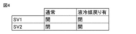
- FIG. 4 is a diagram showing a control state of the solenoid valve of the oil distribution unit in the first embodiment.
- the first valve SV1 is opened and the second valve SV2 is closed to give priority to the performance of the refrigeration cycle device 1.
- the first valve SV1 is closed and the second valve SV2 is opened.
- the lubricity of the compression device 10 is improved, and the high-temperature oil and the refrigerant return to the suction side of the compression device 10, so that the suction superheat degree increases, that is, the liquid refrigerant. It leads to the elimination of the return.
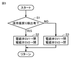
- FIG. 5 is a flowchart for explaining the control of the solenoid valve of the oil distribution unit executed by the control device in the first embodiment.
- the control device 100 determines whether or not the return of the liquid refrigerant has been detected.
- the return of the liquid refrigerant can be detected by observing the decrease in the degree of superheat (inhalation heating degree) of the refrigerant sucked by the compression device 10. Since the suction heating degree is also linked with the superheat degree (discharge heating degree) of the refrigerant discharged by the compression device 10, it may be detected by observing the decrease in the discharge superheating degree.
- step S1 the control device 100 determines that the liquid refrigerant has returned when the suction heating degree or the discharge superheat degree falls below a certain threshold value.
- the discharge superheat degree (T1-CT) of the temperature sensor 121 provided in the compressor discharge pipe is the same as the saturation temperature CT corresponding to the pressure PH detected by the pressure sensor 111 provided in the discharge pipe of the compressor 10. Obtained from the detection temperature T1. Further, the suction heating degree (T2-ET) is provided in the compressor suction pipe in the same manner as the saturation temperature ET corresponding to the detection pressure Pl of the pressure sensor 110 provided in the pipe 89 connected to the suction port G1 of the compressor 10. It is obtained from the detected temperature T2 of the obtained temperature sensor 122.
- control device 100 controls to open the first valve SV1 and close the second valve SV2 in step S3.
- control device 100 controls to close the first valve SV1 and open the second valve SV2 in step S2.
- oil distribution unit 150 may be configured to switch the flow path by providing something like a three-way valve instead of providing the first valve SV1 and the second valve SV2 as shown in FIG.
- Embodiment 2 In the case of a refrigerator used in a freezing warehouse or the like, as shown in FIG. 1, the load device 3 and the heat source unit 2 are connected by extension pipes 84 and 88 of the refrigerant. However, the load device 3 and the heat source unit 2 are not necessarily manufactured by the same manufacturer, and in many cases, they are not connected by a communication line or the like. Therefore, when the inside of the refrigerator is sufficiently cooled on the load device 3 side, the solenoid valve 70 is closed in the load device 3 to block the flow of the refrigerant in order to prevent it from becoming too cold.
- the control device 100 stops the operation of the compression device 10.
- Such an operation is also called a pump-down operation.
- the compression device 10 is stopped, the pressure PL is thus lower than usual, and the differential pressure between the suction port G1 and the discharge port G2 of the compression device 10 becomes large. Since each port of the compressor is internally shut off while the compressor is stopped, the differential pressure is maintained even when the compressor is stopped.
- the load device 3 opens the solenoid valve 70. Then, the pressure PL rises, and the control device 100 activates the compression device 10 accordingly.
- the startability of the compressor is improved by utilizing the oil return passage.
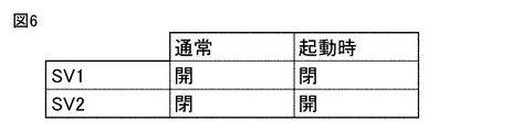
- FIG. 6 is a diagram showing a control state of the solenoid valve of the oil distribution unit in the second embodiment.
- the control device 100 opens the first valve SV1 and closes the second valve SV2 in order to improve the performance.
- the control device 100 closes the first valve SV1 and opens the second valve SV2.
- the refrigerant on the discharge side of the compression device 10 moves to the suction side, so that the pressure PH decreases and the pressure PL increases.
- the torque required to rotate the compression device 10 can also be small, so that the mobility of the compression device 10 is improved.
- the difference between the pressure PH and the pressure PL before startup is larger than the threshold value, the control at startup in FIG. 6 is performed.
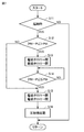
- FIG. 7 is a flowchart for explaining the control of the solenoid valve of the oil distribution unit executed by the control device in the second embodiment.
- the control device 100 closes the second valve SV2 at the same time when the compression device 10 is stopped.
- the control device 100 determines whether or not the compression device 10 is started. For example, when the power is turned on, when the pressure PL that was below the stop judgment threshold rises above the judgment threshold, or when the temperature inside the refrigerator rises above the threshold, control is performed. The device 100 determines that it is the time when the compression device 10 is started.
- step S12 the control device 100 determines whether or not the difference between the pressure PH and the pressure PL is larger than the threshold value Pth.
- step S13 the control device 100 closes the first valve SV1 and opens the second valve SV2.
- the refrigerant on the discharge side of the compression device 10 moves to the suction side, so that the pressure PH decreases and the pressure PL increases.
- step S14 the control device 100 determines whether or not the difference between the pressure PH and the pressure PL is equal to or less than the threshold value Pth. While the difference does not fall below the threshold value Pth, the process stays in step S14, and a time wait is performed.
- step S12 or step S14 If it is determined in step S12 or step S14 that the difference between the pressure PH and the pressure PL is equal to or less than the threshold value Pth (NO in S12 or YES in S14), the control device 100 is the first in step S15. The valve SV1 is opened and the second valve SV2 is closed. Then, in step S16, the control device 100 activates the compression device 10. The compression device 10 does not necessarily have to be started after the second valve SV2 is closed, and the compression device 10 may be started with the second valve SV2 open.
- Embodiment 3 an application example in which two compressors are connected in series and used is shown.
- two compressors When used under high compression ratio conditions such as a condition where the ratio of the high pressure side pressure to the low pressure side pressure is high, two compressors may be connected in series for use.
- Such a configuration is called a two-stage compression configuration.
- a two-stage compression configuration is adopted for a heat source unit when used in an ultra-low temperature state such as a fish freezer warehouse, a heat source unit using a CO 2 refrigerant, and the like.
- FIG. 8 is an overall configuration diagram of the refrigeration cycle device 201 of the third embodiment.
- the refrigeration cycle device 201 includes a heat source unit 202, a load device 3, and extension pipes 84 and 88.
- the heat source unit 202 is configured to be connected to the load device 3 by extension pipes 84 and 88. Since the load device 3 and the extension pipes 84 and 88 have the same configuration as that shown in FIG. 3, the description will not be repeated.
- the heat source unit 202 includes a compression device 10A instead of the compression device 10 in the configuration of the heat source unit 2 shown in FIG.
- the compressor 10A includes a first compressor 11 and a second compressor 12 and a pressure sensor 112 connected in series.
- the first compressor 11 sucks the refrigerant from the pipe 89 and discharges it to the second compressor 12.
- the second compressor 12 discharges the sucked refrigerant into the pipe 80.
- the pipe 93 which is an injection flow path, is connected to the connection portion between the first compressor 11 and the second compressor 12.
- the pressure sensor 112 detects the pressure PM of this connection portion.
- the first compressor 11 and the second compressor 12 have separate housings. Each housing contains a motor and a compression unit. A compressor having one housing and one motor may be used to perform two-stage compression. In this case, there are two discharge ports and two suction ports, one for low pressure and the other for high pressure.
- the first compressor 11 and the second compressor 12 are provided with oil amount sensors 131 and 132 for detecting the height of the oil level of the oil collected at the bottom of the housing, respectively. Then, the oil amount OL1 of the first compressor 11 is detected by the oil amount sensor 131, and the oil amount OL2 of the second compressor 12 is detected by the oil amount sensor 132.
- the second valve SV2 When the amount of oil in the first compressor 11 is small, the second valve SV2 is opened and the first valve SV1 is closed. On the other hand, when the amount of oil in the second compressor 12 is small, the bias in the amount of oil is suppressed by opening the first valve SV1 and closing the second valve SV2.
- FIG. 9 is a flowchart for explaining the control of the solenoid valve of the oil distribution unit executed by the control device in the third embodiment.
- the control device 100 determines whether or not the oil amount OL1 of the first compressor 11 is smaller than the determination threshold value Th1.
- the control device 100 closes the first valve SV1 and opens the second valve SV2 in step S22.
- the refrigerating machine oil is supplied from the oil separator to the suction port side of the first compressor 11, so that the oil amount OL1 increases.
- the control device 100 determines whether or not the oil amount OL2 of the second compressor 12 is smaller than the determination threshold Th2 in step S23. To judge.
- the control device 100 opens the first valve SV1 and closes the second valve SV2 in step S24.
- the refrigerating machine oil is supplied from the oil separator to the suction port side of the second compressor 12, so that the oil amount OL2 increases.
- the control device 100 does not perform the process of step S24, and the current state of the first valve SV1 and the second valve SV2. To maintain.
- step S24 since the amount of refrigerating machine oil filled is a certain amount, when the amount of oil OL1 is decreasing, the amount of oil OL2 is increasing. Therefore, if NO is determined in step S24 without performing the determination in step S23, the process of step S24 may be executed. On the contrary, the determination in step S23 may be performed without the determination in step S21, and if NO is determined in step S23, the processing in step S22 may be performed.
- Embodiment 4 In the fourth embodiment, another application example in which two compressors are connected in series and used will be described.
- an electronic expansion valve or a capillary tube is used in front of the second valve SV2
- both the first valve SV1 and the second valve SV2 are opened for operation, resulting in finer oil. It is possible to adjust the amount.
- FIG. 10 is an overall configuration diagram of the refrigeration cycle device 301 of the fourth embodiment.
- the refrigeration cycle device 301 shown in FIG. 10 includes a heat source unit 302, a load device 3, and extension pipes 84 and 88.
- the heat source unit 302 is configured to be connected to the load device 3 by extension pipes 84 and 88. Since the load device 3 and the extension pipes 84 and 88 have the same configuration as that shown in FIG. 3, the description will not be repeated.
- the heat source unit 302 includes an oil distribution unit 150A instead of the oil distribution unit 150 in the configuration of the heat source unit 202 shown in FIG. Since the other configurations of the heat source unit 302 are the same as the configurations of the heat source unit 202 shown in FIG. 8, the description will not be repeated.
- the oil distribution unit 150A further includes a flow rate adjusting valve LEV3 in addition to the configuration of the oil distribution unit 150.
- the flow rate adjusting valve LEV3 and the second valve SV2 are arranged in series with the pipe 95.
- the flow rate adjusting valve LEV3 is arranged on the upstream side of the second valve SV2, but these arrangements may be reversed. Further, if the flow rate adjusting valve LEV3 can be fully closed, the second valve SV2 may be omitted.
- An electronic expansion valve can be used as the flow rate adjusting valve LEV3.
- LEV3 By using the flow rate adjusting valve LEV3, it is possible to finely control the distribution ratio of oil to the first compressor 11 and the second compressor 12. For example, it is possible to return an equal amount of oil to the first compressor 11 and the second compressor 12.
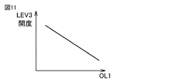
- FIG. 11 is a diagram showing a first example of a control state of the flow rate adjusting valve of the oil distribution unit according to the fourth embodiment.
- the first valve SV1 and the second valve SV2 are opened, and as shown in FIG. 11, when the oil amount OL1 of the first compressor 11 is large, the opening degree of the flow rate adjusting valve LEV3 is reduced.
- the opening degree of the flow rate adjusting valve LEV3 is increased.
- the amount of oil sealed in the refrigeration cycle device is constant, the amount of oil in the second compressor 12 is also adjusted to an appropriate amount by adjusting the amount of oil in the first compressor 11.
- FIG. 12 is a diagram showing a second example of the control state of the flow rate adjusting valve of the oil distribution unit according to the fourth embodiment.
- the opening degree of the flow rate adjusting valve LEV3 was changed according to the oil amount OL1 of the first compressor 11, but conversely, it was changed according to the oil amount OL2 of the second compressor 12.
- the opening degree of the flow rate adjusting valve LEV3 may be changed.
- the first valve SV1 and the second valve SV2 are opened, and as shown in FIG. 12, when the oil amount OL2 of the second compressor 12 is small, the opening degree of the flow rate adjusting valve LEV3 is reduced.
- the opening degree of the flow rate adjusting valve LEV3 is increased.
- the amount of oil sealed in the refrigeration cycle device is constant, the amount of oil in the first compressor 11 is also adjusted to an appropriate amount by adjusting the amount of oil in the second compressor 12.
- Embodiment 5 When the pipe length connecting the outdoor unit and the indoor unit is long, a large amount of oil may be filled in consideration of the pipe length. However, depending on the operating condition, the amount of oil may become excessive and the amount of oil accumulated in the compressor may increase. In that case, the accumulator may be used as an oil reservoir to store excess refrigerant.
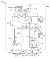
- FIG. 13 is an overall configuration diagram of the refrigeration cycle device 401 of the fifth embodiment.
- the refrigeration cycle device 401 shown in FIG. 13 includes a heat source unit 402, a load device 3, and extension pipes 84 and 88.
- the heat source unit 402 is configured to be connected to the load device 3 by extension pipes 84 and 88. Since the load device 3 and the extension pipes 84 and 88 have the same configuration as that shown in FIG. 3, the description will not be repeated.
- the heat source unit 402 further includes an accumulator 22, a pipe 96, a third valve SV3, and an oil amount sensor 130 in the configuration of the heat source unit 2 shown in FIG. Since the other configurations of the heat source unit 402 are the same as the configurations of the heat source unit 2 shown in FIG. 3, the description will not be repeated.
- a solenoid valve can be used as the third valve SV3.
- the accumulator 22 is arranged in the middle of the pipe 89.
- the oil amount sensor 130 detects the oil amount OL of the compression device 10.
- the oil distribution unit 150C includes pipes 94 to 96, a first valve SV1, a second valve SV2, and a third valve SV3.
- the pipe 94 connects between the oil outlet of the oil separator 20 and the pipe 93.
- the first valve SV1 is provided in the pipe 94 and opens and closes the flow path of the oil and the refrigerant.
- the second valve SV2 is provided in the pipe 95 and opens and closes the flow path of the oil and the refrigerant.
- the pipe 96 branches from the upstream portion of the first valve SV1 of the pipe 95 and joins the pipe 89 on the inlet side of the accumulator 22.
- the third valve SV3 is arranged in the middle of the pipe 96.
- a third valve SV3 is provided in addition to the second valve SV2, and the case where the oil is returned directly to the compression device 10 and the case where the oil is stored in the accumulator 22 are switched.
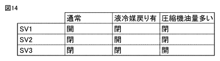
- FIG. 14 is a diagram showing a control state of the solenoid valve of the oil distribution unit in the fifth embodiment.
- the first valve SV1 is opened, and the second valve SV2 and the third valve SV3 are closed in order to give priority to performance.
- the compressor may be insufficiently lubricated, so the second valve SV2 is opened, and the first valve SV1 and the third valve SV3 are closed.
- the third valve SV3 is opened, and the first valve SV1 and the second valve SV2 are closed. And store the oil in the accumulator.
- FIG. 15 is a flowchart for explaining the control of the solenoid valve of the oil distribution unit executed by the control device in the fifth embodiment.
- the control device 100 determines whether or not the return of the liquid refrigerant has been detected.
- the return of the liquid refrigerant can be detected by observing a decrease in the superheat degree (suction heat degree) of the refrigerant sucked by the compression device 10 or a decrease in the discharge superheat degree, as in the first embodiment.
- control device 100 opens the second valve SV2 and closes the first valve SV1 and the third valve SV3 in step S32.
- step S33 the control device 100 determines whether the oil amount OL of the compression device 10 is larger than the determination threshold value Th. To judge.
- the control device 100 opens the third valve SV3 in step S34 and closes the first valve SV1 and the second valve SV2.
- the refrigerating machine oil is supplied from the oil separator 20 supplied to the suction port of the compression device 10 to the inlet side of the accumulator 22, so that the amount of oil OL is reduced.
- the control device 100 opens the first valve SV1 and closes the second valve SV2 and the third valve SV3 in step S35. ..
- FIG. 16 is an overall configuration diagram of the refrigeration cycle device 501 of the modified example of the fifth embodiment.
- the refrigeration cycle device 501 includes a heat source unit 502, a load device 3, and extension pipes 84 and 88.
- the heat source unit 502 is configured to be connected to the load device 3 by extension pipes 84 and 88. Since the load device 3 and the extension pipes 84 and 88 have the same configuration as that shown in FIG. 3, the description will not be repeated.
- the heat source unit 502 includes a compression device 10A instead of the compression device 10 in the configuration of the heat source unit 402 shown in FIG.
- the other configuration of the heat source unit 502 is the same as the configuration of the heat source unit 402 shown in FIG. 13, and the compression device 10A has the same configuration as that of FIG.
- the control device 100 opens the second valve SV2 and closes the first valve SV1 and the third valve SV3.
- the first valve SV1 is opened, and the second valve SV2 and the third valve SV3 are closed.
- the third valve SV3 is opened, and the first valve SV1 and the second valve SV2 are closed.
- the accumulator 22 may also be provided with an oil amount sensor, and the oil amount of the accumulator may be added as a control parameter. Since the amount of refrigerating machine oil sealed in the refrigerating cycle device 501 is constant, if at least two oil amounts of the first compressor 11, the second compressor 12, and the accumulator 22 are detected, the same control can be performed. It is possible.
- the suction superheat degree or the discharge superheat degree of the compressor is also detected by using the temperature sensor and the pressure sensor. Then, the oil amount may be determined in combination with the output of the oil amount sensor.
- the present disclosure relates to a heat source unit 2 of a refrigeration cycle device 1 configured to be connected to a load device 3 including a first expansion device LEV1 and an evaporator 60.
- the heat source unit 2 is arranged in the first flow path (80 to 83, 89), which forms a circulation flow path through which the refrigerant circulates by being connected to the load device 3, and the suction port G1 and the suction port G1.
- the compressor 10 is configured to suck the refrigerant from the intermediate pressure port G3 and discharge the refrigerant from the discharge port G2, and is arranged downstream of the compressor 10 of the first flow path to provide the refrigerant inlet, the refrigerant outlet and the oil outlet.
- a second flow path (91, 93) configured to return the refrigerant that has passed through the condenser 30 from the intermediate pressure port G3 to the compression device 10, and a second expansion device LEV2 arranged in the second flow path.
- It includes an oil distribution unit 150 configured to return the refrigerating machine oil discharged from the oil outlet of the oil separator 20 to the compressor 10 via the intermediate pressure port G3 and the suction port G1.
- the oil distribution unit 150 is configured so that the ratio of the refrigerating machine oil distributed to the intermediate pressure port G3 and the suction port G1 can be changed.
- the oil distribution unit 150 includes a first valve SV1 that communicates the oil outlet of the oil separator 20 and the intermediate pressure port G3, and a second valve SV2 that communicates the oil outlet of the oil separator 20 and the suction port G1. including.
- the heat source unit 2 further includes a control device 100 that controls the first valve SV1 and the second valve SV2. As shown in FIGS. 4 and 5, when the amount of liquid refrigerant returned to the suction port G1 increases from the determination value, the control device 100 opens the second valve SV2 and closes the first valve SV1.
- the heat source unit 2 further includes a control device 100 that controls the first valve SV1 and the second valve SV2. As shown in FIGS. 6 and 7, when the compression device 10 is activated and the pressure difference
- the compressor 10A sucks the refrigerant from the suction port and discharges the refrigerant to the pipe connected to the intermediate pressure port, and sucks the refrigerant from the pipe connected to the intermediate pressure port.
- a second compressor 12 that discharges to the discharge port.
- the oil distribution unit 150A has a flow rate for communicating the oil outlet of the oil separator 20 and the intermediate pressure port with the first valve SV1 and the oil outlet of the oil separator 20 with the suction port. Includes a regulating valve LEV3.
- the heat source unit 402 further includes an accumulator 22 arranged upstream of the compression device 10 in the first flow path.
- the oil distribution unit 150C includes a first valve SV1 that communicates the oil outlet of the oil separator 20 and the intermediate pressure port G3, and a second valve SV2 that communicates the oil outlet of the oil separator 20 and the suction port G1. , A third valve SV3 that communicates the oil outlet of the oil separator 20 with the inlet of the accumulator 22.
- the present disclosure relates, in other aspects, to refrigeration cycle devices 1,201,301,401,501 comprising any of the above heat source units 2,202, 302, 402, 502 and a load device 3.
- the present disclosure relates to a refrigerator provided with the refrigeration cycle apparatus 1,201,301,401,501 in another aspect.
- Refrigeration cycle device 1,201,301,401,501 Refrigeration cycle device, 2,202,302,402,502 Heat source unit, 3 Load device, 10,10A compressor, 11 First compressor, 12 Second compressor, 20 Oil separation Vessel, 22 accumulator, 30 condenser, 40 receiver, 60 evaporator, 70 electromagnetic valve, 80-83, 85-87, 89, 91, 93-96 piping, 84, 88 extension piping, 100 control device, 104 Memory, 110-112 pressure sensor, 121,122 temperature sensor, 130-132 oil amount sensor, 150, 150A, 150C oil distribution unit, G1 suction port, G2 discharge port, G3 intermediate pressure port, LEV1 first expansion device, LEV2 Second expansion device, LEV3 flow control valve, SV1 first valve, SV2 second valve, SV3 third valve.
Landscapes
- Engineering & Computer Science (AREA)
- Physics & Mathematics (AREA)
- Mechanical Engineering (AREA)
- Thermal Sciences (AREA)
- General Engineering & Computer Science (AREA)
- Chemical & Material Sciences (AREA)
- Analytical Chemistry (AREA)
- Power Engineering (AREA)
- Applications Or Details Of Rotary Compressors (AREA)
- Compression-Type Refrigeration Machines With Reversible Cycles (AREA)
Priority Applications (3)
| Application Number | Priority Date | Filing Date | Title |
|---|---|---|---|
| EP20931630.6A EP4137756A4 (en) | 2020-04-14 | 2020-04-14 | HEAT SOURCE UNIT, REFRIGERATION CYCLE DEVICE AND REFRIGERATOR |
| PCT/JP2020/016420 WO2021210064A1 (ja) | 2020-04-14 | 2020-04-14 | 熱源ユニット、冷凍サイクル装置および冷凍機 |
| JP2022514898A JP7330367B2 (ja) | 2020-04-14 | 2020-04-14 | 熱源ユニット、冷凍サイクル装置および冷凍機 |
Applications Claiming Priority (1)
| Application Number | Priority Date | Filing Date | Title |
|---|---|---|---|
| PCT/JP2020/016420 WO2021210064A1 (ja) | 2020-04-14 | 2020-04-14 | 熱源ユニット、冷凍サイクル装置および冷凍機 |
Publications (1)
| Publication Number | Publication Date |
|---|---|
| WO2021210064A1 true WO2021210064A1 (ja) | 2021-10-21 |
Family
ID=78083843
Family Applications (1)
| Application Number | Title | Priority Date | Filing Date |
|---|---|---|---|
| PCT/JP2020/016420 Ceased WO2021210064A1 (ja) | 2020-04-14 | 2020-04-14 | 熱源ユニット、冷凍サイクル装置および冷凍機 |
Country Status (3)
| Country | Link |
|---|---|
| EP (1) | EP4137756A4 (https=) |
| JP (1) | JP7330367B2 (https=) |
| WO (1) | WO2021210064A1 (https=) |
Cited By (7)
| Publication number | Priority date | Publication date | Assignee | Title |
|---|---|---|---|---|
| JP2023161663A (ja) * | 2022-04-26 | 2023-11-08 | シーピーエンジニアリング株式会社 | 冷菓製造装置 |
| WO2024014027A1 (ja) * | 2022-07-14 | 2024-01-18 | 三菱重工業株式会社 | 冷凍システム |
| WO2024023988A1 (ja) * | 2022-07-27 | 2024-02-01 | 三菱電機株式会社 | 冷凍サイクル装置 |
| WO2024071213A1 (ja) * | 2022-09-30 | 2024-04-04 | ダイキン工業株式会社 | 冷凍サイクル装置 |
| WO2024106478A1 (ja) * | 2022-11-17 | 2024-05-23 | パナソニックIpマネジメント株式会社 | 冷凍システム及びアキュムレータ |
| WO2025243497A1 (ja) * | 2024-05-24 | 2025-11-27 | 三菱電機株式会社 | 冷凍サイクル装置 |
| EP4682440A1 (de) * | 2024-07-18 | 2026-01-21 | Weiss Technik GmbH | Prüfkammer und verfahren zur steuerung |
Families Citing this family (1)
| Publication number | Priority date | Publication date | Assignee | Title |
|---|---|---|---|---|
| CN115854594B (zh) * | 2022-12-26 | 2025-04-22 | 珠海格力电器股份有限公司 | 均油控制方法、装置和空调机组 |
Citations (8)
| Publication number | Priority date | Publication date | Assignee | Title |
|---|---|---|---|---|
| JPH0452466A (ja) * | 1990-06-18 | 1992-02-20 | Daikin Ind Ltd | 冷凍装置及び冷凍装置の運転制御装置 |
| JPH06229634A (ja) * | 1993-02-01 | 1994-08-19 | Sanyo Electric Co Ltd | 冷凍装置 |
| JP2001289519A (ja) * | 2000-04-06 | 2001-10-19 | Mitsubishi Electric Corp | 冷凍装置 |
| JP2012247134A (ja) * | 2011-05-27 | 2012-12-13 | Sanyo Electric Co Ltd | 超低温冷凍装置 |
| WO2016079859A1 (ja) * | 2014-11-20 | 2016-05-26 | 三菱電機株式会社 | 冷凍サイクル装置 |
| JP2017116136A (ja) * | 2015-12-22 | 2017-06-29 | パナソニックIpマネジメント株式会社 | 空気調和装置 |
| WO2019021360A1 (ja) * | 2017-07-25 | 2019-01-31 | 三菱電機株式会社 | 冷凍サイクル装置 |
| WO2019026270A1 (ja) | 2017-08-04 | 2019-02-07 | 三菱電機株式会社 | 冷凍サイクル装置および熱源ユニット |
Family Cites Families (3)
| Publication number | Priority date | Publication date | Assignee | Title |
|---|---|---|---|---|
| CN106052178A (zh) * | 2016-05-29 | 2016-10-26 | 湖南大学 | 一种带经济器和油冷却压缩两级制冷循环系统 |
| CN109140829B (zh) * | 2018-08-13 | 2019-11-19 | 珠海格力电器股份有限公司 | 压缩机回油结构、制冷机组及空调系统 |
| CN110966202A (zh) * | 2018-09-30 | 2020-04-07 | 广东美芝精密制造有限公司 | 压缩机组件、压缩机组件的控制方法和制冷设备 |
-
2020
- 2020-04-14 JP JP2022514898A patent/JP7330367B2/ja active Active
- 2020-04-14 WO PCT/JP2020/016420 patent/WO2021210064A1/ja not_active Ceased
- 2020-04-14 EP EP20931630.6A patent/EP4137756A4/en active Pending
Patent Citations (8)
| Publication number | Priority date | Publication date | Assignee | Title |
|---|---|---|---|---|
| JPH0452466A (ja) * | 1990-06-18 | 1992-02-20 | Daikin Ind Ltd | 冷凍装置及び冷凍装置の運転制御装置 |
| JPH06229634A (ja) * | 1993-02-01 | 1994-08-19 | Sanyo Electric Co Ltd | 冷凍装置 |
| JP2001289519A (ja) * | 2000-04-06 | 2001-10-19 | Mitsubishi Electric Corp | 冷凍装置 |
| JP2012247134A (ja) * | 2011-05-27 | 2012-12-13 | Sanyo Electric Co Ltd | 超低温冷凍装置 |
| WO2016079859A1 (ja) * | 2014-11-20 | 2016-05-26 | 三菱電機株式会社 | 冷凍サイクル装置 |
| JP2017116136A (ja) * | 2015-12-22 | 2017-06-29 | パナソニックIpマネジメント株式会社 | 空気調和装置 |
| WO2019021360A1 (ja) * | 2017-07-25 | 2019-01-31 | 三菱電機株式会社 | 冷凍サイクル装置 |
| WO2019026270A1 (ja) | 2017-08-04 | 2019-02-07 | 三菱電機株式会社 | 冷凍サイクル装置および熱源ユニット |
Non-Patent Citations (1)
| Title |
|---|
| See also references of EP4137756A4 |
Cited By (13)
| Publication number | Priority date | Publication date | Assignee | Title |
|---|---|---|---|---|
| JP7769377B2 (ja) | 2022-04-26 | 2025-11-13 | シーピーエンジニアリング株式会社 | 冷菓製造装置 |
| JP2023161663A (ja) * | 2022-04-26 | 2023-11-08 | シーピーエンジニアリング株式会社 | 冷菓製造装置 |
| WO2024014027A1 (ja) * | 2022-07-14 | 2024-01-18 | 三菱重工業株式会社 | 冷凍システム |
| JP2024011228A (ja) * | 2022-07-14 | 2024-01-25 | 三菱重工業株式会社 | 冷凍システム |
| JP7801967B2 (ja) | 2022-07-14 | 2026-01-19 | 三菱重工業株式会社 | 冷凍システム |
| WO2024023988A1 (ja) * | 2022-07-27 | 2024-02-01 | 三菱電機株式会社 | 冷凍サイクル装置 |
| GB2634430A (en) * | 2022-07-27 | 2025-04-09 | Mitsubishi Electric Corp | Refrigeration cycle device |
| JP7578883B2 (ja) | 2022-09-30 | 2024-11-07 | ダイキン工業株式会社 | 冷凍サイクル装置 |
| JP2024052348A (ja) * | 2022-09-30 | 2024-04-11 | ダイキン工業株式会社 | 冷凍サイクル装置 |
| WO2024071213A1 (ja) * | 2022-09-30 | 2024-04-04 | ダイキン工業株式会社 | 冷凍サイクル装置 |
| WO2024106478A1 (ja) * | 2022-11-17 | 2024-05-23 | パナソニックIpマネジメント株式会社 | 冷凍システム及びアキュムレータ |
| WO2025243497A1 (ja) * | 2024-05-24 | 2025-11-27 | 三菱電機株式会社 | 冷凍サイクル装置 |
| EP4682440A1 (de) * | 2024-07-18 | 2026-01-21 | Weiss Technik GmbH | Prüfkammer und verfahren zur steuerung |
Also Published As
| Publication number | Publication date |
|---|---|
| EP4137756A4 (en) | 2023-08-16 |
| JPWO2021210064A1 (https=) | 2021-10-21 |
| JP7330367B2 (ja) | 2023-08-21 |
| EP4137756A1 (en) | 2023-02-22 |
Similar Documents
| Publication | Publication Date | Title |
|---|---|---|
| JP7330367B2 (ja) | 熱源ユニット、冷凍サイクル装置および冷凍機 | |
| US11892216B2 (en) | Refrigeration system with direct expansion refrigeration mode and refrigerant pumping energy-efficiency mode and control method of refrigeration system | |
| WO2010013392A1 (ja) | 冷凍装置 | |
| US9651288B2 (en) | Refrigeration apparatus and refrigeration cycle apparatus | |
| CN104613699B (zh) | 冰箱 | |
| EP3954947B1 (en) | Outdoor unit, refrigeration cycle device, and refrigerating machine | |
| CN106382701A (zh) | 多联机空调及其室外机、控制方法和装置 | |
| JP2009150628A (ja) | 空気調和装置に用いられる高圧シェル圧縮機の均油システム | |
| JP7387022B2 (ja) | 冷熱源ユニットおよび冷凍サイクル装置 | |
| CN104613698A (zh) | 冰箱及其控制方法 | |
| JP7378561B2 (ja) | 室外ユニットおよび冷凍サイクル装置 | |
| JP7224480B2 (ja) | 室外ユニットおよび冷凍サイクル装置 | |
| JP6080031B2 (ja) | 冷凍装置 | |
| JP2013155972A (ja) | 冷凍装置 | |
| JP2010002173A (ja) | 冷凍装置 | |
| JP2013024538A (ja) | 冷凍装置 | |
| WO2021177429A1 (en) | Heat pump system and method for controlling the same | |
| CN114364929B (zh) | 室外单元以及冷冻循环装置 | |
| US20090077985A1 (en) | Refrigerating Apparatus | |
| JP7412639B2 (ja) | 熱源ユニット | |
| JP2010054192A (ja) | 冷凍装置 | |
| CN115427744A (zh) | 空调装置 | |
| JP2019128112A (ja) | 冷凍装置 | |
| US12474094B2 (en) | Refrigeration apparatus with oil return control mechanism for compressors | |
| CN115371308A (zh) | 一种防回液空调系统及控制方法 |
Legal Events
| Date | Code | Title | Description |
|---|---|---|---|
| 121 | Ep: the epo has been informed by wipo that ep was designated in this application |
Ref document number: 20931630 Country of ref document: EP Kind code of ref document: A1 |
|
| ENP | Entry into the national phase |
Ref document number: 2022514898 Country of ref document: JP Kind code of ref document: A |
|
| NENP | Non-entry into the national phase |
Ref country code: DE |
|
| ENP | Entry into the national phase |
Ref document number: 2020931630 Country of ref document: EP Effective date: 20221114 |