WO2021206139A1 - 工具 - Google Patents
工具 Download PDFInfo
- Publication number
- WO2021206139A1 WO2021206139A1 PCT/JP2021/014892 JP2021014892W WO2021206139A1 WO 2021206139 A1 WO2021206139 A1 WO 2021206139A1 JP 2021014892 W JP2021014892 W JP 2021014892W WO 2021206139 A1 WO2021206139 A1 WO 2021206139A1
- Authority
- WO
- WIPO (PCT)
- Prior art keywords
- intermediate member
- tool
- sensor
- mounting
- accessory
- Prior art date
- Legal status (The legal status is an assumption and is not a legal conclusion. Google has not performed a legal analysis and makes no representation as to the accuracy of the status listed.)
- Ceased
Links
Images


Classifications
-
- B—PERFORMING OPERATIONS; TRANSPORTING
- B25—HAND TOOLS; PORTABLE POWER-DRIVEN TOOLS; MANIPULATORS
- B25F—COMBINATION OR MULTI-PURPOSE TOOLS NOT OTHERWISE PROVIDED FOR; DETAILS OR COMPONENTS OF PORTABLE POWER-DRIVEN TOOLS NOT PARTICULARLY RELATED TO THE OPERATIONS PERFORMED AND NOT OTHERWISE PROVIDED FOR
- B25F5/00—Details or components of portable power-driven tools not particularly related to the operations performed and not otherwise provided for
-
- B—PERFORMING OPERATIONS; TRANSPORTING
- B24—GRINDING; POLISHING
- B24B—MACHINES, DEVICES, OR PROCESSES FOR GRINDING OR POLISHING; DRESSING OR CONDITIONING OF ABRADING SURFACES; FEEDING OF GRINDING, POLISHING, OR LAPPING AGENTS
- B24B49/00—Measuring or gauging equipment for controlling the feed movement of the grinding tool or work; Arrangements of indicating or measuring equipment, e.g. for indicating the start of the grinding operation
- B24B49/12—Measuring or gauging equipment for controlling the feed movement of the grinding tool or work; Arrangements of indicating or measuring equipment, e.g. for indicating the start of the grinding operation involving optical means
-
- B—PERFORMING OPERATIONS; TRANSPORTING
- B24—GRINDING; POLISHING
- B24B—MACHINES, DEVICES, OR PROCESSES FOR GRINDING OR POLISHING; DRESSING OR CONDITIONING OF ABRADING SURFACES; FEEDING OF GRINDING, POLISHING, OR LAPPING AGENTS
- B24B23/00—Portable grinding machines, e.g. hand-guided; Accessories therefor
- B24B23/005—Auxiliary devices used in connection with portable grinding machines, e.g. holders
-
- B—PERFORMING OPERATIONS; TRANSPORTING
- B24—GRINDING; POLISHING
- B24B—MACHINES, DEVICES, OR PROCESSES FOR GRINDING OR POLISHING; DRESSING OR CONDITIONING OF ABRADING SURFACES; FEEDING OF GRINDING, POLISHING, OR LAPPING AGENTS
- B24B23/00—Portable grinding machines, e.g. hand-guided; Accessories therefor
- B24B23/02—Portable grinding machines, e.g. hand-guided; Accessories therefor with rotating grinding tools; Accessories therefor
- B24B23/028—Angle tools
-
- B—PERFORMING OPERATIONS; TRANSPORTING
- B24—GRINDING; POLISHING
- B24B—MACHINES, DEVICES, OR PROCESSES FOR GRINDING OR POLISHING; DRESSING OR CONDITIONING OF ABRADING SURFACES; FEEDING OF GRINDING, POLISHING, OR LAPPING AGENTS
- B24B55/00—Safety devices for grinding or polishing machines; Accessories fitted to grinding or polishing machines for keeping tools or parts of the machine in good working condition
- B24B55/04—Protective covers for the grinding wheel
- B24B55/05—Protective covers for the grinding wheel specially designed for portable grinding machines
- B24B55/052—Protective covers for the grinding wheel specially designed for portable grinding machines with rotating tools
-
- B—PERFORMING OPERATIONS; TRANSPORTING
- B25—HAND TOOLS; PORTABLE POWER-DRIVEN TOOLS; MANIPULATORS
- B25F—COMBINATION OR MULTI-PURPOSE TOOLS NOT OTHERWISE PROVIDED FOR; DETAILS OR COMPONENTS OF PORTABLE POWER-DRIVEN TOOLS NOT PARTICULARLY RELATED TO THE OPERATIONS PERFORMED AND NOT OTHERWISE PROVIDED FOR
- B25F5/00—Details or components of portable power-driven tools not particularly related to the operations performed and not otherwise provided for
- B25F5/02—Construction of casings, bodies or handles
Definitions
- the present invention relates to a tool configured so that two types of accessories can be attached and detached.
- a cover also called a wheel cover, disc cover, blade case, etc.
- a side handle for gripping with the other hand when gripping the handle and a detachable accessory are provided.
- Patent Document 1 discloses a grinder including a sensor that detects whether or not a cover is attached, and a controller that prohibits rotation of a tip tool when the cover is not attached.
- Patent Document 2 discloses a grinder including a sensor for detecting whether or not a cover is attached and a sensor for detecting whether or not a side handle is attached.
- This specification discloses tools.
- This tool has a first attachment part, a second accessory, a first attachment part configured so that the first accessory can be attached and detached, and a second accessory can be attached and detached.
- the second mounting portion configured to be mounted and the first accessory to the first mounting portion, it is configured to be displaced from the first non-mounting position to the first mounting position.
- a second intermediate member configured to be displaced from a second non-mounting position to a second mounting position by attaching the first intermediate member and the second accessory to the second mounting portion.
- one sensor configured to detect a specific state in which the first intermediate member is in the first mounting position and the second intermediate member is in the second mounting position. May be good.
- one sensor detects that the first intermediate member is in the first mounting position and the second intermediate member is in the second mounting position.
- the fact that the first intermediate member is in the first mounting position means that the first accessory is mounted, and that the second intermediate member is in the second mounting position is that the second intermediate member is in the second mounting position. Since it means that accessories are attached, it is possible to detect that two types of accessories are attached with one sensor.
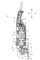
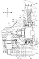
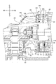
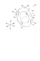
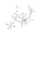
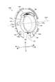
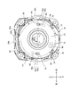
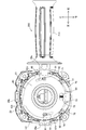
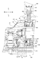
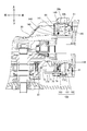
- FIG. 1st Embodiment of this invention It is a vertical cross-sectional view of the grinding machine according to 1st Embodiment of this invention, and shows the state which the side grip and the wheel cover are attached. It is a vertical sectional view of a grinding machine, and shows a state in which the side grip and the wheel cover are removed. It is a partially enlarged view of the grinder shown in FIG. It is a partially enlarged view of the grinder shown in FIG. It is a perspective view of the 1st intermediate member. It is a perspective view of the 2nd intermediate member. It is a perspective view of the holding member which holds a 1st intermediate member and a 2nd intermediate member. It is a perspective view of the sensor fixing member.
- the tool comprises a first accessory, a second accessory, and a first attachment configured such that the first accessory is detachably attached.
- the second attachment portion configured so that the second accessory can be detachably attached and the first accessory to the first attachment portion
- the first attachment from the first non-attachment position can be achieved.
- the first intermediate member configured to be displaced to the position and the second accessory to the second attachment portion
- the second intermediate member is displaced from the second non-attachment position to the second attachment position.
- the second intermediate member and the first intermediate member are in the first mounting position, and the second intermediate member is configured to detect a specific state in the second mounting position. It may be provided with one sensor.
- one sensor detects that the first intermediate member is in the first mounting position and the second intermediate member is in the second mounting position.
- the fact that the first intermediate member is in the first mounting position means that the first accessory is mounted, and that the second intermediate member is in the second mounting position is that the second intermediate member is in the second mounting position. Since it means that accessories are attached, it is possible to detect that two types of accessories are attached with one sensor.
- one sensor may be a photoelectric sensor having a light emitting part and a light receiving part, or an ultrasonic sensor.
- the first intermediate member connects the position where the light emitted from the light emitting portion or the ultrasonic wave transmitted from the ultrasonic sensor is blocked and the position where the light or the ultrasonic wave is not blocked to the first mounting portion. It may be configured to be displaced due to the presence or absence of attachment of a first accessory.
- the second intermediate member is displaced between a position that blocks light or ultrasonic waves and a position that does not block light or ultrasonic waves due to the presence or absence of a second accessory attached to the second attachment portion. It may be configured to be. According to this configuration, it is possible to easily detect that two types of accessories are attached by using one photoelectric sensor or one ultrasonic sensor.
- one sensor may be a reflective photo sensor. In one or more embodiments, one sensor may be a transmissive photosensor.
- the tool may include an electric motor and a controller configured to control the drive of the electric motor.
- the controller may allow the electric motor to be driven when one sensor detects a specific state, and may prohibit the electric motor from being driven when one sensor does not detect the specific state.
- the tool may be a grinder with a tip tool configured to be rotated by an electric motor.
- the first accessory may be a side grip and the second accessory may be a cover that partially covers the tip tool.
- the first attachment may include at least two side grip attachments for selectively attaching the side grips.
- the first intermediate member may be a single member that is provided in common to at least two side grip mounting portions and is rotatably configured around the rotation axis of the electric motor. At least two side grip mounting portions may be located at positions separated from each other in the circumferential direction of the rotation axis.
- the first intermediate member is at least directly or indirectly pressed against the side grip when the side grip is attached to one side grip attachment that is arbitrarily selected from at least two side grip attachments. It may have one pressed portion and rotate about the rotation axis when at least one pressed portion is pressed. According to this configuration, it is possible to detect when the side grip is attached to any of at least two side grip attachment portions. Moreover, since a single first intermediate member is shared with at least two side grip mounting portions, the number of parts can be reduced.
- the first intermediate member may have the shape of a ring or a partial ring. According to this configuration, the first intermediate member has a shape corresponding to the arrangement of at least two side grip mounting portions, so that it is a simple configuration and is single for at least two side grip mounting portions. The first intermediate member can be shared.
- the at least one pressed portion may project radially outward from the first intermediate member body and corresponds to the position of at least two side grip attachment portions, respectively. It may be provided at at least two positions respectively. According to this configuration, the first intermediate member can be easily rotated.
- At least one pressed portion displaces the first intermediate member in a direction different from the longitudinal direction of the side grip when the side grip is attached to one side grip attachment portion.
- a pressed surface angled with respect to the longitudinal direction of the side grip may be provided. According to this configuration, the first intermediate member can be easily rotated.
- the first intermediate member body may have a first through hole having an arc shape centered on the axis of rotation.
- the first intermediate member body may be screwed through the first through hole so as to be rotatable along the arc shape. According to this configuration, the first intermediate member can be rotatably held by a simple configuration.
- the first intermediate member may have a second through hole.
- Light or ultrasonic waves may pass through the second through hole when the first intermediate member is in a position that does not block the light or ultrasonic waves. According to this configuration, the size of the first intermediate member can be made compact.
- the second intermediate member is configured to be directly or indirectly pressed against the cover to move linearly when the cover is attached to the second attachment. May be good. According to this configuration, if the mounting direction of the cover is the linear motion direction of the second intermediate member, the direction changing mechanism becomes unnecessary, so that the second intermediate member can be displaced with a simple configuration.
- the second intermediate member may have a third through hole in the form of an elongated hole whose longitudinal direction is the direction in which the second intermediate member moves linearly.
- the second intermediate member may be screwed through the third through hole so as to be able to move linearly along the elongated hole. According to this configuration, the second intermediate member can be held in a linear motion with a simple configuration.
- the tool may include a single holding member that holds the first intermediate member and the second intermediate member. According to this configuration, if each of the first intermediate member and the second intermediate member is attached to the holding member, the relative positions of the first intermediate member and the second intermediate member are naturally determined. That is, it is not necessary to adjust the relative positions of the first intermediate member and the second intermediate member when assembling the tool.
- a hand-held electric disc grinding machine (hereinafter, simply referred to as a grinding machine) 10 will be illustrated as a tool.
- the grinder 10 is configured to rotationally drive a substantially disk-shaped tip tool 28 mounted on the spindle 25.
- the spindle 25 is rotated by a rotational driving force provided by an electric motor 31 as a prime mover.
- a grindstone, a rubber pad, a brush, a blade, and the like are prepared.
- the user selects an appropriate tip tool 28 according to the desired machining operation and attaches it to the grinder 10.
- processing operations such as grinding, polishing, and cutting can be performed on the work material according to the type of the tip tool 28.
- the direction in which the rotation axis AX1 (in other words, the motor shaft 32) of the electric motor 31 extends is defined as the front-rear direction of the grinder 10.
- the side where the tip tool 28 is located is defined as the front side
- the opposite side is defined as the rear side.
- the direction in which the rotation axis AX2 of the spindle 25 (in other words, the rotation axis of the tip tool 28) extends is defined as the vertical direction of the grinder 10.
- the side where the tip tool 28 is located is defined as the lower side
- the opposite side is defined as the upper side.
- the directions orthogonal to the vertical direction and the front-back direction are defined as the horizontal direction of the grinder 10.
- the right side when the front side is viewed from the rear side is defined as the right side of the grinder 10
- the opposite side is defined as the left side of the grinder 10.
- the grinder 10 includes a gear housing 20, a motor housing 30, and a handle housing 40.
- the electric motor 31 is housed in the motor housing 30 located between the gear housing 20 and the handle housing 40 in the front-rear direction, that is, in the longitudinal direction of the grinder 10.
- the electric motor 31 is configured to be driven by power supplied from the outside (AC power supplied from an AC power source in the present embodiment, but may be DC power supplied from a battery). ..
- a controller 33 is housed between the electric motor 31 and the switch 41 in the front-rear direction.
- the controller 33 receives the electric power supplied from the outside and supplies the electric power to the electric motor 31 and the sensor 80 described later.
- the controller 33 controls the drive of the electric motor 31 by controlling the electric power supplied to the electric motor 31.
- a mechanism for transmitting the rotational driving force of the electric motor 31 to the tip tool 28 is housed in the gear housing 20.
- the small bevel gear 23, the large bevel gear 24, and the spindle 25 are housed in the gear housing 20.
- the small bevel gear 23 is fixed around the motor shaft 32 at the front end of the motor shaft 32 of the electric motor 31.
- the spindle 25 is rotatably supported around the rotation axis AX2 by bearings arranged apart from each other in the vertical direction.
- the rotation axis AX2 intersects (more specifically, orthogonally) with the rotation axis AX1 of the electric motor 31.
- the large bevel gear 24 is fixed around the spindle 25 on the upper side of the spindle 25 and meshes with the small bevel gear 23.
- the gear housing 20 has a second mounting portion 22 at the lower end thereof for detachably mounting the cover 300.
- the second mounting portion 22 has a cylindrical shape extending in the vertical direction.
- the spindle 25 extends in the gear housing 20 in the vertical direction, and extends downward from the gear housing 20 (more specifically, the second mounting portion 22).
- an inner flange 26 is attached around the spindle 25.
- a male threaded portion is formed below the inner flange 26 of the spindle 25, and a locknut 27 is attached to the male threaded portion.
- the position of the tip tool 28 with respect to the spindle 25 is fixed by sandwiching the tip tool 28 between the inner flange 26 and the locknut 27 and tightening the locknut 27.
- the handle housing 40 is a part for the user to grip with one hand when using the grinder 10.
- the handle housing 40 has a cylindrical shape that extends substantially in the front-rear direction.
- a switch 41 for driving the electric motor 31 is housed inside the handle housing 40.
- An operating member 50 configured to be displaceable between an off position for turning off the switch 41 and an on position for turning on the switch 41 is provided on the lower side of the handle housing 40. In FIGS. 1 and 2, the operating member 50 in the off position is shown.
- a lock-off switch 57 is provided near the front end of the operating member 50 in the front-rear direction to lock the operating member 50 to the off position and prevent displacement to the on position.
- the switch 41 detects it and sends a detection signal to the controller 33.
- the controller 33 supplies electric power to the electric motor 31 to drive the electric motor 31.
- the rotation of the motor shaft 32 is transmitted to the spindle 25 while being decelerated via the small bevel gear 23 and the large bevel gear 24.
- the direction of the rotational movement is also changed from the direction around the motor shaft 32 to the direction around the rotation axis AX2 of the spindle 25.
- the grinder 10 further includes a side handle 200 and a cover 300 as its accessories.
- the side handle 200 is provided for the user to grip the handle housing 40 with a hand opposite to the hand that grips the handle housing 40. By using the side handle 200, the user can hold the grinder 10 more stably.
- the side handle 200 includes a grip portion 210 for the user to grip and a mounting portion 220 for mounting on the gear housing 20.
- the mounting portion 220 has a cylindrical shape extending in the longitudinal direction of the side handle 200, and extends from one end of the grip portion 210 in the longitudinal direction of the side handle 200.
- a male screw is formed on the outer peripheral surface of the mounting portion 220.
- the gear housing 20 has three first mounting portions 29a to 29c for detachably mounting the side handle 200.
- the first mounting portions 29a to 29c are arranged at positions separated from each other in the circumferential direction around the rotation axis AX1. More specifically, the first mounting portion 29a is formed on the left side surface of the gear housing 20, the first mounting portion 29b is formed on the upper surface of the gear housing 20, and the first mounting portion 29c is the gear. It is formed on the right side surface of the housing 20.
- the three first mounting portions 29a to 29c are provided at positions symmetrical with respect to the rotation axis AX1. Each of the first mounting portions 29a to 29c is in the form of a through hole that communicates the inside and the outside of the gear housing 20.
- a female screw to be screwed into the male screw of the mounting portion 220 is formed on the inner surface forming the through hole.
- the side handle 200 can be attached to the gear housing 20 by screwing the attachment portion 220 of the side handle 200 into one selected from the three first attachment portions 29a to 29c.
- the user can arbitrarily select the mounting location of the side handle 200 from the first mounting portions 29a to 29c according to the type of work performed by the grinder 10 or whether it is right-handed or left-handed. Is.
- three first mounting portions 29a to 29c are provided, but the number of the first mounting portions is not particularly limited and may be any number of 1 or more. .. For example, only two first mounting portions 29a, 29c may be provided.
- the cover 300 includes a cover main body 310 that covers a part of the tip tool 28, and a mounting portion 320 for mounting on the second mounting portion 22.
- the cover body 310 covers approximately half of the rear side of the tip tool 28.
- the cover main body 310 covers the upper surface of the tip tool 28, the lower surface, and the peripheral surface between the upper surface and the lower surface, but depending on the type of the tip tool 28 used, the upper surface and the upper surface. Only the peripheral surface may be covered.
- the mounting portion 320 has an open substantially annular shape and extends upward from the upper surface of the cover main body 310.
- the mounting portion 320 Since the structure of the mounting portion 320 is well known, the illustration is omitted, but the mounting portion 320 has two flanges facing each other at two tips in the circumferential direction. With the mounting portion 320 arranged so as to surround the second mounting portion 22 of the gear housing 20, a bolt is inserted into a screw hole formed in the flange and tightened to tighten the ring-shaped radius of the mounting portion 320. Is reduced, and the mounting portion 320 is fixed to the second mounting portion 22.
- the grinder 10 described above is in a state where the side handle 200 is attached to any of the first attachment portions 29a to 29c of the gear housing 20 and the cover 300 is attached to the second attachment portion 22 of the gear housing 20. Only the electric motor 31 can be driven. In a state where at least one of the side handle 200 and the cover 300 is not attached, even if the user operates the operating member 50 in the on position and a detection signal is sent from the switch 41 to the controller 33, the controller 33 still has an electric motor. The drive of 31 is prohibited.
- the state in which both the side handle 200 and the cover 300 are attached is detected by a single sensor 80 described later, and is output from the sensor 80 to the controller 33 via a signal line (not shown).
- a signal line not shown
- the grinder 10 further includes a first intermediate member 60, a second intermediate member 70, a holding member 140, and a sensor 80.
- a first intermediate member 60 As shown in FIGS. 1 and 2, the grinder 10 further includes a first intermediate member 60, a second intermediate member 70, a holding member 140, and a sensor 80.
- the first intermediate member 60 is configured to be pressed and displaced by the mounting portion 220 of the side handle 200 by mounting the side handle 200 on any of the first mounting portions 29a to 29c.
- the first intermediate member 60 rotates by a predetermined angle about the rotation axis AX1 as such a displacement operation.
- the position of the first intermediate member 60 when the side handle 200 is not attached to any of the first attachment portions 29a to 29c of the gear housing 20 is also referred to as a first non-attachment position (see FIGS. 4 and 9). ..
- the position of the first intermediate member 60 when the side handle 200 is attached to any of the first attachment portions 29a to 29c is also referred to as a first attachment position (see FIGS. 3, 10 and 11).
- the first intermediate member 60 is a substantially annular member, and is arranged inside the gear housing 20 so as to surround the motor shaft 32 on the front side of the electric motor 31.
- the second intermediate member 70 is configured to be pressed and displaced by the attachment portion 320 of the cover 300 by attaching the cover 300 to the second attachment portion 22. In the present embodiment, the second intermediate member 70 moves linearly upward as such a displacement operation.
- the position of the second intermediate member 70 when the cover 300 is not attached to the second attachment portion 22 of the gear housing 20 is also referred to as a second non-attachment position (see FIGS. 4, 9 and 10).
- the position of the second intermediate member 70 when the cover 300 is attached to the second attachment portion 22 is also referred to as a second attachment position (see FIGS. 5 and 16).
- the second intermediate member 70 is arranged between the motor shaft 32 and the tip tool 28 on the front side of the first intermediate member 60.
- the holding member 140 is arranged in front of the first intermediate member 60, and holds the first intermediate member 60 and the second intermediate member 70 together.
- the sensor 80 detects a state in which the first intermediate member 60 is in the first mounting position and the second intermediate member 70 is in the second mounting position.
- the sensor 80 is a photoelectric sensor.
- the first intermediate member 60 is a single member and is commonly provided with respect to the first mounting portions 29a to 29c.
- the first intermediate member 60 includes a first intermediate member main body 61.
- the first intermediate member main body 61 has a ring shape centered on the rotation axis AX1 of the electric motor 31.
- the first intermediate member 60 may have a partial ring shape (in other words, an unclosed ring shape).
- a through hole through which the motor shaft 32 penetrates is formed in the central portion of the first intermediate member main body 61.
- the first intermediate member 60 further includes three pressed portions 62a to 62c and a second through hole 64.
- the three pressed portions 62a to 62c are arranged apart from each other in the circumferential direction.
- the pressed portion 62a is a portion that is pressed against the side handle 200 (more specifically, the tip of the mounting portion 220) when the side handle 200 is attached to the first attachment portion 29a of the gear housing 20.
- the pressed portion 62b is a portion that is pressed by the side handle 200 when the side handle 200 is attached to the first attachment portion 29b
- the pressed portion 62c is side to the first attachment portion 29c. This is a portion pressed by the side handle 200 when the handle 200 is attached.
- the pressed portions 62a to 62c are respectively arranged at the angular positions corresponding to the angular positions of the first mounting portions 29a to 29c (see FIG. 14).
- Each of the pressed portions 62a to 62c projects radially outward from the first intermediate member main body 61.
- the first intermediate member 60 is configured to rotate about the rotation axis AX1 when any of the pressed portions 62a to 62c is pressed by the side handle 200. Comparing FIG. 9 and FIG. 10, when the side handle 200 is attached to the first attachment portion 29c, the pressed portion 62c is pressed by the side handle 200, and the first intermediate member 60 is shown in FIG. It can be seen that the rotation is counterclockwise from the position shown in FIG. 10 to the position shown in FIG.
- the pressed portion 62a is the longitudinal direction of the side handle 200 when the side handle 200 is attached to the first attachment portion 29a (in other words, the attachment direction of the side handle 200). It has a pressed surface 63a that is angled with respect to the pressed surface 63a. Similarly, the pressed portion 62b has a pressed surface 63b angled with respect to the longitudinal direction of the side handle 200 when the side handle 200 is attached to the first attachment portion 29b. Similarly, the pressed portion 62c has a pressed surface 63c angled with respect to the longitudinal direction of the side handle 200 when the side handle 200 is attached to the first attachment portion 29c.
- the pressed surfaces 63a to 63c are angled at about 45 degrees with respect to the longitudinal direction of the corresponding side handle 200 (see FIG. 9). This angle can be set at any angle so that the first intermediate member 60 is displaced in a direction different from the longitudinal direction of the side handle 200. In the alternative form, this angle may be set within the range of 30 degrees or more and 60 degrees or less. According to the pressed surfaces 63a to 63c angled in this way, the first intermediate member 60 can be easily rotated.
- the second through hole 64 penetrates the first intermediate member 60 in the front-rear direction.
- the second through hole 64 is at an angle position slightly left and above the bottom of the first intermediate member 60. (In other words, when viewed in the front-rear direction, the position does not overlap with the blocking portion 73 of the second intermediate member 70, which will be described later).
- the second through hole 64 is at the lowermost angular position of the first intermediate member 60 (in other words, in the front-rear direction). As seen, it is located at a position overlapping the blocking portion 73 of the second intermediate member 70, which will be described later).
- the first intermediate member main body 61 includes first through holes 65 and 66.
- Each of the first through holes 65 and 66 has an arc shape centered on the rotation axis AX1.
- the first through holes 65 and 66 are arranged at positions that are 180 degrees rotationally symmetric with respect to the rotation axis AX1.
- the first intermediate member 60 is screwed to the holding member 140 through the first through holes 65 and 66.
- bolts 91 are inserted into the first through holes 65 and 66 as shown in FIGS. 9 to 11.
- the bolt 91 is screwed into the screw holes 143a and 144a of the holding member 140, which will be described later.
- a sensor substrate holding member 85 see FIG.
- the first intermediate member 60 has the first through holes 65, 66. It is rotatably held by the holding member 140 along the arc shape of the above. According to this configuration, the first intermediate member 60 can be held with a simple configuration.
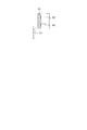
- the first intermediate member 60 further includes a protrusion 67.
- the protrusion 67 extends from the front surface of the first intermediate member main body 61 toward the front.
- the protrusion 67 is used to urge the first intermediate member 60 toward the first non-mounting position (see FIGS. 4 and 9) by a spring 68 (see FIG. 7) described later.
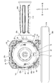
- the second intermediate member 70 includes a base 71, a pressed portion 72, a blocking portion 73, support portions 74 and 75, and a spring seat 78.
- the base 71 is a flat plate-shaped portion having a longitudinal direction in the front-rear direction and orthogonal to a vertical direction.
- the pressed portion 72 is a portion that is pressed upward by the mounting portion 320 of the cover 300 when the cover 300 is attached to the second mounting portion 22, and is located at the front end of the second intermediate member 70. There is.
- the pressed portion 72 has a flat plate shape parallel to the base 71.
- a step portion is formed between the base 71 and the pressed portion 72.
- the amount of displacement of the second intermediate member 70 when the cover 300 is attached can be reduced.
- the second is from the state in which the attachment portion 320 of the cover 300 is lifted to the same position as the base 71 to the state in which the attachment portion 320 abuts on the pressed portion 72. Since the intermediate member 70 is not displaced, the displacement amount of the second intermediate member 70 is reduced by the amount of the step as compared with the configuration in which the pressed portion 72 is in the same vertical position as the base 71. Therefore, the displacement space of the second intermediate member 70 can be reduced. In other words, it is possible to prevent the grinder 10 from increasing in size in the vertical direction.
- the blocking portion 73 is a portion that blocks the light emitted from the sensor 80 when the second intermediate member 70 is in the second mounting position.
- the blocking portion 73 is located at the rear end of the second intermediate member 70, and extends upward from the rear end of the base 71.
- the blocking portion 73 has a flat plate shape orthogonal to the front-rear direction.
- the support portions 74 and 75 are arranged in the vicinity of the cutoff portion 73 on the front side of the cutoff portion 73 so as to face each other in the left-right direction.
- the support portions 74 and 75 have a substantially L-shaped shape extending from the base 71 in the left-right direction away from each other, and then bending and extending upward.
- the support portions 74 and 75 are formed with third through holes 76 and 77 that penetrate the support portions 74 and 75 in the front-rear direction, respectively.
- the third through holes 76 and 77 are in the form of elongated holes whose longitudinal direction is the vertical direction (that is, the direction in which the cover 300 moves linearly when pressed).
- the second intermediate member 70 is screwed to the holding member 140 through the third through holes 76 and 77. Specifically, bolts 92 are inserted into the third through holes 76 and 77 as shown in FIGS. 9 to 11. The bolt 92 is screwed into the screw holes 145a and 146a of the holding member 140, which will be described later.
- the second intermediate member 70 is a holding member that can move linearly along the third through holes 76 and 77. It is held at 140. According to this configuration, the second intermediate member 70 can be held with a simple configuration.
- the spring seat 78 is provided so as to project upward from the base 71.
- a spring 79 is held between the spring seat 78 and the spring seat 148 (see FIG. 7) of the holding member 140 (see FIG. 4).
- the spring 79 urges the second intermediate member 70 toward the second non-mounting position (see FIGS. 4, 9 and 10).
- the holding member 140 includes an annular portion 141, a cylindrical portion 142, a protruding portion 143, 144, a protruding portion 145, 146, a spring seat 148, and a spring accommodating portion 149.
- the annulus 141 has a disk shape centered on the rotation axis AX1 of the electric motor 31, and a through hole is formed in the center thereof.
- a notch 147 is formed on the lower side of the annulus 141 in order to secure a displacement space for the second intermediate member 70.
- the cylindrical portion 142 has a cylindrical shape extending from the annular portion 141 toward the rear side.
- the diameter of the cylindrical portion 142 is smaller than the diameter of the annular portion 141.
- a spring accommodating portion 149 is formed on the upper side of the cylindrical portion 142 adjacent to the cylindrical portion 142.
- the spring accommodating portion 149 is formed in an arc shape centered on the rotation axis AX1.
- a spring 68 that can be expanded and contracted along the arc shape of the spring accommodating portion 149 is accommodated in the spring accommodating portion 149.
- the rear side of the spring accommodating portion 149 is open, and the protrusion 67 of the first intermediate member 60 is inserted into the spring accommodating portion 149 through this opening.
- One end of the spring 68 is supported by the inner surface of the spring accommodating portion 149 (a plane located at one end of the arc shape), and the other end of the spring 68 engages with the protrusion 67.
- the first intermediate member 60 is urged in the clockwise direction (in other words, toward the first non-mounting position).
- the protrusions 143 and 144 are arranged apart from each other in the left-right direction.
- the protruding portions 143 and 144 extend from the annular portion 141 toward the rear side at substantially the center of the annular portion 141 in the vertical direction.
- the protrusions 143 and 144 have screw holes 143a and 144a on which female screws are formed, respectively.
- the screw holes 143a and 144a extend from the rear end faces of the protrusions 143 and 144 toward the front side.
- Bolts 91 are screwed into the screw holes 143a and 144a in order to attach the first intermediate member 60 to the holding member 140 in the manner described above (see FIG. 9).
- the protrusions 145 and 146 are arranged below the protrusions 143 and 144 so as to be separated from each other in the left-right direction.
- the protrusions 145 and 146 have screw holes 145a and 146a on which female screws are formed, respectively.
- the screw holes 145a and 146a extend from the rear end faces of the protrusions 145 and 146 toward the front side.
- Bolts 92 are screwed into the screw holes 145a and 146a in order to attach the second intermediate member 70 to the holding member 140 in the manner described above (see FIG. 9).
- the length of the protrusions 145 and 146 in the front-rear direction is smaller than the length of the protrusions 143 and 144 in the front-rear direction.
- the above-mentioned spring seat 148 is formed at the lower end of the cylindrical portion 142.
- the holding member 140 With the first intermediate member 60 and the second intermediate member 70 attached, the outer circumference of the annular portion 141 and the inner circumference of the cylindrical portion 142 come into contact with the gear housing 20. It is fitted in the gear housing 20. Thereby, the holding member 140 is fixed to the gear housing 20.
- the first intermediate member 60 and the second intermediate member 70 are attached to the single holding member 140, the relative positions of the first intermediate member 60 and the second intermediate member 70 are naturally determined, so that the grinder At the time of assembling 10, it is not necessary to adjust the relative positions of the first intermediate member 60 and the second intermediate member 70.
- the holding member 140 holds the sensor substrate holding member 85 that holds the sensor 80 and the first intermediate member 60 together. Therefore, when the sensor substrate holding member 85 is attached, the relative positions of the sensor 80 with respect to the first intermediate member 60 and the second intermediate member 70 are naturally determined, so that the position adjustment of the sensor 80 is not necessary.
- the sensor 80 is a reflective photo sensor in this embodiment.
- the sensor 80 includes a light emitting unit 82, a light receiving unit 83, and a sensor substrate 81 on which the light emitting unit 82 and the light receiving unit 83 are mounted together.
- the light emitting unit 82 and the light receiving unit 83 are arranged on the front surface of the sensor substrate 81.
- the sensor 80 is arranged near the bottom of the gear housing 20 in order to detect the displacement of the first intermediate member 60 and the second intermediate member 70. More specifically, the sensor substrate 81 and the light emitting unit 82 are arranged on the rear side of the first intermediate member main body 61 in the vicinity of the first intermediate member main body 61.
- the sensor 80 is held by the sensor substrate holding member 85 shown in FIG.
- the sensor substrate holding member 85 is a substantially Y-shaped plate-shaped member.
- a sensor substrate 81 on which a light emitting unit 82 and a light receiving unit 83 are mounted is held at a bifurcated base of the sensor substrate holding member 85.
- the sensor substrate 81 is fixed to the sensor substrate holding member 85 by any method (for example, screwing, snap fitting, engagement by partially heating and deforming, etc.). Further, through holes 87 and 88 are formed in the vicinity of the bifurcated tip of the sensor substrate holding member 85.
- the first intermediate member 60 is displaced between a position that blocks the light emitted from the light emitting unit 82 and a position that does not block the light due to the attachment of the side handle 200.
- the second intermediate member 70 is displaced between a position that blocks the light emitted from the light emitting unit 82 and a position that does not block the light due to the attachment of the cover 300.
- the sensor 80 detects the state in which the side handle 200 and the cover 300 are attached depending on the presence or absence of light reception by the light receiving unit 83 based on the difference in the positions of the first intermediate member 60 and the second intermediate member 70.
- FIG. 12 illustrates the positional relationship between the first intermediate member 60 and the second intermediate member 70 (see FIGS. 4 and 9) and the sensor 80 when neither the side handle 200 nor the cover 300 is attached. Is shown.
- the first intermediate member 60 is at a position where the first intermediate member main body 61 blocks the light emitted from the light emitting unit 82. Is located in. Since the first intermediate member main body 61 is close to the light emitting unit 82 and the light receiving unit 83, the light receiving unit 83 cannot receive the light emitted from the light emitting unit 82.
- the first intermediate member main body 61 is in the position shown in FIG. 12 even when only the cover 300 of the side handle 200 and the cover 300 is attached, so that the light receiving unit 83 is the light emitting unit. The light emitted from 82 cannot be received.
- the first intermediate member 60 When only the side handle 200 is attached to the state shown in FIG. 12, the first intermediate member 60 is displaced to the first attachment position shown in FIGS. 3 and 10. At this time, as shown in FIG. 13, since the light 89 emitted from the light emitting unit 82 passes through the second through hole 64, it is not blocked by the first intermediate member main body 61. Further, at this time, since the blocking portion 73 of the second intermediate member 70 is in a position that does not block the light 89, the light receiving portion 83 cannot receive the light emitted from the light emitting unit 82.
- the second intermediate member 70 is displaced to the second attachment position shown in FIGS. 3 and 11.
- the light 89 emitted from the light emitting unit 82 passes through the second through hole 64 and is then blocked by the blocking unit 73.
- the light 89 is reflected by the blocking unit 73 and received by the light receiving unit 83.
- the light 89 emitted from the light emitting unit 82 is received by the light receiving unit 83 in one sensor 80 only when both the side handle 200 and the cover 300 are attached. be able to. That is, one sensor 80 can detect a state in which both the side handle 200 and the cover 300 are attached. Therefore, the number of parts and the cost can be reduced as compared with the configuration in which individual sensors are provided for each of the side handle 200 and the cover 300.
- the first intermediate member 60 is configured to rotate about the rotation axis AX1 when any of the pressed portions 62a to 62c is pressed by the side handle 200. Therefore, it is not necessary to secure the displacement space of the first intermediate member 60 in the front-rear direction, so that the size of the grinder 10 in the front-rear direction can be made compact.
- the second intermediate member 70 is pressed against the cover 300 (more specifically, the attachment portion 320) and is directly in the attachment direction (that is, upward direction) of the cover 300. Move. Therefore, a direction changing mechanism is not required, and the device configuration can be simplified.
- the second embodiment of the present invention will be described with reference to FIGS. 15 and 16.
- the sensor 180 is used instead of the sensor 80, the first intermediate member 160 is used instead of the first intermediate member 60, and the second intermediate member 70 is replaced.
- the second intermediate member 170 is used, which is different from the first embodiment.
- FIGS. 15 and 16 the same components as those of the first embodiment are designated by the same reference numerals as those of the first embodiment.
- the sensor 180 is a transmissive photo sensor in this embodiment. As shown in FIGS.
- the senor 180 includes a light emitting unit 182, a light receiving unit 183, and a sensor substrate 181 on which the light emitting unit 182 and the light receiving unit 183 are mounted together.
- the first intermediate member 160 does not have the second through hole 64, but instead has a notch at the outer edge in the radial direction.
- the second intermediate member 170 includes a blocking portion 173 instead of the blocking portion 73. The blocking portion 173 extends downward from the rear end of the base 71.
- the light emitting unit 182 and the light receiving unit 183 are arranged so that the blocking unit 173 and the first intermediate member main body 61 are located between the light emitting unit 182 and the light receiving unit 183 in the front-rear direction.
- the first intermediate member 160 when the first intermediate member 160 is in the first non-mounting position, the first intermediate member main body 61 is in a position to block the light emitted from the light emitting unit 182, and the second intermediate member 170 Is in the first non-mounting position, the blocking section 173 is in a position to block the light emitted from the light emitting section 182 (see FIG. 16).
- the light emitted from the light emitting unit 182 is blocked by at least one of the first intermediate member 160 and the second intermediate member 170. .. Therefore, the light receiving unit 183 cannot receive the light emitted from the light emitting unit 182.
- the first intermediate member 160 is in the first mounting position
- the light emitted from the light emitting unit 182 can pass through the notch of the first intermediate member 160
- the second intermediate member 170 is the first.
- the blocking section 173 is displaced to a position where it does not block the light emitted from the light emitting section 182 (see FIG. 15).
- the state in which both the side handle 200 and the cover 300 are attached can be detected by one sensor 180.
- the shape and form of the components of the grinder 10 described above are merely examples, and any changes can be made as long as the operation of the components is ensured.
- the pressed portions 62a to 62c of the first intermediate member 60 may project forward or rearward instead of projecting radially outward.
- the first intermediate member 60 may include a blocking portion that protrudes radially outward from the first intermediate member main body 61 instead of the second through hole 64. In this case, when the first intermediate member 60 is in the first non-mounting position, the blocking portion blocks the light emitted from the light emitting unit 82, and when the first intermediate member 60 is in the first mounting position. Is in a state where the blocking unit is displaced to a position where the light emitted from the light emitting unit 82 is not blocked.
- first intermediate member 60 may be indirectly pressed by the side handle 200 when the side handle 200 is attached. That is, an additional member that is pressed and displaced by the side handle 200 is provided, and the additional member may displace the first intermediate member 60.
- second intermediate member 70 may be indirectly pressed by the cover 300 when the cover 300 is attached.
- first intermediate member 60 may be configured to be pressed by the side handle 200 and tilted when the side handle 200 is attached, instead of rotating when the side handle 200 is attached. good.
- first intermediate member 60 has a support shaft on the lower side of the first intermediate member 60, and is inclined so that the lower end of the first intermediate member 60 approaches the front side with the support shaft as the center. May be good.
- the second intermediate member 70 is at a position that blocks the light emitted from the light emitting unit 82 at the second non-mounting position, and is at a position that does not block the light emitted from the light emitting unit 82 at the second mounting position. May be good.
- the second intermediate member 70 is coated with a low-reflection paint, and the reflector is placed between the reflector and the sensor 80 in the front-rear direction with the first intermediate member 60 and the second intermediate member. It may be arranged so that 70 is located. In this way, the light receiving unit 83 can receive the light emitted from the light emitting unit 82 only when both the side handle 200 and the cover 300 are attached.
- the sensors 80 and 180 are not limited to photoelectric sensors, and may be sensors of other known types.
- an ultrasonic distance sensor may be used.
- the position where the first intermediate member 60 and the second intermediate member 70 block the ultrasonic waves transmitted from the sensor depending on whether or not the side handle 200 or the cover 300 is attached (hereinafter, also referred to as a blocking position). )
- a position that does not block the ultrasonic wave hereinafter, also referred to as a non-blocking position, if it is configured to be displaced, it is possible to detect a state in which both the side handle 200 and the cover 300 are attached.
- the first intermediate member 60 may take a blocking position when the side handle 200 is not attached, and may take a non-blocking position when the side handle 200 is attached.
- the second intermediate member 70 may take a blocking position when the cover 300 is not attached, and may take a non-blocking position when the cover 300 is attached.
- an eddy current displacement sensor may be used.
- each of the first intermediate member 60 and the second intermediate member 70 is formed of at least a part of metal.
- a color sensor may be used.
- the first intermediate member 60 and the second intermediate member 70 are colored differently from each other.
- the grinder 10 is at least one of the side handle 200 and the cover 300. It may be provided with a notification unit for notifying the user that is not attached.
- the mode of notification may be light emission, pronunciation, character display, or a combination thereof.
- the notification unit may include at least one of a light emitting element such as an LED, a GUI screen, and a speaker.
- the above-described embodiment is applicable not only to the grinder 10 but also to any tool to which two types of accessories can be detachably attached.
Landscapes
- Engineering & Computer Science (AREA)
- Mechanical Engineering (AREA)
- Finish Polishing, Edge Sharpening, And Grinding By Specific Grinding Devices (AREA)
- Constituent Portions Of Griding Lathes, Driving, Sensing And Control (AREA)
- Grinding-Machine Dressing And Accessory Apparatuses (AREA)
- Portable Power Tools In General (AREA)
Priority Applications (3)
| Application Number | Priority Date | Filing Date | Title |
|---|---|---|---|
| DE112021001490.0T DE112021001490T5 (de) | 2020-04-10 | 2021-04-08 | Werkzeug |
| CN202180025003.9A CN115397623B (zh) | 2020-04-10 | 2021-04-08 | 工具 |
| US17/914,949 US12194596B2 (en) | 2020-04-10 | 2021-04-08 | Tool with single sensor to detect attachment of side grip and cover |
Applications Claiming Priority (2)
| Application Number | Priority Date | Filing Date | Title |
|---|---|---|---|
| JP2020071239A JP7398325B2 (ja) | 2020-04-10 | 2020-04-10 | 工具 |
| JP2020-071239 | 2020-04-10 |
Publications (1)
| Publication Number | Publication Date |
|---|---|
| WO2021206139A1 true WO2021206139A1 (ja) | 2021-10-14 |
Family
ID=78023568
Family Applications (1)
| Application Number | Title | Priority Date | Filing Date |
|---|---|---|---|
| PCT/JP2021/014892 Ceased WO2021206139A1 (ja) | 2020-04-10 | 2021-04-08 | 工具 |
Country Status (5)
| Country | Link |
|---|---|
| US (1) | US12194596B2 (enExample) |
| JP (1) | JP7398325B2 (enExample) |
| CN (1) | CN115397623B (enExample) |
| DE (1) | DE112021001490T5 (enExample) |
| WO (1) | WO2021206139A1 (enExample) |
Families Citing this family (3)
| Publication number | Priority date | Publication date | Assignee | Title |
|---|---|---|---|---|
| JP7402737B2 (ja) * | 2020-04-10 | 2023-12-21 | 株式会社マキタ | 工具 |
| WO2022246220A1 (en) * | 2021-05-21 | 2022-11-24 | Milwaukee Electric Tool Corporation | Oscillating multi-tool |
| JP2023016165A (ja) * | 2021-07-21 | 2023-02-02 | 株式会社マキタ | 電動工具 |
Citations (3)
| Publication number | Priority date | Publication date | Assignee | Title |
|---|---|---|---|---|
| WO2017051893A1 (ja) * | 2015-09-25 | 2017-03-30 | 株式会社マキタ | グラインダ |
| US20180272494A1 (en) * | 2015-09-29 | 2018-09-27 | Robert Bosch Gmbh | Hand-Held Power Tool Having at Least One Machine-Side Contact Element |
| WO2018180083A1 (ja) * | 2017-03-30 | 2018-10-04 | 工機ホールディングス株式会社 | 回転工具 |
Family Cites Families (6)
| Publication number | Priority date | Publication date | Assignee | Title |
|---|---|---|---|---|
| DE19854468A1 (de) * | 1998-11-25 | 2000-06-08 | Flex Elektrowerkzeuge Gmbh | Handwerkzeugmaschine |
| US7282818B2 (en) * | 2002-04-10 | 2007-10-16 | Credo Technology Corporation | Power hand tool having a proximity detector |
| DE102013202832A1 (de) * | 2013-02-21 | 2014-08-21 | Robert Bosch Gmbh | Handwerkzeugmaschine und Verfahren zum Betreiben der Handwerkzeugmaschine |
| CN112739497B (zh) * | 2018-09-14 | 2023-05-12 | 株式会社牧田 | 工具 |
| JP7402737B2 (ja) * | 2020-04-10 | 2023-12-21 | 株式会社マキタ | 工具 |
| JP2023016165A (ja) * | 2021-07-21 | 2023-02-02 | 株式会社マキタ | 電動工具 |
-
2020
- 2020-04-10 JP JP2020071239A patent/JP7398325B2/ja active Active
-
2021
- 2021-04-08 DE DE112021001490.0T patent/DE112021001490T5/de active Pending
- 2021-04-08 CN CN202180025003.9A patent/CN115397623B/zh active Active
- 2021-04-08 US US17/914,949 patent/US12194596B2/en active Active
- 2021-04-08 WO PCT/JP2021/014892 patent/WO2021206139A1/ja not_active Ceased
Patent Citations (3)
| Publication number | Priority date | Publication date | Assignee | Title |
|---|---|---|---|---|
| WO2017051893A1 (ja) * | 2015-09-25 | 2017-03-30 | 株式会社マキタ | グラインダ |
| US20180272494A1 (en) * | 2015-09-29 | 2018-09-27 | Robert Bosch Gmbh | Hand-Held Power Tool Having at Least One Machine-Side Contact Element |
| WO2018180083A1 (ja) * | 2017-03-30 | 2018-10-04 | 工機ホールディングス株式会社 | 回転工具 |
Also Published As
| Publication number | Publication date |
|---|---|
| JP2021167047A (ja) | 2021-10-21 |
| CN115397623A (zh) | 2022-11-25 |
| DE112021001490T5 (de) | 2023-01-12 |
| US12194596B2 (en) | 2025-01-14 |
| US20230150085A1 (en) | 2023-05-18 |
| CN115397623B (zh) | 2025-08-12 |
| JP7398325B2 (ja) | 2023-12-14 |
Similar Documents
| Publication | Publication Date | Title |
|---|---|---|
| WO2021206139A1 (ja) | 工具 | |
| US10576605B2 (en) | Power tool | |
| US11192270B2 (en) | Portable cutting tool | |
| CN111546294B (zh) | 便携式加工机 | |
| WO2020241086A1 (ja) | 電動工具 | |
| CN210307665U (zh) | 电动工具 | |
| JP7402737B2 (ja) | 工具 | |
| JP6615675B2 (ja) | アタッチメントおよび作業工具 | |
| CN110769976B (zh) | 作业工具 | |
| WO2021206101A1 (ja) | 工具 | |
| US20240399612A1 (en) | Working machine | |
| WO2013176217A1 (ja) | 作業工具 | |
| CN115673957A (zh) | 电动工具 | |
| US20250178151A1 (en) | Rotary tool | |
| US12103127B2 (en) | Power tool | |
| WO2024181502A1 (ja) | 電動工具、電動工具システム、アタッチメント、及び交換式工具システム | |
| JP7107554B2 (ja) | 防塵カバー | |
| WO2025225192A1 (ja) | 電動工具システム、及びアタッチメント | |
| TW202432305A (zh) | 具有快換護罩組的電動切削機 |
Legal Events
| Date | Code | Title | Description |
|---|---|---|---|
| 121 | Ep: the epo has been informed by wipo that ep was designated in this application |
Ref document number: 21784193 Country of ref document: EP Kind code of ref document: A1 |
|
| 122 | Ep: pct application non-entry in european phase |
Ref document number: 21784193 Country of ref document: EP Kind code of ref document: A1 |
|
| WWG | Wipo information: grant in national office |
Ref document number: 202180025003.9 Country of ref document: CN |