WO2021205897A1 - Procédé pour estamper des éléments de forme ronde et rouleau utilisé pour l'estampage - Google Patents
Procédé pour estamper des éléments de forme ronde et rouleau utilisé pour l'estampage Download PDFInfo
- Publication number
- WO2021205897A1 WO2021205897A1 PCT/JP2021/012680 JP2021012680W WO2021205897A1 WO 2021205897 A1 WO2021205897 A1 WO 2021205897A1 JP 2021012680 W JP2021012680 W JP 2021012680W WO 2021205897 A1 WO2021205897 A1 WO 2021205897A1
- Authority
- WO
- WIPO (PCT)
- Prior art keywords
- round
- extracting
- row
- original fabric
- shaped
- Prior art date
Links
Images


Classifications
-
- B—PERFORMING OPERATIONS; TRANSPORTING
- B26—HAND CUTTING TOOLS; CUTTING; SEVERING
- B26D—CUTTING; DETAILS COMMON TO MACHINES FOR PERFORATING, PUNCHING, CUTTING-OUT, STAMPING-OUT OR SEVERING
- B26D9/00—Cutting apparatus combined with punching or perforating apparatus or with dissimilar cutting apparatus
-
- B—PERFORMING OPERATIONS; TRANSPORTING
- B26—HAND CUTTING TOOLS; CUTTING; SEVERING
- B26F—PERFORATING; PUNCHING; CUTTING-OUT; STAMPING-OUT; SEVERING BY MEANS OTHER THAN CUTTING
- B26F1/00—Perforating; Punching; Cutting-out; Stamping-out; Apparatus therefor
-
- B—PERFORMING OPERATIONS; TRANSPORTING
- B26—HAND CUTTING TOOLS; CUTTING; SEVERING
- B26F—PERFORATING; PUNCHING; CUTTING-OUT; STAMPING-OUT; SEVERING BY MEANS OTHER THAN CUTTING
- B26F1/00—Perforating; Punching; Cutting-out; Stamping-out; Apparatus therefor
- B26F1/38—Cutting-out; Stamping-out
- B26F1/44—Cutters therefor; Dies therefor
-
- B—PERFORMING OPERATIONS; TRANSPORTING
- B31—MAKING ARTICLES OF PAPER, CARDBOARD OR MATERIAL WORKED IN A MANNER ANALOGOUS TO PAPER; WORKING PAPER, CARDBOARD OR MATERIAL WORKED IN A MANNER ANALOGOUS TO PAPER
- B31B—MAKING CONTAINERS OF PAPER, CARDBOARD OR MATERIAL WORKED IN A MANNER ANALOGOUS TO PAPER
- B31B50/00—Making rigid or semi-rigid containers, e.g. boxes or cartons
- B31B50/14—Cutting, e.g. perforating, punching, slitting or trimming
- B31B50/16—Cutting webs
Definitions
- the present invention relates to a method for extracting a round-shaped member and a raw material for extracting a round-shaped member, for example, a bottom of a container composed of a bottom formed in a circular shape and a side wall surrounding the bottom, and a container opening.
- the present invention relates to a method for extracting a round-shaped member capable of efficiently and continuously producing a round-shaped member, and a raw fabric used for extracting the round-shaped member.
- Patent Document 1 Patent Document 2
- Patent Document 3 Patent Document 3
- a method such as punching out a plurality of round-shaped members 2 from the original fabric pieces 1a to 1c using 1a to 1c is adopted.
- the remaining portion obtained by extracting the round-shaped member 2 from the raw fabric pieces 1a to 1c is a discarded portion, but the round-shaped member is cut from the raw fabric pieces 1a to 1c cut to a width larger than the diameter of the round-shaped member 2 as in the conventional case.
- the amount of the residual portion after extracting the round-shaped member 2 is large, and as the number of extracted round-shaped members 2 increases, the loss due to the increase in the amount of waste increases, and the round-shaped member 2 It had a great impact on manufacturing costs.
- the present invention has been made in view of the above-mentioned conventional problems, and an object of the present invention is to provide a method for extracting a round-shaped member and a raw material for extracting the round-shaped member, which can efficiently manufacture the round-shaped member at a lower cost. And.
- the present invention (1) A method for manufacturing a round-shaped member in which a plurality of round-shaped members are extracted from a long and wide original fabric in a plurality of rows in the width direction of the original fabric, and one row for extracting a plurality of round-shaped members. , A corrugation between one row and the row adjacent to that row along the outer shape of the round member between the rows so that the position of the round member in the longitudinal direction shifts between the rows adjacent to that row.
- a method for extracting a round-shaped member which comprises extracting a round-shaped member from an original fabric having at least one long side having a wavy shape.
- a long raw fabric for extracting a plurality of round-shaped members in the longitudinal direction, and the original fabric is a row for extracting a plurality of round-shaped members from a long and wide original fabric.
- a raw fabric for extracting round-shaped members which is characterized in that it is cut into a cut corrugated shape.
- the raw fabric for extracting the round-shaped member is a position in which the positions of the one row and the row adjacent to the one row in the longitudinal direction of the round-shaped member to be extracted are deviated from each other.
- the raw fabric for extracting the round-shaped member is adjacent to the one row and the row adjacent to the one row for extracting a plurality of round-shaped members.
- a wide original fabric is cut in a corrugated manner between the one row and the row adjacent to the row so that the positions of the round members to be extracted in the longitudinal direction are offset from each other.
- the original fabric for extracting the round-shaped member according to (10) above which is cut out from the above and then wound into a roll.
- the original fabric for extracting a round member according to (10) above, wherein the original fabric for extracting a round member is a material containing a paper material.
- the original fabric for extracting a round member is a composite material obtained by laminating a plurality of materials.
- the method for extracting a plurality of round-shaped members of the present invention includes a single row for extracting a plurality of round-shaped members when extracting a plurality of round-shaped members from a long and wide raw fabric in the width direction of the original fabric. , A corrugation between one row and the row adjacent to that row along the outer shape of the round member between the rows so that the position of the round member in the longitudinal direction shifts between the rows adjacent to that row.
- waste can be significantly reduced, and by extension, the manufacturing cost of round members can be greatly reduced.
- the amount of displacement of the round-shaped member in the longitudinal direction in the adjacent row is less than half of the extraction dimension of the round-shaped member in the longitudinal direction, the effective utilization efficiency of the raw fabric can be improved.
- a long side formed by cutting a row for extracting a plurality of round-shaped members and a row adjacent to the row into a corrugated shape along the outer shape of the round-shaped member between the rows is formed.
- the corrugated raw fabric can be wound into a roll once or supplied to the manufacturing process of the container or lid as it is, and the round-shaped member is extracted while extracting the round-shaped member from the original fabric piece.
- the container and the lid can be manufactured in cooperation with each other, and the manufacturing efficiency and the manufacturing cost of the container and the lid can be improved.
- the long side winds up the wavy original fabric in a roll shape, and the long side winds out the wavy original fabric while pulling out the round member to wind up the original fabric.
- it does not require a means such as temporarily storing the pulled-out round-shaped member.
- the process of extracting the round-shaped member and the process of manufacturing the lid, container, etc. using the extracted round-shaped member can be easily performed continuously, and the long side is not wavy.
- the raw fabric for extracting round-shaped members of the present invention can significantly reduce the amount of the residual portion from which the round-shaped members have been extracted when extracting a plurality of round-shaped members from a long original fabric, and effectively utilize resources. As a result, waste can be significantly reduced, and as a result, the manufacturing cost of the round-shaped member can be greatly reduced. Further, between one row for pulling out the round-shaped member and the row adjacent to the row, the round-shaped member to be pulled out in one row and the round-shaped member to be pulled out in the row adjacent to the one row.
- a raw fabric for extracting the round-shaped member by cutting the space between the two rows in a corrugated manner along the outer shape of the round-shaped member so that the two rows are in contact with each other and the positions of the round-shaped member in both rows are displaced in the longitudinal direction. Is preferable. With the raw fabric formed in this way, the amount of the unextracted portion when the round member is extracted from the original fabric can be further reduced.
- the original fabric for extracting the round member of the present invention is once wound into a roll shape, and is in the form of a roll-shaped original fabric, so that it can be easily stored and transferred to the manufacturing process of the container or lid.
- the process of extracting the round-shaped member and the extracted round-shaped member as the bottom of the container or canopy are used.
- the lids can be manufactured in cooperation with each other, and the efficiency and cost of manufacturing the containers and lids can be improved.
- the raw fabric for extracting a round member of the present invention has an advantage that when the round member is extracted from the original fabric, the original fabric can be easily drawn out from the roll.
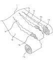
- FIG. 2 shows an embodiment of the present invention, in which 1a, 1b, and 1c indicate an example of a raw fabric for extracting a round member (hereinafter, may be simply referred to as an original fabric).
- At least one of the original fabrics 1a, 1b and 1c in the longitudinal direction is formed in a wavy shape 4, the original fabrics 1a and 1c have a wavy shape 4 on one long side, and the original fabrics 1b have both long sides. It is formed in a wave shape 4.
- the raw fabrics 1a to 1c are formed between a row from which the round-shaped member 2 should be extracted from the wide raw fabric 1 (FIG. 3) and a row adjacent to the row along the outer shape of the round-shaped member 2. It is cut out and formed.
- the original fabric 1a and the original fabric 1b are the original fabric 1a and the original fabric 1b so that the round-shaped member 2 to be extracted from the original fabric 1a and the round-shaped member 2 to be extracted from the original fabric 1b are displaced in the longitudinal direction. Is formed by cutting along the outer shape of the round member 2. Further, the raw fabric 1c is formed along the outer shape of the round-shaped member to be extracted so that the round-shaped member 2 to be extracted from the original fabric 1c is displaced from the round-shaped member 2 to be extracted from the original fabric 1b in the longitudinal direction. It is formed by cutting between 1b and the original fabric 1c.
- the amount of displacement in the longitudinal direction between the round-shaped member 2 to be extracted in the original fabric 1a and the round-shaped member 2 to be extracted in the original fabric 1b, the round-shaped member 2 to be extracted in the original fabric 1b, and the circle to be extracted in the original fabric 1c It is preferable to cut between the original fabrics 1a to 1c so that the amount of displacement in the longitudinal direction from the shape member 2 is less than half the longitudinal dimension of the round member. Further, it is possible to cut the position between the raw fabrics so that the round members 2 to be extracted in each adjacent row are displaced in the longitudinal direction so that the round members between the rows are in contact with each other. This is preferable because the amount of the remaining portion can be reduced.
- the round-shaped member is not limited to a perfect circular shape, but also includes a round-shaped member having a circular shape such as an elliptical shape and a shape similar to a circular shape, and having protrusions or irregularities on the outer circumference. Will be done.
- Examples of the materials constituting the raw fabric include pulp-based materials, fiber-based materials, synthetic resin-based materials, metal-based materials, wood-based materials, glass-based materials, and composites thereof.
- Raw fabrics include, for example, plant fibers and so-called papers produced by laminating other fibers, as well as chemical fiber paper, synthetic paper, water resistant paper, coated paper, alternative paper, sheep skin paper, wool paper, and glass fiber paper. Examples include stone paper and ceramic paper.
- a so-called air-laid sheet formed into a sheet by combining crushed pulp piled up by an air flow, a pulp-based material, a non-woven fabric of fibers such as a natural fiber material and a synthetic fiber, and the like can also be used.
- synthetic resin, natural resin, biodegradable resin film or sheet, metal foil such as aluminum foil, wood foil and the like can also be used as the raw material.
- the material and thickness are not limited, but usually film-like or sheet-like materials are preferable, and paper-based materials, pulp-based materials, resin films and sheets are preferable.
- a metal foil such as an aluminum foil or a laminate thereof is preferable.
- the raw fabric for extracting round members of the present invention can be formed by cutting a wide original fabric in the longitudinal direction, and FIGS. 3 shows the wide original fabrics 1 to 4 rows of raw fabrics for extracting round members 1a to The case where 1d is cut out is shown.
- Each of the original fabrics 1a to 1d cut out from the wide original fabric 1 may be continuously used for extracting the round-shaped member 2, but each of them is wound into a roll shape and temporarily stored as roll-shaped original fabrics 11a to 11d. Then, the process may be started in the process of extracting the round member.
- Each of the original fabrics 1a to 1d is not limited to the case where the round-shaped member 2 is formed as an original fabric for extracting one row of round-shaped members 2 in the width direction, but also for extracting two or more rows of round-shaped members 2. It can be formed as the original fabric of.
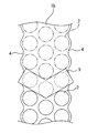
- FIG. 4 shows an example of an original fabric (for example, an original fabric 1b cut out from the wide original fabric 1 shown in FIG. 3) for extracting three rows of round-shaped members 2. Since the original fabric 1b is cut out from the inner portion of the wide original fabric 1, both long sides of the original fabric 1b are formed in a wavy shape 4.
- FIG. 5 shows an example of an original fabric (for example, an original fabric 1c cut out from the wide original fabric 1 shown in FIG. 3) for extracting two rows of round-shaped members 2.
- the round-shaped member extraction raw fabric cut out from the wide original fabric 1 is formed by cutting the round-shaped member 2 to be extracted from the adjacent raw fabric so that the positions in the longitudinal direction are deviated from each other. Therefore, as shown in FIG.
- the wave shapes 4 on both long sides are formed so as to be line-symmetrical on the left and right in the longitudinal direction. Further, as shown in FIG. 5, in the original fabric 1c for extracting the round-shaped members 2 for two rows, the wave shapes on both long sides are line-symmetrical on the left and right, but are shifted by half a pitch in the longitudinal direction from each other. It is formed in a shape.
- both long sides of the original fabrics 1b and 1c are formed in a wavy shape 4, but from the end portion of the wide original fabric 1.
- one long side is formed in a wavy shape and the other long side is formed in a straight line.
- the original fabric for extracting the round-shaped member 2 for an odd number of rows is line-symmetrical on both long sides as the original fabric for extracting the three rows of round-shaped member 2 as the original fabric 1b shown in FIG.
- the wave shape 4 having a shape of the above is formed, or one of the long sides is formed in a straight line.
- the original fabric for extracting an even number of rows of round-shaped members 2 is line-symmetrical on the left and right as the original fabric for extracting two rows of round-shaped members 2 as the original fabric 1c shown in FIG.
- the wave shape has a wave shape 4 having a shape that is half-pitch-shifted from each other in the longitudinal direction, or one of the long sides is formed in a straight line.
- the method can be adopted.
- the punching die 9 for pulling out the round-shaped member 2 from the original fabric is not limited to the examples shown in FIGS. 4 and 5, and has a punching blade arranged according to the number of rows of the round-shaped member 2 to be pulled out. Can be used.
- the raw fabric for extracting the round-shaped member of the present invention should be extracted at the position of the round-shaped member 2 to be extracted in the first row and in the second row adjacent to the first row. It is formed by cutting the space between rows 3 into a wavy shape so that the position of the round member 2 is deviated from the longitudinal direction of the original fabric.
- FIG. 6 shows an example in which three rows of round-shaped members 2 are extracted from the wide original fabric 1, and each of the original fabrics 1a to 1c cut out from the wide original fabric 1 is for one row in the longitudinal direction. An example is shown in which the round member 2 is pulled out.
- each of the original fabrics 1a to 1c is formed by cutting the inter-rows 3 so that the positions of the round-shaped members 2 to be extracted from the original fabrics 1a to 1c are displaced in the longitudinal direction in the adjacent rows.
- the amount of the original fabric 1 used for manufacturing the round-shaped member 2 can be reduced by the width: W3 as shown in FIG.
- the raw material corresponding to the width W3 is reduced by about 14% to 15% as compared with the case where the round member 2 is extracted by the method shown in FIG. Since the same number of round-shaped members 2 as the conventional ones can be extracted even if the amount of raw material used is reduced, the waste of raw material amount can be significantly reduced and the manufacturing cost can be reduced. can.
- the original fabric for extracting a round member of the present invention can be applied not only to the case of extracting a perfect circular member 2 but also to the case of extracting an elliptical round member 2 as shown in FIG.
- FIG. 7 (a) schematically shows a case where an elliptical round member 2 is arranged horizontally and extracted (so that the major axis of the ellipse is in the width direction of the original fabric), and
- FIG. 7 (b) shows an elliptical shape.
- a case where the round-shaped member 2 of the above is arranged diagonally and pulled out is schematically shown.
- the elliptical round member 2 may be arranged vertically (so that the major axis of the ellipse is in the longitudinal direction of the original fabric) and may be extracted. Further, the round-shaped member 2 may have protrusions, irregularities or the like formed on its outer shape.
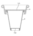
- the round-shaped member 2 extracted from the original fabric for extracting the round-shaped member of the present invention can be used as the bottom portion 5 of the container including the bottom portion 5 and the side wall 6 surrounding the bottom portion 5 as shown in FIG.
- the peripheral edge of the round member 2 is bent to form a bottom portion 5, and the bent portion of the bottom portion 5 is sandwiched and fixed between the lower end portion of the side wall 6 and the bent portion whose lower end portion is bent inward. It is formed.
- it can be used as the canopy portion 7 in the canopy body including the canopy portion 7 and the side portion 8 surrounding the canopy portion 7.
- the lid is formed by bending the peripheral edge of the round member 2 to form a canopy portion 7, sandwiching the bent portion between the lower end portion of the side portion 8 and the bent portion of the lower end portion, and fixing the bent portion.
- the round-shaped member extracted from the original fabric of the present invention is not limited to the case of being used as the bottom 5 of the container or the canopy of the lid as described above, and can also be used for other purposes.
- a seal lid that seals the mouth of a container such as cup noodles or snack confectionery with a round-shaped member manufactured from materials such as synthetic resin film, paper, aluminum foil, and raw fabrics of these composite materials. Can be used as.
- the original fabric for extracting round members of the present invention is in the form of a roll-shaped original fabric that is cut out from a wide original fabric and then wound into a roll shape as described above. It is possible to transfer to the manufacturing process and extract the round-shaped member while feeding out the original fabric from the roll-shaped original fabric, and to manufacture the container and lid using the extracted round-shaped member.
- the original fabric for extracting the round-shaped member may be cut out, the round-shaped member may be extracted, and the extracted round-shaped member may be transferred to the manufacturing process of the container or the lid to manufacture the container or the lid.
- the raw material for extracting the round member is wound into a roll shape to form a roll-shaped raw material, and the container or lid is manufactured using this, the container or lid using the conventional manufacturing equipment is used. The body can be easily manufactured.
- the original fabric for extracting the round-shaped members formed so as to extract the round-shaped members having the same size and shape is shown, but the circles to be extracted in each row are shown.
- the size and shape of the shape member may be different.
- one row and a row adjacent to the row are configured to extract round members of different sizes, or one row is configured to extract a perfect circular round member and adjacent to the row.
- an elliptical round member may be extracted.
Landscapes
- Life Sciences & Earth Sciences (AREA)
- Forests & Forestry (AREA)
- Engineering & Computer Science (AREA)
- Mechanical Engineering (AREA)
- Making Paper Articles (AREA)
Abstract
La présente invention concerne un procédé pour estamper des éléments de forme ronde, lequel procédé sert à produire des éléments de forme ronde, et dans lequel procédé un rouleau long et large est estampé dans de multiples rangées dans le sens de la largeur de celui-ci pour obtenir une pluralité d'éléments de forme ronde. Dans le procédé, des éléments de forme ronde sont estampés à partir du rouleau dans lequel une rangée à partir de laquelle une pluralité d'éléments de forme ronde doivent être estampés et une rangée adjacente à celle-ci sont disposées de façon à amener les rangées à avoir au moins l'un des côtés longitudinaux sous une forme ondulée formée par une découpe ondulée entre les rangées le long des contours des éléments de forme ronde dans la zone entre rangées, de telle sorte que les positions longitudinales des éléments de forme ronde dans la rangée sont hors d'alignement avec celles dans l'autre rangée.
Priority Applications (1)
| Application Number | Priority Date | Filing Date | Title |
|---|---|---|---|
| JP2021517077A JPWO2021205897A1 (fr) | 2020-04-07 | 2021-03-25 |
Applications Claiming Priority (2)
| Application Number | Priority Date | Filing Date | Title |
|---|---|---|---|
| JP2020-069433 | 2020-04-07 | ||
| JP2020069433 | 2020-04-07 |
Publications (1)
| Publication Number | Publication Date |
|---|---|
| WO2021205897A1 true WO2021205897A1 (fr) | 2021-10-14 |
Family
ID=78022927
Family Applications (1)
| Application Number | Title | Priority Date | Filing Date |
|---|---|---|---|
| PCT/JP2021/012680 WO2021205897A1 (fr) | 2020-04-07 | 2021-03-25 | Procédé pour estamper des éléments de forme ronde et rouleau utilisé pour l'estampage |
Country Status (2)
| Country | Link |
|---|---|
| JP (1) | JPWO2021205897A1 (fr) |
| WO (1) | WO2021205897A1 (fr) |
Citations (5)
| Publication number | Priority date | Publication date | Assignee | Title |
|---|---|---|---|---|
| JPS5023932U (fr) * | 1973-06-28 | 1975-03-18 | ||
| JPH02307738A (ja) * | 1989-05-24 | 1990-12-20 | Kyokuto Internatl Corp | 紙カップの製造方法 |
| JPH09277196A (ja) * | 1996-04-10 | 1997-10-28 | Dainippon Printing Co Ltd | フィルム加工方法及び装置 |
| JP2012240695A (ja) * | 2011-05-18 | 2012-12-10 | Toppan Printing Co Ltd | カップ型紙容器およびその製造方法 |
| WO2016069755A1 (fr) * | 2014-10-29 | 2016-05-06 | Westrock Mwv, Llc | Couvercles de gobelets en carton et procédé de fabrication associé |
Family Cites Families (2)
| Publication number | Priority date | Publication date | Assignee | Title |
|---|---|---|---|---|
| JPS5028982U (fr) * | 1973-07-09 | 1975-04-02 | ||
| US4681001A (en) * | 1985-07-01 | 1987-07-21 | Km-Engineering Ag | Method of making scroll strip blanks |
-
2021
- 2021-03-25 JP JP2021517077A patent/JPWO2021205897A1/ja not_active Withdrawn
- 2021-03-25 WO PCT/JP2021/012680 patent/WO2021205897A1/fr active Application Filing
Patent Citations (5)
| Publication number | Priority date | Publication date | Assignee | Title |
|---|---|---|---|---|
| JPS5023932U (fr) * | 1973-06-28 | 1975-03-18 | ||
| JPH02307738A (ja) * | 1989-05-24 | 1990-12-20 | Kyokuto Internatl Corp | 紙カップの製造方法 |
| JPH09277196A (ja) * | 1996-04-10 | 1997-10-28 | Dainippon Printing Co Ltd | フィルム加工方法及び装置 |
| JP2012240695A (ja) * | 2011-05-18 | 2012-12-10 | Toppan Printing Co Ltd | カップ型紙容器およびその製造方法 |
| WO2016069755A1 (fr) * | 2014-10-29 | 2016-05-06 | Westrock Mwv, Llc | Couvercles de gobelets en carton et procédé de fabrication associé |
Also Published As
| Publication number | Publication date |
|---|---|
| JPWO2021205897A1 (fr) | 2021-10-14 |
Similar Documents
| Publication | Publication Date | Title |
|---|---|---|
| US7678036B1 (en) | Ripple bottom pizza box and its associated method of construction | |
| JP4982327B2 (ja) | 衛生用紙入りカートン | |
| EP2050681A1 (fr) | Filière de poinconnage pour boîte en carton avec bande d'arrachement | |
| JP4981785B2 (ja) | ダンネージ転換機及び方法のための選択的に引裂き可能な原材料 | |
| WO2021205897A1 (fr) | Procédé pour estamper des éléments de forme ronde et rouleau utilisé pour l'estampage | |
| KR20020084098A (ko) | 다층 금속 제품의 제조를 위한 장치 및 방법 | |
| JP2012051229A (ja) | 段ボールシートとその罫線加工方法 | |
| JP2005040997A (ja) | スロッタナイフ | |
| KR101728061B1 (ko) | 컬링부를 갖는 일회용 종이접시, 그 제조장치 및 제조방법 | |
| JP5175625B2 (ja) | カートン入りティシュ及びその製造方法 | |
| JP2010052049A (ja) | 抜型 | |
| JP2010017954A (ja) | 段ボールの抜型 | |
| JP5075098B2 (ja) | 段ボール箱及びその抜型 | |
| CN212048538U (zh) | 容器套 | |
| JP4219995B2 (ja) | ジッパー付きカートンの製造方法 | |
| WO2020017584A1 (fr) | Matrice de perforation de feuille de carton ondulé, et procédé de perforation de feuille de carton ondulé | |
| JP7072342B2 (ja) | 二重段ボールシート及びその製造方法 | |
| JP4593059B2 (ja) | ラミネートシート | |
| JP2007145355A (ja) | 衛生用紙入りカートン | |
| CN211469368U (zh) | 一种适合高速生产线的带易撕口盒型 | |
| JP7340854B2 (ja) | 食品包装容器 | |
| JP2012082003A (ja) | 包装容器用の切断刃及び包装容器 | |
| KR102570733B1 (ko) | 곽 휴지 카톤 상자 | |
| JP5504067B2 (ja) | 段ボールの手切れ防止 | |
| JP3227045U (ja) | 食品用包装箱 |
Legal Events
| Date | Code | Title | Description |
|---|---|---|---|
| ENP | Entry into the national phase |
Ref document number: 2021517077 Country of ref document: JP Kind code of ref document: A |
|
| 121 | Ep: the epo has been informed by wipo that ep was designated in this application |
Ref document number: 21784093 Country of ref document: EP Kind code of ref document: A1 |
|
| NENP | Non-entry into the national phase |
Ref country code: DE |
|
| 122 | Ep: pct application non-entry in european phase |
Ref document number: 21784093 Country of ref document: EP Kind code of ref document: A1 |