WO2021205754A1 - 光コネクタ、フェルール、及び光コネクタの製造方法 - Google Patents
光コネクタ、フェルール、及び光コネクタの製造方法 Download PDFInfo
- Publication number
- WO2021205754A1 WO2021205754A1 PCT/JP2021/005913 JP2021005913W WO2021205754A1 WO 2021205754 A1 WO2021205754 A1 WO 2021205754A1 JP 2021005913 W JP2021005913 W JP 2021005913W WO 2021205754 A1 WO2021205754 A1 WO 2021205754A1
- Authority
- WO
- WIPO (PCT)
- Prior art keywords
- fiber
- recess
- optical
- coating
- tip
- Prior art date
- Legal status (The legal status is an assumption and is not a legal conclusion. Google has not performed a legal analysis and makes no representation as to the accuracy of the status listed.)
- Ceased
Links
Images



Classifications
-
- G—PHYSICS
- G02—OPTICS
- G02B—OPTICAL ELEMENTS, SYSTEMS OR APPARATUS
- G02B6/00—Light guides; Structural details of arrangements comprising light guides and other optical elements, e.g. couplings
- G02B6/24—Coupling light guides
- G02B6/36—Mechanical coupling means
- G02B6/38—Mechanical coupling means having fibre to fibre mating means
- G02B6/3807—Dismountable connectors, i.e. comprising plugs
- G02B6/3873—Connectors using guide surfaces for aligning ferrule ends, e.g. tubes, sleeves, V-grooves, rods, pins, balls
- G02B6/3885—Multicore or multichannel optical connectors, i.e. one single ferrule containing more than one fibre, e.g. ribbon type
-
- G—PHYSICS
- G02—OPTICS
- G02B—OPTICAL ELEMENTS, SYSTEMS OR APPARATUS
- G02B6/00—Light guides; Structural details of arrangements comprising light guides and other optical elements, e.g. couplings
- G02B6/24—Coupling light guides
- G02B6/36—Mechanical coupling means
- G02B6/38—Mechanical coupling means having fibre to fibre mating means
- G02B6/3807—Dismountable connectors, i.e. comprising plugs
- G02B6/381—Dismountable connectors, i.e. comprising plugs of the ferrule type, e.g. fibre ends embedded in ferrules, connecting a pair of fibres
- G02B6/3825—Dismountable connectors, i.e. comprising plugs of the ferrule type, e.g. fibre ends embedded in ferrules, connecting a pair of fibres with an intermediate part, e.g. adapter, receptacle, linking two plugs
-
- G—PHYSICS
- G02—OPTICS
- G02B—OPTICAL ELEMENTS, SYSTEMS OR APPARATUS
- G02B6/00—Light guides; Structural details of arrangements comprising light guides and other optical elements, e.g. couplings
- G02B6/24—Coupling light guides
- G02B6/36—Mechanical coupling means
- G02B6/38—Mechanical coupling means having fibre to fibre mating means
- G02B6/3807—Dismountable connectors, i.e. comprising plugs
- G02B6/3833—Details of mounting fibres in ferrules; Assembly methods; Manufacture
- G02B6/3834—Means for centering or aligning the light guide within the ferrule
- G02B6/3838—Means for centering or aligning the light guide within the ferrule using grooves for light guides
- G02B6/3839—Means for centering or aligning the light guide within the ferrule using grooves for light guides for a plurality of light guides
-
- G—PHYSICS
- G02—OPTICS
- G02B—OPTICAL ELEMENTS, SYSTEMS OR APPARATUS
- G02B6/00—Light guides; Structural details of arrangements comprising light guides and other optical elements, e.g. couplings
- G02B6/24—Coupling light guides
- G02B6/36—Mechanical coupling means
- G02B6/38—Mechanical coupling means having fibre to fibre mating means
- G02B6/3807—Dismountable connectors, i.e. comprising plugs
- G02B6/3833—Details of mounting fibres in ferrules; Assembly methods; Manufacture
- G02B6/3853—Lens inside the ferrule
-
- G—PHYSICS
- G02—OPTICS
- G02B—OPTICAL ELEMENTS, SYSTEMS OR APPARATUS
- G02B6/00—Light guides; Structural details of arrangements comprising light guides and other optical elements, e.g. couplings
- G02B6/24—Coupling light guides
- G02B6/36—Mechanical coupling means
- G02B6/38—Mechanical coupling means having fibre to fibre mating means
- G02B6/3807—Dismountable connectors, i.e. comprising plugs
- G02B6/3833—Details of mounting fibres in ferrules; Assembly methods; Manufacture
- G02B6/3863—Details of mounting fibres in ferrules; Assembly methods; Manufacture fabricated by using polishing techniques
-
- G—PHYSICS
- G02—OPTICS
- G02B—OPTICAL ELEMENTS, SYSTEMS OR APPARATUS
- G02B6/00—Light guides; Structural details of arrangements comprising light guides and other optical elements, e.g. couplings
- G02B6/24—Coupling light guides
- G02B6/36—Mechanical coupling means
- G02B6/38—Mechanical coupling means having fibre to fibre mating means
- G02B6/3807—Dismountable connectors, i.e. comprising plugs
- G02B6/3897—Connectors fixed to housings, casing, frames or circuit boards
Definitions
- the present disclosure relates to optical connectors, ferrules, and methods of manufacturing optical connectors.
- This application claims priority based on Japanese Application No. 2020-070809 filed on April 10, 2020, and incorporates all the contents described in the Japanese application.
- Patent Document 1 discloses an optical connector for connecting a plurality of optical fibers to a plurality of optical fibers to be connected.
- the optical connector includes a plurality of optical fibers and a ferrule that holds the plurality of optical fibers.
- the ferrule has a ferrule body in which a plurality of fiber holes for holding a plurality of optical fibers are formed, and a lens plate arranged on the front end surface of the ferrule body.
- the optical connector according to the embodiment of the present disclosure includes a plurality of optical fibers having a coating stripping portion from which a predetermined length of coating has been removed from the tip, a main body portion holding the coating stripping portion of each optical fiber, and each optical fiber.
- a ferrule having a lens portion facing the tip in the first direction in which the optical axis of the fiber extends is provided.
- the main body portion has a base portion including a plurality of fiber grooves each supporting a plurality of optical fiber decoating portions.
- the plurality of fiber grooves extend along the first direction and are arranged along the second direction intersecting the first direction.
- the base portion has a recess between each fiber groove in the first direction and the lens portion.
- the ferrule according to the embodiment of the present disclosure includes a main body portion for holding a plurality of optical fibers and a lens portion provided on the tip end side of each optical fiber held in the main body portion.
- the main body has a base including a plurality of fiber grooves for supporting each of the plurality of optical fibers.
- the plurality of fiber grooves extend along the first direction and are arranged along the second direction intersecting the first direction.
- the base portion has a recess between each fiber groove in the first direction and the lens portion.
- the method for manufacturing an optical connector includes a step of preparing a plurality of optical fibers having a coating stripping portion from which a coating having a predetermined length has been removed from the tip, and the above-mentioned ferrule, and coating stripping.
- a step of forming a tip surface in the coating removing portion by laser cutting the portion and a step of placing each optical fiber in each fiber groove of the ferrule described above are provided.
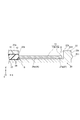
- FIG. 1 is a top view showing an optical connector according to an embodiment.
- FIG. 2 is a top view of the optical connector showing a part of the optical connector of FIG. 1 in cross section.
- FIG. 3 is a cross-sectional view of the optical connector along lines III-III of FIG.
- FIG. 4 is an enlarged cross-sectional view of a part of the coating removal portion of FIG.
- FIG. 5A is a front view of the ferrule.
- FIG. 5B is a rear view of the ferrule showing a part of the ferrule in cross section.
- FIG. 6A is a cross-sectional view showing a method of manufacturing an optical connector according to an embodiment.
- FIG. 6B is a schematic cross-sectional view showing the subsequent steps of FIG. 6A.
- FIG. 7A is a schematic cross-sectional view showing the subsequent steps of FIG. 6B.
- FIG. 7B is a schematic cross-sectional view showing the subsequent steps of FIG. 7A.
- FIG. 7C is a schematic cross-sectional view showing the subsequent steps of FIG. 7B.
- the cut portion of the optical fiber (that is, the tip portion near the tip surface of the optical fiber) tends to be thicker than the other parts of the optical fiber due to the heat of the laser. If the tip portion is thickened in this way, it may be difficult to insert the optical fiber into the fiber hole.
- the optical fiber can be easily mounted while suppressing the occurrence of misalignment of the optical fiber.
- the optical connector according to the embodiment of the present disclosure includes a plurality of optical fibers having a coating stripping portion from which a predetermined length of coating has been removed from the tip, a main body portion holding the coating stripping portion of each optical fiber, and each optical fiber.
- a ferrule having a lens portion facing the tip in the first direction in which the optical axis of the fiber extends is provided.
- the main body portion has a base portion including a plurality of fiber grooves each supporting a plurality of optical fiber decoating portions.
- the plurality of fiber grooves extend along the first direction and are arranged along the second direction intersecting the first direction.
- the base portion has a recess between each fiber groove in the first direction and the lens portion.
- the ferrule base portion has a recess between the plurality of fiber grooves and the lens portion. Since the recesses are present between the plurality of fiber grooves and the lens portion, it is possible to secure a space in the base portion that allows the coating removal portion to be thickened. Therefore, even if the coating removal portion becomes thick, each optical fiber is placed in each fiber groove so that the thickness of the coating removal portion is accommodated in the recess when mounting each optical fiber on the ferrule. Then, each optical fiber can be easily mounted on the ferrule without being hindered by the thickness of the coating removing portion.
- the coating removing portion may include a tip surface located at the tip.
- the tip surface may be inclined with respect to a surface perpendicular to the first direction. In this case, it is possible to suppress the incident of the return light to the optical fiber on the tip surface of the optical fiber.
- the coating removing portion is located between the tip surface located at the tip, the first portion separated from the tip surface in the first direction, and the tip surface and the first portion in the first direction, and is larger than the first portion. It may include a second portion having a maximum outer diameter.
- Each fiber groove may support a first portion of each optical fiber.
- the recess may accommodate a second portion of each optical fiber. For example, when the tip surface of the coating removal portion is formed by laser cutting, the second portion near the tip surface tends to be thickened. Therefore, when each optical fiber is mounted on the ferrule, the above-mentioned effect is suitably exhibited by placing each optical fiber in each fiber groove so that the thickened second portion is accommodated in the recess.
- the width of the recess in the first direction may be larger than the length of the second portion in the first direction. In this case, it is possible to more reliably realize a configuration in which the recess accommodates the second portion of each optical fiber.
- the bottom of the recess may be separated from the decoating portion in a third direction that intersects the first and second directions. In this case, it is possible to more reliably secure a space in the base portion that allows the coating removal portion to be thickened.
- the main body portion may further have a lid portion facing the base portion via each optical fiber in the first direction and the third direction intersecting the second direction.
- the lid portion is a region of the region facing the base portion excluding the region facing the recess, and may be arranged in the region facing each fiber groove. In this case, by pressing each optical fiber into each fiber groove by the lid portion, the misalignment of each optical fiber can be effectively suppressed. Further, in this configuration, the lid is not arranged in the region facing the recess. As a result, it is possible to suppress a situation in which the pressing of each optical fiber into each fiber groove by the lid portion is hindered by the thickness of the coating removing portion in the recess.
- An adhesive for fixing a plurality of optical fibers to the main body may be provided inside the recess. In this case, by fixing each optical fiber to the main body with an adhesive, the misalignment of each optical fiber can be effectively suppressed.
- the base portion may further have a step portion on the side opposite to the concave portion with each fiber sandwiched in the first direction.
- Each optical fiber may further have a covering portion in which the coating remains.
- the stepped surface formed between the covering portion and the coating removing portion by the coating may be in contact with the stepped portion in the first direction. In this case, the position of the tip surface of the coating removing portion inside the recess can be adjusted in the first direction by bringing the stepped surface between the covering portion and the coating removing portion into contact with the stepped portion in the first direction.
- the position of the tip surface can be defined as a position that does not abut on the lens portion, so that it is possible to prevent problems such as tilting of each fiber due to the contact of the tip surface with the lens portion. As a result, the occurrence of misalignment of each optical fiber can be effectively suppressed.
- the lens portion may include a front end surface facing the side opposite to the base portion in the first direction, and a plurality of lenses provided corresponding to the plurality of optical fibers and projecting from the front end surface.
- the outer surface of the ferrule may have a groove as a reference for measuring the position of each lens and the position of each fiber groove as seen from the first direction.
- the groove may extend continuously along the first direction from the lens portion to the main body portion. In this case, by measuring the position of each lens with respect to the position of the groove when viewed from one side in the first direction and the position of each fiber groove with respect to the position of the groove when viewed from the other side in the first direction. , The deviation between the position of each lens and the position of each fiber groove can be measured.
- the ferrule according to the embodiment of the present disclosure includes a main body portion for holding a plurality of optical fibers and a lens portion provided on the tip end side of each optical fiber held in the main body portion.
- the main body has a base including a plurality of fiber grooves for supporting each of the plurality of optical fibers.
- the plurality of fiber grooves extend along the first direction and are arranged along the second direction intersecting the first direction.
- the base portion has a recess between each fiber groove in the first direction and the lens portion.
- the base portion has a recess between the plurality of fiber grooves and the lens portion. Therefore, even when the optical fiber becomes thick, the presence of the recesses between the plurality of fiber grooves and the lens portion ensures a space in the base portion that allows the thickening. Therefore, when each optical fiber is mounted on the ferrule, if each optical fiber is placed in each fiber groove so that the portion where the thickness is generated in each optical fiber is accommodated in the recess, the thickness is not hindered by the thickness. , Each optical fiber can be easily mounted on a ferrule.
- the method for manufacturing an optical connector includes a step of preparing a plurality of optical fibers having a coating stripping portion from which a coating having a predetermined length has been removed from the tip, and the above-mentioned ferrule, and coating stripping.
- a step of forming a tip surface in the coating removing portion by laser cutting the portion and a step of placing each optical fiber in each fiber groove of the ferrule described above are provided.
- each optical fiber is placed in each fiber groove.
- the base portion of the ferrule has a recess between the plurality of fiber grooves and the lens portion. Due to the presence of recesses between the plurality of fiber grooves and the lens portion, a space is secured in the base portion to allow the coating removal portion to become thick. Therefore, even if the coating removal portion becomes thick, each optical fiber is placed in each fiber groove so that the thickness of the coating removal portion is accommodated in the recess when mounting each optical fiber on the ferrule.
- each optical fiber can be easily mounted on the ferrule without being hindered by the thickness of the coating removing portion. Further, in this manufacturing method, since only the thickness of the coating removal portion can be released to the recess, it is not necessary to unnecessarily widen the width of each fiber groove according to the thickness of the coating removal portion. As a result, it is possible to suppress the situation where the clearance between each optical fiber and each fiber groove is expanded, and it is possible to suppress the positional deviation of each optical fiber.
- the tip surface may be inclined with respect to a surface perpendicular to the first direction. In this case, it is possible to suppress the incident of the return light to the optical fiber on the tip surface of the optical fiber.
- the above-mentioned manufacturing method of the optical connector includes a step of injecting an adhesive for fixing a plurality of optical fibers into the main body into the recess and a step of injecting the adhesive into the recess after the step of mounting each optical fiber.
- a step of arranging the lid portion so as to face the base portion via each optical fiber in the third direction intersecting the first direction and the second direction may be further provided.
- the lid portion may be arranged in a region excluding the region facing the recess.
- the misalignment of each optical fiber with respect to the ferrule can be effectively suppressed. Further, by pressing each optical fiber into each fiber groove by the lid portion, the misalignment of each optical fiber can be effectively suppressed. Further, by preventing the lid portion from being arranged in the region facing the recess, it is possible to suppress a situation in which the pressing of each optical fiber into each fiber groove by the lid portion is hindered by the thickness of the coating removing portion.
- FIG. 1 is a top view showing the optical connector 1 according to the present embodiment.
- FIG. 2 is a top view of the optical connector 1 showing a part of the optical connector 1 of FIG. 1 in cross section.
- FIG. 3 is a cross-sectional view of the optical connector 1 along the line III-III of FIG.
- the adhesive A is omitted.
- the X direction which is the connection direction between the optical connector 1 and the optical connector of the connection partner, is the first direction
- the Y direction orthogonal to the X direction is the second direction
- the Z direction is the third direction.
- the explanation may be given by defining the directions as "front” and "rear”.
- the optical connector side of the connection partner with respect to the optical connector 1 is the front, and the opposite side is the rear.
- the optical connector 1 includes a tape fiber T including a plurality of optical fibers 10 and a ferrule 20 into which a front end portion of the tape fiber T is inserted.
- the ferrule 20 has a main body portion 21 that holds each optical fiber 10 of the tape fiber T, and a lens portion 22 provided on the front end surface 21a of the main body portion 21.
- the main body 21 has a substantially rectangular parallelepiped appearance.
- the main body 21 has a base 23 and a lid 24 facing each other in the Z direction.
- the base portion 23 is a portion that supports each optical fiber 10.
- the base portion 23 is integrally formed with the lens portion 22.
- the base portion 23 is made of a light-transmitting resin such as, for example, polyetherimide (PEI), polycarbonate (PC), polymethylmethacrylate (PMMA), or polyethersulfone (PES).
- the base portion 23 includes a plurality of fiber grooves 26 that support each optical fiber 10, a recess 27 formed in front of the plurality of fiber grooves 26, and a step portion 28 formed behind the plurality of fiber grooves 26. Includes.
- the plurality of fiber grooves 26 extend along the X direction and are lined up along the Y direction.
- the base portion 23 of the main body portion 21 is shown as an XY cross section, and each optical fiber 10 supported by each fiber groove 26 is shown in a visible state.
- the fiber grooves 26 are arranged in parallel and at equal intervals along the Y direction, for example.
- the YZ cross section of each fiber groove 26 has, for example, a V shape that opens toward the lid portion 24 side in the Z direction (see FIG. 5B described later).
- Each fiber groove 26 supports each optical fiber 10. When viewed from the Z direction, the bottom portion 26a of each fiber groove 26 coincides with, for example, the center of each optical fiber 10.
- the recess 27 is recessed in the Z direction, for example, between each fiber groove 26 in the X direction and the lens portion 22.
- the recess 27 is, for example, a linear groove extending along the Y direction.
- the recess 27 extends along the Y direction, for example, so as to connect the region between each fiber groove 26 and the lens portion 22 in the X direction.
- the XZ cross section of the recess 27 has, for example, a rectangular shape.
- the bottom surface 27a of the recess 27 is, for example, a plane along the XY plane.
- the YZ cross section of the recess 27 also has a rectangular shape, for example, like the XZ cross section of the recess 27.
- the depth of the bottom surface 27a of the recess 27 is, for example, the same as the depth of the bottom portion 26a of the fiber groove 26. That is, the position of the bottom surface 27a in the Z direction coincides with the position of the bottom portion 26a in the Z direction.
- the depth of the bottom surface 27a of the recess 27 may be deeper than the depth of the bottom portion 26a of the fiber groove 26. That is, the bottom surface 27a may be located below the bottom portion 26a.
- “downward” means a direction from the top of the fiber groove 26 toward the bottom 26a in the Z direction.
- An adhesive A for fixing each optical fiber 10 to the base portion 23 is injected and embedded in the recess 27.
- the adhesive A is made of, for example, a light-transmitting material.
- the adhesive A may enter the gap between the lid portion 24 and the base portion 23.
- the adhesive A may enter the inside of each fiber groove 26 (that is, the gap between each optical fiber 10 and each fiber groove 26).
- the lid portion 24 is, for example, a plate-shaped member extending along the XY plane.
- the lid portion 24 is configured separately from the base portion 23.
- the lid portion 24 is made of, for example, a resin such as polyphenylene sulfide (PPS) or glass.
- the lid portion 24 is a light-transmitting resin such as polyetherimide (PEI), polycarbonate (PC), polymethylmethacrylate (PMMA), or polyethersulfone (PES), which is the same as the base portion 23 and the lens portion 22. It may be composed of.
- the lid portion 24 is a region excluding the region facing the recess 27 in the Z direction from the region facing the base portion 23 in the Z direction, and is arranged in a region facing each fiber groove 26 in the Z direction. ..
- an opening 23b is formed in a portion of the upper surface 23a of the base portion 23 facing the plurality of fiber grooves 26 and the recess 27.
- the lid portion 24 is arranged only in the region facing the plurality of fiber grooves 26 in the opening 23b. That is, the lid portion 24 is arranged in the region facing the plurality of fiber grooves 26 in the opening 23b, and is not arranged in the region facing the recess 27 in the opening 23b.
- the lid portion 24 includes an upper surface 24b and a lower surface 24c facing each other in the Z direction.
- the upper surface 24b and the lower surface 24c are, for example, planes extending along the XY plane. In one example, the upper surface 24b and the lower surface 24c are arranged parallel to each other along the Z direction.
- the upper surface 24b faces the side opposite to the base portion 23 in the Z direction.
- the lower surface 24c faces the base portion 23 side (specifically, the plurality of fiber groove 26 sides) in the Z direction.
- the upper surface 24b of the lid portion 24 is flush with, for example, the upper surface 23a of the base portion 23.
- the upper surface 24b of the lid portion 24 and the upper surface 23a of the base portion 23 form the upper surface 20a of the ferrule 20 (see FIG. 1).
- the upper surface 20a forms a part of the outer surface of the ferrule 20.
- the lower surface 24c is in contact with each optical fiber 10.
- the lower surface 24c presses each optical fiber 10 toward each fiber groove 26 in the Z direction.
- it is preferable that the lower surface 24c is configured so as to be in contact with the coating removal portion 13 of the optical fiber 10 but not to the coating portion 12 of the optical fiber 10.
- the decoating portion 13 of each optical fiber 10 can be more reliably brought into contact with each fiber groove 26.
- the positioning of each optical fiber 10 can be performed more reliably.
- the lens portion 22 has a plate shape extending along the XZ plane, for example.
- the lens portion 22 is integrally formed with the base portion 23. Therefore, the lens portion 22 is made of the same material as the base portion 23.
- the lens unit 22 has a front end surface 22a and a rear end surface 22b facing each other in the X direction, and an upper surface 22d connecting the front end surface 22a and the rear end surface 22b in the X direction.
- a plurality of lenses 22c provided on the front end surface 22a, and the like.
- the front end surface 22a and the rear end surface 22b are, for example, planes extending along the XY plane.
- the front end surface 22a and the rear end surface 22b are arranged parallel to each other along the X direction.
- the upper surface 22d is, for example, a plane extending along the XY plane.
- the upper surface 22d is arranged side by side with the upper surface 23a of the base portion 23 and the upper surface 24b of the lid portion 24 in the X direction.
- the upper surface 22d is arranged at the same position as the upper surfaces 23a and 24b in the Z direction, and extends parallel to the upper surfaces 23a and 24b, for example.
- the upper surface 22d, together with the upper surfaces 23a and 24b, constitutes the upper surface 20a of the ferrule 20.
- the front end surface 22a may be inclined with respect to the rear end surface 22b.
- Each lens 22c is a convex lens that projects forward from the front end surface 22a.
- the lenses 22c are arranged side by side along the Y direction so as to correspond to the positions of the optical fibers 10 (that is, the positions of the fiber grooves 26).
- Each lens 22c faces each optical fiber 10 in the X direction.
- Each lens 22c is optically coupled to each optical fiber 10.
- the optical axis of each lens 22c coincides with, for example, the optical axis of each optical fiber 10.
- the light emitted from each optical fiber 10 is converted into parallel light (that is, collimated light) by each lens 22c, and then incident on the optical connector of the connection partner.
- the optical axis of each lens 22c and the optical axis of each optical fiber 10 may be deviated from each other.
- each optical fiber 10 is supported by each fiber groove 26. As shown in FIG. 2, each optical fiber 10 is arranged so as to correspond to each fiber groove 26. That is, each optical fiber 10 extends along the X direction and is arranged along the Y direction. The optical axis direction of each optical fiber 10 coincides with the X direction. As shown in FIG. 3, each optical fiber 10 is arranged on a side opposite to the tip surface 11 with the tip surface 11, the coating removal portion 13 including the tip surface 11, and the coating removal portion 13 sandwiched in the X direction. The covering portion 12 and the like are included.
- the tip surface 11 is located at the tip of each optical fiber 10 on the lens portion 22 side in the X direction.
- the tip surface 11 is slightly inclined (for example, about 8 °) with respect to the YZ plane perpendicular to the X direction, for example.
- the core of each optical fiber 10 is exposed from the tip surface 11.
- the coating removing portion 13 is a portion of each optical fiber 10 in which a coating having a predetermined length is removed from the tip surface 11. In the coating removing portion 13, the cladding of each optical fiber 10 is exposed.
- the covering portion 12 is a portion where the coating remains.
- the diameter of the covering portion 12 is larger than the diameter of the coating removing portion 13, for example, 250 ⁇ m.
- the coating removing portion 13 has a tip portion 13a including the tip surface 11 and an intermediate portion 13b located between the tip portion 13a and the covering portion 12 in the X direction.
- the tip portion 13a is thicker than the intermediate portion 13b. That is, the maximum outer diameter d1 of the tip portion 13a is larger than the maximum outer diameter d2 of the intermediate portion 13b (see FIG. 4 described later).
- the maximum outer diameter d1 of the tip portion 13a is, for example, 0.2 ⁇ m to 10 ⁇ m larger than the maximum outer diameter d2 of the intermediate portion 13b.
- the tip surface 11 is formed by laser cutting, as will be described later. At the time of this laser cutting, the heat of the laser is applied to the tip portion 13a, so that the tip portion 13a including the tip surface 11 becomes thick. As a result, the tip portion 13a becomes thicker than the intermediate portion 13b.
- the tip portion 13a of the coating removing portion 13 is arranged in the recess 27.
- the intermediate portion 13b of the coating removing portion 13 is arranged on the fiber groove 26.
- the covering portion 12 is arranged on the step portion 28.
- the step portion 28 is arranged at a position where it does not interfere with the covering portion 12 in a state where the intermediate portion 13b is arranged on the fiber groove 26.
- the step portion 28 is arranged at a position separated from the covering portion 12 in the Z direction.
- the depth of the step portion 28 in the Z direction may be deeper than the depth of the bottom portion 26a of the fiber groove 26 as long as the step portion 28 does not interfere with the covering portion 12.
- the step portion 28 may be arranged at a position where it comes into contact with the covering portion 12 in the Z direction.
- a stepped surface S is formed between the coating removing portion 13 and the coating portion 12 due to the thickness of the coating.
- the step surface S faces the step portion 28 in the X direction.
- the stepped surface S is in contact with the stepped portion 28 in the X direction.
- the intermediate portion 13b is in contact with each of the pair of surfaces constituting the fiber groove 26, for example, and is separated from the bottom portion 26a of the fiber groove 26 in the Z direction. That is, in the YZ cross section of the fiber groove 26 shown in FIG. 5B, the intermediate portion 13b indicated by the inscribed circle C3 is in two-point contact with the pair of surfaces constituting the fiber groove 26. Further, in the state where the lid portion 24 is arranged on the intermediate portion 13b, in the YZ cross section of the fiber groove 26 shown in FIG. 5B, the intermediate portion 13b indicated by the inscribed circle C3 is with the pair of surfaces and the lid portion 24. There are 3 points in contact. The intermediate portion 13b is held by the pair of surfaces and the lid portion 24.
- the inscribed circle C3 shown in FIG. 5B is a virtual circle inscribed in a pair of surfaces constituting the fiber groove 26, and coincides with the outer line of the intermediate portion 13b. Therefore, in FIG. 5B, the position of the intermediate portion 13b can be indicated by the inscribed circle C3.
- FIG. 4 is an enlarged cross-sectional view of the vicinity of the tip portion 13a of FIG.
- the tip portion 13a is housed in the recess 27.
- the fact that the tip portion 13a is housed in the recess 27 means that at least a part of the tip portion 13a is arranged inside the recess 27.
- the shape of the recess 27 is set in consideration of the thickness of the tip portion 13a.
- the bottom surface 27a of the recess 27 is arranged at a position that does not interfere with the tip portion 13a when the intermediate portion 13b is placed on the fiber groove 26.
- the bottom surface 27a of the recess 27 is arranged at a position separated from the tip portion 13a in the Z direction, for example.
- the bottom surface 27a of the recess 27 may be arranged at a position where it contacts the tip portion 13a.
- the width L2 of the recess 27 in the X direction is set to be larger than the length L1 of the tip portion 13a.
- the length L1 of the tip portion 13a is, for example, 200 ⁇ m or more and 300 ⁇ m or less.
- the width L2 of the recess 27 is, for example, 400 ⁇ m or more and 500 ⁇ m or less.
- each optical fiber 10 is separated from the rear end surface 22b of the lens portion 22 in the X direction, for example.
- the position of the tip surface 11 inside the recess 27 is the length of the coating removing portion 13 in the X direction, that is, in a state where the step surface S between the covering portion 12 and the coating removing portion 13 is abutted against the step portion 28. It can be adjusted by adjusting the distance between the stepped surface S and the tip surface 11 in the X direction. The length of the coating removing portion 13 in the X direction can be accurately adjusted by adjusting the cutting position at the time of laser cutting.
- the position of the front end surface 11 inside the recess 27 can be set to be a position away from the rear end surface 22b of the lens portion 22.
- the front end surface 11 does not necessarily have to be separated from the rear end surface 22b, and may be in contact with the rear end surface 22b.
- the upper surface 20a of the ferrule 20 includes a pair of grooves 31 that serve as a reference for measuring the position of each lens 22c and the position of each fiber groove 26 as viewed from the X direction.
- the grooves 31 extend along the X direction on the upper surface 20a and are arranged side by side along the Y direction.
- the YZ cross section of each groove 31 has, for example, a V shape that opens upward in the Z direction (that is, on the side opposite to the base portion 23 with respect to the lid portion 24 in the Z direction) (FIGS. 5A and 5B). reference).
- the V-shaped tip portion that is, the bottom of the V groove
- Each groove 31 extends in the X direction so as to connect both ends of the upper surface 20a in the X direction. That is, each groove 31 extends continuously along the X direction from the front end of the upper surface 22d of the lens portion 22 to the rear end of the upper surface 23a of the base portion 23 on the upper surface 20a.
- the grooves 31 are arranged side by side at both ends of the upper surface 20a in the Y direction, for example.
- Each groove 31 is arranged at a position where, for example, a plurality of fiber grooves 26 are sandwiched in the Y direction when viewed from the Z direction.
- FIG. 5A is a front view showing the ferrule 20 seen from the front side in the X direction.
- FIG. 5B is a rear view showing the ferrule 20 seen from the rear side in the X direction.
- the ferrule 20 before each optical fiber 10 is placed in each fiber groove 26 is shown, and the base portion 23 and the lid portion 24 in the vicinity of each fiber groove 26 are shown as YZ cross sections. ..
- each groove 31 extends in the X direction on the upper surface 20a. Therefore, as shown in FIG. 5A, when the ferrule 20 is viewed from the front side in the X direction, the front end of each groove 31 can be visually recognized on the upper surface 22d of the lens portion 22.
- FIG. 5A when the ferrule 20 is viewed from the front side in the X direction, the front end of each groove 31 can be visually recognized on the upper surface 22d of the lens portion 22.
- FIG. 5A when the ferrule 20 is viewed from the front side in the X direction, the front end of
- the front end surface 22a of the lens portion 22 is imaged from the front side.
- the center position P1 of the inscribed circle inscribed in the pair of surfaces constituting one groove 31 and the center position P1 of the inscribed circle inscribed in the pair of surfaces forming the other groove 31 are connected.
- the line is defined as the Y-axis, and the line orthogonal to the Y-axis is defined as the Z-axis with the midpoint of the line connecting these two center positions P1 and P1 as the origin (see FIG. 5A).
- the center position (that is, the optical axis position) P2 of the lens 22c with respect to the center position P1 of each groove 31 is measured.
- the main body 21 When measuring the position of the rear end of each fiber groove 26 with reference to the position of each groove 31, the main body 21 is imaged from the rear side.
- the line connecting the center position P1 of one groove 31 and the center position P1 of the other groove 31 is defined as the Y axis, and the midpoint of the line connecting these two center positions P1 and P1. Is the origin and the line orthogonal to the Y-axis is the Z-axis (see FIG. 5B). Then, in the YZ plane indicated by the YZ axis, the center position P3 of the inscribed circle C3 inscribed in the pair of surfaces constituting the fiber groove 26 is measured with respect to the center position P1 of each groove 31.
- each fiber groove 26 can be visually recognized from the rear side of the main body portion 21. Therefore, it is possible to measure the center position P3 of each fiber groove 26 in the image obtained by capturing the main body 21 from the rear side.
- the center position P3 of each fiber groove 26 is measured by cutting the main body 21 in a YZ cross section at the position of the tip of each fiber groove 26. Is possible.
- Each groove 31 does not have to connect both ends of the upper surface 20a in the X direction.
- each groove 31 may extend in the X direction to a position on the upper surface 20a that does not reach both ends in the X direction. Even in such a case, regardless of whether the configuration of the base portion 23 is a transparent resin or an opaque resin, the center position P1 of each groove 31 is the same as the measurement of the center position P3 of each fiber groove 26. Can be measured.
- each fiber groove 26 When measuring the center position of the front end of each fiber groove 26 with reference to the center position P1 of each groove 31, the height of each fiber groove 26 and each groove 31 is measured from the upper surface 20a of the ferrule 20 using, for example, a contact meter or a laser displacement meter. By measuring the displacement profile, it is possible to measure the center position of the front end of each fiber groove 26 with respect to the center position P1 of each groove 31. Therefore, by comparing the center position P2 of each lens 22c with the center position of the front end of each fiber groove 26 with reference to the center position P1 of each groove 31, the center position P2 of each lens 22c and each fiber groove 26 The amount of eccentricity with the center position of the front end can be obtained.
- FIG. 6A is a cross-sectional view showing a method of manufacturing the optical connector 1 according to the present embodiment.
- FIG. 6B is a cross-sectional view showing a subsequent step of FIG. 6A.
- FIG. 7A is a cross-sectional view showing a subsequent step of FIG. 6B.
- FIG. 7B is a cross-sectional view showing a subsequent step of FIG. 7A.
- FIG. 7C is a cross-sectional view showing a subsequent step of FIG. 7B.
- each optical fiber 10 having a covering portion 12 and a coating removing portion 13 is prepared. Further, a ferrule 20 having a base portion 23 integrated with the lens portion 22 and a lid portion 24 separate from the base portion 23 is prepared.
- the coating removing portion 13 can be formed by, for example, a method of peeling off the coating using a blade of metal or the like. Alternatively, the coating removing portion 13 may be formed by a chemical method, for example, a method of decomposing and removing the coating with hot concentrated sulfuric acid.
- the tip surface 11 is formed by laser cutting the coating removing portion 13.
- the coating removing portion 13 is laser-cut so that the tip surface 11 is slightly inclined (for example, about 8 °) with respect to the YZ plane.
- the heat of the laser is applied to the tip portion 13a including the tip surface 11, so that the tip portion 13a becomes thick.
- the tip portion 13a becomes thicker than the intermediate portion 13b of the coating removal portion 13.
- each optical fiber 10 is arranged on the base portion 23 of the ferrule 20.
- the covering portion 12 is arranged on the step portion 28, the intermediate portion 13b of the coating removing portion 13 is arranged on the fiber groove 26, and the tip portion 13a of the coating removing portion 13 is arranged in the recess 27.
- the stepped surface S between the covering portion 12 and the coating removing portion 13 is abutted against the stepped portion 28 of the base portion 23 in the X direction.
- the position of the tip surface 11 in the X direction inside the recess 27 is defined.
- the position of the front end surface 11 in the X direction is set to a position separated from the rear end surface 22b of the lens 22c in the X direction.
- the adhesive A is injected into the recess 27.
- the inside of the recess 27 is embedded by the adhesive A.
- the lid portion 24 of the ferrule 20 is arranged on each optical fiber 10. Specifically, the lid portion 24 is arranged only in the region of the opening 23b of the base portion 23 facing the fiber groove 26 via each optical fiber 10.
- the adhesive A injected into the recess 27 also spreads to the gap between the lid 24 and each optical fiber 10.
- the base portion 23 of the ferrule 20 has a recess 27 formed between the plurality of fiber grooves 26 and the lens portion 22. Includes. As described above, the presence of the recess 27 between the plurality of fiber grooves 26 and the lens portion 22 makes it possible to secure a space in the base portion 23 that allows the tip portion 13a to be thickened. Therefore, when each optical fiber 10 is mounted on the ferrule 20, if the intermediate portion 13b is placed in each fiber groove 26 so that the thickened tip portion 13a is accommodated in the recess 27, the tip portion 13a is thickened. Each optical fiber 10 can be easily mounted on the ferrule 20 without being hindered by.
- the tip portion 13a since only the thickness of the tip portion 13a can be released to the recess 27, it is not necessary to unnecessarily widen the width of each fiber groove 26 in accordance with the thickness of the tip portion 13a. As a result, it is possible to suppress a situation in which the clearance between each optical fiber 10 and each fiber groove 26 is expanded, and it is possible to suppress a displacement of each optical fiber 10.
- the tip surface 11 is inclined with respect to the surface perpendicular to the X direction. As a result, it is possible to suppress the incident light incident on each optical fiber 10 on the tip surface 11 of each optical fiber 10.
- each fiber groove 26 supports an intermediate portion 13b of each optical fiber 10.
- the recess 27 accommodates the tip portion 13a of each optical fiber 10.
- the tip portion 13a near the tip surface 11 tends to be thickened. Therefore, when each optical fiber 10 is mounted on the ferrule 20, each optical fiber 10 is placed in each fiber groove 26 so that the thickened tip portion 13a is accommodated in the recess 27, thereby achieving the above-mentioned effect. Plays well.
- the width L2 of the recess 27 in the X direction is larger than the length L1 of the tip portion 13a in the X direction.
- the recess 27 is a linear groove extending along the Y direction so as to connect the region between each fiber groove 26 and the lens portion 22 in the X direction.
- the shape of the recess 27 is simplified as compared with the case where the recess 27 is formed for each fiber groove 26, so that the ferrule 20 can be easily manufactured.
- the bottom surface 27a of the recess 27 is separated from the tip portion 13a in the Z direction. As a result, it is possible to more reliably secure a space in the base portion 23 that allows the tip portion 13a to become thick.
- the lid portion 24 is a region of the region facing the base portion 23 excluding the region facing the recess 27, and is arranged in the region facing each fiber groove 26.
- the lid portion 24 is not arranged in the region facing the recess 27, the case where the lid portion 24 prevents the optical fiber 10 from being pressed into the fiber grooves 26 by the thickness of the tip portion 13a in the recess 27 is prevented. Can be suppressed.
- an adhesive A for fixing a plurality of optical fibers 10 to the base portion 23 is provided inside the recess 27.
- the stepped surface S formed between the covering portion 12 and the coating removing portion 13 is in contact with the stepped portion 28 in the X direction.
- the position of the tip surface 11 inside the recess 27 can be adjusted by bringing the step surface S between the covering portion 12 and the coating removing portion 13 into contact with the step portion 28 in the X direction.
- the position of the tip surface 11 can be defined as a position that does not abut on the lens portion 22, so that problems such as tilting, warping, or breakage of each optical fiber 10 occur due to the contact of the tip surface 11 with the lens portion 22. Can be suppressed.
- the occurrence of misalignment of each optical fiber 10 can be effectively suppressed.
- the upper surface 20a of the ferrule 20 includes a pair of grooves 31 that serve as a reference for measuring the center position P2 of each lens 22c and the center position P3 of each fiber groove 26 as viewed from the X direction.
- the amount of eccentricity between the center position P2 of the lens 22c and the center position P3 of the fiber groove 26 can be measured by measuring.
- the lid portion 24 is arranged so as to face the base portion 23 via each optical fiber 10.
- the optical connector, the ferrule, and the method for manufacturing the optical connector of the present disclosure are not limited to the above-described embodiment, and various other modifications are possible.
- the ferrule configuration can be changed as appropriate.
- the recess is provided so as to extend along the Y direction so as to connect between each fiber groove and the lens portion.
- the recess may be provided for each fiber groove.
- the XZ cross section and the YZ cross section of the recess are not limited to a rectangular shape, and may have other shapes such as a semicircular shape or a trapezoidal shape.
- the YZ cross section of each fiber groove is not limited to the V shape, and may have other shapes such as a semicircular shape or a rectangular shape.
- the YZ cross section of each groove which is a reference for measuring the position of each lens and the position of each fiber groove, is not limited to a V shape, but has another shape such as a semicircular shape or a rectangular shape. May be good.
- the ferrule may be formed with a pair of guide pin insertion holes into which the pair of guide pins are inserted.
- the pair of guide pin insertion holes may extend rearward along the X direction from the position of sandwiching each lens in the Y direction on the front end surface of the lens portion.
- Optical connector 10 Optical fiber 11 ... Tip surface 12 ... Covering part 13 ... Coating removing part 13a ... Tip part 13b ... Intermediate part 20 ... Ferrule 20a ... Top surface 21 ... Main body part 21a ... Front end surface 22 ... Lens part 22a ... Front end Surface 22b ... Rear end surface 22c ... Lens 22d ... Top surface 23 ... Base 23a ... Top surface 23b ... Opening 24 ... Lid 24b ... Top surface 24c ... Bottom surface 26 ... Fiber groove 26a ... Bottom 27 ... Recessed 27a ... Bottom surface 28 ... Stepped portion 31 ... Groove A ... Adhesive C3 ... Inscribed circle d1, d2 ... Maximum outer diameter L1 ... Length L2 ... Width P1, P2, P3 ... Center position S ... Step surface T ... Tape fiber
Landscapes
- Physics & Mathematics (AREA)
- General Physics & Mathematics (AREA)
- Optics & Photonics (AREA)
- Mechanical Coupling Of Light Guides (AREA)
Priority Applications (3)
| Application Number | Priority Date | Filing Date | Title |
|---|---|---|---|
| JP2022514325A JPWO2021205754A1 (https=) | 2020-04-10 | 2021-02-17 | |
| US17/913,630 US20230152534A1 (en) | 2020-04-10 | 2021-02-17 | Optical connector, ferrule, and method for manufacturing optical connector |
| CN202180024945.5A CN115398295A (zh) | 2020-04-10 | 2021-02-17 | 光连接器、插芯以及光连接器的制造方法 |
Applications Claiming Priority (2)
| Application Number | Priority Date | Filing Date | Title |
|---|---|---|---|
| JP2020-070809 | 2020-04-10 | ||
| JP2020070809 | 2020-04-10 |
Publications (1)
| Publication Number | Publication Date |
|---|---|
| WO2021205754A1 true WO2021205754A1 (ja) | 2021-10-14 |
Family
ID=78023218
Family Applications (1)
| Application Number | Title | Priority Date | Filing Date |
|---|---|---|---|
| PCT/JP2021/005913 Ceased WO2021205754A1 (ja) | 2020-04-10 | 2021-02-17 | 光コネクタ、フェルール、及び光コネクタの製造方法 |
Country Status (4)
| Country | Link |
|---|---|
| US (1) | US20230152534A1 (https=) |
| JP (1) | JPWO2021205754A1 (https=) |
| CN (1) | CN115398295A (https=) |
| WO (1) | WO2021205754A1 (https=) |
Cited By (2)
| Publication number | Priority date | Publication date | Assignee | Title |
|---|---|---|---|---|
| US20240053546A1 (en) * | 2022-08-12 | 2024-02-15 | Enplas Corporation | Ferrule, optical connector, optical connector module and manufacturing method for optical connector |
| US12248183B2 (en) | 2021-12-07 | 2025-03-11 | Sumitomo Electric Industries, Ltd. | Optical connector and optical connection structure |
Citations (11)
| Publication number | Priority date | Publication date | Assignee | Title |
|---|---|---|---|---|
| JPH11295547A (ja) * | 1998-04-09 | 1999-10-29 | Showa Electric Wire & Cable Co Ltd | ファイバアレイ |
| JP2007041222A (ja) * | 2005-08-02 | 2007-02-15 | Sony Corp | 光結合器及び光コネクタ |
| JP2007225796A (ja) * | 2006-02-22 | 2007-09-06 | Matsushita Electric Works Ltd | 光学結合装置とその製造方法 |
| JP2010204329A (ja) * | 2009-03-03 | 2010-09-16 | Sae Magnetics (Hk) Ltd | 光モジュール |
| JP2015175979A (ja) * | 2014-03-14 | 2015-10-05 | 日立金属株式会社 | 光ファイバコネクタ |
| JP2015175980A (ja) * | 2014-03-14 | 2015-10-05 | 日立金属株式会社 | 光ファイバコネクタ及びその製造方法 |
| JP2016045363A (ja) * | 2014-08-22 | 2016-04-04 | 住友電気工業株式会社 | レンズ付きコネクタ |
| JP2017161934A (ja) * | 2013-05-03 | 2017-09-14 | モレックス エルエルシー | 光ファイバーアセンブリ |
| JP2018092061A (ja) * | 2016-12-06 | 2018-06-14 | 株式会社エンプラス | 光レセプタクル、光モジュール、および光レセプタクルの製造方法 |
| US20190285803A1 (en) * | 2018-03-14 | 2019-09-19 | Accutech Medical Technologies Inc. | Surgical optical fiber and process of making the same |
| JP2019533836A (ja) * | 2016-11-08 | 2019-11-21 | モレックス エルエルシー | レンズ素子を有するマルチファイバフェルール |
Family Cites Families (2)
| Publication number | Priority date | Publication date | Assignee | Title |
|---|---|---|---|---|
| TWI565995B (zh) * | 2013-01-14 | 2017-01-11 | 鴻海精密工業股份有限公司 | 光纖連接器 |
| US10942316B1 (en) * | 2019-10-31 | 2021-03-09 | Alliance Fiber Optic Products, Inc. | FAU connectors and assemblies employing pin-to-pin alignment |
-
2021
- 2021-02-17 JP JP2022514325A patent/JPWO2021205754A1/ja active Pending
- 2021-02-17 WO PCT/JP2021/005913 patent/WO2021205754A1/ja not_active Ceased
- 2021-02-17 CN CN202180024945.5A patent/CN115398295A/zh active Pending
- 2021-02-17 US US17/913,630 patent/US20230152534A1/en not_active Abandoned
Patent Citations (11)
| Publication number | Priority date | Publication date | Assignee | Title |
|---|---|---|---|---|
| JPH11295547A (ja) * | 1998-04-09 | 1999-10-29 | Showa Electric Wire & Cable Co Ltd | ファイバアレイ |
| JP2007041222A (ja) * | 2005-08-02 | 2007-02-15 | Sony Corp | 光結合器及び光コネクタ |
| JP2007225796A (ja) * | 2006-02-22 | 2007-09-06 | Matsushita Electric Works Ltd | 光学結合装置とその製造方法 |
| JP2010204329A (ja) * | 2009-03-03 | 2010-09-16 | Sae Magnetics (Hk) Ltd | 光モジュール |
| JP2017161934A (ja) * | 2013-05-03 | 2017-09-14 | モレックス エルエルシー | 光ファイバーアセンブリ |
| JP2015175979A (ja) * | 2014-03-14 | 2015-10-05 | 日立金属株式会社 | 光ファイバコネクタ |
| JP2015175980A (ja) * | 2014-03-14 | 2015-10-05 | 日立金属株式会社 | 光ファイバコネクタ及びその製造方法 |
| JP2016045363A (ja) * | 2014-08-22 | 2016-04-04 | 住友電気工業株式会社 | レンズ付きコネクタ |
| JP2019533836A (ja) * | 2016-11-08 | 2019-11-21 | モレックス エルエルシー | レンズ素子を有するマルチファイバフェルール |
| JP2018092061A (ja) * | 2016-12-06 | 2018-06-14 | 株式会社エンプラス | 光レセプタクル、光モジュール、および光レセプタクルの製造方法 |
| US20190285803A1 (en) * | 2018-03-14 | 2019-09-19 | Accutech Medical Technologies Inc. | Surgical optical fiber and process of making the same |
Cited By (2)
| Publication number | Priority date | Publication date | Assignee | Title |
|---|---|---|---|---|
| US12248183B2 (en) | 2021-12-07 | 2025-03-11 | Sumitomo Electric Industries, Ltd. | Optical connector and optical connection structure |
| US20240053546A1 (en) * | 2022-08-12 | 2024-02-15 | Enplas Corporation | Ferrule, optical connector, optical connector module and manufacturing method for optical connector |
Also Published As
| Publication number | Publication date |
|---|---|
| US20230152534A1 (en) | 2023-05-18 |
| CN115398295A (zh) | 2022-11-25 |
| JPWO2021205754A1 (https=) | 2021-10-14 |
Similar Documents
| Publication | Publication Date | Title |
|---|---|---|
| KR100937284B1 (ko) | 광 커넥터 페룰, 광 커넥터, 광 부품 및 광 배선 시스템 | |
| JP6434079B2 (ja) | 光ファイバーアセンブリ | |
| US11467352B2 (en) | Ferrule, fiber-attached ferrule, and method of manufacturing fiber-attached ferrule | |
| JP7766607B2 (ja) | フェルール及び光コネクタ | |
| JP2012068535A (ja) | 多芯光コネクタ | |
| CN102985861A (zh) | 光学准直器、使用了该光学准直器的光学连接器以及光学准直器用保持构件 | |
| WO2018116855A1 (ja) | フェルール、光ファイバ付きフェルール、及び光ファイバ付きフェルールの製造方法 | |
| WO2021205754A1 (ja) | 光コネクタ、フェルール、及び光コネクタの製造方法 | |
| US11675142B2 (en) | Ferrule, fiber-equipped ferrule, and method for manufacturing fiber-equipped ferrule | |
| JP2009122197A (ja) | 光コネクタの位置決め構造 | |
| WO2022065001A1 (ja) | フェルール、光コネクタ、及び光コネクタを製造する方法 | |
| WO2022065245A1 (ja) | フェルール、光コネクタ、及び光接続構造 | |
| US11150418B2 (en) | Optical connector ferrule and optical connector | |
| CA2344067A1 (en) | Connector for an optical plug connection and method for producing the connector | |
| WO2021192746A1 (ja) | 光接続構造、フェルール、及び光コネクタ | |
| WO2020162230A1 (ja) | フェルール及び光コネクタ | |
| CN102549463A (zh) | 相连光纤及其制造方法 | |
| JP2009058848A (ja) | 光コネクタ | |
| WO2019244388A1 (ja) | 光接続部品、光コネクタ及び光接続構造 | |
| JP2023071241A (ja) | 光コネクタ、及び光コネクタの製造方法 | |
| CN112955795B (zh) | 插芯、带光纤的插芯和带光纤的插芯的制造方法 | |
| JP2008152060A (ja) | 光路変換型光コネクタ及びこれを用いた回路基板 | |
| JP4931764B2 (ja) | 光コネクタ | |
| JP5125913B2 (ja) | 光ファイバ接続素子の製造方法、成型装置および光ファイバ接続素子 | |
| JP2024056503A (ja) | フェルール、光コネクタ、及び、光コネクタの製造方法 |
Legal Events
| Date | Code | Title | Description |
|---|---|---|---|
| 121 | Ep: the epo has been informed by wipo that ep was designated in this application |
Ref document number: 21785092 Country of ref document: EP Kind code of ref document: A1 |
|
| ENP | Entry into the national phase |
Ref document number: 2022514325 Country of ref document: JP Kind code of ref document: A |
|
| NENP | Non-entry into the national phase |
Ref country code: DE |
|
| 122 | Ep: pct application non-entry in european phase |
Ref document number: 21785092 Country of ref document: EP Kind code of ref document: A1 |