WO2021201298A1 - Frp補強用部材及びその製造方法、frp成形体並びにfrp接続構造体 - Google Patents
Frp補強用部材及びその製造方法、frp成形体並びにfrp接続構造体 Download PDFInfo
- Publication number
- WO2021201298A1 WO2021201298A1 PCT/JP2021/014684 JP2021014684W WO2021201298A1 WO 2021201298 A1 WO2021201298 A1 WO 2021201298A1 JP 2021014684 W JP2021014684 W JP 2021014684W WO 2021201298 A1 WO2021201298 A1 WO 2021201298A1
- Authority
- WO
- WIPO (PCT)
- Prior art keywords
- frp
- fiber
- fibers
- molded body
- cloth
- Prior art date
- Legal status (The legal status is an assumption and is not a legal conclusion. Google has not performed a legal analysis and makes no representation as to the accuracy of the status listed.)
- Ceased
Links
Images




Classifications
-
- B—PERFORMING OPERATIONS; TRANSPORTING
- B29—WORKING OF PLASTICS; WORKING OF SUBSTANCES IN A PLASTIC STATE IN GENERAL
- B29C—SHAPING OR JOINING OF PLASTICS; SHAPING OF MATERIAL IN A PLASTIC STATE, NOT OTHERWISE PROVIDED FOR; AFTER-TREATMENT OF THE SHAPED PRODUCTS, e.g. REPAIRING
- B29C70/00—Shaping composites, i.e. plastics material comprising reinforcements, fillers or preformed parts, e.g. inserts
- B29C70/04—Shaping composites, i.e. plastics material comprising reinforcements, fillers or preformed parts, e.g. inserts comprising reinforcements only, e.g. self-reinforcing plastics
- B29C70/06—Fibrous reinforcements only
- B29C70/10—Fibrous reinforcements only characterised by the structure of fibrous reinforcements, e.g. hollow fibres
- B29C70/16—Fibrous reinforcements only characterised by the structure of fibrous reinforcements, e.g. hollow fibres using fibres of substantial or continuous length
-
- B—PERFORMING OPERATIONS; TRANSPORTING
- B29—WORKING OF PLASTICS; WORKING OF SUBSTANCES IN A PLASTIC STATE IN GENERAL
- B29C—SHAPING OR JOINING OF PLASTICS; SHAPING OF MATERIAL IN A PLASTIC STATE, NOT OTHERWISE PROVIDED FOR; AFTER-TREATMENT OF THE SHAPED PRODUCTS, e.g. REPAIRING
- B29C70/00—Shaping composites, i.e. plastics material comprising reinforcements, fillers or preformed parts, e.g. inserts
- B29C70/04—Shaping composites, i.e. plastics material comprising reinforcements, fillers or preformed parts, e.g. inserts comprising reinforcements only, e.g. self-reinforcing plastics
- B29C70/28—Shaping operations therefor
- B29C70/54—Component parts, details or accessories; Auxiliary operations, e.g. feeding or storage of prepregs or SMC after impregnation or during ageing
-
- B—PERFORMING OPERATIONS; TRANSPORTING
- B29—WORKING OF PLASTICS; WORKING OF SUBSTANCES IN A PLASTIC STATE IN GENERAL
- B29C—SHAPING OR JOINING OF PLASTICS; SHAPING OF MATERIAL IN A PLASTIC STATE, NOT OTHERWISE PROVIDED FOR; AFTER-TREATMENT OF THE SHAPED PRODUCTS, e.g. REPAIRING
- B29C65/00—Joining or sealing of preformed parts, e.g. welding of plastics materials; Apparatus therefor
- B29C65/56—Joining or sealing of preformed parts, e.g. welding of plastics materials; Apparatus therefor using mechanical means or mechanical connections, e.g. form-fits
- B29C65/60—Riveting or staking
-
- B—PERFORMING OPERATIONS; TRANSPORTING
- B29—WORKING OF PLASTICS; WORKING OF SUBSTANCES IN A PLASTIC STATE IN GENERAL
- B29C—SHAPING OR JOINING OF PLASTICS; SHAPING OF MATERIAL IN A PLASTIC STATE, NOT OTHERWISE PROVIDED FOR; AFTER-TREATMENT OF THE SHAPED PRODUCTS, e.g. REPAIRING
- B29C65/00—Joining or sealing of preformed parts, e.g. welding of plastics materials; Apparatus therefor
- B29C65/72—Joining or sealing of preformed parts, e.g. welding of plastics materials; Apparatus therefor by combined operations or combined techniques, e.g. welding and stitching
-
- B—PERFORMING OPERATIONS; TRANSPORTING
- B29—WORKING OF PLASTICS; WORKING OF SUBSTANCES IN A PLASTIC STATE IN GENERAL
- B29C—SHAPING OR JOINING OF PLASTICS; SHAPING OF MATERIAL IN A PLASTIC STATE, NOT OTHERWISE PROVIDED FOR; AFTER-TREATMENT OF THE SHAPED PRODUCTS, e.g. REPAIRING
- B29C66/00—General aspects of processes or apparatus for joining preformed parts
- B29C66/70—General aspects of processes or apparatus for joining preformed parts characterised by the composition, physical properties or the structure of the material of the parts to be joined; Joining with non-plastics material
- B29C66/74—Joining plastics material to non-plastics material
- B29C66/742—Joining plastics material to non-plastics material to metals or their alloys
- B29C66/7422—Aluminium or alloys of aluminium
-
- B—PERFORMING OPERATIONS; TRANSPORTING
- B29—WORKING OF PLASTICS; WORKING OF SUBSTANCES IN A PLASTIC STATE IN GENERAL
- B29C—SHAPING OR JOINING OF PLASTICS; SHAPING OF MATERIAL IN A PLASTIC STATE, NOT OTHERWISE PROVIDED FOR; AFTER-TREATMENT OF THE SHAPED PRODUCTS, e.g. REPAIRING
- B29C66/00—General aspects of processes or apparatus for joining preformed parts
- B29C66/70—General aspects of processes or apparatus for joining preformed parts characterised by the composition, physical properties or the structure of the material of the parts to be joined; Joining with non-plastics material
- B29C66/74—Joining plastics material to non-plastics material
- B29C66/742—Joining plastics material to non-plastics material to metals or their alloys
- B29C66/7428—Transition metals or their alloys
- B29C66/74283—Iron or alloys of iron, e.g. steel
-
- B—PERFORMING OPERATIONS; TRANSPORTING
- B29—WORKING OF PLASTICS; WORKING OF SUBSTANCES IN A PLASTIC STATE IN GENERAL
- B29C—SHAPING OR JOINING OF PLASTICS; SHAPING OF MATERIAL IN A PLASTIC STATE, NOT OTHERWISE PROVIDED FOR; AFTER-TREATMENT OF THE SHAPED PRODUCTS, e.g. REPAIRING
- B29C70/00—Shaping composites, i.e. plastics material comprising reinforcements, fillers or preformed parts, e.g. inserts
- B29C70/04—Shaping composites, i.e. plastics material comprising reinforcements, fillers or preformed parts, e.g. inserts comprising reinforcements only, e.g. self-reinforcing plastics
- B29C70/06—Fibrous reinforcements only
- B29C70/10—Fibrous reinforcements only characterised by the structure of fibrous reinforcements, e.g. hollow fibres
- B29C70/16—Fibrous reinforcements only characterised by the structure of fibrous reinforcements, e.g. hollow fibres using fibres of substantial or continuous length
- B29C70/22—Fibrous reinforcements only characterised by the structure of fibrous reinforcements, e.g. hollow fibres using fibres of substantial or continuous length oriented in at least two directions forming a two-dimensional [2D] structure
-
- B—PERFORMING OPERATIONS; TRANSPORTING
- B29—WORKING OF PLASTICS; WORKING OF SUBSTANCES IN A PLASTIC STATE IN GENERAL
- B29C—SHAPING OR JOINING OF PLASTICS; SHAPING OF MATERIAL IN A PLASTIC STATE, NOT OTHERWISE PROVIDED FOR; AFTER-TREATMENT OF THE SHAPED PRODUCTS, e.g. REPAIRING
- B29C70/00—Shaping composites, i.e. plastics material comprising reinforcements, fillers or preformed parts, e.g. inserts
- B29C70/04—Shaping composites, i.e. plastics material comprising reinforcements, fillers or preformed parts, e.g. inserts comprising reinforcements only, e.g. self-reinforcing plastics
- B29C70/06—Fibrous reinforcements only
- B29C70/10—Fibrous reinforcements only characterised by the structure of fibrous reinforcements, e.g. hollow fibres
- B29C70/16—Fibrous reinforcements only characterised by the structure of fibrous reinforcements, e.g. hollow fibres using fibres of substantial or continuous length
- B29C70/22—Fibrous reinforcements only characterised by the structure of fibrous reinforcements, e.g. hollow fibres using fibres of substantial or continuous length oriented in at least two directions forming a two-dimensional [2D] structure
- B29C70/228—Fibrous reinforcements only characterised by the structure of fibrous reinforcements, e.g. hollow fibres using fibres of substantial or continuous length oriented in at least two directions forming a two-dimensional [2D] structure the structure being stacked in parallel layers with fibres of adjacent layers crossing at substantial angles
-
- B—PERFORMING OPERATIONS; TRANSPORTING
- B29—WORKING OF PLASTICS; WORKING OF SUBSTANCES IN A PLASTIC STATE IN GENERAL
- B29C—SHAPING OR JOINING OF PLASTICS; SHAPING OF MATERIAL IN A PLASTIC STATE, NOT OTHERWISE PROVIDED FOR; AFTER-TREATMENT OF THE SHAPED PRODUCTS, e.g. REPAIRING
- B29C70/00—Shaping composites, i.e. plastics material comprising reinforcements, fillers or preformed parts, e.g. inserts
- B29C70/04—Shaping composites, i.e. plastics material comprising reinforcements, fillers or preformed parts, e.g. inserts comprising reinforcements only, e.g. self-reinforcing plastics
- B29C70/28—Shaping operations therefor
- B29C70/30—Shaping by lay-up, i.e. applying fibres, tape or broadsheet on a mould, former or core; Shaping by spray-up, i.e. spraying of fibres on a mould, former or core
-
- B—PERFORMING OPERATIONS; TRANSPORTING
- B29—WORKING OF PLASTICS; WORKING OF SUBSTANCES IN A PLASTIC STATE IN GENERAL
- B29C—SHAPING OR JOINING OF PLASTICS; SHAPING OF MATERIAL IN A PLASTIC STATE, NOT OTHERWISE PROVIDED FOR; AFTER-TREATMENT OF THE SHAPED PRODUCTS, e.g. REPAIRING
- B29C70/00—Shaping composites, i.e. plastics material comprising reinforcements, fillers or preformed parts, e.g. inserts
- B29C70/04—Shaping composites, i.e. plastics material comprising reinforcements, fillers or preformed parts, e.g. inserts comprising reinforcements only, e.g. self-reinforcing plastics
- B29C70/28—Shaping operations therefor
- B29C70/30—Shaping by lay-up, i.e. applying fibres, tape or broadsheet on a mould, former or core; Shaping by spray-up, i.e. spraying of fibres on a mould, former or core
- B29C70/34—Shaping by lay-up, i.e. applying fibres, tape or broadsheet on a mould, former or core; Shaping by spray-up, i.e. spraying of fibres on a mould, former or core and shaping or impregnating by compression, i.e. combined with compressing after the lay-up operation
- B29C70/347—Shaping by lay-up, i.e. applying fibres, tape or broadsheet on a mould, former or core; Shaping by spray-up, i.e. spraying of fibres on a mould, former or core and shaping or impregnating by compression, i.e. combined with compressing after the lay-up operation combined with compressing after the winding of lay-ups having a non-circular cross-section, e.g. flat spiral windings
-
- B—PERFORMING OPERATIONS; TRANSPORTING
- B29—WORKING OF PLASTICS; WORKING OF SUBSTANCES IN A PLASTIC STATE IN GENERAL
- B29C—SHAPING OR JOINING OF PLASTICS; SHAPING OF MATERIAL IN A PLASTIC STATE, NOT OTHERWISE PROVIDED FOR; AFTER-TREATMENT OF THE SHAPED PRODUCTS, e.g. REPAIRING
- B29C70/00—Shaping composites, i.e. plastics material comprising reinforcements, fillers or preformed parts, e.g. inserts
- B29C70/04—Shaping composites, i.e. plastics material comprising reinforcements, fillers or preformed parts, e.g. inserts comprising reinforcements only, e.g. self-reinforcing plastics
- B29C70/28—Shaping operations therefor
- B29C70/40—Shaping or impregnating by compression not applied
- B29C70/42—Shaping or impregnating by compression not applied for producing articles of definite length, i.e. discrete articles
- B29C70/46—Shaping or impregnating by compression not applied for producing articles of definite length, i.e. discrete articles using matched moulds, e.g. for deforming sheet moulding compounds [SMC] or prepregs
- B29C70/462—Moulding structures having an axis of symmetry or at least one channel, e.g. tubular structures, frames
-
- B—PERFORMING OPERATIONS; TRANSPORTING
- B29—WORKING OF PLASTICS; WORKING OF SUBSTANCES IN A PLASTIC STATE IN GENERAL
- B29K—INDEXING SCHEME ASSOCIATED WITH SUBCLASSES B29B, B29C OR B29D, RELATING TO MOULDING MATERIALS OR TO MATERIALS FOR MOULDS, REINFORCEMENTS, FILLERS OR PREFORMED PARTS, e.g. INSERTS
- B29K2307/00—Use of elements other than metals as reinforcement
- B29K2307/04—Carbon
-
- B—PERFORMING OPERATIONS; TRANSPORTING
- B29—WORKING OF PLASTICS; WORKING OF SUBSTANCES IN A PLASTIC STATE IN GENERAL
- B29K—INDEXING SCHEME ASSOCIATED WITH SUBCLASSES B29B, B29C OR B29D, RELATING TO MOULDING MATERIALS OR TO MATERIALS FOR MOULDS, REINFORCEMENTS, FILLERS OR PREFORMED PARTS, e.g. INSERTS
- B29K2309/00—Use of inorganic materials not provided for in groups B29K2303/00 - B29K2307/00, as reinforcement
- B29K2309/08—Glass
-
- B—PERFORMING OPERATIONS; TRANSPORTING
- B29—WORKING OF PLASTICS; WORKING OF SUBSTANCES IN A PLASTIC STATE IN GENERAL
- B29K—INDEXING SCHEME ASSOCIATED WITH SUBCLASSES B29B, B29C OR B29D, RELATING TO MOULDING MATERIALS OR TO MATERIALS FOR MOULDS, REINFORCEMENTS, FILLERS OR PREFORMED PARTS, e.g. INSERTS
- B29K2313/00—Use of textile products or fabrics as reinforcement
-
- B—PERFORMING OPERATIONS; TRANSPORTING
- B29—WORKING OF PLASTICS; WORKING OF SUBSTANCES IN A PLASTIC STATE IN GENERAL
- B29L—INDEXING SCHEME ASSOCIATED WITH SUBCLASS B29C, RELATING TO PARTICULAR ARTICLES
- B29L2031/00—Other particular articles
- B29L2031/709—Articles shaped in a closed loop, e.g. conveyor belts
- B29L2031/7096—Rings or ring-like articles
- B29L2031/7098—Washers
-
- F—MECHANICAL ENGINEERING; LIGHTING; HEATING; WEAPONS; BLASTING
- F16—ENGINEERING ELEMENTS AND UNITS; GENERAL MEASURES FOR PRODUCING AND MAINTAINING EFFECTIVE FUNCTIONING OF MACHINES OR INSTALLATIONS; THERMAL INSULATION IN GENERAL
- F16B—DEVICES FOR FASTENING OR SECURING CONSTRUCTIONAL ELEMENTS OR MACHINE PARTS TOGETHER, e.g. NAILS, BOLTS, CIRCLIPS, CLAMPS, CLIPS OR WEDGES; JOINTS OR JOINTING
- F16B33/00—Features common to bolt and nut
- F16B33/002—Means for preventing rotation of screw-threaded elements
-
- F—MECHANICAL ENGINEERING; LIGHTING; HEATING; WEAPONS; BLASTING
- F16—ENGINEERING ELEMENTS AND UNITS; GENERAL MEASURES FOR PRODUCING AND MAINTAINING EFFECTIVE FUNCTIONING OF MACHINES OR INSTALLATIONS; THERMAL INSULATION IN GENERAL
- F16B—DEVICES FOR FASTENING OR SECURING CONSTRUCTIONAL ELEMENTS OR MACHINE PARTS TOGETHER, e.g. NAILS, BOLTS, CIRCLIPS, CLAMPS, CLIPS OR WEDGES; JOINTS OR JOINTING
- F16B43/00—Washers or equivalent devices; Other devices for supporting bolt-heads or nuts
-
- Y—GENERAL TAGGING OF NEW TECHNOLOGICAL DEVELOPMENTS; GENERAL TAGGING OF CROSS-SECTIONAL TECHNOLOGIES SPANNING OVER SEVERAL SECTIONS OF THE IPC; TECHNICAL SUBJECTS COVERED BY FORMER USPC CROSS-REFERENCE ART COLLECTIONS [XRACs] AND DIGESTS
- Y02—TECHNOLOGIES OR APPLICATIONS FOR MITIGATION OR ADAPTATION AGAINST CLIMATE CHANGE
- Y02E—REDUCTION OF GREENHOUSE GAS [GHG] EMISSIONS, RELATED TO ENERGY GENERATION, TRANSMISSION OR DISTRIBUTION
- Y02E10/00—Energy generation through renewable energy sources
- Y02E10/70—Wind energy
- Y02E10/72—Wind turbines with rotation axis in wind direction
Definitions
- the present invention relates to a fiber reinforced plastic (FRP) reinforcing member and a method for manufacturing the same, an FRP molded body, and an FRP connection structure.
- FRP fiber reinforced plastic
- FRP is a material that is lighter and stronger than metal materials, that is, a material with high specific strength. Glass fiber reinforced materials, carbon fiber materials, and aramid fibers are also used depending on the application.
- As a method for producing FRP there are a method of uniformly sprinkling finely cut glass fibers and a method of infiltrating the resin into the glass fibers and carbon fibers.
- Thermosetting resins such as unsaturated polyesters are often used for the matrix of fiber reinforced plastics.
- FRP manufacturing methods include hand lay-up method, spray-up method, SMC (Sheet Molding Compound) press method, RTM (Resin Transfer Molding) method by resin high-pressure injection technology using injection, autoclave method, etc., and are of high quality.
- SMC Sheet Molding Compound
- RTM Resin Transfer Molding
- the strength of the fibers that make up FRP is high, but the strength of resin is low and cracks are likely to occur. In particular, excessive stress may be applied around the bolt tightening hole or around the hole drilled for other purposes. Further, even if there is no hole, there are cases where stress concentration is unavoidable due to the structure, such as when the bending radius is small, and in the worst case, cracks may occur.
- Patent Document 1 and Patent Document 2 for strengthening the FRP structure by changing the fiber structure in order to improve the strength around the bolt hole. ..
- Patent Document 3 a technique in which a resin reinforcing sheet is attached to a bolt hole of a resin part.
- an invention member having a thickness of several mm or more similar to that of FRP is attached to a bolt hole or a portion where cracking may occur to suppress the progress of cracking.
- Non-Patent Document 1 introduces a method of connecting FRPs to each other and a technique of connecting FRPs to metal bolts. A part of the stress analysis around the bolt has been performed, and Non-Patent Document 2 also reports that the compressive stress increases around the bolt hole. In such a situation, a technique for reducing stress and a technique for suppressing the progress of cracking are required.
- Patent Document 1 Japanese Unexamined Patent Publication No. 2002-307585
- Patent Document 2 Japanese Unexamined Patent Publication No. 2003-225914
- Patent Document 3 Japanese Unexamined Patent Publication No. 2017-19311
- Non-Patent Document 1 FRP molding skill textbook (new edition) Reinforced Plastics Association Published October 31, 1997
- Non-Patent Document 2 Advanced Technology for Joining FRP Members and Adhesive Joining of Steel and FRP Published on November 12, 2013
- An object of the present invention is to suppress the occurrence of cracks and the progress of cracks in a portion having a high stress load or a portion having a low strength such as a bolt tightening portion or a rivet joint portion of an FRP molded body or a bent portion having an extremely small bending radius. It is an object of the present invention to provide an FRP reinforcing member which can be made, a method for manufacturing the same, and an FRP connection structure.
- the FRP reinforcing member used by being attached to the FRP molded body of the present invention is an FRP reinforcing member in which a plurality of laminated fiber layers are integrated with a resin (claim 1).
- the plurality of fiber layers preferably have at least one spiral fiber layer formed by winding fibers in a spiral shape (claim 2). Further, it is preferable that the plurality of fiber layers have two or more cloth-like fiber layers in which fibers are woven in a lattice pattern (claim 3). Further, the plurality of fiber layers include a spiral fiber layer formed by winding fibers in a spiral shape and a cloth-like fiber layer in which fibers are woven in a lattice pattern, and at least two layers of the cloth-like fiber layer.
- the fibers constituting the fiber layer are made of glass fiber, carbon fiber or aramid fiber (claim 6).
- the FRP connecting structure in which the FRP reinforcing member according to any one of claims 1 to 6 is attached to the FRP molded body (claim 7). It is preferable that the member made of a material different from the FRP is a member made of any of iron-based material, ferrite-based stainless steel material, austenite-based stainless steel material, aluminum alloy-based material, and magnesium alloy-based material. (Claim 8).
- the FRP molded body of the present invention is an FRP molded body having recesses or holes formed on its surface, and the FRP reinforcing member according to any one of claims 1 to 6 so as to cover the openings of the recesses or holes.
- the method for manufacturing the FRP reinforcing member of the present invention includes a step of charging a plurality of fiber layers made of glass fiber, carbon fiber or aramid fiber and a resin into a mold, and the plurality of fiber layers and the resin at 300 ° C. It is a method for manufacturing an FRP reinforcing member, which comprises a step of pressing within 60 minutes and below, and a step of removing the load pressure, cooling the fiber, and then removing the mold after the press processing step (claim). 10).
- the FRP reinforcing member of the present invention and the manufacturing method thereof, the FRP molded body, and the FRP connection structure, a portion having a high stress load such as a bolt tightening portion, a rivet joint, or a bent portion having an extremely small bending radius, and strength It is possible to suppress the occurrence of cracks and the progress of cracks in the lower part.
- FIG. 1 is a crack model diagram of an FRP molded body having holes for bolts.
- FIG. 2 shows an example of components of the FRP reinforcing member (hereinafter referred to as an emblem) of the present invention and an example of a composite emblem configuration.
- FIG. 3 is a design example in which the FRP molded body is connected to the metal structural material 19 by bolting using the emblem 12.
- FIG. 4 is a design example in which the FRP molded body is connected to the metal structural material 19 by bolting using an emblem 12, and the upper portion of the bolt is contained in a recess on the surface of the FRP molded body.
- FIG. 5 is a design example in which two FRP molded bodies are connected by bolting using two patches 12.
- FIG. 6 is a design example in which a flat FRP molded body and a recessed FRP molded body are connected by bolting using patches 4, 5 and 12.
- FIG. 7 is a design example in which a flat FRP molded body and an FRP molded body having a dent are connected by bolting using patches 5 and 12, and (a) is a configuration example in which the dent is filled with resin, (b). Is a configuration example in which the opening of the recess is covered with an emblem 11. The surface of the FRP molded product is designed to be smooth.
- FIG. 8 is a design example in which the emblem 12 is attached to the opening of the convex FRP molded body.
- FIG. 9 is a design example in which the emblem 13 is attached to a partial recess formed in the FRP molded body.
- FIG. 10 is a design example in which the emblem 11 (without holes) is attached on the partial cracks generated on the surface of the FRP molded body.
- FIG. 11 is a design example in which two FRP molded bodies are connected by bolting using an integrated irregularly shaped patch 120 in which a perforated disk-shaped patch is stacked in two layers in order to increase the shear strength of the patch. ..
- FIG. 12 is a design example in which two FRP molded bodies are connected by bolting using the integrated deformed patch 120, and the upper portion of the bolt is contained in a recess on the surface of the FRP molded body.
- FIG. 13 is a design example in which the integrated deformed patch 120 is arranged on both the bolt side and the nut side, and two FRP molded bodies are connected by bolt tightening.
- FIG. 14 is a design example of a bolt tightening structure connected to the metal structural material 19, and an integrated irregularly shaped patch 130 having a perforated disk-shaped patch stacked in three layers is used in order to increase the shear strength of the patch.
- 15A and 15B are explanatory views illustrating a patch manufacturing process, where FIG. 15A shows a press molding process and FIG. 15B shows a patch taking-out process.
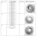
- FIG. 16 shows the internal configuration and appearance of the patches W1-W3 according to the embodiment of the present invention.
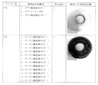
- FIG. 17 shows the internal configuration and appearance of the patch W4-W5 according to the embodiment of the present invention.
- FIG. 18 shows the internal configuration and appearance of the patch W6-W7 according to the embodiment of the present invention.
- FIG. 19 is a top view showing an example of an FRP plate with holes.
- FIG. 20 shows an example of an FRP plate with holes for artificial cracks, (a) is a top view, (b) is an enlarged view of the cracked portion, and (c) shows the depth of the artificial cracked portion in the cross section of A1-C1-B1. It is explanatory drawing.
- FIG. 21 is a configuration diagram of a test piece in which an emblem is attached to an FRP plate with artificial crack holes for an accelerated cracking test.
- FIG. 21 is a configuration diagram of a test piece in which an emblem is attached to an FRP plate with artificial crack holes for an accelerated cracking test.
- FIG. 22 is a configuration diagram showing the structure of a crack growth acceleration test facility by bolt tightening.
- FIG. 23 is a verification result of the crack growth prevention effect of the emblem according to the embodiment of the present invention.
- FIG. 24 is an explanatory diagram showing radial cracks generated by the crack growth acceleration test.
- the FRP molded body is often used by connecting the FRP molded bodies to each other or to other materials. Also, the shape is often complicated depending on the application. For example, there are some that are used under stress due to their complicated structure such as a tightening part with bolts and nuts or rivets.
- FIG. 1 is a crack model diagram of the surface of an FRP molded body having holes for bolts.
- the surface crack is expected to be a radial crack extending radially from the hole 3 of the FRP molded body 1 in the radial direction thereof.
- FIG. 2 shows a design example of a typical emblem in which a resin is impregnated by changing the fiber composition in order to prevent the growth of radial cracks.
- the material of the fiber is glass or carbon fiber or aramid fiber.
- the designed pattern is as follows.
- Patch 4 (swirl, no holes) 5 Patch 5 (swirl, with holes) 7 Patch 7 (fiber cloth, no holes) 8 Patch 8 (fiber cloth, with holes) 9 Patch 9 (fiber cloth, fiber cloth 45 degrees, no holes) 10 Patch 10 (fiber cloth, fiber cloth 45 degrees, with holes) 11 Patch 11 (fiber cloth, swirl, fiber cloth 45 degrees, no holes) 12 Patch 12 (fiber cloth, swirl, fiber cloth 45 degrees, with holes) 13 Patch 13 (half-split material of patch 11)
- the "fiber cloth 45 degrees" of the patches 9 to 12 means a fiber cloth rotated by 45 degrees with respect to the "fiber cloth” about the center of the patch.
- the emblem can be used by laminating one or more emblems and connecting them to the FRP molded body 1 with an adhesive or the like. Further, as will be described later, it is also possible to use an integrated irregularly shaped patch in which two disc-shaped patches having excellent shear strength, which are further enhanced in the strength performance of the patch which has evolved the performance of the patch, are stacked.
- FIG. 3 has a structure in which an emblem 12 is used.
- a composite type three-layer perforated patch in which a spiral glass fiber is woven vertically and horizontally and a fiber cloth is sandwiched between a fiber cloth rotated 45 degrees around the center of a hole and impregnated with resin.
- Bolt tightening is performed together with the nut 17 installed on the metal structural material 19.
- This is an example of this structure in which a bolt appears on the FRP molded body 1.
- the metal structure material 19 iron-based materials, ferrite-based stainless steel materials, austenitic stainless steel materials, aluminum alloy-based materials, and magnesium alloy-based materials can be adopted. In order to prevent corrosion of the metal-organic framework material 19, it may be sealed with the resin 14 as designed.
- the spiral glass fiber is formed by spirally winding a fiber made of untwisted glass roving in which strands are aligned with a radius larger than the diameter of a bolt hole or a rivet hole.
- the glass fiber cloth is a plain weave of yarn in which a plurality of single yarns twisted on a strand are aligned. Both are used as reinforcing materials for composite materials such as plastics.
- the count ER2310 specified in JIS3410 was used, and as the glass fiber cloth, the count 200 specified in JISR3416 was used.
- FIG. 4 is an example of a structure in which bolts do not appear on the FRP molded body 1 using the emblem 12. Bolt tightening is performed together with the nut 17 installed on the metal structural material 19. By smoothing the surface of the FRP molded product, it is intended to suppress the turbulence of the liquid phase or the gas phase. In the following designs, the surface smoothing technology is easy to use from the viewpoint of preventing scratches and the like.
- FIG. 5 is a design example in which two patches 12 are used on the front and back surfaces of the joint portion in order to join the two FRP molded bodies 1.
- Bolt tightening is done by connecting the bolt 15 and the nut 17.
- FIG. 6 is a design example in which two types of FRP molded bodies 1 having different shapes are combined. This is a design example using the emblem 4, the emblem 5, and the emblem 12. The design is such that the bolt 15 and the nut 17 are connected. The head of the metal bolt is located in the FRP recess.
- FIG. 7 shows an example in which (a) resin or (b) emblem is inserted and pasted in the recessed FRP.
- FIG. 7A is a design example in which two types of FRP molded bodies 1 having different shapes are combined, and an example in which the resin 14 is arranged in the recess and the surface of the FRP molded body is designed to be smooth.
- the structure is such that the patch 4, the patch 5, and the patch 12 are used. It is connected by a bolt 15 and a nut 17.
- FIG. 7B is a design example in which two types of FRP molded bodies 1 having different shapes are combined, and an example in which the emblem 11, the emblem 5, and the emblem 12 are arranged in the recess and the surface of the FRP molded body is designed to be smooth. Is.
- the structure is such that the emblem 11, the emblem 5, and the emblem 12 are used. It is connected by a bolt 15 and a nut 17.
- FIG. 8 is a design example in which the emblem 12 is used when the FRP molding 1 is convex in design.
- FIG. 9 is an example of applying the emblem to the case where the FRP molding 1 has a partially dented structure, and is a design example of the emblem 13 which is a half of the emblem 11.
- FIG. 10 is a design example to which the emblem 11 is applied. This is a design example in which an emblem 11 having no holes is used in order to suppress radial cracks when the FRP molding 1 has partial cracks.
- FIG. 11 is an example in which two FRP molded bodies are connected.
- the integrated first irregular shape patch 120 in which two perforated disk-shaped patches are stacked. Since a part of the integrated deformed patch is embedded in the main body of the FRP molded body 1, it has a structure showing strong resistance to shearing force.
- FIG. 12 is an example in which two FRP molded bodies are connected.
- it is a design example using the integrated first irregularly shaped patch 120 in which two perforated disk-shaped patches are stacked, and the structure is such that the bolt does not come out from the surface.
- FIG. 13 is an example in which two FRP molded bodies are connected.
- this is a design example using the integrated first irregularly shaped patch 120 in which two disk-shaped patches in the shape of two perforated disks are stacked.
- patches are arranged on the front and back, and the structure is more reinforced.
- FIG. 14 is a design example of a bolt tightening structure connected to the metal structural material 19.
- the integrated second irregular shape patch 130 having a shape in which three perforated disks are stacked in order to increase the shear strength of the patch.
- the integrated irregularly shaped patch used here can be manufactured by the manufacturing method described in this patent. It is possible to manufacture a reinforced FRP by the FRP vacuum forming manufacturing method (VPI manufacturing method), which is pre-installed inside the molded body, using the manufactured integrated irregularly shaped patch.
- This usage is an integrated second variant in which three disc-shaped patches made of soft resin such as poipene and nylon are stacked, even if the patch is not made of FRP because the structure around the hole is constrained.
- An emblem may be used.
- the shape is adjusted by cutting so that the bolt hole is penetrated, and then the FRP including the bolt portion is formed.
- a connection structure to which a reinforcing member is attached may be produced.
- the molded patches can be glued together to form a composite.
- An emblem composite may be produced and used by attaching an adhesive to each of the patches. Considering industrial use, it is desirable to use a patch having a different shape, which is formed by stacking two disk-shaped patches and integrally molding them, because it is easy to use.
- Instant adhesives, epoxy adhesives or acrylic adhesives can be used for strong adhesion of these members.
- Instant adhesives, epoxy or acrylic adhesives can also be used to bond between patches. Further, a strong adhesive double-sided tape may be used.
- FIG. 15 shows an example of press molding and taking out of an emblem in the method for producing an emblem of the present invention.
- 20 is an upper die for pressing a material (fiber cloth made of resin and glass fiber or carbon fiber) 23
- 21 is a lower die
- 22 is an axial alignment hole.
- reference numeral 12 denotes an emblem taken out from the mold after press working.
- the manufacturing method of the emblem will be described. First, polypropylene and glass fiber or carbon fiber are used, and they are put into the lower mold 21 in order.
- a reinforcing material made of polypropylene and glass fiber or carbon fiber is arranged in a predetermined combination so as to have the designed structure, and the stress is 1.7 kgf / mm 2 (load 907 kgf / 530 mm 2 ) at 230 ° C. After pressing and holding for 15 minutes, the load stress is removed, and then, for example, an emblem 12 having a size of about 5 mm manufactured by cooling is demolded.
- FIG. 16 shows the internal configuration and appearance of the 5 mm-thick emblem, which is an invention. It was possible to produce a practical patch without defects such as holes in all of the patches W1 to W3.
- the emblem W1 can be manufactured from eight glass fiber cloths (0 °) (0 °: fiber cloth rotation angle 0 °) and polypropylene. Each glass fiber cloth to be laminated is not rotated.
- the emblem W2 is composed of eight glass fiber cloths (0 °) shifted by 45 degrees (45 °) (45 °: fiber cloth rotation angle 45 °), and is made of these glass fiber cloth and polypropylene. It shows the emblem.
- the emblem W3 shows an emblem made of a glass fiber cloth (0 °), a spiral glass fiber using a glass roving material, a glass fiber cloth (0 °), and polypropylene.
- FIG. 17 shows the internal configuration and appearance of the 5 mm-thick emblem, which is an invention.
- the emblem W4 shows an emblem made of a glass fiber cloth (0 °), a spiral glass fiber using a glass roving material, a glass fiber cloth (45 °), and polypropylene.
- the emblem W5 is composed of 13 carbon fiber woven fabrics (0 °) shifted by 45 degrees (45 °) (45 °: fiber cloth rotation angle 45 °), and these carbon fiber woven fabrics. It shows an emblem made of fiber cloth and polypropylene.
- FIG. 18 has the same structure as the internal structure of the 5 mm-thick emblem W4, which is an invention, and in order to investigate the effect of the thickness, 2 mm W6 and 3 mm W7 inventions were manufactured and their external photographs are shown. It is a thing. We were able to manufacture patches that are free of defects such as practical vacancies across all patches W6 to W7.
- FIGS. 19 to 22 show diagrams for explaining a test in which a crack generation acceleration test was performed under a condition of large bending strain using a sample in which artificial cracks were formed in the produced patch.
- FIG. 19 is an FRP plate with a hole having a thickness of 3 mm. The diameter of the central hole is 17 mm.
- FIG. 20 shows an FRP plate with artificial cracked holes. Assuming that micro cracks were present during hole drilling, artificial cracks (length 1.5 mm) were applied to the notches in the holes, and a crack acceleration test was conducted.
- FIG. 20A is an overall view of an FRP plate with artificial cracked holes.
- 20 (b) is an enlarged view of the artificial cracked portion of FIG. 20 (a), which is an enlarged view of the cracked portion 24.
- FIG. 20 (c) shows the cross section of the artificial crack when cut in the cross section of A1-C1-B1 in the enlarged view of FIG. 20 (b), and the artificial crack shape is substantially triangular.
- C1 is the tip position of the artificial crack.
- FIG. 21 is a block diagram of a test piece in which an emblem is attached to an FRP plate with holes (with artificial cracks in the figure).
- a commercially available adhesive under the trade name "grasp-neo" was used to bond the patch and the FRP plate.
- FIG. 22 shows an equipment structure for performing a crack generation acceleration test by bolt tightening, and shows a jig for a bolt tightening evaluation test and a tightening state.
- the cracking acceleration test was performed as follows. Gradually tighten the hexagon bolt and apply a load continuously up to 10 Nm with a torque wrench. This load was constant in all tests. Rotation speed: about 4 rps.
- FIG. 23 shows the verification result of the crack prevention effect of the invention patch. This is a summary of the evaluation results of the crack progress suppressing effect of the crack prevention patch.
- a test was conducted using an FRP plate with holes with artificial cracks without attaching an emblem.
- FIG. 24 in the FRP molded body 1 without an emblem shown as a comparative product, it can be seen that radial cracks 23 are generated from the vicinity of the artificial cracks 24 around the FRP holes.
- the FRP reinforcing member and its manufacturing method, the FRP molded body and the FRP connection structure of the present invention are members for lightweight small airplanes, air conditioning equipment, industrial / nursing robots, trucks, passenger cars, train parts, installations for wind power generation, etc. It can be applied to housings for medical equipment, large drones, and other FRP housings and FRP parts.
Landscapes
- Engineering & Computer Science (AREA)
- Mechanical Engineering (AREA)
- Chemical & Material Sciences (AREA)
- Composite Materials (AREA)
- Textile Engineering (AREA)
- Crystallography & Structural Chemistry (AREA)
- Inorganic Chemistry (AREA)
- Laminated Bodies (AREA)
- Moulding By Coating Moulds (AREA)
- Connection Of Plates (AREA)
Priority Applications (5)
| Application Number | Priority Date | Filing Date | Title |
|---|---|---|---|
| CN202180025481.XA CN115427220B (zh) | 2020-03-30 | 2021-03-29 | Frp加强用部件及其制造方法、frp成型体和frp连接结构体 |
| JP2022511170A JP7190087B2 (ja) | 2020-03-30 | 2021-03-29 | Frp補強用部材及びその製造方法、frp成形体並びにfrp接続構造体 |
| US17/915,963 US20230114819A1 (en) | 2020-03-30 | 2021-03-29 | Frp reinforcing member, method method for producing the same, frp molded body, and frp connection structure |
| EP21781761.8A EP4129637A4 (en) | 2020-03-30 | 2021-03-29 | FRP REINFORCEMENT ELEMENT, METHOD OF MANUFACTURING THE SAME, FRP MOLDED BODY AND FRP JOINT STRUCTURE |
| JP2022173792A JP7458566B2 (ja) | 2020-03-30 | 2022-10-12 | Frp補強用部材及びその製造方法、frp成形体並びにfrp接続構造体 |
Applications Claiming Priority (2)
| Application Number | Priority Date | Filing Date | Title |
|---|---|---|---|
| JP2020073119 | 2020-03-30 | ||
| JP2020-073119 | 2020-03-30 |
Publications (1)
| Publication Number | Publication Date |
|---|---|
| WO2021201298A1 true WO2021201298A1 (ja) | 2021-10-07 |
Family
ID=77930377
Family Applications (1)
| Application Number | Title | Priority Date | Filing Date |
|---|---|---|---|
| PCT/JP2021/014684 Ceased WO2021201298A1 (ja) | 2020-03-30 | 2021-03-29 | Frp補強用部材及びその製造方法、frp成形体並びにfrp接続構造体 |
Country Status (4)
| Country | Link |
|---|---|
| US (1) | US20230114819A1 (https=) |
| EP (1) | EP4129637A4 (https=) |
| JP (2) | JP7190087B2 (https=) |
| WO (1) | WO2021201298A1 (https=) |
Cited By (2)
| Publication number | Priority date | Publication date | Assignee | Title |
|---|---|---|---|---|
| US20210178460A1 (en) * | 2013-06-28 | 2021-06-17 | Danieli & C. Officine Meccaniche S.P.A. | Crystallizer for continuous casting and method for its production |
| CN115742103A (zh) * | 2022-10-14 | 2023-03-07 | 佛山市南海汗高轨道交通设备有限公司 | 一种玻璃钢制备模具及制备玻璃钢的方法 |
Families Citing this family (3)
| Publication number | Priority date | Publication date | Assignee | Title |
|---|---|---|---|---|
| EP4210934A1 (en) * | 2020-09-14 | 2023-07-19 | Aalborg Universitet | Method of manufacturing a fibre reinforced composite component having a reinforced hole |
| JP2025110855A (ja) * | 2024-01-16 | 2025-07-29 | 株式会社ジェイ・オー・エヌ・七二 | Frp成形体の接合構造及びその製造方法 |
| WO2026058479A1 (ja) * | 2024-09-12 | 2026-03-19 | 帝人株式会社 | 接合構造体および接合構造体の製造方法 |
Citations (6)
| Publication number | Priority date | Publication date | Assignee | Title |
|---|---|---|---|---|
| JPS60131710U (ja) * | 1984-02-13 | 1985-09-03 | 三菱電機株式会社 | 強化プラスチツク板状体の締結構造 |
| JPS62179408U (https=) * | 1986-05-07 | 1987-11-14 | ||
| JP2002361666A (ja) * | 2001-06-04 | 2002-12-18 | Toyota Motor Corp | Frp積層体及びfrpの成形方法 |
| JP2009292054A (ja) * | 2008-06-05 | 2009-12-17 | Motoyasu Hibi | 繊維強化プラスチックのプレス成形法 |
| JP2012035442A (ja) * | 2010-08-04 | 2012-02-23 | Toyota Motor Corp | 繊維強化樹脂部材及び締結構造 |
| JP2013208861A (ja) * | 2012-03-30 | 2013-10-10 | Hiroshima Prefecture | 繊維強化樹脂材料部材の締結構造 |
Family Cites Families (10)
| Publication number | Priority date | Publication date | Assignee | Title |
|---|---|---|---|---|
| JPS5871151A (ja) * | 1981-10-23 | 1983-04-27 | 川崎重工業株式会社 | 複合材製品のフアスナ−継手構造 |
| JPH0854013A (ja) * | 1994-08-10 | 1996-02-27 | Taihei Kk | Frp製座金とその製造方法 |
| JP2003225914A (ja) | 2002-01-31 | 2003-08-12 | Mitsubishi Electric Corp | 繊維体補強樹脂成形品 |
| CN101043954B (zh) * | 2004-08-31 | 2012-11-21 | 亨利K·奥柏梅尔 | 纤维增强复合材料的高强度连接系统 |
| JP4990087B2 (ja) | 2007-10-05 | 2012-08-01 | 株式会社熊谷組 | 建築物の孔補強構造及び孔補強方法 |
| JP6212129B2 (ja) * | 2012-11-26 | 2017-10-11 | サイテク・インダストリーズ・インコーポレーテツド | 複合材料の結合 |
| US9505489B2 (en) * | 2013-03-13 | 2016-11-29 | Bell Helicopter Textron Inc. | Flexing clevis arrangement bolted joint attachment for flexible rotor hub with high offset and high flapping |
| JP2018020747A (ja) | 2016-08-05 | 2018-02-08 | トヨタ自動車株式会社 | 車両用骨格部材 |
| GB2559403B (en) * | 2017-02-06 | 2022-06-01 | Short Brothers Plc | Aircraft electrical isolation component and method of manufacturing electrical isolation component |
| JP6751835B2 (ja) | 2018-11-30 | 2020-09-09 | 株式会社北陸カラーフオーム | 繊維強化樹脂構造体の製造方法 |
-
2021
- 2021-03-29 JP JP2022511170A patent/JP7190087B2/ja active Active
- 2021-03-29 US US17/915,963 patent/US20230114819A1/en active Pending
- 2021-03-29 EP EP21781761.8A patent/EP4129637A4/en active Pending
- 2021-03-29 WO PCT/JP2021/014684 patent/WO2021201298A1/ja not_active Ceased
-
2022
- 2022-10-12 JP JP2022173792A patent/JP7458566B2/ja active Active
Patent Citations (6)
| Publication number | Priority date | Publication date | Assignee | Title |
|---|---|---|---|---|
| JPS60131710U (ja) * | 1984-02-13 | 1985-09-03 | 三菱電機株式会社 | 強化プラスチツク板状体の締結構造 |
| JPS62179408U (https=) * | 1986-05-07 | 1987-11-14 | ||
| JP2002361666A (ja) * | 2001-06-04 | 2002-12-18 | Toyota Motor Corp | Frp積層体及びfrpの成形方法 |
| JP2009292054A (ja) * | 2008-06-05 | 2009-12-17 | Motoyasu Hibi | 繊維強化プラスチックのプレス成形法 |
| JP2012035442A (ja) * | 2010-08-04 | 2012-02-23 | Toyota Motor Corp | 繊維強化樹脂部材及び締結構造 |
| JP2013208861A (ja) * | 2012-03-30 | 2013-10-10 | Hiroshima Prefecture | 繊維強化樹脂材料部材の締結構造 |
Non-Patent Citations (1)
| Title |
|---|
| "FRP Molding Skills Textbook", THE JAPAN REINFORCED PLASTICS SOCIETY, 31 October 1997 (1997-10-31) |
Cited By (2)
| Publication number | Priority date | Publication date | Assignee | Title |
|---|---|---|---|---|
| US20210178460A1 (en) * | 2013-06-28 | 2021-06-17 | Danieli & C. Officine Meccaniche S.P.A. | Crystallizer for continuous casting and method for its production |
| CN115742103A (zh) * | 2022-10-14 | 2023-03-07 | 佛山市南海汗高轨道交通设备有限公司 | 一种玻璃钢制备模具及制备玻璃钢的方法 |
Also Published As
| Publication number | Publication date |
|---|---|
| JPWO2021201298A1 (https=) | 2021-10-07 |
| JP2023010739A (ja) | 2023-01-20 |
| JP7458566B2 (ja) | 2024-04-01 |
| EP4129637A4 (en) | 2024-12-18 |
| US20230114819A1 (en) | 2023-04-13 |
| CN115427220A (zh) | 2022-12-02 |
| EP4129637A1 (en) | 2023-02-08 |
| JP7190087B2 (ja) | 2022-12-15 |
Similar Documents
| Publication | Publication Date | Title |
|---|---|---|
| JP7190087B2 (ja) | Frp補強用部材及びその製造方法、frp成形体並びにfrp接続構造体 | |
| EP2605902B1 (en) | Composite structures having composite-to-metal joints and method for making the same | |
| CN1950200B (zh) | 铝-纤维层压体 | |
| JP4126978B2 (ja) | プリフォームおよびそれからなるfrpならびにfrpの製造方法 | |
| US10112373B2 (en) | Multi-layer metallic structure and composite-to-metal joint methods | |
| JP5852887B2 (ja) | 適合させたパッチを用いた複合構造の予測可能な結合補修 | |
| EP2014437A1 (en) | Method of molding composite-material-made structural member and composite-material-made structural member | |
| NZ548594A (en) | High impact strength, elastic, composite, fibre, metal laminate | |
| Khan et al. | Effect of various surface preparation techniques on the delamination properties of vacuum infused Carbon fiber reinforced aluminum laminates (CARALL): Experimentation and numerical simulation | |
| JP2016064646A (ja) | 補強プレート間の複合材梁弦材、及び関連する製造方法 | |
| Valenza et al. | Mechanical behaviour and failure modes of metal to composite adhesive joints for nautical applications | |
| EP2650120A2 (en) | Multi-layer metallic structure and composite-to-metal joint methods | |
| US20230415448A1 (en) | Honeycomb core sandwich panels | |
| WO2005049933A1 (en) | Sandwich panel and a method of producing a sandwich panel | |
| JP2944967B2 (ja) | 高速車両の外壁構造および高速車両の外壁の製造方法 | |
| Sam-Daliri et al. | Mechanical analysis of unidirectional glass fibre reinforced epoxy composite joints manufactured by adhesive bonding and co-curing techniques | |
| Palkowski et al. | Metal-polymer-metal laminates for lightweight application | |
| CN115427220B (zh) | Frp加强用部件及其制造方法、frp成型体和frp连接结构体 | |
| JP2002361666A (ja) | Frp積層体及びfrpの成形方法 | |
| CN116882069B (zh) | 轨道车辆复合材料扶手杆设计方法、扶手及轨道车辆 | |
| JP2023145292A (ja) | 成形体補強用部材、これを用いた成形体並びに接続構造体 | |
| CN110561765A (zh) | 一种大尺寸复合材料制件的连接方法 | |
| JP6854045B2 (ja) | 継手構造の製造方法 | |
| JP2024006835A (ja) | Frp補強用部材、frp接続構造体及びfrp成形体 | |
| WO2019219662A1 (en) | Composite joint |
Legal Events
| Date | Code | Title | Description |
|---|---|---|---|
| 121 | Ep: the epo has been informed by wipo that ep was designated in this application |
Ref document number: 21781761 Country of ref document: EP Kind code of ref document: A1 |
|
| ENP | Entry into the national phase |
Ref document number: 2022511170 Country of ref document: JP Kind code of ref document: A |
|
| NENP | Non-entry into the national phase |
Ref country code: DE |
|
| ENP | Entry into the national phase |
Ref document number: 2021781761 Country of ref document: EP Effective date: 20221031 |