WO2021200356A1 - 接触子ユニット、ソケットの集合体、及びコネクタ - Google Patents
接触子ユニット、ソケットの集合体、及びコネクタ Download PDFInfo
- Publication number
- WO2021200356A1 WO2021200356A1 PCT/JP2021/011829 JP2021011829W WO2021200356A1 WO 2021200356 A1 WO2021200356 A1 WO 2021200356A1 JP 2021011829 W JP2021011829 W JP 2021011829W WO 2021200356 A1 WO2021200356 A1 WO 2021200356A1
- Authority
- WO
- WIPO (PCT)
- Prior art keywords
- socket
- hole
- sockets
- protruding portion
- holding member
- Prior art date
- Legal status (The legal status is an assumption and is not a legal conclusion. Google has not performed a legal analysis and makes no representation as to the accuracy of the status listed.)
- Ceased
Links
Images







Classifications
-
- G—PHYSICS
- G01—MEASURING; TESTING
- G01R—MEASURING ELECTRIC VARIABLES; MEASURING MAGNETIC VARIABLES
- G01R1/00—Details of instruments or arrangements of the types included in groups G01R5/00 - G01R13/00 and G01R31/00
- G01R1/02—General constructional details
- G01R1/06—Measuring leads; Measuring probes
- G01R1/067—Measuring probes
-
- G—PHYSICS
- G01—MEASURING; TESTING
- G01R—MEASURING ELECTRIC VARIABLES; MEASURING MAGNETIC VARIABLES
- G01R1/00—Details of instruments or arrangements of the types included in groups G01R5/00 - G01R13/00 and G01R31/00
- G01R1/02—General constructional details
- G01R1/06—Measuring leads; Measuring probes
- G01R1/067—Measuring probes
- G01R1/073—Multiple probes
-
- H—ELECTRICITY
- H01—ELECTRIC ELEMENTS
- H01R—ELECTRICALLY-CONDUCTIVE CONNECTIONS; STRUCTURAL ASSOCIATIONS OF A PLURALITY OF MUTUALLY-INSULATED ELECTRICAL CONNECTING ELEMENTS; COUPLING DEVICES; CURRENT COLLECTORS
- H01R13/00—Details of coupling devices of the kinds covered by groups H01R12/70 or H01R24/00 - H01R33/00
- H01R13/02—Contact members
- H01R13/10—Sockets for co-operation with pins or blades
-
- H—ELECTRICITY
- H01—ELECTRIC ELEMENTS
- H01R—ELECTRICALLY-CONDUCTIVE CONNECTIONS; STRUCTURAL ASSOCIATIONS OF A PLURALITY OF MUTUALLY-INSULATED ELECTRICAL CONNECTING ELEMENTS; COUPLING DEVICES; CURRENT COLLECTORS
- H01R13/00—Details of coupling devices of the kinds covered by groups H01R12/70 or H01R24/00 - H01R33/00
- H01R13/02—Contact members
- H01R13/22—Contacts for co-operating by abutting
- H01R13/24—Contacts for co-operating by abutting resilient; resiliently-mounted
-
- H—ELECTRICITY
- H01—ELECTRIC ELEMENTS
- H01R—ELECTRICALLY-CONDUCTIVE CONNECTIONS; STRUCTURAL ASSOCIATIONS OF A PLURALITY OF MUTUALLY-INSULATED ELECTRICAL CONNECTING ELEMENTS; COUPLING DEVICES; CURRENT COLLECTORS
- H01R33/00—Coupling devices specially adapted for supporting apparatus and having one part acting as a holder providing support and electrical connection via a counterpart which is structurally associated with the apparatus, e.g. lamp holders; Separate parts thereof
- H01R33/74—Devices having four or more poles, e.g. holders for compact fluorescent lamps
- H01R33/76—Holders with sockets, clips, or analogous contacts adapted for axially-sliding engagement with parallely-arranged pins, blades, or analogous contacts on counterpart, e.g. electronic tube socket
Definitions
- the present invention relates to a contactor unit, an assembly of sockets constituting the contactor unit, and a connector including the contactor unit.
- Japanese Patent Application Laid-Open No. 2008-98090 discloses a multi-pole connector in which a plurality of first terminals and second terminals are conductively connected to each other.
- This multi-pole connector has a cylinder body formed in an elongated cylindrical shape, a contactor housed inside the cylinder body and in a conductive state with the cylinder body, and a holding body for holding the cylinder body.
- a cylinder body (socket) for holding a contact is fitted in a hole formed in a holder (holding member). It is held in a state.
- the cylinder body of the contactor is held by the holding body according to the frictional force acting by being pressed against the peripheral surface of the hole of the holding body. There was room for further improvement in this holding power.
- An object of the present invention is to provide a contact unit, an assembly of sockets, and a connector capable of reducing the possibility that the contact unit will come out of the holding member.
- the contactor unit is a contactor unit that is inserted and held in an accommodating hole provided in a holding member and a hole provided in a cover member attached to the holding member.
- a cylindrical socket having a socket body inserted into the accommodating hole, a tip-side portion inserted into the hole, and an intermediate portion provided between the socket body and the tip-side portion. It is provided with a contactor held by a socket, the intermediate portion is provided with a protruding portion that protrudes radially outward from the peripheral surface thereof, and the outer edge of the protruding portion on the socket body side is the socket.
- the aggregate of sockets is an aggregate of the sockets constituting the contactor unit described above, and a plurality of accommodating holes are provided, and a carrier for transporting the sockets and the above.
- the carrier is provided with a plurality of the sockets to be conveyed together with the carrier, and the carrier is provided with a plurality of connecting portions in which the axial end portions of the sockets are detachably connected to each other at regular intervals.
- the connector according to an example of the present invention includes the above-mentioned contact unit, the holding member, and the cover member, and a receiving portion that receives the protruding portion between the holding member and the cover member. Is formed, the radius of the hole of the cover member is shorter than the radial distance from the axis to the top of the protrusion, and the radius of the accommodating hole of the holding member is from the axis to the apex. Shorter than the radial distance to the top of the protrusion.
- the contact unit, the assembly of sockets, and the connector having such a configuration can reduce the possibility that the contact unit will come out of the holding member.
- FIG. 1 is a partial cross-sectional view of a multi-pole connector according to an embodiment of the present invention.
- FIG. 2 is a cross-sectional view showing a specific configuration of the contactor.
- FIG. 3 is an exploded front view of the contactor unit according to the embodiment of the present invention.
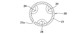
- FIG. 4 is a sectional view taken along line IV-IV of FIG.
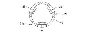
- FIG. 5 is a sectional view taken along line VV of FIG.
- FIG. 6 is a sectional view taken along line VI-VI of FIG.
- FIG. 7 is a sectional view taken along line VII-VII of FIG.
- FIG. 8 is a sectional view taken along line VIII-VIII of FIG.
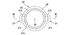
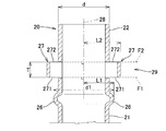
- FIG. 9 is a cross-sectional view taken along the line IX-IX of FIG.
- FIG. 1 is a partial cross-sectional view of a multi-pole connector according to an embodiment of the present invention.
- FIG. 2 is a cross-sectional view showing a specific configuration of the contactor
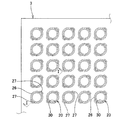
- FIG. 10 is a plan view showing a state in which the socket is accommodated in a part of the accommodating holes.
- FIG. 11 is a front view showing the configuration of an aggregate of sockets.
- FIG. 12 is a cross-sectional view taken along the line XII-XII of FIG.
- FIG. 13 is a front view showing a manufacturing process of an assembly of sockets.
- FIG. 14 is a cross-sectional view showing a housing state of the socket.
- FIG. 15 is a plan view showing a state in which sockets are accommodated in all the accommodating holes.
- FIG. 16 is a plan sectional view showing a modified example of the assembly of sockets.
- FIG. 17 is a plan view showing a state in which the socket is accommodated in a part of the accommodating holes.
- FIG. 18 is a partial cross-sectional view showing a modified example of the protruding portion shown in FIG. 7.
- FIG. 19 is a front view of the protruding portion shown in FIG.
- FIG. 20 is a partial cross-sectional view showing a modified example of the multi-pole connector shown in FIG.
- each part of the multi-pole connector 1 shown in each figure is schematically shown.
- the multi-pole connector 1 corresponds to an example of a connector according to the present invention.
- FIG. 1 shows a cross-sectional view taken along the line II of FIG.
- the vertical direction in each drawing is defined with reference to the longitudinal direction of the contactor unit 2, and the upper side of each drawing is the tip end side in the longitudinal direction of the contactor unit 2, and the lower side of each drawing. The side is the base end side in the longitudinal direction of the contactor unit 2.
- the multi-pole connector 1 shown in FIG. 1 electrically connects a plurality of first terminals A and a plurality of second terminals B.
- the first terminal A of the connection switching unit (not shown) which is the first connection target is connected to the base end portion of the multi-pole connector 1 and is used for the inspection jig which is the second connection target.
- the second terminal B of the connector (not shown) is connected to the tip of the multi-pole connector 1.
- the first terminal A and the second terminal B are electrically connected to each other via the contact unit 2 provided on the multi-pole connector 1.
- the connection switching unit consists of, for example, a so-called scanner device used in a board inspection device for inspecting the electrical characteristics of a wiring pattern provided on a board.
- This scanner device is located between an inspection unit provided with a power supply unit, a voltage detection unit, and a current detection unit for inspection of the main body of the inspection device and a contact provided on a connector for an inspection jig which is a second connection target. It switches the electrical connection relationship of.
- connection switching unit for example, a plurality of first terminals A composed of electrode pins and the like connected to a plurality of switching elements are arranged at a predetermined pitch. Then, a plurality of first terminals A are projected from the connection switching unit arranged on the lower side of FIG. 1 toward the base end side of the multi-pole connector 1.
- a plurality of second terminals B composed of electrode pins and the like are arranged at a predetermined pitch in the inspection jig connector.
- the second terminal B is connected to each contactor of the inspection jig, which is pressed against an inspection point such as a wiring pattern to be inspected, via a conducting wire. Then, a plurality of second terminals B are projected from the inspection jig connector arranged on the upper side of FIG. 1 toward the tip end side of the multi-pole connector 1.
- the multi-pole connector 1 is not limited to a relay between the connection switching unit and the inspection jig connector, and can be applied to various other uses. That is, the connection target connected to the base end portion of the multi-pole connector 1 is not limited to the first terminal A provided in the connection switching unit. Further, the connection target connected to the tip of the multi-pole connector 1 is not limited to the second terminal B provided in the inspection jig connector.
- the multi-pole connector 1 includes a plurality of contactor units 2 having contacts 10, a base plate 3 which is an example of a holding member, and a cover plate 4 which is an example of a cover member.
- the connector is not limited to the case where a plurality of contactor units 2 are provided, and the connector may be provided with only one contactor unit 2.
- the base plate 3 is formed with a plurality of circular accommodating holes 30 that penetrate the base plate 3 in the thickness direction.
- the cover plate 4 is formed with a plurality of circular holes 50 that penetrate the cover plate 4 in the thickness direction.
- the diameters of the accommodating hole 30 and the hole 50 are both set to the inner diameter D.
- the contactor 10 is arranged in a tubular body 11 formed in a substantially cylindrical shape by a conductive member, a plunger 12 formed in a rod shape by a conductive member, and a tubular body 11.
- the coil spring 13 is provided.
- a cup 13 having a diameter larger than that of the plunger 12 is provided at the tip of the plunger 12.
- a funnel portion 13a recessed in a funnel shape is formed at the tip of the cup 13.
- the cup 13 has a larger diameter than the second terminal B.
- the cup 13 is not limited to the case where the cup 13 is provided at the tip of the plunger 12.
- the tip of the plunger 12 may have a substantially conical pointed shape as in the plunger 12a shown in FIG. 20, or a so-called crown shape having a plurality of protrusions as in the plunger 12b. May be good.
- the tip of the plunger 12 may have various shapes that can be easily contacted with the second terminal B.
- a tip opening 11a is formed at the tip of the tubular body 11 located on the upper side of FIG.
- a bottom wall 11b having a base end opening 11c is provided at the base end portion of the tubular body 11 located on the lower side of FIG.
- the base end side of the plunger 12 is configured to be insertable into the tubular body 11 from the tip opening 11a.
- An axially intermediate portion of the tubular body 11 is provided with a reduced diameter portion 11d that is deformed so as to dent a part of the tubular body 11 inward.
- a bulging portion 121 having an outer diameter slightly larger than the inner diameter of the reduced diameter portion 11d of the tubular body 11 is provided at the base end portion of the plunger 12.
- the bulging portion 121 is inserted into the tubular body 11 and pushed toward the base end portion side of the reduced diameter portion 11d.
- the plunger 12 is slidably supported by the tubular body 11 in a state where the plunger 12 is prevented from coming out to the upper side of the tubular body 11.
- the outer diameter of the coil spring 13 is formed to be slightly smaller than the inner diameter of the tubular body 11 and larger than the inner diameter of the base end opening 11c of the tubular body 11.
- the coil spring 13 is arranged between the bulging portion 121 of the plunger 12 and the bottom wall 11b of the tubular body 11 to urge the bulging portion 121 upward.
- the contact unit 2 has a socket 20 formed in a cylindrical shape by a conductive metal material.
- the inner diameter of the socket 20 is formed to be slightly larger than the outer diameter of the contacter 10. Then, a base end side portion of the contactor 10, specifically, a lower portion of the tubular body 11 is inserted into the socket 20 and is held.
- a slit portion 21a extending in the longitudinal direction of the socket 20 is formed on the peripheral wall of the socket 20.
- the slit portion 21a is a gap that is inevitably formed in the peripheral wall of the socket 20 when the rectangular socket component is curved into a cylindrical shape to form the socket 20, as will be described later.
- the socket 20 is provided between the socket body 21 inserted into the accommodating hole 30 of the base plate 3, the tip side portion 22 inserted into the hole 50 of the cover plate 4, and the socket body 21 and the tip side portion 22. It has an intermediate portion 29 and the like.
- the first terminal spring 23, the contact stopper 24, the contact spring 25, and the bulging portion 26 are located at the lower end of the socket body 21 in FIG. It is provided in order from the part side.
- the first terminal spring 23 is a cantilever-shaped leaf spring material formed by bending the upper portion of the trapezoidal notch formed in the socket main body 21 inward of the socket main body 21.
- the contact stopper 24 is formed, for example, by recessing the lower portion of the notch 24a (see FIG. 3) extending in the circumferential direction of the socket body 21 inward in the radial direction of the socket body 21.
- three contact springs 25 are provided on the upper side of the contact stopper 24 at equal intervals in the circumferential direction of the socket body 21. As shown in FIG. 3, the contact spring 25 pushes a portion located between a pair of axially extending slits 25a and 25a formed on the peripheral wall of the socket body 21 inward in the radial direction of the socket body 21. It is a leaf spring material in the shape of a double-sided beam formed by.
- the three first terminal springs 23, the contact stopper 24, and the contact spring 25 arranged at equal intervals in the circumferential direction of the socket body 21 are viewed in a plan view of the socket body 21.
- An example is shown in which they are formed at overlapping positions.
- each of the first terminal spring 23, the contact stopper 24, and the contact spring 25 may be formed at positions shifted in the circumferential direction in the plan view of the socket body 21.
- the peripheral wall of the socket main body 21 is provided in the radial direction over the entire circumference thereof.
- a ring-shaped bulging portion 26 that bulges outward is provided.
- the bulging portion 26 does not necessarily have to be formed over the entire circumference of the socket main body 21, and may be configured to include a plurality of bulging portions divided in the circumferential direction of the socket main body 21. Further, the socket 20 does not have to include the bulging portion 26.
- the intermediate portion 29 is provided with a pair of projecting portions 27 projecting outward in the radial direction.
- the protruding portion 27 is composed of a cut-up portion formed by extruding a portion sandwiched between a pair of cutting lines extending in parallel in the circumferential direction formed on the peripheral wall of the intermediate portion 29 outward in the radial direction of the intermediate portion 29. ing.
- the protruding portion 27 has an arch shape (double-sided beam shape) in which a part of the peripheral wall of the intermediate portion 29 is bridged in a direction orthogonal to the direction of the axis 28.
- the outer edge of the protrusion 27 on the socket body 21 side that is, the lower end surface 271 of the protrusion 27 is included in the virtual first plane F1 orthogonal to the axis 28. It extends horizontally from the peripheral surface of the socket 20.
- the outer edge of the protruding portion 27 on the distal end side portion 22 side that is, the upper end surface 272 of the protruding portion 27 is horizontal from the peripheral surface of the socket 20 so as to be included in the virtual second plane F2 orthogonal to the axis 28. It's growing.
- the pair of projecting portions 27 project in opposite directions with respect to the axial center 28 of the socket 20.
- the distance L2 from the axial center 28 to the tip of the protruding portion 27 is formed to be larger than the distance L1 from the axial center 28 of the socket 20 to the outer peripheral surface of the bulging portion 26.
- the base plate 3 and the cover plate 4 are formed into a rectangular plate shape having a rectangular plan view shape by an insulating member having a predetermined thickness.
- the cover plate 4 is fixed to the base plate 3 by means such as screwing.
- the base plate 3 has a facing surface FB facing the cover plate 4, and the cover plate 4 has a facing surface FC facing the base plate 3.
- the cover plate 4 is formed with a spacer portion 40 protruding from the facing surface FC.
- the facing surface FB and the facing surface FC face each other with a gap of the facing interval P.
- the facing distance P corresponds to the height of the protrusion of the spacer portion 40.
- the inner diameter D of the accommodating hole 30 is formed to be slightly larger than the outer diameter d of the socket 20 shown in FIG. 9 and slightly smaller than the outer diameter d1 of the bulging portion 26.
- the radius D / 2 of the accommodating hole 30 and the hole 50 is smaller than the distance L2 from the axial center 28 to the tip of the protruding portion 27.
- the socket 20 when the socket 20 is inserted into the accommodating hole 30, the bulging portion 26 is press-fitted into the accommodating hole 30, and the lower end surface 271 of the protruding portion 27 is abutted against the facing surface FB of the base plate 3. As a result, the socket 20 is positioned in the axial direction thereof, and the intermediate portion 29 and the tip end side portion 22 of the socket 20 are in a state of protruding from the facing surface FB.
- the bulging portion 26 When the bulging portion 26 is arranged slightly below the protruding portion 27 at a position close to the protruding portion 27, the bulging portion 26 is press-fitted immediately before the insertion operation of the socket body 21 into the accommodating hole 30 is completed. become. Therefore, as compared with the case where the bulging portion 26 is arranged at a distant position on the lower side of the protruding portion 27, the user can easily perform the operation of inserting the socket main body 21 into the accommodating hole 30.
- the lower end surface 271 of the protrusion 27 extends horizontally from the peripheral surface of the socket 20 so as to be included in the first plane F1 orthogonal to the axis 28.
- the lower end surface 271 and the facing surface FB come into surface contact in the axial direction.
- a repulsive force is applied from the facing surface FB to the lower end surface 271 along the axial direction.
- the certainty that the lower end surface 271 is pressed by the facing surface FB is improved as compared with the case where the lower end surface 271 is inclined with respect to the axial direction or the lower end surface 271 is a curved surface, for example. Therefore, the possibility that the contact unit 2 will come out of the base plate 3 is reduced.
- the tip end side portion 22 is inserted into the hole portion 50 of the cover plate 4 and held, and the protruding portion 27 is located in the gap of the facing interval P.
- the gap of the facing interval P corresponds to an example of the receiving portion.
- the radius D / 2 of the hole 50 is smaller than the distance L2 from the axis 28 to the tip of the protrusion 27, when the socket 20 tries to move above the hole 50, the protrusion 27 moves to the periphery of the hole 50. Interferes with the facing surface FC.
- the upper end surface 272 of the protruding portion 27 extends horizontally from the peripheral surface of the socket 20 so as to be included in the second plane F2 orthogonal to the axis 28, the upper end surface 272 and the facing surface FC are in contact with each other. Surface contact in the axial direction.
- a repulsive force is applied from the facing surface FC to the upper end surface 272 along the axial direction.
- the certainty that the upper end surface 272 is pressed by the facing surface FC is improved as compared with the case where the upper end surface 272 is inclined with respect to the axial direction or the upper end surface 272 is a curved surface, for example. Therefore, the possibility that the contact unit 2 will come out of the cover plate 4 is reduced.
- the axial dimension T of the socket 20 is substantially the same as or slightly smaller than the facing distance P, the axial direction is in a state where the contact unit 2 is held by the base plate 3 and the cover plate 4. The risk of misalignment along the line is reduced.
- the contact unit 2 with respect to the base plate 3 is compared with the case where both projecting portions 27 are arranged at offset intervals. It is possible to stabilize the holding state of.
- the number of protrusions 27 is not limited to two, and may be one or three or more.
- 64 accommodating holes 30 are formed in the vertical direction of the base plate 3 extending in the vertical direction on FIG. Further, for example, 64 accommodating holes 30 are formed in the lateral direction of the base plate 3 extending in the left-right direction on FIG. As a result, 4096 accommodating holes 30 are arranged in a grid pattern on the base plate 3.
- the assembly 6 of the sockets 20 includes carriers 61 and 62 for transporting sockets, and a plurality of sockets 20 transported together with the carriers 61 and 62.
- the axial upper end of the socket 20 and the carrier 61 are detachably connected by a connecting portion 63.
- a plurality of connecting portions 63 connected to each socket 20 are installed at a fixed installation interval K.
- the lower end portion of the socket 20 in the axial direction and the carrier 62 are detachably connected by a connecting portion 64.
- a plurality of connecting portions 64 connected to each socket 20 are installed at a fixed installation interval K.
- the connecting portions 63 and 64 are cut by bending the connecting portions 63 and 64, and are formed in a narrow width so that the socket 20 is separated from the carriers 61 and 62, respectively.
- the pair of projecting portions 27 when viewed from above the socket 20, the pair of projecting portions 27 project from the longitudinal direction Lc of the carriers 61 and 62 in a direction Ls that intersects at an angle of, for example, 45 degrees. ing.
- the pair of protruding portions 27 are each about 45 degrees with respect to the arrangement direction of the accommodating hole 30. It is configured to be tilted at the angle of.
- a metal plate having a predetermined thickness is punched, and as shown in FIG. 13, a pair of upper and lower carriers 61 and 62 are arranged between the carriers 61 and 62.
- a punched plate 60 having a plurality of socket components 65 made of a rectangular plate-like body is formed.
- the first terminal spring 23, the contact stopper 24, the contact spring 25, the bulging portion 26, and the protruding portion 27 are provided at predetermined positions of the socket component 65. Formed by press working or the like.
- the protruding portion 27 When the protruding portion 27 is press-processed, the protruding portion 27 is easily formed by shearing the lower end surface 271 and the upper end surface 272 and U-bending the intermediate portion 29 sandwiched between the lower end surface 271 and the upper end surface 272. Can be formed.
- the installation interval K of the sockets 20 adjacent to each other provided in the aggregate 6 is set to, for example, an integral multiple of the arrangement interval S of the accommodation holes 30 and 30 adjacent to each other provided in the base plate 3.
- the installation interval K of the connecting portions 63 and 64 is set to be three times the arrangement interval S of the accommodation holes 30 and 30 arranged in the lateral direction of the base plate 3 (see FIG. 10).
- the installation interval K of the connecting portions 63 and 64 is not limited to three times the arrangement interval S of the accommodation holes 30 and 30, but may be twice, or may be four times or more the arrangement interval S. good. Further, the installation interval K of each of the connecting portions 63 and 64 may be one times the arrangement interval S of the accommodation holes 30 and 30, that is, the installation interval K and the arrangement interval S may be equal to each other.
- the user In order to assemble the contact unit 2 and the multi-pole connector 1 using the assembly 6 of the socket 20, the user first provides a connecting portion 64 provided between the lower carrier 62 and the base end portion of the socket 20. By bending and cutting the upper end portion of the socket 20, as shown in FIG. 14, the lower carrier 62 is separated from the base end portion of the socket 20.
- each socket 20 connected only to the upper carrier 61 as described above is made to face, for example, the upper end opening of the accommodation holes 30 arranged in the lateral direction of the base plate 3.
- the socket main bodies 21 of the plurality of sockets 20 are inserted into the accommodating holes 30.
- the bulging portion 26 is fitted into the accommodating hole 30, and the lower end surface 271 of the protruding portion 27 is abutted against the facing surface FB of the base plate 3.
- the user disconnects the upper carrier 61 from the tip of the socket 20 by bending and cutting the lower end of the connecting portion 63.
- a plurality of sockets 20 are simultaneously accommodated in a horizontal row in every other accommodation hole 30.
- the socket 20 is contained in all the accommodating holes 30 of the base plate 3. Will be housed and held.
- the pair of protruding portions 27 provided in each socket 20 are arranged in a state of being inclined at about 45 degrees with respect to the arrangement direction (horizontal direction) of each socket 20. That is, as shown in FIG. 12, the pair of projecting portions 27 project from each other in the direction Ls intersecting the longitudinal direction Lc of the carriers 61 and 62 at an angle of 45 degrees. Therefore, after the user inserts the plurality of sockets 20 into the accommodating holes 30 of the base plate 3, the tip of each socket 20 is separated from the carrier 61, so that the installation direction of the pair of protrusions 27 and the accommodating holes 30 The arrangement direction intersects at an angle of about 45 degrees.
- the base end side portion of the contactor 10 shown in FIG. 3 is inserted into the socket 20 from the tip opening 22a, and the bottom wall 11b of the contactor 10 is abutted against the contactor stopper 24 of the socket body 21.
- the contact spring 25 is pressed against the outer peripheral surface of the contact 10, and the contact unit 2 in which the contact 10 and the socket 20 are electrically connected is assembled.
- the cover plate 4 is installed so as to cover the tip of the contactor unit 2 held by the base plate 3, and is fixed to the base plate 3.
- the multi-pole connector 1 shown in FIG. 1 is assembled.
- the socket may be formed of a cylindrical pipe material having no slit.
- the above-mentioned first terminal spring 23, contact stopper 24, contact spring 25, bulging portion 26, and protruding portion 27 are formed in the socket made of a pipe material. Is not easy.
- the socket 20 can be easily formed by bending the plate-shaped socket constituent portion into a cylindrical shape. can do. Moreover, the bulging portion 26, the protruding portion 27, and the like can be easily formed by pressing a part of the socket constituent portion before forming the socket 20 by rolling the plate-shaped socket constituent portion. .. Therefore, the socket 20 provided with the slit portion 21a is more preferable in that it is easy to manufacture.
- the socket 20 When the socket 20 is provided with a slit portion 21a extending in the longitudinal direction, the socket 20 is easily expanded and contracted, so that it tends to be difficult to stabilize the accommodation state of the socket 20.
- the socket 20 since the socket 20 includes a bulging portion 26 in which the socket body 21 is bulged outward in the radial direction, the rigidity is increased by the reinforcing action of the bulging portion 26. Therefore, the expansion / contraction deformation of the socket 20 is suppressed, and the socket 20 is stably held in the accommodating hole 30.
- an aggregate 6 of sockets 20 including carriers 61 and 62 for transporting sockets and a plurality of sockets 20 transported together with the carriers 61 and 62 the user can insert the socket 20 into the accommodating hole 30 of the base plate 3.
- the work of accommodating can be easily performed. That is, the socket body 21 of each socket 20 whose upper end is connected to the carrier is inserted into the accommodating holes 30, and then the upper carrier 61 is separated from the tip of the socket 20 to enter the plurality of accommodating holes 30. Can accommodate the socket 20 at the same time.
- the installation interval K (see FIG. 11) of the connecting portions 63 and 64 provided on the carriers 61 and 62 is an integral multiple of the arrangement interval S (see FIG. 10) of the phase-adjacent accommodating holes 30 arranged in the base plate 3. Since it is set to, a plurality of sockets 20 can be accommodated in the accommodating hole 30 at the same time in a row. It should be noted that the lower carrier 62 and the connecting portion 64 are omitted, and an aggregate of comb-shaped sockets 20 in which the upper end portion of the socket 20 is detachably connected by a plurality of connecting portions 63 provided on the upper carrier 61. It can also be used.
- the pair of protruding portions 27 can be installed in a state of being inclined at a constant angle with respect to the arrangement direction of the accommodating holes 30. .. As a result, it is easier to prevent interference between the adjacent protrusions 27 as compared with the case where the pair of protrusions 27 are installed so as to be aligned in the lateral direction or the vertical direction of the base plate 3. Therefore, it is easy to secure a sufficient amount of protrusion of the protruding portion 27.
- the projecting direction Ls of the pair of projecting portions 27 provided in the socket 20 is directed parallel to the longitudinal direction Lc of the carriers 61 and 62.
- the installation spacing K1 of the connecting portions 63, 64 provided on the carriers 61, 62 is an integer of the arrangement spacing S1 of the phase-adjacent accommodating holes 30 arranged diagonally in the base plate 3. It is preferably set to double.
- the user can insert and accommodate the lower portion of the socket 20 into each accommodating hole 30 in a state where the carriers 61 and 62 are arranged along the accommodating holes 30 arranged obliquely in the base plate 3.
- the pair of projecting portions 27 are installed in a state of being inclined in the oblique direction of the base plate 3.
- the installation intervals K and K1 do not necessarily have to be integral multiples of the arrangement intervals S and S1.
- the protruding portion 27 is not limited to the arch shape.
- a part of the peripheral wall of the intermediate portion 29 is cut up in a cantilever shape (cantilever shape) extending in a direction orthogonal to the direction of the axis 28. May have a different shape.
- the protruding portion 27a extends horizontally from the peripheral surface of the socket 20a so that the lower end surface 271 is included in the virtual first plane F1 orthogonal to the axis 28, and the upper end surface 272 is the axis.
- the protruding portion 27a When the protruding portion 27a is press-processed, the lower end surface 271 and the upper end surface 272 and the portion corresponding to the tip of the cantilever are sheared, and the intermediate portion 29 sandwiched between the lower end surface 271 and the upper end surface 272 is bent. Thereby, the protruding portion 27a can be easily formed.
- the protruding portion includes a lower end surface 271 extending horizontally from the peripheral surface of the socket 20 so as to be included in the virtual first plane F1 orthogonal to the axis 28, and a virtual second surface orthogonal to the axis 28. It suffices to have an upper end surface 272 extending horizontally from the peripheral surface of the socket 20 so as to be included in the plane F2, and is not limited to the protruding portions 27 and 27a.
- the cover plate 4a shown in FIG. 20 is formed with a through hole 5 that is externally fitted to the tip end portion of the contactor unit 2.
- the through hole 5 includes a first hole portion 51, a second hole portion 52, a third hole portion 53, and a fourth hole portion 54 formed at positions overlapping with the accommodating hole 30 of the base plate 3 in a plan view. It is a connected hole.
- the inner diameter of the first hole 51 located at the lowermost of the holes 51 to 54 provided in the cover plate 4a is formed to be larger than the outer diameter d of the socket 20. As a result, the tip of the socket 20 can be inserted into the first hole 51.
- a second hole portion 52 having an inner diameter substantially the same as the outer diameter of the tubular body 11 of the contactor 10 is provided.
- a third hole portion 53 having an inner diameter larger than the outer diameter of the plungers 12a and 12b of the contactor 10 is formed.
- the plunger 12a or the plunger 12b can be inserted into the third hole 53.
- a fourth hole portion 54 having an inner diameter larger than the inner diameter of the third hole portion 53 and slightly larger than the outer diameter of the second terminal B described above is formed. ..
- the tip end portion of the plunger 12 and the second terminal B are inserted into the fourth hole portion 54 so as to be electrically connected to each other.
- the step between the first hole 51 and the second hole 52 prevents the socket 20 from coming out from the cover plate 4a side, and the step between the second hole 52 and the third hole 53 makes contact. It is prevented that the child 10 comes out from the cover plate 4a side. Further, the third hole portion 53 and the fourth hole portion 54 can improve the positioning accuracy between the plungers 12a and 12b and the second terminal B.
- the cover plate 4 is suitable.
- the contactor unit is a contactor unit that is inserted and held in an accommodating hole provided in the holding member and a hole provided in the cover member attached to the holding member.
- a cylindrical socket having a socket body inserted into the accommodating hole, a tip-side portion inserted into the hole, and an intermediate portion provided between the socket body and the tip-side portion.
- the intermediate portion is provided with a protruding portion that protrudes radially outward from the peripheral surface thereof, and the outer edge of the protruding portion on the socket body side is the said.
- the protruding portion of the contactor unit is inserted into the holding member. It will be located between the cover member and the cover member.
- the outer edge of the protrusion on the socket body side extends from the peripheral surface so as to be included in the first plane orthogonal to the axis of the socket, so that when the holding member on the periphery of the accommodating hole and the protrusion interfere with each other. Repulsive force is generated along the axial direction. As a result, the risk of the contactor unit coming out of the holding member is reduced.
- the outer edge of the protruding portion on the tip side portion side extends from the peripheral surface so as to be included in the second plane orthogonal to the axial center of the socket, when the cover member on the peripheral edge of the hole and the protruding portion interfere with each other. A repulsive force is generated along the axial direction. As a result, the possibility that the contactor unit will come out of the cover member is reduced.
- the protruding portion projects in an arch shape in which a part of the peripheral wall of the intermediate portion is bridged in a direction orthogonal to the direction of the axial center.
- the shape in which a part of the peripheral wall of the intermediate part protrudes in an arch shape spanning in a direction orthogonal to the direction of the axis is such that the plate material is pressed to the socket body side and the tip side part side of the protruding part. Since it can be formed by shearing at a position corresponding to the outer edge and U-bending the portion sandwiched between both outer edges, the processing is easy.
- the protruding portion has a shape in which a part of the peripheral wall of the intermediate portion is cut up in a cantilever shape extending in a direction orthogonal to the direction of the axial center.
- a part of the peripheral wall of the intermediate part is cut and raised in a cantilever shape extending in a direction orthogonal to the direction of the axis, and the plate material is pressed to form the outer edge of the protruding part on the socket body side and the tip side part side. Since it can be formed by shearing at the position corresponding to the above position and the position corresponding to the tip of the cantilever and bending the portion sandwiched between the outer edges, the processing is easy.
- the projecting portions are provided in pairs so as to project in opposite directions with the axial center of the socket interposed therebetween.
- the socket body is provided with a bulging portion that bulges outward in the radial direction.
- the bulging portion easily interferes with the inner wall of the accommodating hole of the holding member, so that the stability of the holding member holding the socket is improved.
- a slit portion extending in the longitudinal direction of the socket is formed on the peripheral wall of the socket.
- the aggregate of sockets is an aggregate of the sockets constituting the contactor unit described above, and a plurality of accommodating holes are provided, and a carrier for transporting the sockets and the above.
- the carrier is provided with a plurality of the sockets to be conveyed together with the carrier, and the carrier is provided with a plurality of connecting portions in which the axial end portions of the sockets are detachably connected to each other at regular intervals.
- the installation interval of the connecting portion is set to an integral multiple of the arrangement interval of the accommodating holes arranged in the holding member and adjacent to each other.
- the connector according to an example of the present invention includes the above-mentioned contact unit, the holding member, and the cover member, and a receiving portion that receives the protruding portion between the holding member and the cover member. Is formed, the radius of the hole of the cover member is shorter than the radial distance from the axis to the top of the protrusion, and the radius of the accommodating hole of the holding member is from the axis to the apex. Shorter than the radial distance to the top of the protrusion.
- the socket body of the contactor unit is located in the accommodating hole of the holding member, the tip end side portion of the contactor unit is located in the hole portion of the cover member, and the protruding portion of the contactor unit is the holding member and the cover.
- the outer edge of the protrusion on the socket body side extends from the peripheral surface so as to be included in the first plane orthogonal to the axis of the socket, so that when the holding member on the periphery of the accommodating hole and the protrusion interfere with each other. Repulsive force is generated along the axial direction. As a result, the risk of the contactor unit coming out of the holding member is reduced.
- the outer edge of the protruding portion on the tip side portion side extends from the peripheral surface so as to be included in the second plane orthogonal to the axial center of the socket, when the cover member on the peripheral edge of the hole and the protruding portion interfere with each other. A repulsive force is generated along the axial direction. As a result, the possibility that the contactor unit will come out of the cover member is reduced.
Landscapes
- Physics & Mathematics (AREA)
- General Physics & Mathematics (AREA)
- Connector Housings Or Holding Contact Members (AREA)
- Measuring Leads Or Probes (AREA)
Priority Applications (3)
| Application Number | Priority Date | Filing Date | Title |
|---|---|---|---|
| CN202180025488.1A CN115428268A (zh) | 2020-03-31 | 2021-03-23 | 接触子单元、插座集合体以及连接器 |
| KR1020227033118A KR102929984B1 (ko) | 2020-03-31 | 2021-03-23 | 접촉자 유닛, 소켓의 집합체 및 커넥터 |
| JP2022511968A JP7548299B2 (ja) | 2020-03-31 | 2021-03-23 | 接触子ユニット、ソケットの集合体、及びコネクタ |
Applications Claiming Priority (2)
| Application Number | Priority Date | Filing Date | Title |
|---|---|---|---|
| JP2020-062239 | 2020-03-31 | ||
| JP2020062239 | 2020-03-31 |
Publications (1)
| Publication Number | Publication Date |
|---|---|
| WO2021200356A1 true WO2021200356A1 (ja) | 2021-10-07 |
Family
ID=77929864
Family Applications (1)
| Application Number | Title | Priority Date | Filing Date |
|---|---|---|---|
| PCT/JP2021/011829 Ceased WO2021200356A1 (ja) | 2020-03-31 | 2021-03-23 | 接触子ユニット、ソケットの集合体、及びコネクタ |
Country Status (5)
| Country | Link |
|---|---|
| JP (1) | JP7548299B2 (https=) |
| KR (1) | KR102929984B1 (https=) |
| CN (1) | CN115428268A (https=) |
| TW (1) | TWI886233B (https=) |
| WO (1) | WO2021200356A1 (https=) |
Cited By (1)
| Publication number | Priority date | Publication date | Assignee | Title |
|---|---|---|---|---|
| JP2024041056A (ja) * | 2022-09-13 | 2024-03-26 | 晝思有限公司 | プローブジョイント及びバネ式プローブ構造 |
Citations (7)
| Publication number | Priority date | Publication date | Assignee | Title |
|---|---|---|---|---|
| JP2005156530A (ja) * | 2003-11-05 | 2005-06-16 | Nhk Spring Co Ltd | 導電性接触子ホルダ、導電性接触子ユニット |
| JP2008112672A (ja) * | 2006-10-31 | 2008-05-15 | Hirose Electric Co Ltd | 同軸電気コネクタ |
| JP2010146949A (ja) * | 2008-12-22 | 2010-07-01 | Molex Inc | 同軸コネクタ |
| JP2016102696A (ja) * | 2014-11-27 | 2016-06-02 | 株式会社ヨコオ | 検査ユニット |
| JP2019061871A (ja) * | 2017-09-27 | 2019-04-18 | 日本電産リード株式会社 | 多極コネクタ |
| WO2019093614A1 (en) * | 2017-11-07 | 2019-05-16 | Leeno Industrial Inc. | A test probe assembly and test socket |
| JP2020161472A (ja) * | 2019-03-22 | 2020-10-01 | 日本電産リード株式会社 | 接触子ユニット、これを構成するソケットの集合体、及び接触子ユニットを備えた多極コネクタ |
Family Cites Families (11)
| Publication number | Priority date | Publication date | Assignee | Title |
|---|---|---|---|---|
| JP3576488B2 (ja) * | 2000-12-18 | 2004-10-13 | 日本圧着端子製造株式会社 | 雌端子 |
| JP4374288B2 (ja) * | 2004-04-19 | 2009-12-02 | ケル株式会社 | 電線圧接型コネクタ |
| JP4926568B2 (ja) * | 2006-06-29 | 2012-05-09 | キヤノン株式会社 | 画像処理装置、画像処理方法、及び画像処理プログラム |
| KR20080098090A (ko) | 2007-05-04 | 2008-11-07 | 구의정 | 일회용 구이 봉지 |
| JP4706760B2 (ja) * | 2009-01-26 | 2011-06-22 | 住友電装株式会社 | 端子金具 |
| JP5847576B2 (ja) * | 2011-12-29 | 2016-01-27 | 株式会社エンプラス | プローブピン及び電気部品用ソケット |
| JP2015022797A (ja) * | 2013-07-16 | 2015-02-02 | 矢崎総業株式会社 | コネクタおよび端子 |
| EP3086414B1 (en) * | 2013-09-27 | 2019-08-28 | Siemens Aktiengesellschaft | Connector unit |
| JP5568677B1 (ja) * | 2013-11-13 | 2014-08-06 | イリソ電子工業株式会社 | 電気コネクタ |
| JP2019003833A (ja) * | 2017-06-15 | 2019-01-10 | 第一精工株式会社 | 電気コネクタ |
| JP6868275B2 (ja) * | 2017-06-22 | 2021-05-12 | 有限会社タイプエス | 浮子投下システム、浮子投下装置および基地局装置 |
-
2021
- 2021-03-23 KR KR1020227033118A patent/KR102929984B1/ko active Active
- 2021-03-23 CN CN202180025488.1A patent/CN115428268A/zh active Pending
- 2021-03-23 WO PCT/JP2021/011829 patent/WO2021200356A1/ja not_active Ceased
- 2021-03-23 JP JP2022511968A patent/JP7548299B2/ja active Active
- 2021-03-25 TW TW110110804A patent/TWI886233B/zh active
Patent Citations (7)
| Publication number | Priority date | Publication date | Assignee | Title |
|---|---|---|---|---|
| JP2005156530A (ja) * | 2003-11-05 | 2005-06-16 | Nhk Spring Co Ltd | 導電性接触子ホルダ、導電性接触子ユニット |
| JP2008112672A (ja) * | 2006-10-31 | 2008-05-15 | Hirose Electric Co Ltd | 同軸電気コネクタ |
| JP2010146949A (ja) * | 2008-12-22 | 2010-07-01 | Molex Inc | 同軸コネクタ |
| JP2016102696A (ja) * | 2014-11-27 | 2016-06-02 | 株式会社ヨコオ | 検査ユニット |
| JP2019061871A (ja) * | 2017-09-27 | 2019-04-18 | 日本電産リード株式会社 | 多極コネクタ |
| WO2019093614A1 (en) * | 2017-11-07 | 2019-05-16 | Leeno Industrial Inc. | A test probe assembly and test socket |
| JP2020161472A (ja) * | 2019-03-22 | 2020-10-01 | 日本電産リード株式会社 | 接触子ユニット、これを構成するソケットの集合体、及び接触子ユニットを備えた多極コネクタ |
Cited By (2)
| Publication number | Priority date | Publication date | Assignee | Title |
|---|---|---|---|---|
| JP2024041056A (ja) * | 2022-09-13 | 2024-03-26 | 晝思有限公司 | プローブジョイント及びバネ式プローブ構造 |
| JP7678248B2 (ja) | 2022-09-13 | 2025-05-16 | 晝思有限公司 | プローブジョイント及びバネ式プローブ構造 |
Also Published As
| Publication number | Publication date |
|---|---|
| JPWO2021200356A1 (https=) | 2021-10-07 |
| TWI886233B (zh) | 2025-06-11 |
| TW202143567A (zh) | 2021-11-16 |
| JP7548299B2 (ja) | 2024-09-10 |
| KR102929984B1 (ko) | 2026-02-24 |
| CN115428268A (zh) | 2022-12-02 |
| KR20220161308A (ko) | 2022-12-06 |
Similar Documents
| Publication | Publication Date | Title |
|---|---|---|
| JP2020161472A (ja) | 接触子ユニット、これを構成するソケットの集合体、及び接触子ユニットを備えた多極コネクタ | |
| US7806737B2 (en) | Stamped beam connector | |
| EP2485334B1 (en) | Multi-contact terminal fitting | |
| US9912089B2 (en) | Electrical connector having a female terminal with a holding protrusion | |
| EP3783743A1 (en) | Electrical connector and electrical connector assembly | |
| JPWO2014185299A1 (ja) | 接続端子 | |
| EP3637555B1 (en) | Connector | |
| JP2021044080A (ja) | コネクタおよびコネクタの製造方法 | |
| CN114616723B (zh) | 连接器装置 | |
| JP2019061871A (ja) | 多極コネクタ | |
| JP2022186850A (ja) | 可動コネクタ | |
| WO2021200356A1 (ja) | 接触子ユニット、ソケットの集合体、及びコネクタ | |
| WO2021005362A1 (en) | Female contact with stamped beams and method of manufacture | |
| JP2013187165A (ja) | コネクタ端子用接触ばね及び雌端子、雄端子、コネクタ | |
| CN111725649B (zh) | 插座、接触件单元、插座的聚集体、及多极连接器 | |
| JP7549297B2 (ja) | フローティング機構付きコネクタ | |
| WO2022145134A1 (ja) | コネクタ、及びソケットの集合体 | |
| KR102694679B1 (ko) | 소켓 콘택 | |
| JP6140010B2 (ja) | 突き当て式コネクタ | |
| CN118355569A (zh) | 端子 | |
| CN120453759A (zh) | 端子 | |
| KR20210032723A (ko) | 터미널 및 터미널 조립체 | |
| GB2585383A (en) | Female contact with stamped plate and method of manufacture | |
| JP2019003897A (ja) | 中継コネクタ |
Legal Events
| Date | Code | Title | Description |
|---|---|---|---|
| 121 | Ep: the epo has been informed by wipo that ep was designated in this application |
Ref document number: 21780792 Country of ref document: EP Kind code of ref document: A1 |
|
| ENP | Entry into the national phase |
Ref document number: 2022511968 Country of ref document: JP Kind code of ref document: A |
|
| NENP | Non-entry into the national phase |
Ref country code: DE |
|
| 122 | Ep: pct application non-entry in european phase |
Ref document number: 21780792 Country of ref document: EP Kind code of ref document: A1 |